EP4583053A1 - Detection device, detection method, and detection program - Google Patents
Detection device, detection method, and detection program Download PDFInfo
- Publication number
- EP4583053A1 EP4583053A1 EP22957442.1A EP22957442A EP4583053A1 EP 4583053 A1 EP4583053 A1 EP 4583053A1 EP 22957442 A EP22957442 A EP 22957442A EP 4583053 A1 EP4583053 A1 EP 4583053A1
- Authority
- EP
- European Patent Office
- Prior art keywords
- color channel
- image
- hand
- candidate
- separation degree
- Prior art date
- Legal status (The legal status is an assumption and is not a legal conclusion. Google has not performed a legal analysis and makes no representation as to the accuracy of the status listed.)
- Withdrawn
Links
Images





Classifications
-
- G—PHYSICS
- G06—COMPUTING OR CALCULATING; COUNTING
- G06T—IMAGE DATA PROCESSING OR GENERATION, IN GENERAL
- G06T7/00—Image analysis
- G06T7/90—Determination of colour characteristics
-
- G—PHYSICS
- G06—COMPUTING OR CALCULATING; COUNTING
- G06V—IMAGE OR VIDEO RECOGNITION OR UNDERSTANDING
- G06V10/00—Arrangements for image or video recognition or understanding
- G06V10/20—Image preprocessing
- G06V10/26—Segmentation of patterns in the image field; Cutting or merging of image elements to establish the pattern region, e.g. clustering-based techniques; Detection of occlusion
- G06V10/267—Segmentation of patterns in the image field; Cutting or merging of image elements to establish the pattern region, e.g. clustering-based techniques; Detection of occlusion by performing operations on regions, e.g. growing, shrinking or watersheds
-
- G—PHYSICS
- G06—COMPUTING OR CALCULATING; COUNTING
- G06V—IMAGE OR VIDEO RECOGNITION OR UNDERSTANDING
- G06V10/00—Arrangements for image or video recognition or understanding
- G06V10/20—Image preprocessing
- G06V10/26—Segmentation of patterns in the image field; Cutting or merging of image elements to establish the pattern region, e.g. clustering-based techniques; Detection of occlusion
- G06V10/273—Segmentation of patterns in the image field; Cutting or merging of image elements to establish the pattern region, e.g. clustering-based techniques; Detection of occlusion removing elements interfering with the pattern to be recognised
-
- G—PHYSICS
- G06—COMPUTING OR CALCULATING; COUNTING
- G06V—IMAGE OR VIDEO RECOGNITION OR UNDERSTANDING
- G06V10/00—Arrangements for image or video recognition or understanding
- G06V10/40—Extraction of image or video features
- G06V10/56—Extraction of image or video features relating to colour
-
- G—PHYSICS
- G06—COMPUTING OR CALCULATING; COUNTING
- G06V—IMAGE OR VIDEO RECOGNITION OR UNDERSTANDING
- G06V10/00—Arrangements for image or video recognition or understanding
- G06V10/70—Arrangements for image or video recognition or understanding using pattern recognition or machine learning
- G06V10/77—Processing image or video features in feature spaces; using data integration or data reduction, e.g. principal component analysis [PCA] or independent component analysis [ICA] or self-organising maps [SOM]; Blind source separation
- G06V10/771—Feature selection, e.g. selecting representative features from a multi-dimensional feature space
-
- G—PHYSICS
- G06—COMPUTING OR CALCULATING; COUNTING
- G06V—IMAGE OR VIDEO RECOGNITION OR UNDERSTANDING
- G06V40/00—Recognition of biometric, human-related or animal-related patterns in image or video data
- G06V40/10—Human or animal bodies, e.g. vehicle occupants or pedestrians; Body parts, e.g. hands
- G06V40/107—Static hand or arm
- G06V40/117—Biometrics derived from hands
Definitions
- This case relates to a detection device, a detection method, and a detection program.
- an object of the present invention is to provide a detection device, a detection method, and a detection program that can improve detection accuracy of a hand image.
- FIG. 1B is a block diagram illustrating a hardware configuration of the detection device 100.
- the detection device 100 includes a CPU 101, a RAM 102, a storage device 103, an interface 104, a display device 105, an input device 106, a camera 107, and the like.
- FIG. 4 is a diagram illustrating a flowchart illustrating details in step S6. Processing in FIG. 4 is executed on each small region determined as "No" in step S4. In the present embodiment, the processing in FIG. 4 is executed on each of the small regions A to C.
- the color channel conversion unit 15 converts the small region to be a target into a plurality of color channel images (step S11).
- the plurality of color channel images includes a first color channel image and a second color channel image that are at least two types of color channels.
- the color channel includes, for example, red (R), green (G), blue (B), hue (H: Hue), saturation (S: Saturation), brightness (V: value and brightness), a brightness (Y), a color difference (U), a color difference (V), or the like.
- the color channel conversion unit 15 obtains an image of each color channel (hereinafter, referred to as color channel image), for the small region to be the target.
- the plurality of color channel images may include a color channel image that includes three or more color channels.
- the binarization processing unit 16 executes binarization processing using a predetermined threshold, on each color channel image and obtains a hand candidate and a background candidate (step S12).
- the hand candidate is represented in white
- the background candidate is represented in black.
- the separation degree calculation unit 18 creates each of a color histogram (frequency distribution of pixel value) of the hand candidate and a color histogram of the background candidate, for each color channel image before the binarization processing and calculates a first separation degree (step S13).
- the binarization processing is executed on an R image, and the hand candidate and the background candidate are obtained.
- each of a color histogram of the hand candidate and a color histogram of the background candidate is created, for the R image before the binarization processing. From superposition of these histograms, a first separation degree of the R image is calculated.
- the separation degree calculation unit 18 executes morphology processing on at least one of the hand candidate and the background candidate, for each color channel image after the binarization processing.
- the morphology processing is filling a region.
- the separation degree calculation unit 18 calculates a second separation degree from a region difference between before and after the morphology processing (step S14).
- the color channel selection unit 19 selects a color channel that maximizes a sum of the first separation degree and the second separation degree and obtains a result of separation from the palm to the background (step S15). For example, by normalizing the first separation degree and the second separation degree, it is possible to quantify the first separation degree and the second separation degree on the same scale. For example, by expressing the first separation degree and the second separation degree as numerical values from zero to 100, the sum of the first separation degree and the second separation degree can be compared at the same standard for each color channel.
- FIG. 5 is a diagram illustrating details of steps S5 to S7 in FIG. 2 .
- a plurality of color channel images is obtained for each of the small regions A to C.
- a color channel image that maximizes the sum of the first separation degree and the second separation degree is selected.
- an R image is selected in the small region A
- a G image is selected in the small region B
- an R image is selected in the small region C.
- a palm region is synthesized from an image after the binarization processing of the selected color channel image.
- the color channel is not selected, and the binarization processing is executed.
- the synthesized palm region is shaped by the morphology processing.
- the hand image is an image indicating the palm region.
- FIGs. 6 to 9 are diagrams illustrating details of the calculation of the first separation degree and the second separation degree.
- FIGs. 6 and 7 are diagrams illustrating a case where the separation degree is large.
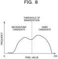
- FIGs. 8 and 9 are diagrams illustrating a case where the separation degree is small.
- FIG. 6 is a diagram illustrating a color histogram in a case where the first separation degree is large.
- the color histogram of the hand candidate in the color channel image and the color histogram of the background candidate in the color channel image are superimposed.
- the first separation degree can be defined as a size of an interval between a pixel value of a peak position of the color histogram of the background candidate and a pixel value of a peak position of the color histogram of the hand candidate.
- the first separation degree increases as the interval increases and decreases as the interval decreases.
- the first separation degree may be a low frequency at the bottom between the two peaks or the like.
- the first separation degree may be a value reflecting both of the above interval and the above low frequency.
- FIG. 7 is a diagram illustrating details in a case where the second separation degree is large.
- An upper diagram in FIG. 7 is a binarized image.
- a lower diagram in FIG. 7 is an image obtained by executing the morphology processing on the binarized image.
- the second separation degree is large, as illustrated in FIG. 7 , a region difference between before and after the morphology processing is reduced.
- FIG. 8 is a diagram illustrating a color histogram in a case where the first separation degree is small.
- the color histogram of the hand candidate in the color channel image and the color histogram of the background candidate in the color channel image are superimposed.
- the first separation degree is small, as illustrated in FIG. 8 , in the color histogram, separability between the background region and the palm region is lowered across the threshold of the binarization.
- FIG. 9 is a diagram illustrating details in a case where the second separation degree is small.
- An upper diagram in FIG. 9 is a binarized image.
- a lower diagram in FIG. 9 is an image obtained by executing the morphology processing on the binarized image.
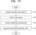
- FIG. 10 is a flowchart illustrating an example of registration processing executed by the detection device 100.
- the acquisition unit 11 acquires an original image captured by the camera 107 and an identification information (ID) of the registrant (step S21).
- ID is input by the registrant or the like using the input device 106, for example.
- the hand image detection unit 20 detects a hand image by the hand image detection processing described above (step S22).
- the biometric information extraction unit 21 extracts biometric information from the hand image detected in step S22 (step S23).
- the biometric information is a vein, a palm print, or the like.
- the biometric information is not particularly limited as long as the biometric information is obtained from the hand image.
- the storage unit 23 stores the biometric information extracted in step S23 as the registered biometric data, in association with the ID acquired in step S21 (step S24). Through the above processing, the registration processing is completed. For example, by repeating a plurality of times of this registration processing, it is possible to register the biometric information of the plurality of registrants.
- FIG. 11 is a flowchart illustrating an example of collation processing executed by the detection device 100.
- the acquisition unit 11 acquires an original image captured by the camera 107 (step S31).
- the hand image detection unit 20 detects a hand image by the hand image detection processing described above (step S32).
- the biometric information extraction unit 21 extracts the biometric information from the hand image detected in step S32, as biometric data for collation (step S33).
- the collation unit 22 performs authentication, by collating the biometric data for collation extracted in step S33 and each registered biometric data stored in the storage unit 23 (step S34). Specifically, it is determined whether or not a degree of similarity between each registered biometric data stored in the storage unit 23 and the biometric data for collation extracted in step S33 is equal to or more than a threshold. Then, if there is the registered biometric data of which the degree of similarity is equal to or more than the threshold, it is determined that the biometric data for collation is biometric information of a person having the ID of the registered biometric data. The collation unit 22 outputs a determination result.
- the separation degree is calculated that is an index used to determine the separability between the background image and the hand image, from each of the first color channel image and the second color channel image for the original image including the background image and the hand image.
- the color channel is selected based on the calculated separation degree.
- the hand image included in the original image is detected, using the selected color channel. In order to detect the hand image using the color channel with a high separation degree, the hand image and the background image can be accurately separated regardless of an imaging condition. Therefore, the detection accuracy of the hand image is improved.
- the separation degree is not particularly limited as long as the separation degree is the index used to determine the separability between the background image and the hand image.
- the detection accuracy of the separability between the background candidate and the hand candidate is enhanced.
- the second separation degree according to the region difference between before and after the morphology processing executed on at least one of the background candidate and the hand candidate is enhanced.
- the separability between the background candidate and the hand candidate for each of the plurality of small regions obtained from the original image it is possible to select the color channel for each small region.
- the detection accuracy of the hand image from the original image is further improved.
- By obtaining the small region using the key point regarding the part of the hand it is possible to reduce an influence of an individual difference of the palm. Therefore, the influence of the individual difference such as a size or a shape difference of the palm can be reduced.
- a processing amount for detecting the hand image can be reduced, by not selecting the color channel for the small region determined to be positioned in the hand.
- the color channel selection unit 19 is an example of a color channel selection unit that selects the color channel based on the separation degree that is the index calculated from each of the first color channel image and the second color channel image for the original image including the background image and the hand image and is used to determine the separability between the background image and the hand image.
- the hand image detection unit 20 is an example of a hand image detection unit that detects the hand image included in the original image, by using the color channel selected by the color channel selection unit.
- the binarization processing unit 16 is an example of a binarization processing unit that binarizes each of the first color channel image and the second color channel image.
- the candidate extraction unit 17 is an example of a candidate extraction unit that extracts the background candidate and the hand candidate from each of the first color channel image and the second color channel image that have been binarized.
- the separation degree calculation unit 18 is an example of a frequency distribution calculation unit that calculates the frequency distribution of the pixel value, for each of the background candidate and the hand candidate. Furthermore, the separation degree calculation unit 18 is an example of a morphology processing unit that executes morphology processing on at least one of the background candidate and the hand candidate.
- the region division unit 13 is an example of a region division unit that divides each of the first color channel image and the second color channel image into the plurality of regions.
- the determination unit 14 is an example of a determination unit that determines whether or not the plurality of regions includes the background, using the key point.
Landscapes
- Engineering & Computer Science (AREA)
- Theoretical Computer Science (AREA)
- General Physics & Mathematics (AREA)
- Physics & Mathematics (AREA)
- Multimedia (AREA)
- Computer Vision & Pattern Recognition (AREA)
- Artificial Intelligence (AREA)
- Health & Medical Sciences (AREA)
- Human Computer Interaction (AREA)
- Computing Systems (AREA)
- Databases & Information Systems (AREA)
- Evolutionary Computation (AREA)
- General Health & Medical Sciences (AREA)
- Medical Informatics (AREA)
- Software Systems (AREA)
- Image Analysis (AREA)
Abstract
Description
- This case relates to a detection device, a detection method, and a detection program.
- For palm vein authentication, palm print authentication, or the like, it has been required to accurately detect a hand image from an original image (for example, refer to Patent Document 1). Furthermore, a technique has been known for detecting a hand image from an image binarized by using brightness for an original image captured by performing irradiation with visible light (for example, refer to Patent Document 2).
- However, it is difficult to accurately detect a palm region.
- In one aspect, an object of the present invention is to provide a detection device, a detection method, and a detection program that can improve detection accuracy of a hand image.
- In one aspect, a detection device includes a color channel selection unit that selects a color channel, based on a separation degree that is an index calculated from each of a first color channel image and a second color channel image for an original image that includes a background image and a hand image and used to determine separability between the background image and the hand image and a hand image detection unit that detects the hand image included in the original image, using the color channel selected by the color channel selection unit.
- It is possible to improve detection accuracy of a hand image.
-
-
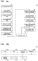
FIG. 1A is a block diagram illustrating an overall configuration of a detection device, andFIG. 1B is a block diagram illustrating a hardware configuration of the detection device. -
FIG. 2 is a flowchart illustrating an example of hand image detection processing executed by the detection device. -
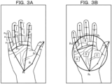
FIG. 3A is a diagram illustrating a key point, andFIG. 3B is a diagram illustrating a small region. -
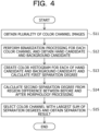
FIG. 4 is a diagram illustrating a flowchart illustrating details of step S6 inFIG. 2 . -
FIG. 5 is a diagram illustrating details of step S5 to step S7 inFIG. 2 . -
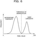
FIG. 6 is a diagram illustrating a case where a separation degree is large. -
FIG. 7 is a diagram illustrating a case where the separation degree is large. -
FIG. 8 is a diagram illustrating a case where the separation degree is small. -
FIG. 9 is a diagram illustrating a case where the separation degree is small. -
FIG. 10 is a flowchart illustrating an example of registration processing. -
FIG. 11 is a flowchart illustrating an example of collation processing. - Biometric authentication is a technology for performing identity verification using biometric information such as fingerprints, faces, or veins. In the biometric authentication, biometric data for collation obtained by a sensor is compared (collated) with registered biometric data registered in advance in a situation where confirmation is needed, and it is determined whether or not a degree of similarity is equal to or higher than an identity determination threshold, thereby verifying the identity.
- In palm vein authentication, palm print authentication, or the like, it is important to accurately detect a hand image from an original image. However, for example, in a case where imaging is performed using a typical camera such as a camera built in a mobile terminal, there is a possibility that it is difficult to separate the hand image from a background image depending on optical characteristics of the camera, an influence of reflection or shadow due to an influence of a light source, a color, a pattern, or the like of background.
- Therefore, in the following embodiments, a detection device, a detection method, and a detection program that can improve detection accuracy of a hand image by separating the hand image and the background image regardless of an imaging condition will be described.
-
FIG. 1A is a block diagram illustrating an overall configuration of adetection device 100. As illustrated inFIG. 1A , thedetection device 100 functions as anacquisition unit 11, a keypoint detection unit 12, aregion division unit 13, adetermination unit 14, a colorchannel conversion unit 15, abinarization processing unit 16, acandidate extraction unit 17, a separationdegree calculation unit 18, a colorchannel selection unit 19, a handimage detection unit 20, a biometricinformation extraction unit 21, acollation unit 22, astorage unit 23, and the like. -
FIG. 1B is a block diagram illustrating a hardware configuration of thedetection device 100. As illustrated inFIG. 1B , thedetection device 100 includes aCPU 101, a RAM 102, astorage device 103, an interface 104, adisplay device 105, an input device 106, acamera 107, and the like. - The Central Processing Unit (CPU) 101 is a central processing unit. The
CPU 101 includes one or more cores. The Random Access Memory (RAM) 102 is a volatile memory that temporarily stores a program to be executed by theCPU 101, data to be processed by theCPU 101, and the like. Thestorage device 103 is a non-volatile storage device. As thestorage device 103, for example, a Read Only Memory (ROM), a Solid State Drive (SSD: Solid State Drive) such as a flash memory, a hard disk to be driven by a hard disk drive, or the like may be used. Thestorage device 103 stores a detection program. The interface 104 is an interface device with an external device. For example, the interface 104 is an interface device with a Local Area Network (LAN). - The
display device 105 is a display device or the like such as a Liquid Crystal Device (LCD). The input device 106 is an input device such as a keyboard or a mouse. Thecamera 107 is a Metal Oxide Semiconductor (MOS) sensor, a Charged Coupled Device (CCD) sensor, or the like. - The
CPU 101 executes the detection program so as to implement theacquisition unit 11, the keypoint detection unit 12, theregion division unit 13, thedetermination unit 14, the colorchannel conversion unit 15, thebinarization processing unit 16, thecandidate extraction unit 17, the separationdegree calculation unit 18, the colorchannel selection unit 19, the handimage detection unit 20, the biometricinformation extraction unit 21, thecollation unit 22, and thestorage unit 23. Note that, as theacquisition unit 11, the keypoint detection unit 12, theregion division unit 13, thedetermination unit 14, the colorchannel conversion unit 15, thebinarization processing unit 16, thecandidate extraction unit 17, the separationdegree calculation unit 18, the colorchannel selection unit 19, the handimage detection unit 20, the biometricinformation extraction unit 21, thecollation unit 22, and thestorage unit 23, hardware such as a dedicated circuit may be used. -
FIG. 2 is a flowchart illustrating an example of hand image detection processing executed by thedetection device 100. An example of an operation of thedetection device 100 will be described with reference toFIG. 2 . - The
acquisition unit 11 acquires an original image including a hand image and a background image, from the camera 107 (step S1). - Next, the key
point detection unit 12 detects a plurality of key points indicating parts of a hand, in the original image acquired by the acquisition unit 11 (step S2). For example, the keypoint detection unit 12 detects 21 key points P0 to P20. The key point P0 is a point at a boundary between a palm and a wrist. The key point P1 is a point at a base of a thumb. The key point P2 is a point at a second joint of the thumb. The key point P3 is a point at a first joint of the thumb. The key point P4 is a point at a fingertip of the thumb. The key point P5 is a point at a base of an index finger. The key point P6 is a point at a second joint of the index finger. The key point P7 is a point at a first joint of the index finger. The key point P8 is a point at a fingertip of the index finger. The key point P9 is a point at a base of a middle finger. The key point P10 is a point at a second joint of the middle finger. The key point P11 is a point at a first joint of the middle finger. The key point P12 is a point at a fingertip of the middle finger. The key point P13 is a point at a base of a ring finger. The key point P14 is a point at a second joint of the ring finger. The key point P15 is a point at a first joint of the ring finger. The key point P16 is a point at a fingertip of the ring finger. The key point P17 is a point at a base of a little finger. The key point P18 is a point at a second joint of the little finger. The key point P19 is a point at a first joint of the little finger. The key point P20 is a point at a fingertip of the little finger. - These key points P0 to P20 can be detected, for example, from an RGB image. For example, the key points P0 to P20 can be obtained by detecting a Bounding box indicating a region of a hand and then detecting each portion of the hand. For example, the key points P0 to P20 can be detected by using a method in Non-Patent Document 1 "T. Simon, H. Joo, I. Matthews, and Y. Sheikh, "Hand keypoint detection in single images using multiview bootstrapping," in CVPR, 2017.". The key points P0 to P20 are illustrated in
FIG. 3A . - Next, the
region division unit 13 obtains a plurality of small regions A to D from the original image, using the key points (step S3). The small region is a region smaller than the original image.FIG. 3B is a diagram illustrating the small regions A to D. A black circle drawn by a black line is a circle passing through the key points P0, P6, and P18. The region D is a triangle having the key points P0, P5, and P17 as vertices. The small region B is a region obtained with the black circle, a straight line connecting the key points P6 and P5, a straight line connecting the key points P5 and P13, and a straight line connecting the key points P13 and P14. The small region A is a region on a left side of the small regions B and D, in the black circle. The small region C is a region on a right side of the small regions B and D, in the black circle. - Next, the
determination unit 14 determines whether or not each small region is contained in the hand, in a case of planar view (step S4). Since the entire region of the small region D is contained in the hand, it is determined as "Yes". Since the small regions A to C include background, it is determined as "No". - In a case where it is determined in step S4 as "Yes", the
determination unit 14 determines that the small region determined as "Yes" in step S4 is the region of the hand (step S5). - In a case where it is determined in step S4 as "No", the color
channel conversion unit 15, thebinarization processing unit 16, thecandidate extraction unit 17, the separationdegree calculation unit 18, and the colorchannel selection unit 19 separate the small region determined as "No" in step S4 into the region of the hand and the background region (step S6). Details will be described later. - Next, the hand
image detection unit 20 synthesizes the hand regions in the respective small regions obtained in steps S5 and S6, the handimage detection unit 20 detects the hand image (step S7). -
FIG. 4 is a diagram illustrating a flowchart illustrating details in step S6. Processing inFIG. 4 is executed on each small region determined as "No" in step S4. In the present embodiment, the processing inFIG. 4 is executed on each of the small regions A to C. - First, the color
channel conversion unit 15 converts the small region to be a target into a plurality of color channel images (step S11). The plurality of color channel images includes a first color channel image and a second color channel image that are at least two types of color channels. The color channel includes, for example, red (R), green (G), blue (B), hue (H: Hue), saturation (S: Saturation), brightness (V: value and brightness), a brightness (Y), a color difference (U), a color difference (V), or the like. For example, the colorchannel conversion unit 15 obtains an image of each color channel (hereinafter, referred to as color channel image), for the small region to be the target. Note that the plurality of color channel images may include a color channel image that includes three or more color channels. - Next, the
binarization processing unit 16 executes binarization processing using a predetermined threshold, on each color channel image and obtains a hand candidate and a background candidate (step S12). For example, the hand candidate is represented in white, and the background candidate is represented in black. - Next, the separation
degree calculation unit 18 creates each of a color histogram (frequency distribution of pixel value) of the hand candidate and a color histogram of the background candidate, for each color channel image before the binarization processing and calculates a first separation degree (step S13). For example, the binarization processing is executed on an R image, and the hand candidate and the background candidate are obtained. Next, each of a color histogram of the hand candidate and a color histogram of the background candidate is created, for the R image before the binarization processing. From superposition of these histograms, a first separation degree of the R image is calculated. - Next, the separation
degree calculation unit 18 executes morphology processing on at least one of the hand candidate and the background candidate, for each color channel image after the binarization processing. The morphology processing is filling a region. The separationdegree calculation unit 18 calculates a second separation degree from a region difference between before and after the morphology processing (step S14). - Next, the color
channel selection unit 19 selects a color channel that maximizes a sum of the first separation degree and the second separation degree and obtains a result of separation from the palm to the background (step S15). For example, by normalizing the first separation degree and the second separation degree, it is possible to quantify the first separation degree and the second separation degree on the same scale. For example, by expressing the first separation degree and the second separation degree as numerical values from zero to 100, the sum of the first separation degree and the second separation degree can be compared at the same standard for each color channel. -
FIG. 5 is a diagram illustrating details of steps S5 to S7 inFIG. 2 . As illustrated inFIG. 5 , for each of the small regions A to C, a plurality of color channel images is obtained. For each of the small regions A to C, a color channel image that maximizes the sum of the first separation degree and the second separation degree is selected. In the example inFIG. 5 , an R image is selected in the small region A, a G image is selected in the small region B, and an R image is selected in the small region C. Thereafter, a palm region is synthesized from an image after the binarization processing of the selected color channel image. For the small region D, the color channel is not selected, and the binarization processing is executed. The synthesized palm region is shaped by the morphology processing. By extracting a region corresponding to the region shaped by the morphology processing from the original image, it is possible to improve detection accuracy of the hand image. Note that, for example, the hand image is an image indicating the palm region. -
FIGs. 6 to 9 are diagrams illustrating details of the calculation of the first separation degree and the second separation degree.FIGs. 6 and7 are diagrams illustrating a case where the separation degree is large.FIGs. 8 and9 are diagrams illustrating a case where the separation degree is small. -
FIG. 6 is a diagram illustrating a color histogram in a case where the first separation degree is large. InFIG. 6 , the color histogram of the hand candidate in the color channel image and the color histogram of the background candidate in the color channel image are superimposed. When the first separation degree is large, as illustrated inFIG. 6 , separability between the background candidate and the hand region is enhanced across a threshold of binarization. For example, the first separation degree can be defined as a size of an interval between a pixel value of a peak position of the color histogram of the background candidate and a pixel value of a peak position of the color histogram of the hand candidate. The first separation degree increases as the interval increases and decreases as the interval decreases. Alternatively, the first separation degree may be a low frequency at the bottom between the two peaks or the like. Alternatively, the first separation degree may be a value reflecting both of the above interval and the above low frequency. -
FIG. 7 is a diagram illustrating details in a case where the second separation degree is large. An upper diagram inFIG. 7 is a binarized image. A lower diagram inFIG. 7 is an image obtained by executing the morphology processing on the binarized image. When the second separation degree is large, as illustrated inFIG. 7 , a region difference between before and after the morphology processing is reduced. -
FIG. 8 is a diagram illustrating a color histogram in a case where the first separation degree is small. InFIG. 8 , the color histogram of the hand candidate in the color channel image and the color histogram of the background candidate in the color channel image are superimposed. When the first separation degree is small, as illustrated inFIG. 8 , in the color histogram, separability between the background region and the palm region is lowered across the threshold of the binarization. -
FIG. 9 is a diagram illustrating details in a case where the second separation degree is small. An upper diagram inFIG. 9 is a binarized image. A lower diagram inFIG. 9 is an image obtained by executing the morphology processing on the binarized image. When the second separation degree is small, as illustrated inFIG. 9 , the region difference between before and after the morphology processing increases. - Hereinafter, biometric authentication processing using the detected palm region will be described.
-
FIG. 10 is a flowchart illustrating an example of registration processing executed by thedetection device 100. - As illustrated in
FIG. 10 , theacquisition unit 11 acquires an original image captured by thecamera 107 and an identification information (ID) of the registrant (step S21). The ID is input by the registrant or the like using the input device 106, for example. - Next, the hand
image detection unit 20 detects a hand image by the hand image detection processing described above (step S22). - Next, the biometric
information extraction unit 21 extracts biometric information from the hand image detected in step S22 (step S23). The biometric information is a vein, a palm print, or the like. However, the biometric information is not particularly limited as long as the biometric information is obtained from the hand image. - The
storage unit 23 stores the biometric information extracted in step S23 as the registered biometric data, in association with the ID acquired in step S21 (step S24). Through the above processing, the registration processing is completed. For example, by repeating a plurality of times of this registration processing, it is possible to register the biometric information of the plurality of registrants. -
FIG. 11 is a flowchart illustrating an example of collation processing executed by thedetection device 100. - As illustrated in
FIG. 11 , theacquisition unit 11 acquires an original image captured by the camera 107 (step S31). - Next, the hand
image detection unit 20 detects a hand image by the hand image detection processing described above (step S32). - Next, the biometric
information extraction unit 21 extracts the biometric information from the hand image detected in step S32, as biometric data for collation (step S33). - The
collation unit 22 performs authentication, by collating the biometric data for collation extracted in step S33 and each registered biometric data stored in the storage unit 23 (step S34). Specifically, it is determined whether or not a degree of similarity between each registered biometric data stored in thestorage unit 23 and the biometric data for collation extracted in step S33 is equal to or more than a threshold. Then, if there is the registered biometric data of which the degree of similarity is equal to or more than the threshold, it is determined that the biometric data for collation is biometric information of a person having the ID of the registered biometric data. Thecollation unit 22 outputs a determination result. - According to the present embodiment, the separation degree is calculated that is an index used to determine the separability between the background image and the hand image, from each of the first color channel image and the second color channel image for the original image including the background image and the hand image. The color channel is selected based on the calculated separation degree. The hand image included in the original image is detected, using the selected color channel. In order to detect the hand image using the color channel with a high separation degree, the hand image and the background image can be accurately separated regardless of an imaging condition. Therefore, the detection accuracy of the hand image is improved.
- Note that the separation degree is not particularly limited as long as the separation degree is the index used to determine the separability between the background image and the hand image.
- However, by using the first separation degree calculated from the color histogram calculated for each of the background candidate and the hand candidate, the detection accuracy of the separability between the background candidate and the hand candidate is enhanced. Furthermore, by using the second separation degree according to the region difference between before and after the morphology processing executed on at least one of the background candidate and the hand candidate, the detection accuracy of the separability between the background candidate and the hand candidate is enhanced.
- Furthermore, by determining the separability between the background candidate and the hand candidate for each of the plurality of small regions obtained from the original image, it is possible to select the color channel for each small region. As a result, the detection accuracy of the hand image from the original image is further improved. By obtaining the small region using the key point regarding the part of the hand, it is possible to reduce an influence of an individual difference of the palm. Therefore, the influence of the individual difference such as a size or a shape difference of the palm can be reduced. A processing amount for detecting the hand image can be reduced, by not selecting the color channel for the small region determined to be positioned in the hand.
- Note that, in each example described above, the color
channel selection unit 19 is an example of a color channel selection unit that selects the color channel based on the separation degree that is the index calculated from each of the first color channel image and the second color channel image for the original image including the background image and the hand image and is used to determine the separability between the background image and the hand image. The handimage detection unit 20 is an example of a hand image detection unit that detects the hand image included in the original image, by using the color channel selected by the color channel selection unit. Thebinarization processing unit 16 is an example of a binarization processing unit that binarizes each of the first color channel image and the second color channel image. Thecandidate extraction unit 17 is an example of a candidate extraction unit that extracts the background candidate and the hand candidate from each of the first color channel image and the second color channel image that have been binarized. The separationdegree calculation unit 18 is an example of a frequency distribution calculation unit that calculates the frequency distribution of the pixel value, for each of the background candidate and the hand candidate. Furthermore, the separationdegree calculation unit 18 is an example of a morphology processing unit that executes morphology processing on at least one of the background candidate and the hand candidate. Theregion division unit 13 is an example of a region division unit that divides each of the first color channel image and the second color channel image into the plurality of regions. Thedetermination unit 14 is an example of a determination unit that determines whether or not the plurality of regions includes the background, using the key point. - While the embodiments of the present invention have been described above in detail, the present invention is not limited to such specific embodiments, and various modifications and alterations may be made within the scope of the present invention described in the claims.
-
- Patent Document 1:
Japanese Laid-open Patent Publication No. 2018-026012 - Patent Document 2:
Japanese Patent No. 6629150 - Non-Patent Document 1: T. Simon, H. Joo, I. Matthews, and Y. Sheikh, "Hand keypoint detection in single images using multiview bootstrapping," in CVPR, 2017.
-
- 11
- acquisition unit
- 12
- key point detection unit
- 13
- region division unit
- 14
- determination unit
- 15
- color channel conversion unit
- 16
- binarization processing unit
- 17
- candidate extraction unit
- 18
- separation degree calculation unit
- 19
- color channel selection unit
- 20
- hand image detection unit
- 21
- biometric information extraction unit
- 22
- collation unit
- 23
- storage unit
- 100
- detection device
- 105
- display device
- 107
- camera
Claims (21)
- A detection device comprising:a color channel selection unit configured to select a color channel, based on a separation degree that is an index calculated from each of a first color channel image and a second color channel image for an original image that includes a background image and a hand image and used to determine separability between the background image and the hand image; anda hand image detection unit configured to detect the hand image included in the original image, by using the color channel selected by the color channel selection unit.
- The detection device according to claim 1, further comprising:a binarization processing unit configured to binarize each of the first color channel image and the second color channel image;a candidate extraction unit configured to extract a background candidate and a hand candidate, from each of the first color channel image and the second color channel image that have been binarized; anda frequency distribution calculation unit configured to calculate a frequency distribution of a pixel value, for each of the background candidate and the hand candidate, whereinthe separation degree includes a first separation degree calculated from the frequency distribution of the pixel value.
- The detection device according to claim 2, wherein the first separation degree is a separation degree according to a pixel value difference between two frequency peaks, in the frequency distribution of the pixel value.
- The detection device according to claim 1, further comprising:a binarization processing unit configured to binarize each of the first color channel image and the second color channel image;a candidate extraction unit configured to extract a background candidate and a hand candidate, from each of the first color channel image and second color channel image that have been binarized; anda morphology processing unit configured to execute morphology processing on at least one of the background candidate and the hand candidate, whereinthe separation degree includes a second separation degree according to a region difference between before and after the morphology processing.
- The detection device according to any one of claims 1 to 4, further comprising:a region division unit configured to divide each of the first color channel image and the second color channel image into a plurality of regions, whereinthe color channel selection unit selects the color channel according to the separation degree of each of the plurality of regions.
- The detection device according to claim 5, wherein the region division unit divides each of the first color channel image and the second color channel image into the plurality of regions, according to a key point for a part of a hand detected from the original image.
- The detection device according to claim 6, further comprising:a determination unit configured to determine whether or not the plurality of regions includes background, by using the key point, whereinthe color channel selection unit is configured not to performs the selecting of the color channel on a region determined not to include the background by the determination unit, andthe hand image detection unit is configured to detect, as the hand image, the region determined not to include the background.
- A detection method implemented by a computer, the detection method comprising:the computer selecting a color channel, based on a separation degree that is an index calculated from each of a first color channel image and a second color channel image for an original image that includes a background image and a hand image and used to determine separability between the background image and the hand image; andthe computer detecting the hand image included in the original image, by using the color channel selected.
- The detection method according to claim 8, further comprising:the computer binarizing each of the first color channel image and the second color channel image;the computer extracting a background candidate and a hand candidate, from each of the first color channel image and the second color channel image that have been binarized; andthe computer calculating a frequency distribution of a pixel value, for each of the background candidate and the hand candidate, whereinthe separation degree includes a first separation degree calculated from the frequency distribution of the pixel value.
- The detection method according to claim 9, wherein the first separation degree is a separation degree according to a pixel value difference between two frequency peaks, in the frequency distribution of the pixel value.
- The detection method according to claim 8, further comprising:the computer binarizing each of the first color channel image and the second color channel image;the computer extracting a background candidate and a hand candidate, from each of the first color channel image and second color channel image that have been binarized; andthe computer executing morphology processing on at least one of the background candidate and the hand candidate, whereinthe separation degree includes a second separation degree according to a region difference between before and after the morphology processing.
- The detection method according to any one of claims 8 to 11, further comprising:the computer dividing each of the first color channel image and the second color channel image into a plurality of regions, whereinthe selecting of the color channel is performed for each region of the plurality of regions to select the color channel according to the separation degree of the each region.
- The detection method according to claim 12, wherein the dividing includes dividing each of the first color channel image and the second color channel image into the plurality of regions, according to a key point for a part of a hand detected from the original image.
- The detection method according to claim 13, further comprising:the computer determining whether or not the plurality of regions includes background, by using the key point, whereinthe selecting of the color channel is not performed on a region determined not to include the background, andthe region determined not to include the background is detected as the hand image.
- A detection program comprising instructions which, when executed by a computer, cause the computer to perform processing comprising:the computer selecting a color channel, based on a separation degree that is an index calculated from each of a first color channel image and a second color channel image for an original image that includes a background image and a hand image and used to determine separability between the background image and the hand image; andthe computer detecting the hand image included in the original image, by using the color channel selected.
- The detection program according to claim 15, the processing further comprising:the computer binarizing each of the first color channel image and the second color channel image;the computer extracting a background candidate and a hand candidate, from each of the first color channel image and the second color channel image that have been binarized; andthe computer calculating a frequency distribution of a pixel value, for each of the background candidate and the hand candidate, whereinthe separation degree includes a first separation degree calculated from the frequency distribution of the pixel value.
- The detection program according to claim 16, wherein the first separation degree is a separation degree according to a pixel value difference between two frequency peaks, in the frequency distribution of the pixel value.
- The detection program according to claim 15, the processing further comprising:the computer binarizing each of the first color channel image and the second color channel image;the computer extracting a background candidate and a hand candidate, from each of the first color channel image and second color channel image that have been binarized; andthe computer executing morphology processing on at least one of the background candidate and the hand candidate, whereinthe separation degree includes a second separation degree according to a region difference between before and after the morphology processing.
- The detection program according to any one of claims 15 to 18, the processing further comprising:the computer dividing each of the first color channel image and the second color channel image into a plurality of regions, whereinthe selecting of the color channel is performed for each region of the plurality of regions to select the color channel according to the separation degree of the each region.
- The detection program according to claim 19, wherein the dividing includes dividing each of the first color channel image and the second color channel image into the plurality of regions, according to a key point for a part of a hand detected from the original image.
- The detection program according to claim 20, the processing further comprising:the computer determining whether or not the plurality of regions includes background, by using the key point, whereinthe selecting of the color channel is not performed on a region determined not to include the background, andthe region determined not to include the background is detected as the hand image.
Applications Claiming Priority (1)
| Application Number | Priority Date | Filing Date | Title |
|---|---|---|---|
| PCT/JP2022/032990 WO2024047847A1 (en) | 2022-09-01 | 2022-09-01 | Detection device, detection method, and detection program |
Publications (2)
| Publication Number | Publication Date |
|---|---|
| EP4583053A1 true EP4583053A1 (en) | 2025-07-09 |
| EP4583053A4 EP4583053A4 (en) | 2025-08-13 |
Family
ID=90099054
Family Applications (1)
| Application Number | Title | Priority Date | Filing Date |
|---|---|---|---|
| EP22957442.1A Withdrawn EP4583053A4 (en) | 2022-09-01 | 2022-09-01 | DETECTION DEVICE, DETECTION METHOD AND DETECTION PROGRAM |
Country Status (5)
| Country | Link |
|---|---|
| US (1) | US20250173994A1 (en) |
| EP (1) | EP4583053A4 (en) |
| JP (1) | JP7759007B2 (en) |
| CN (1) | CN119678186A (en) |
| WO (1) | WO2024047847A1 (en) |
Family Cites Families (8)
| Publication number | Priority date | Publication date | Assignee | Title |
|---|---|---|---|---|
| CA2077324C (en) * | 1991-10-07 | 1997-06-24 | Michael R. Campanelli | Image editing system and method having improved automatic object selection |
| JP5196337B1 (en) * | 2011-04-28 | 2013-05-15 | 株式会社湯山製作所 | Drug inspection device and drug packaging device |
| JP5796523B2 (en) | 2012-03-27 | 2015-10-21 | 富士通株式会社 | Biological information acquisition apparatus, biological information acquisition method, and biological information acquisition control program |
| JP6617570B2 (en) | 2016-01-13 | 2019-12-11 | 富士通株式会社 | Biometric authentication device, biometric authentication method, and biometric authentication program |
| JP6658188B2 (en) | 2016-03-24 | 2020-03-04 | 富士通株式会社 | Image processing apparatus, image processing method, and image processing program |
| JP6629150B2 (en) | 2016-08-10 | 2020-01-15 | Kddi株式会社 | Palm detection device, palm print authentication device, palm detection method, and program |
| JP6754642B2 (en) * | 2016-09-01 | 2020-09-16 | 株式会社日立製作所 | Biodetector |
| JP6790611B2 (en) * | 2016-09-02 | 2020-11-25 | 富士通株式会社 | Bioimage processing device, bioimage processing method, and bioimage processing program |
-
2022
- 2022-09-01 EP EP22957442.1A patent/EP4583053A4/en not_active Withdrawn
- 2022-09-01 JP JP2024543733A patent/JP7759007B2/en active Active
- 2022-09-01 CN CN202280098913.4A patent/CN119678186A/en active Pending
- 2022-09-01 WO PCT/JP2022/032990 patent/WO2024047847A1/en not_active Ceased
-
2025
- 2025-01-28 US US19/039,541 patent/US20250173994A1/en active Pending
Also Published As
| Publication number | Publication date |
|---|---|
| CN119678186A (en) | 2025-03-21 |
| JPWO2024047847A1 (en) | 2024-03-07 |
| JP7759007B2 (en) | 2025-10-23 |
| WO2024047847A1 (en) | 2024-03-07 |
| EP4583053A4 (en) | 2025-08-13 |
| US20250173994A1 (en) | 2025-05-29 |
Similar Documents
| Publication | Publication Date | Title |
|---|---|---|
| KR100480781B1 (en) | Method of extracting teeth area from teeth image and personal identification method and apparatus using teeth image | |
| CN110059702B (en) | Method and device for object contour recognition | |
| EP2833288B1 (en) | Face calibration method and system, and computer storage medium | |
| US8175380B2 (en) | Apparatus and method for improving text recognition capability | |
| US9208375B2 (en) | Face recognition mechanism | |
| US8744189B2 (en) | Character region extracting apparatus and method using character stroke width calculation | |
| KR100651753B1 (en) | Eye detection method and apparatus using symmetry and moment characteristics of objects | |
| TW201437925A (en) | Object identification device, method, and storage medium | |
| US6327385B1 (en) | Character segmentation device and character segmentation system | |
| EP2908267A1 (en) | Image processing device and image processing method | |
| JP6115388B2 (en) | License plate recognition device and license plate recognition method | |
| KR20210081267A (en) | Apparatus for processing image, storage medium, and image processing method | |
| JP2009123206A (en) | Method and apparatus for extracting text from an image | |
| CN113722692B (en) | Identity recognition device and method thereof | |
| WO2021192315A1 (en) | Stripe pattern image collating device, stripe pattern collating method, and computer-readable medium storing program thereof | |
| JP2008251029A (en) | Character recognition device and license plate recognition system | |
| EP2541469A2 (en) | Image recognition device, image recognition method and image recognition program | |
| JP5857634B2 (en) | Word space detection device, word space detection method, and computer program for word space detection | |
| JP2014120066A (en) | Image processor, image processing method and image processing program | |
| CN110334598B (en) | Palmprint recognition method and device | |
| US20250173994A1 (en) | Detection device, detection method, and non-transitory computer-readable recording medium storing detection program | |
| KR20190119470A (en) | Serial number recognition Apparatus and method for paper money | |
| JP3319408B2 (en) | Facial feature extraction device | |
| KR101329492B1 (en) | Apparatus and method for controlling camera for locating scene text to proper position and size | |
| JP6790611B2 (en) | Bioimage processing device, bioimage processing method, and bioimage processing program |
Legal Events
| Date | Code | Title | Description |
|---|---|---|---|
| STAA | Information on the status of an ep patent application or granted ep patent |
Free format text: STATUS: THE INTERNATIONAL PUBLICATION HAS BEEN MADE |
|
| PUAI | Public reference made under article 153(3) epc to a published international application that has entered the european phase |
Free format text: ORIGINAL CODE: 0009012 |
|
| STAA | Information on the status of an ep patent application or granted ep patent |
Free format text: STATUS: REQUEST FOR EXAMINATION WAS MADE |
|
| 17P | Request for examination filed |
Effective date: 20250128 |
|
| AK | Designated contracting states |
Kind code of ref document: A1 Designated state(s): AL AT BE BG CH CY CZ DE DK EE ES FI FR GB GR HR HU IE IS IT LI LT LU LV MC MK MT NL NO PL PT RO RS SE SI SK SM TR |
|
| A4 | Supplementary search report drawn up and despatched |
Effective date: 20250711 |
|
| RIC1 | Information provided on ipc code assigned before grant |
Ipc: G06T 7/90 20170101AFI20250707BHEP Ipc: G06V 10/26 20220101ALI20250707BHEP Ipc: G06V 10/56 20220101ALI20250707BHEP |
|
| STAA | Information on the status of an ep patent application or granted ep patent |
Free format text: STATUS: THE APPLICATION HAS BEEN WITHDRAWN |
|
| 18W | Application withdrawn |
Effective date: 20251023 |