EP4582910A2 - Hall joystick - Google Patents
Hall joystick Download PDFInfo
- Publication number
- EP4582910A2 EP4582910A2 EP25171722.9A EP25171722A EP4582910A2 EP 4582910 A2 EP4582910 A2 EP 4582910A2 EP 25171722 A EP25171722 A EP 25171722A EP 4582910 A2 EP4582910 A2 EP 4582910A2
- Authority
- EP
- European Patent Office
- Prior art keywords
- side cap
- rotating member
- rotating
- magnet
- main body
- Prior art date
- Legal status (The legal status is an assumption and is not a legal conclusion. Google has not performed a legal analysis and makes no representation as to the accuracy of the status listed.)
- Pending
Links
Images




Classifications
-
- G—PHYSICS
- G05—CONTROLLING; REGULATING
- G05G—CONTROL DEVICES OR SYSTEMS INSOFAR AS CHARACTERISED BY MECHANICAL FEATURES ONLY
- G05G9/00—Manually-actuated control mechanisms provided with one single controlling member co-operating with two or more controlled members, e.g. selectively, simultaneously
- G05G9/02—Manually-actuated control mechanisms provided with one single controlling member co-operating with two or more controlled members, e.g. selectively, simultaneously the controlling member being movable in different independent ways, movement in each individual way actuating one controlled member only
- G05G9/04—Manually-actuated control mechanisms provided with one single controlling member co-operating with two or more controlled members, e.g. selectively, simultaneously the controlling member being movable in different independent ways, movement in each individual way actuating one controlled member only in which movement in two or more ways can occur simultaneously
- G05G9/047—Manually-actuated control mechanisms provided with one single controlling member co-operating with two or more controlled members, e.g. selectively, simultaneously the controlling member being movable in different independent ways, movement in each individual way actuating one controlled member only in which movement in two or more ways can occur simultaneously the controlling member being movable by hand about orthogonal axes, e.g. joysticks
-
- A—HUMAN NECESSITIES
- A63—SPORTS; GAMES; AMUSEMENTS
- A63F—CARD, BOARD, OR ROULETTE GAMES; INDOOR GAMES USING SMALL MOVING PLAYING BODIES; VIDEO GAMES; GAMES NOT OTHERWISE PROVIDED FOR
- A63F13/00—Video games, i.e. games using an electronically generated display having two or more dimensions
- A63F13/20—Input arrangements for video game devices
- A63F13/24—Constructional details thereof, e.g. game controllers with detachable joystick handles
-
- A—HUMAN NECESSITIES
- A63—SPORTS; GAMES; AMUSEMENTS
- A63F—CARD, BOARD, OR ROULETTE GAMES; INDOOR GAMES USING SMALL MOVING PLAYING BODIES; VIDEO GAMES; GAMES NOT OTHERWISE PROVIDED FOR
- A63F13/00—Video games, i.e. games using an electronically generated display having two or more dimensions
- A63F13/90—Constructional details or arrangements of video game devices not provided for in groups A63F13/20 or A63F13/25, e.g. housing, wiring, connections or cabinets
- A63F13/98—Accessories, i.e. detachable arrangements optional for the use of the video game device, e.g. grip supports of game controllers
-
- G—PHYSICS
- G06—COMPUTING OR CALCULATING; COUNTING
- G06F—ELECTRIC DIGITAL DATA PROCESSING
- G06F3/00—Input arrangements for transferring data to be processed into a form capable of being handled by the computer; Output arrangements for transferring data from processing unit to output unit, e.g. interface arrangements
- G06F3/01—Input arrangements or combined input and output arrangements for interaction between user and computer
- G06F3/03—Arrangements for converting the position or the displacement of a member into a coded form
- G06F3/033—Pointing devices displaced or positioned by the user, e.g. mice, trackballs, pens or joysticks; Accessories therefor
- G06F3/0338—Pointing devices displaced or positioned by the user, e.g. mice, trackballs, pens or joysticks; Accessories therefor with detection of limited linear or angular displacement of an operating part of the device from a neutral position, e.g. isotonic or isometric joysticks
-
- G—PHYSICS
- G05—CONTROLLING; REGULATING
- G05G—CONTROL DEVICES OR SYSTEMS INSOFAR AS CHARACTERISED BY MECHANICAL FEATURES ONLY
- G05G9/00—Manually-actuated control mechanisms provided with one single controlling member co-operating with two or more controlled members, e.g. selectively, simultaneously
- G05G9/02—Manually-actuated control mechanisms provided with one single controlling member co-operating with two or more controlled members, e.g. selectively, simultaneously the controlling member being movable in different independent ways, movement in each individual way actuating one controlled member only
- G05G9/04—Manually-actuated control mechanisms provided with one single controlling member co-operating with two or more controlled members, e.g. selectively, simultaneously the controlling member being movable in different independent ways, movement in each individual way actuating one controlled member only in which movement in two or more ways can occur simultaneously
- G05G9/047—Manually-actuated control mechanisms provided with one single controlling member co-operating with two or more controlled members, e.g. selectively, simultaneously the controlling member being movable in different independent ways, movement in each individual way actuating one controlled member only in which movement in two or more ways can occur simultaneously the controlling member being movable by hand about orthogonal axes, e.g. joysticks
- G05G2009/04703—Mounting of controlling member
- G05G2009/04714—Mounting of controlling member with orthogonal axes
- G05G2009/04718—Mounting of controlling member with orthogonal axes with cardan or gimbal type joint
-
- G—PHYSICS
- G05—CONTROLLING; REGULATING
- G05G—CONTROL DEVICES OR SYSTEMS INSOFAR AS CHARACTERISED BY MECHANICAL FEATURES ONLY
- G05G9/00—Manually-actuated control mechanisms provided with one single controlling member co-operating with two or more controlled members, e.g. selectively, simultaneously
- G05G9/02—Manually-actuated control mechanisms provided with one single controlling member co-operating with two or more controlled members, e.g. selectively, simultaneously the controlling member being movable in different independent ways, movement in each individual way actuating one controlled member only
- G05G9/04—Manually-actuated control mechanisms provided with one single controlling member co-operating with two or more controlled members, e.g. selectively, simultaneously the controlling member being movable in different independent ways, movement in each individual way actuating one controlled member only in which movement in two or more ways can occur simultaneously
- G05G9/047—Manually-actuated control mechanisms provided with one single controlling member co-operating with two or more controlled members, e.g. selectively, simultaneously the controlling member being movable in different independent ways, movement in each individual way actuating one controlled member only in which movement in two or more ways can occur simultaneously the controlling member being movable by hand about orthogonal axes, e.g. joysticks
- G05G2009/0474—Manually-actuated control mechanisms provided with one single controlling member co-operating with two or more controlled members, e.g. selectively, simultaneously the controlling member being movable in different independent ways, movement in each individual way actuating one controlled member only in which movement in two or more ways can occur simultaneously the controlling member being movable by hand about orthogonal axes, e.g. joysticks characterised by means converting mechanical movement into electric signals
- G05G2009/04755—Magnetic sensor, e.g. hall generator, pick-up coil
-
- G—PHYSICS
- G05—CONTROLLING; REGULATING
- G05G—CONTROL DEVICES OR SYSTEMS INSOFAR AS CHARACTERISED BY MECHANICAL FEATURES ONLY
- G05G9/00—Manually-actuated control mechanisms provided with one single controlling member co-operating with two or more controlled members, e.g. selectively, simultaneously
- G05G9/02—Manually-actuated control mechanisms provided with one single controlling member co-operating with two or more controlled members, e.g. selectively, simultaneously the controlling member being movable in different independent ways, movement in each individual way actuating one controlled member only
- G05G9/04—Manually-actuated control mechanisms provided with one single controlling member co-operating with two or more controlled members, e.g. selectively, simultaneously the controlling member being movable in different independent ways, movement in each individual way actuating one controlled member only in which movement in two or more ways can occur simultaneously
- G05G9/047—Manually-actuated control mechanisms provided with one single controlling member co-operating with two or more controlled members, e.g. selectively, simultaneously the controlling member being movable in different independent ways, movement in each individual way actuating one controlled member only in which movement in two or more ways can occur simultaneously the controlling member being movable by hand about orthogonal axes, e.g. joysticks
- G05G2009/04766—Manually-actuated control mechanisms provided with one single controlling member co-operating with two or more controlled members, e.g. selectively, simultaneously the controlling member being movable in different independent ways, movement in each individual way actuating one controlled member only in which movement in two or more ways can occur simultaneously the controlling member being movable by hand about orthogonal axes, e.g. joysticks providing feel, e.g. indexing means, means to create counterforce
Definitions
- the present disclosure generally relates to joysticks, and particularly to a Hall joystick.
- the joystick switch also known as joystick
- a gaming controller is an important part for a user to control electronic games.
- Some conventional joysticks may include a frame, a first rotating member, a second rotating member, a stick, a rod seat and a base.
- the first rotating member is rotatably mounted on the frame.
- the second rotating member extends in a direction orthogonal to the longitudinal direction of the first rotating member and is rotatably mounted on the frame.
- the stick can be tilted and the top of the stick extends out of the frame.
- the rod seat is movable and arranged in an axial direction of the stick.
- the base is arranged at the lower part of the frame.
- a spring is usually arranged between the stick and the rod seat, and the spring is to return the stick to its original position.
- Electronic components are mounted on a housing.
- an integrated joystick with Hall elements may include a return spring 52, a transmission member 3 (see FIG. 9 ), a first side cap 1, a second cap 2, a stick 4, and a main body 5.
- the main body 5 is hollow and includes a first side surface 501 and a second side surface 502 that are perpendicular to each other.
- the return spring 52 is arranged within the main body 5.
- the first side cap 1 and the second cap 2 are respectively fixed to the fist side surface 501 and the second side surface 502.
- the stick 4 is partly received in the main body 5 and has a lower end 401 rotatably connected to the main body 5.
- the first Hall element 11 is arranged within the first side cap 1, and the second Hall element 21 is arranged within the second side cap 2.
- the first Hall element 11 and the second Hall element 21 are integrally connected with the corresponding side caps. When assembled on the assembly line, rapid assembling can be achieved by insertion of the pins on the first Hall element 11 and the second Hall element 21 to a circuit board. It also realizes the non-contact position detection of the joystick, with long service life, high precision and no drift problem.
- the manner in which the first side cap 1 and the second side cap 2 are arranged enables two linear Hall magnetic induction sensors (i.e., the two Hall elements) to detect the position of the stick 4, which has the advantages of simple structure, low power consumption, simple detection operation, and lower cost.
- the internal structures of the first side cap 1 and the second side cap 2 are the same.
- an in-mold poly-molding process can be used to integrally arrange the first Hall element 11 inside the first side cap 1, and integrally arrange the second Hall element 21 inside the second side cap 2.
- the main body 5 includes therein a rotatable post 51.
- the spring 52 is arranged around the post 51.
- the stick 4 defines a hollow space 402, and the post 51 is received in the hollow space 402.
- An upper end of the return spring 52 abuts against the stick 4.
- the stick 4 is rotatable together with the rotatable post 51 about a lower end of the post 51 in contact with the main body 5.
- the transmission member 3 may include a first transmission member 31 and a second transmission member 32 that are rotatably connected to the main body 5 and rotatable about two different axes 301 and 302.
- the stick 4 is rotatably connected to the second transmission member 32, and is rotatable about an axis of rotation 403.
- the axis of rotation 403 coincides with the axis 301.
- the two axes 301 and 302 are perpendicular to each other.
- the first transmission member 31 may include a U-shaped body 311
- the second transmission member 32 may include a hollow body 321 that is formed by four sidewalls connected to one another.
- the stick 4 when the stick 4 rotates about the axis of rotation 403 that is perpendicular to the first side cap 1, the stick 4 will come into contact U-shaped body 311 and push the first transmission member 31 to rotate, thereby causing the first connection portion 312 to rotate.
- the first rotating member 12 then rotates together with the first connection portion 312, thereby causing the magnet 14 within the first rotating member 12 to rotate.
- the first Hall element 11 can detect the change in the magnetic field caused by the rotation of the magnet 14 inside the first rotating member 12.
- the second transmission member 32 rotates about the axis 302 that is perpendicular to the second side cap 2, thereby causing the second connection portion 322 to rotate.
- the second rotating member 22 then rotates together with the second connection portion 322, thereby causing the magnet 14 within the second rotating member 22 to rotate.
- the second Hall element 21 can detect the change in the magnetic field caused by the rotation of the magnet 14 inside the second rotating member 22.
- the first Hall element 11 is arranged under the magnet 14 within the first rotating member 12, and the second Hall element 21 is arranged under the magnet 14 within the first rotating member 22.
Landscapes
- Engineering & Computer Science (AREA)
- Multimedia (AREA)
- Physics & Mathematics (AREA)
- General Physics & Mathematics (AREA)
- Automation & Control Theory (AREA)
- General Engineering & Computer Science (AREA)
- Human Computer Interaction (AREA)
- Theoretical Computer Science (AREA)
- Mechanical Control Devices (AREA)
- Position Input By Displaying (AREA)
- Switches With Compound Operations (AREA)
Abstract
Description
- The present disclosure generally relates to joysticks, and particularly to a Hall joystick.
- With the improvement of living standards, people's leisure activities are becoming more and more various. Electronic gaming devices that incorporate various functions, such as leisure and entertainment, intellectual development, emotional intelligence development, and even exercise and fitness are more and more popular. As an important component of electronic gaming devices, the joystick switch (also known as joystick) of a gaming controller is an important part for a user to control electronic games.
- Some conventional joysticks may include a frame, a first rotating member, a second rotating member, a stick, a rod seat and a base. The first rotating member is rotatably mounted on the frame. The second rotating member extends in a direction orthogonal to the longitudinal direction of the first rotating member and is rotatably mounted on the frame. The stick can be tilted and the top of the stick extends out of the frame. The rod seat is movable and arranged in an axial direction of the stick. The base is arranged at the lower part of the frame. A spring is usually arranged between the stick and the rod seat, and the spring is to return the stick to its original position. Electronic components are mounted on a housing.
- These conventional joysticks have the following drawbacks: the electronic components are mounted on the housing and are located outside the frame, which makes the electrical components protrude from the whole, resulting in a large product size and hindering the integrated development of products. In addition, there are many parts and the structure is complicated, resulting in low production efficiency.
- Some analog control joysticks on the market generally adopt the resistive film structure, which is simple in structure and low in cost. However, because of the sliding rheostat structure that the metal or carbon brush slides directly on the resistive film to detect the position of the joysticks, these joysticks suffer from the problems of short service life, easy drift, and low precision. Trackball Hall sensors use 4 Hall devices to calculate the positions on the X and Y axes. Multiple Hall devices may suffer from the problems of high failure rate, high cost and complex calculation.
CN101315569B discloses a multi-directional input device that ensures the positional accuracy of the magnets and magnetic detection elements constituting the magnetic sensor and that is excellent in workability when the magnetic sensor is incorporated into the main body of the device.WO01/13194A1 JP3746929B2 CN206995811U discloses a game joystick with high operation accuracy and strong anti-deformation ability.CN212135269U discloses a magnetic induction joystick which adopts magnetic induction detection, has stable output signals, reduces mechanical contact and prolongs service life. - Therefore, there is a need to provide a Hall joystick to overcome above-mentioned problem.
- The invention is set out in the appended set of claims.
- Many aspects of the present embodiments can be better understood with reference to the following drawings. The components in the drawings are not necessarily drawn to scale, the emphasis instead being placed upon clearly illustrating the principles of the present embodiments. Moreover, in the drawings, all the views are schematic, and like reference numerals designate corresponding parts throughout the several views.
-
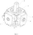
FIG. 1 is a schematic isometric view of a Hall joystick according to one embodiment. -
FIG. 2 is a planar cross-sectional view of the Hall joystick according to one embodiment. -
FIG. 3 is an isometric exploded view of the Hall joystick according to one embodiment. -
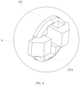
FIG. 4 is an enlarged view of a portion A ofFIG. 1 . -
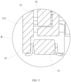
FIG. 5 is an enlarged view of a portion B ofFIG. 2 . -
FIG. 6 is an enlarged view of a portion C ofFIG. 3 . -
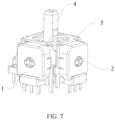
FIG. 7 a schematic isometric view of the Hall joystick viewed from a different perspective. -
FIG. 8 is another isometric exploded view of the Hall joystick according to one embodiment. -
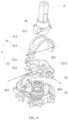
FIG. 9 is another isometric exploded view of the Hall joystick according to one embodiment. -
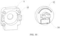
FIG. 10 is an isometric exploded view of a side cap of the Hall joystick according to one embodiment. - The disclosure is illustrated by way of example and not by way of limitation in the figures of the accompanying drawings, in which like reference numerals indicate similar elements. It should be noted that references to "an" or "one" embodiment in this disclosure are not necessarily to the same embodiment, and such references can mean "at least one" embodiment.
- Referring to
FIGS. 1-3 ,7 , and10 , in one embodiment, an integrated joystick with Hall elements may include areturn spring 52, a transmission member 3 (seeFIG. 9 ), afirst side cap 1, asecond cap 2, astick 4, and amain body 5. Themain body 5 is hollow and includes afirst side surface 501 and asecond side surface 502 that are perpendicular to each other. Thereturn spring 52 is arranged within themain body 5. Thefirst side cap 1 and thesecond cap 2 are respectively fixed to thefist side surface 501 and thesecond side surface 502. Thestick 4 is partly received in themain body 5 and has alower end 401 rotatably connected to themain body 5. A first rotatingmember 12 and a second rotatingmember 22 are rotatably connected to thefirst side cap 1 and thesecond side cap 2. Each of the first rotatingmember 12 and the second rotatingmember 22 includes amagnet 14 attached thereto. Thetransmission member 3 is movably arranged in themain body 5 and connected to thestick 4, the first rotatingmember 12 and the second rotatingmember 22. Thetransmission member 3 is to transmit a rotational motion from thestick 4 to the first rotatingmember 12 and the second rotatingmember 22, which drives the first rotatingmember 12 and the second rotatingmember 22 to rotate with respect to thefirst side cap 1 and thesecond side cap 2, respectively. Afirst Hall element 11 is arranged within thefirst side cap 1, and asecond Hall element 21 is arranged within the second side cap. In one example not according to the invention, thefirst Hall element 11 may be arranged under themagnet 14 in the first rotatingmember 12, and thesecond Hall element 21 may be arranged under themagnet 14 in the second rotatingmember 22. - In one embodiment, the
return spring 52 is to urge thestick 4 to automatically return to its original position (e.g., a position where thestick 4 is vertical and extends along a vertical line passing through the center of the main body 5) when there is no external force exerted on thestick 4. The configuration above enables themagnet 14 inside the first rotatingmember 12 to rotate and enables themagnet 14 inside the second rotatingmember 22 to rotate through thetransmission member 3. Thefirst Hall element 11 under themagnet 14 inside the first rotatingmember 12 can detect the change in magnetic field caused by the rotation of themagnet 14 inside the first rotatingmember 12. Thesecond Hall element 21 under themagnet 14 inside the second rotatingmember 22 can detect the change in magnetic field caused by the rotation of themagnet 14 inside the second rotatingmember 22. Thefirst Hall element 11 is arranged within thefirst side cap 1, and thesecond Hall element 21 is arranged within thesecond side cap 2. Thefirst Hall element 11 and thesecond Hall element 21 are integrally connected with the corresponding side caps. When assembled on the assembly line, rapid assembling can be achieved by insertion of the pins on thefirst Hall element 11 and thesecond Hall element 21 to a circuit board. It also realizes the non-contact position detection of the joystick, with long service life, high precision and no drift problem. In addition, the manner in which thefirst side cap 1 and thesecond side cap 2 are arranged enables two linear Hall magnetic induction sensors (i.e., the two Hall elements) to detect the position of thestick 4, which has the advantages of simple structure, low power consumption, simple detection operation, and lower cost. - In one embodiment, the internal structures of the
first side cap 1 and thesecond side cap 2 are the same. For example, an in-mold poly-molding process can be used to integrally arrange thefirst Hall element 11 inside thefirst side cap 1, and integrally arrange thesecond Hall element 21 inside thesecond side cap 2. - In one embodiment, the
main body 5 includes therein arotatable post 51. Thespring 52 is arranged around thepost 51. Thestick 4 defines ahollow space 402, and thepost 51 is received in thehollow space 402. An upper end of thereturn spring 52 abuts against thestick 4. Thestick 4 is rotatable together with therotatable post 51 about a lower end of thepost 51 in contact with themain body 5. - The provision of the
post 51 enables thestick 4 to automatically return to its original position (e.g., a position where thestick 4 is vertical and extends along a vertical line passing through the center of the main body 5) quickly when there is no external force exerted on thestick 4, and enables thestick 4 to rotate smoothly. - Referring to
FIG. 9 , in one embodiment, thetransmission member 3 may include afirst transmission member 31 and asecond transmission member 32 that are rotatably connected to themain body 5 and rotatable about twodifferent axes stick 4 is rotatably connected to thesecond transmission member 32, and is rotatable about an axis ofrotation 403. In the embodiment, the axis ofrotation 403 coincides with theaxis 301. In the embodiment, the twoaxes first transmission member 31 may include aU-shaped body 311, and thesecond transmission member 32 may include ahollow body 321 that is formed by four sidewalls connected to one another. In the embodiment, two opposite sidewalls define two throughholes 3211, and thestick 4 includes twoshaft portion 41 that are rotatably received in the two throughholes 3211. Thefirst transmission member 31 defines agroove 313 in theU-shaped body 311. Thestick 4 passes through thehollow body 321 and thegroove 313 and is movable along thegroove 313 when thestick 4 rotates together with thesecond transmission member 32. Thestick 4 is to push thefirst transmission member 31 to rotate when thestick 4 rotates with respect to thesecond transmission member 32. - In one embodiment, the
first transmission member 31 may include afirst connection portion 312 connected to the first rotatingmember 12, and thesecond transmission member 32 includes asecond connection portion 322 connected to the second rotatingmember 22. - In one embodiment, when the
stick 4 rotates about the axis ofrotation 403 that is perpendicular to thefirst side cap 1, thestick 4 will come into contactU-shaped body 311 and push thefirst transmission member 31 to rotate, thereby causing thefirst connection portion 312 to rotate. The first rotatingmember 12 then rotates together with thefirst connection portion 312, thereby causing themagnet 14 within the first rotatingmember 12 to rotate. Thefirst Hall element 11 can detect the change in the magnetic field caused by the rotation of themagnet 14 inside the first rotatingmember 12. - When the
stick 4 is pushed by a user to move in thegroove 313, thesecond transmission member 32 rotates about theaxis 302 that is perpendicular to thesecond side cap 2, thereby causing thesecond connection portion 322 to rotate. The second rotatingmember 22 then rotates together with thesecond connection portion 322, thereby causing themagnet 14 within the second rotatingmember 22 to rotate. Thesecond Hall element 21 can detect the change in the magnetic field caused by the rotation of themagnet 14 inside the second rotatingmember 22. - Since the
first side cap 1 and thesecond side cap 2 are perpendicular to each other, thestick 4 can move to any point in themain body 5 according to the combination and decomposition of the movement. - Referring to
FIG. 5 , in one example not according to the invention, thefirst Hall element 11 is arranged under themagnet 14 within the first rotatingmember 12, and thesecond Hall element 21 is arranged under themagnet 14 within the first rotatingmember 22. - In another embodiment, the
first Hall element 11 is arranged to face a lateral surface of themagnet 14 arranged in the first rotatingmember 12, and thesecond Hall element 21 is arranged to face a lateral surface of the magnet arranged 14 in the second rotatingmember 22. - It should be noted that the
first Hall element 11 and thesecond Hall element 21 can be arranged at different positions with respect to themagnets 14 depending on actual needs. - In one embodiment, the
firs rotating member 12 is detachably connected to thefirst side cap 1, and the second rotatingmember 22 is detachably connected to thesecond side cap 2. - The first rotating
member 12 can be detached from thefirst side cap 1, and the second rotatingmember 22 can be detached from thesecond side cap 2, which is convenient for assembly and disassembly. The first rotatingmember 12 and the second rotatingmember 22 have the same configuration, and thefirst side cap 1 and thesecond side cap 2 have the same configuration. - In one embodiment, the
magnets 14 are rectangular. - In on embodiment, the
first side cap 1 defines a first receiving space 13 (seeFIG. 2 ) to receive the first rotatingmember 12, and thesecond cap 2 defines a second receiving space 1201 (seeFIG. 8 ) to receive the second rotatingmember 22. - In one embodiment, a first protruding portion 122 (see
FIG. 2 ) protrudes from the first rotatingmember 12, and thefirst side cap 1 defines a first throughhole 121 in communication with thefirst receiving space 13. The first protruding portion 122 passes through the first throughhole 121. A second protruding portion 222 (seeFIG. 4 ) protrudes from the second rotatingmember 22, and thesecond side cap 2 defines a second through hole 201 (seeFIG. 3 ) in communication with thesecond receiving space 1201. The second protrudingportion 222 passes through the second throughhole 201. - The first protruding portion 122 includes a fist hook 1222 (see
FIG. 2 ) at an end thereof, and the first hook 1222 extends out of the first throughhole 121 and abuts against thefirst side cap 1. The second protrudingportion 222 includes a second hook 2221 (seeFIGS. 4 and6 ) at an end thereof, and thesecond hook 2221 extends out of the second throughhole 201 and abuts against thesecond side cap 2. - In one embodiment, the first protruding portion 122 defines a first receiving hole 1221 (see
FIG. 3 ), and thefirst connection portion 312 is fit in thereceiving hole 1221 and abuts against the inner surface of the receivinghole 1221. The first protrudingportion 222 defines a second receiving hole 2222 (seeFIG. 8 ), and thesecond connection portion 322 is fit in thesecond receiving hole 2222 and abuts against the inner surface of the second receiving hole. - In one embodiment, the first rotating
member 12 defines a first receiving chamber 123 (seeFIG. 5 ), and the second rotatingmember 22 defines a second receiving chamber 221 (seeFIG. 3 ). Themagnets 14 are arranged in thefirst receiving chamber 123 and thesecond receiving chamber 221. - In one embodiment, the
first side cap 1 defines afirst cavity 15 in communication with thefirst receiving space 13, and thesecond side cap 2 defines a second cavity in communication with the second receiving space. Thefirst Hall element 11 and thesecond Hall element 21 are respectively received in thefirst cavity 15 and the second cavity. - In one example not according to the invention, the
first Hall element 11 is fixed to a PCB surface and located under themagnet 14 inside the first rotatingmember 12, and thesecond Hall element 21 is fixed to the PCB surface and located under themagnet 14 inside the second rotatingmember 22. - The embodiments above are only illustrative for the technical solutions of the present disclosure, rather than limiting the present disclosure. Although the present disclosure is described in detail with reference to the above embodiments, those of ordinary skill in the art should understand that they still can modify the technical solutions described in the foregoing various embodiments, or make equivalent substitutions on partial technical features; however, these modifications or substitutions do not make the nature of the corresponding technical solution depart from the spirit and scope of technical solutions of various embodiments of the present disclosure, and all should be included within the protection scope of the present disclosure.
Claims (12)
- A joystick, comprising:a main body;a joystick arranged on the main body and able to rotate relative to the main body;a first side cap fixedly connected to a first side surface of the main body;a second side cap fixedly connected to a second side surface of the main body;a first rotating member arranged on the first side cap and provided with an inwardly concave first placement groove in a surface facing the first side cap;a second rotating member arranged on the second side cap;a magnet accommodated in the first placement groove and fixedly connected to the first rotating member;another magnet fixedly connected to the second rotating member; anda transmission member arranged on the main body and linked with the joystick to drive the first rotating member and the magnet to rotate relative to the first side cap, and configured to change relative positions of the magnet and a first sensing element; and further configured to drive the second rotating member and the another magnet to rotate relative to the second side cap, and to change relative positions of the another magnet and a second sensing element.
- The joystick according to claim 1, wherein the first rotating member is provided with a first rotating column that is arranged on a same side as the first placement groove and protrudes outward from the first placement groove and the magnet, the first side cap is provided with a first rotating groove, and the first rotating column rotates to cooperate with the first rotating groove and is engaged with the first side cap.
- The joystick according to claim 2, wherein a side of the first side cap facing the main body is provided with a first accommodation cavity communicated with the first rotating groove, and the first rotating member is rotatably accommodated in the first accommodation cavity.
- The joystick according to claim 3, wherein an inwardly concave second placement groove is formed in a surface of the second rotating member facing the second side cap, the another magnet is accommodated in the second placement groove; the second rotating member is provided with a second rotating column that is arranged on a same side as the second placement groove and protrudes outward from the second placement groove and the another magnet, the second side cap is provided with a second rotating groove, and the second rotating column rotates to cooperate with the second rotating groove and is engaged with the second side cap.
- The joystick according to claim 4, wherein a side of the second side cap facing the main body is provided with a second accommodation cavity communicated with the second rotating groove, and the second rotating member is rotatably accommodated in the second accommodation cavity.
- The joystick according to claim 5, wherein the first side cap is provided with a first accommodation groove communicated with the first accommodation cavity, and the first accommodation groove is configured to accommodate the first sensing element and position the first sensing element in a lower part of the magnet; and the second side cap is provided with a second accommodation groove communicated with the second accommodation cavity, and the second accommodation groove is configured to accommodate the second sensing element and position the second sensing element in a lower part of the another magnet.
- The joystick according to claim 6, wherein the first sensing element is provided with a first pin that protrudes from the first placement groove and bends outward, and the second sensing element is provided with a second pin that protrudes from the second placement groove and bends outward.
- The joystick according to claim 1, wherein the transmission member comprises a first transmission member and a second transmission member that are arranged on the main body in a staggered manner, the first transmission member comprises a first rotating shaft protruding from the first side surface and a second rotating shaft protruding from the second side surface, the first rotating shaft passes through the first rotating member and is capable of driving the first rotating member and the magnet to rotate relative to the first side cap, and the second rotating shaft passes through the second rotating member and is capable of driving the second rotating member and the another magnet to rotate relative to the second side cap.
- The joystick according to claim 1, wherein the first side cap and the second side cap are of a same shape, the first rotating member and the second rotating member are of a same shape, and both the magnet and the another magnet are rectangular.
- The joystick according to claim 1, wherein the first sensing element and the second sensing element both are Hall elements.
- The joystick according to claim 10, wherein the first sensing element is integrally connected to the first side cap, and the second sensing element is integrally connected to the second side cap.
- The joystick according to any one of claims 1 to 11, wherein the joystick comprises a hollow movable sleeve arranged inside the main body and a return spring arranged inside the hollow movable sleeve, and both the hollow movable sleeve and the return spring are stretched into the joystick.
Applications Claiming Priority (3)
| Application Number | Priority Date | Filing Date | Title |
|---|---|---|---|
| CN202120831610.1U CN214474694U (en) | 2021-04-21 | 2021-04-21 | A Hall rocker structure |
| CN202120864065.6U CN215084801U (en) | 2021-04-25 | 2021-04-25 | Integrated handle rocker with Hall element |
| EP22168168.7A EP4080317B1 (en) | 2021-04-21 | 2022-04-13 | Hall joystick |
Related Parent Applications (2)
| Application Number | Title | Priority Date | Filing Date |
|---|---|---|---|
| EP22168168.7A Division EP4080317B1 (en) | 2021-04-21 | 2022-04-13 | Hall joystick |
| EP22168168.7A Division-Into EP4080317B1 (en) | 2021-04-21 | 2022-04-13 | Hall joystick |
Publications (2)
| Publication Number | Publication Date |
|---|---|
| EP4582910A2 true EP4582910A2 (en) | 2025-07-09 |
| EP4582910A3 EP4582910A3 (en) | 2026-01-21 |
Family
ID=81308168
Family Applications (2)
| Application Number | Title | Priority Date | Filing Date |
|---|---|---|---|
| EP22168168.7A Active EP4080317B1 (en) | 2021-04-21 | 2022-04-13 | Hall joystick |
| EP25171722.9A Pending EP4582910A3 (en) | 2021-04-21 | 2022-04-13 | Hall joystick |
Family Applications Before (1)
| Application Number | Title | Priority Date | Filing Date |
|---|---|---|---|
| EP22168168.7A Active EP4080317B1 (en) | 2021-04-21 | 2022-04-13 | Hall joystick |
Country Status (4)
| Country | Link |
|---|---|
| US (3) | US12298800B2 (en) |
| EP (2) | EP4080317B1 (en) |
| JP (3) | JP7627952B2 (en) |
| ES (1) | ES3033302T3 (en) |
Families Citing this family (8)
| Publication number | Priority date | Publication date | Assignee | Title |
|---|---|---|---|---|
| US12298800B2 (en) * | 2021-04-21 | 2025-05-13 | Shenzhen Guli Technology Co., Ltd. | Hall joystick |
| CN116382415B (en) * | 2022-03-23 | 2026-02-17 | 光宝科技股份有限公司 | Rocker module |
| WO2023206819A1 (en) * | 2022-04-24 | 2023-11-02 | 深圳市拳霸科技开发有限公司 | Joystick, gamepad and arcade game |
| US20240111004A1 (en) * | 2022-10-03 | 2024-04-04 | Panda Hardware LLC | Hall effect sensor assembly for use with game controller joysticks |
| TWI838040B (en) * | 2022-12-26 | 2024-04-01 | 福華電子股份有限公司 | Multi-directional output device |
| CN219764461U (en) * | 2023-02-08 | 2023-09-29 | 富港电子(昆山)有限公司 | Rocker module |
| JP2025049816A (en) * | 2023-09-22 | 2025-04-04 | アルプスアルパイン株式会社 | Input device |
| US12528010B2 (en) * | 2023-10-30 | 2026-01-20 | Logitech Europe S.A. | Sequential shifter |
Citations (5)
| Publication number | Priority date | Publication date | Assignee | Title |
|---|---|---|---|---|
| WO2001013194A1 (en) | 1999-08-10 | 2001-02-22 | Hosiden Corporation | Multidirectional input device |
| JP3746929B2 (en) | 1999-10-12 | 2006-02-22 | アルプス電気株式会社 | Multi-directional input device |
| CN101315569B (en) | 2007-06-01 | 2010-06-02 | 阿尔卑斯电气株式会社 | Multi-direction input device |
| CN206995811U (en) | 2017-05-15 | 2018-02-13 | 广东控银实业有限公司 | A kind of game paddle rocking bar |
| CN212135269U (en) | 2020-06-17 | 2020-12-11 | 广东控银实业有限公司 | Magnetic induction type rocker device |
Family Cites Families (55)
| Publication number | Priority date | Publication date | Assignee | Title |
|---|---|---|---|---|
| US4660671A (en) * | 1985-10-23 | 1987-04-28 | Trw Inc. | Electric steering gear |
| US4825157A (en) * | 1988-05-16 | 1989-04-25 | Mikan Peter J | Hall-effect controller |
| US5160918A (en) * | 1990-07-10 | 1992-11-03 | Orvitek, Inc. | Joystick controller employing hall-effect sensors |
| US5113714A (en) * | 1991-02-20 | 1992-05-19 | The United States Of America As Represented By The Administrator Of The National Aeronautics & Space Administration | User friendly joystick |
| US5727188A (en) * | 1993-05-10 | 1998-03-10 | Hayes; Charles L. | Flight-control simulator for computer games |
| JP2665313B2 (en) * | 1994-04-22 | 1997-10-22 | 国際電業株式会社 | Reaction force generator |
| CA2167510C (en) * | 1994-05-20 | 2002-02-12 | Kenji Tosaki | A steering wheel control apparatus for a television game machine |
| US5868573A (en) * | 1994-08-15 | 1999-02-09 | Kerby; Robert Anthony | Vehicle control simulator |
| US5829745A (en) * | 1995-03-28 | 1998-11-03 | Home Arcade Systems, Inc. | Video game control unit with self-centering steering wheel |
| US5823876A (en) * | 1996-05-03 | 1998-10-20 | Unbehand; Erick Michael | Steering wheel simulation assembly |
| US5969520A (en) * | 1997-10-16 | 1999-10-19 | Sauer Inc. | Magnetic ball joystick |
| US6020875A (en) * | 1997-10-31 | 2000-02-01 | Immersion Corporation | High fidelity mechanical transmission system and interface device |
| JP3116027B2 (en) * | 1997-12-05 | 2000-12-11 | コナミ株式会社 | Rotary operation device for amusement machine |
| US6373465B2 (en) * | 1998-11-10 | 2002-04-16 | Lord Corporation | Magnetically-controllable, semi-active haptic interface system and apparatus |
| US6283859B1 (en) * | 1998-11-10 | 2001-09-04 | Lord Corporation | Magnetically-controllable, active haptic interface system and apparatus |
| FR2786266B1 (en) * | 1998-11-20 | 2001-01-19 | Moving Magnet Tech | POSITION SENSOR WITH HALL PROBE |
| US6159099A (en) * | 1998-12-08 | 2000-12-12 | Can Technology Co., Ltd. | Photoelectric control unit of a video car-racing game machine |
| JP3657469B2 (en) * | 1999-04-21 | 2005-06-08 | ホシデン株式会社 | Multi-directional input device |
| US6203432B1 (en) * | 1999-05-11 | 2001-03-20 | Madcatz, Inc. | System for adjusting the response characteristic of an electronic game input device |
| US6480183B1 (en) * | 1999-07-23 | 2002-11-12 | Logitech Europe S.A. | Digital joystick using capacitive sensor |
| US20020128064A1 (en) * | 2001-03-06 | 2002-09-12 | Sobota John F. | Game controller |
| ES1049932Y (en) * | 2001-08-21 | 2002-06-01 | Lorenzo Ind Sa | MULTIDIRECTIONAL COMMAND ORGAN. |
| US20030067111A1 (en) * | 2001-10-09 | 2003-04-10 | Logitech Europe S.A. | Game controller lap attachment device |
| JP4200748B2 (en) * | 2002-11-29 | 2008-12-24 | 富士ゼロックス株式会社 | Tactile interface device |
| US7775884B1 (en) * | 2004-04-30 | 2010-08-17 | Activision Publishing, Inc. | Game controller steering wheel and methods therefor |
| FR2876972B1 (en) * | 2004-10-25 | 2006-12-29 | Koyo Steering Europ K S E Soc | METHOD FOR DETERMINING THE ANGULAR POSITION OF THE STEERING WHEEL OF AN ELECTRIC POWER STEERING OF A MOTOR VEHICLE |
| GB0504484D0 (en) * | 2005-03-03 | 2005-04-13 | Ultra Electronics Ltd | Haptic feedback device |
| US20070077783A1 (en) * | 2005-09-30 | 2007-04-05 | Trw Automotive U.S. Llc | Rotary connector system |
| US20070262959A1 (en) * | 2006-05-12 | 2007-11-15 | Industrial Technology Research Institute | Magnetic joystick |
| US8072418B2 (en) * | 2007-05-31 | 2011-12-06 | Disney Enterprises, Inc. | Tactile feedback mechanism using magnets to provide trigger or release sensations |
| US8117364B2 (en) * | 2007-11-13 | 2012-02-14 | Microsoft Corporation | Enhanced protocol and architecture for low bandwidth force feedback game controller |
| DE102008028618B3 (en) * | 2008-06-18 | 2009-11-12 | Ecs Engineered Control Systems Ag | Electromechanical transducer device |
| JP2010035287A (en) * | 2008-07-25 | 2010-02-12 | Hitachi Ltd | Cylindrical linear motor, and electromagnetic suspension and motor-driven power steering device using the same |
| TW201008620A (en) * | 2008-08-22 | 2010-03-01 | Kye Systems Corp | Structure of manipulation input device |
| CN201323154Y (en) * | 2008-10-22 | 2009-10-07 | 富士康(昆山)电脑接插件有限公司 | Polydirectional switch |
| US8004277B2 (en) * | 2008-12-30 | 2011-08-23 | Honeywell International Inc. | Rotary position sensing apparatus |
| FR2940846B1 (en) * | 2009-01-05 | 2011-03-18 | Guillemot Corp | DEVICE FOR DETECTING THE MOTION OF A HALL EFFECT SHAFT, MANUFACTURING METHOD AND HANDLE THEREFOR |
| US9870021B2 (en) * | 2009-04-15 | 2018-01-16 | SeeScan, Inc. | Magnetic manual user interface devices |
| US8920240B2 (en) * | 2010-04-19 | 2014-12-30 | Guillemot Corporation S.A. | Directional game controller |
| FR2959942B1 (en) * | 2010-05-12 | 2013-06-14 | Guillemot Corp | STEERING COLUMN CONTROLLER |
| CN202423092U (en) * | 2011-11-29 | 2012-09-05 | 郭士秋 | A non-contact game machine magnetoelectric joystick |
| CN102568906A (en) | 2011-11-29 | 2012-07-11 | 郭士秋 | A non-contact game machine magnetoelectric joystick |
| JP5955556B2 (en) * | 2011-12-29 | 2016-07-20 | 株式会社ソニー・インタラクティブエンタテインメント | Operating element and operating device |
| US8834272B2 (en) * | 2012-09-28 | 2014-09-16 | Wms Gaming, Inc. | Dynamically reconfigurable joystick |
| JP5956917B2 (en) * | 2012-12-06 | 2016-07-27 | アルプス電気株式会社 | Multi-directional input device |
| CN204215369U (en) * | 2014-11-14 | 2015-03-18 | 郭士秋 | A kind of contactless rocking bar |
| CN205609414U (en) | 2016-04-25 | 2016-09-28 | 东莞福哥电子有限公司 | An improved 3D rocker device with high return precision |
| WO2018184386A1 (en) | 2017-04-05 | 2018-10-11 | 广东升威电子制品有限公司 | Multi-directional rocker regulating device having improved structure |
| DE102018113280B4 (en) * | 2017-06-07 | 2021-01-14 | Methode Electronics Malta Ltd. | Joystick for turning detection |
| CN206996811U (en) | 2017-07-07 | 2018-02-13 | 山东农业大学 | Rubbish pre-processing device for rural area organic waste compost |
| WO2019067483A1 (en) * | 2017-09-27 | 2019-04-04 | Tactical Haptics, Inc. | Reconfigurable controller devices, systems, and methods |
| JP2020118469A (en) * | 2019-01-18 | 2020-08-06 | 艾礼富▲電▼子(深▲セン▼)有限公司Aleph Electronics(Shenzhen)Co.,Ltd | Magnetic field detection device using hall element or hall IC and proximity sensor using magnetic field detection device |
| DE102019133126A1 (en) * | 2019-12-05 | 2021-06-10 | Methode Electronics Malta Ltd. | Joystick comprising a lever and a housing |
| CN112490053B (en) * | 2020-11-19 | 2024-07-02 | 深圳市致尚科技股份有限公司 | Multidirectional input device and game machine |
| US12298800B2 (en) * | 2021-04-21 | 2025-05-13 | Shenzhen Guli Technology Co., Ltd. | Hall joystick |
-
2022
- 2022-04-07 US US17/715,063 patent/US12298800B2/en active Active
- 2022-04-13 EP EP22168168.7A patent/EP4080317B1/en active Active
- 2022-04-13 ES ES22168168T patent/ES3033302T3/en active Active
- 2022-04-13 EP EP25171722.9A patent/EP4582910A3/en active Pending
- 2022-04-18 JP JP2022068136A patent/JP7627952B2/en active Active
-
2025
- 2025-01-20 JP JP2025008110A patent/JP2025061507A/en active Pending
- 2025-01-20 JP JP2025008113A patent/JP2025061508A/en active Pending
- 2025-04-01 US US19/097,836 patent/US20250231577A1/en active Pending
- 2025-04-01 US US19/097,828 patent/US20250231576A1/en active Pending
Patent Citations (5)
| Publication number | Priority date | Publication date | Assignee | Title |
|---|---|---|---|---|
| WO2001013194A1 (en) | 1999-08-10 | 2001-02-22 | Hosiden Corporation | Multidirectional input device |
| JP3746929B2 (en) | 1999-10-12 | 2006-02-22 | アルプス電気株式会社 | Multi-directional input device |
| CN101315569B (en) | 2007-06-01 | 2010-06-02 | 阿尔卑斯电气株式会社 | Multi-direction input device |
| CN206995811U (en) | 2017-05-15 | 2018-02-13 | 广东控银实业有限公司 | A kind of game paddle rocking bar |
| CN212135269U (en) | 2020-06-17 | 2020-12-11 | 广东控银实业有限公司 | Magnetic induction type rocker device |
Also Published As
| Publication number | Publication date |
|---|---|
| US12298800B2 (en) | 2025-05-13 |
| JP2025061507A (en) | 2025-04-10 |
| US20220342438A1 (en) | 2022-10-27 |
| ES3033302T3 (en) | 2025-08-01 |
| EP4080317A1 (en) | 2022-10-26 |
| JP2025061508A (en) | 2025-04-10 |
| US20250231576A1 (en) | 2025-07-17 |
| US20250231577A1 (en) | 2025-07-17 |
| EP4080317C0 (en) | 2025-06-04 |
| JP7627952B2 (en) | 2025-02-07 |
| JP2022166831A (en) | 2022-11-02 |
| EP4582910A3 (en) | 2026-01-21 |
| EP4080317B1 (en) | 2025-06-04 |
Similar Documents
| Publication | Publication Date | Title |
|---|---|---|
| EP4080317B1 (en) | Hall joystick | |
| WO2022227064A1 (en) | Integrated gamepad rocker having hall elements | |
| CN204792582U (en) | New Game Joystick Switches | |
| US8608565B2 (en) | Operating device for game machine | |
| US10770247B1 (en) | Varistor type multi-directional input device | |
| EP1126354B1 (en) | Multidirectional input device | |
| US9421452B2 (en) | Device with multi-directional moving members | |
| CN215025936U (en) | Gear-adjusting rocker device and game equipment thereof | |
| KR930004013Y1 (en) | X-Y direction input device | |
| JP2018532234A (en) | Piezoresistive multidirectional input device | |
| KR100420239B1 (en) | Multi-directional input appratus | |
| US12277279B2 (en) | Multi-directional output device | |
| CN220691306U (en) | A multi-directional handle rocker and hand crank device | |
| EP3962614B1 (en) | Multiaxis manipulation control device | |
| KR100645846B1 (en) | Integrated volume multi-directional input device | |
| JP2001005545A (en) | Multi-directional inputting device | |
| CN111584290A (en) | Two-axis operating rod based on Hall sensor | |
| WO2020027093A1 (en) | Push-button switch | |
| CN223055064U (en) | Game control equipment | |
| CN219072039U (en) | Rocker of game machine | |
| CN111324171B (en) | foot control | |
| CN219963905U (en) | Game paddle button structure and game paddle | |
| KR20060125601A (en) | Abdominal diet exercise | |
| US20140224627A1 (en) | Thin profile cam switch assemblies | |
| US20020186205A1 (en) | Volume-integral type multi directional input apparatus |
Legal Events
| Date | Code | Title | Description |
|---|---|---|---|
| PUAI | Public reference made under article 153(3) epc to a published international application that has entered the european phase |
Free format text: ORIGINAL CODE: 0009012 |
|
| STAA | Information on the status of an ep patent application or granted ep patent |
Free format text: STATUS: REQUEST FOR EXAMINATION WAS MADE |
|
| 17P | Request for examination filed |
Effective date: 20250522 |
|
| AC | Divisional application: reference to earlier application |
Ref document number: 4080317 Country of ref document: EP Kind code of ref document: P |
|
| AK | Designated contracting states |
Kind code of ref document: A2 Designated state(s): AL AT BE BG CH CY CZ DE DK EE ES FI FR GB GR HR HU IE IS IT LI LT LU LV MC MK MT NL NO PL PT RO RS SE SI SK SM TR |
|
| REG | Reference to a national code |
Ref country code: DE Ref legal event code: R079 Free format text: PREVIOUS MAIN CLASS: G06F0003033800 Ipc: G05G0009047000 |
|
| PUAL | Search report despatched |
Free format text: ORIGINAL CODE: 0009013 |
|
| AK | Designated contracting states |
Kind code of ref document: A3 Designated state(s): AL AT BE BG CH CY CZ DE DK EE ES FI FR GB GR HR HU IE IS IT LI LT LU LV MC MK MT NL NO PL PT RO RS SE SI SK SM TR |
|
| RIC1 | Information provided on ipc code assigned before grant |
Ipc: G05G 9/047 20060101AFI20251218BHEP Ipc: G06F 3/03 20060101ALI20251218BHEP Ipc: A63F 13/24 20140101ALI20251218BHEP Ipc: A63F 13/98 20140101ALI20251218BHEP |