EP4582833A1 - Device and method for simulating an rf reflective object - Google Patents
Device and method for simulating an rf reflective object Download PDFInfo
- Publication number
- EP4582833A1 EP4582833A1 EP24209335.9A EP24209335A EP4582833A1 EP 4582833 A1 EP4582833 A1 EP 4582833A1 EP 24209335 A EP24209335 A EP 24209335A EP 4582833 A1 EP4582833 A1 EP 4582833A1
- Authority
- EP
- European Patent Office
- Prior art keywords
- signal
- parameters
- dut
- simulating
- variation
- Prior art date
- Legal status (The legal status is an assumption and is not a legal conclusion. Google has not performed a legal analysis and makes no representation as to the accuracy of the status listed.)
- Granted
Links
Images

Classifications
-
- G—PHYSICS
- G01—MEASURING; TESTING
- G01S—RADIO DIRECTION-FINDING; RADIO NAVIGATION; DETERMINING DISTANCE OR VELOCITY BY USE OF RADIO WAVES; LOCATING OR PRESENCE-DETECTING BY USE OF THE REFLECTION OR RERADIATION OF RADIO WAVES; ANALOGOUS ARRANGEMENTS USING OTHER WAVES
- G01S13/00—Systems using the reflection or reradiation of radio waves, e.g. radar systems; Analogous systems using reflection or reradiation of waves whose nature or wavelength is irrelevant or unspecified
- G01S13/88—Radar or analogous systems specially adapted for specific applications
- G01S13/93—Radar or analogous systems specially adapted for specific applications for anti-collision purposes
- G01S13/931—Radar or analogous systems specially adapted for specific applications for anti-collision purposes of land vehicles
-
- G—PHYSICS
- G01—MEASURING; TESTING
- G01S—RADIO DIRECTION-FINDING; RADIO NAVIGATION; DETERMINING DISTANCE OR VELOCITY BY USE OF RADIO WAVES; LOCATING OR PRESENCE-DETECTING BY USE OF THE REFLECTION OR RERADIATION OF RADIO WAVES; ANALOGOUS ARRANGEMENTS USING OTHER WAVES
- G01S7/00—Details of systems according to groups G01S13/00, G01S15/00, G01S17/00
- G01S7/02—Details of systems according to groups G01S13/00, G01S15/00, G01S17/00 of systems according to group G01S13/00
- G01S7/40—Means for monitoring or calibrating
- G01S7/4052—Means for monitoring or calibrating by simulation of echoes
- G01S7/4082—Means for monitoring or calibrating by simulation of echoes using externally generated reference signals, e.g. via remote reflector or transponder
-
- G—PHYSICS
- G01—MEASURING; TESTING
- G01S—RADIO DIRECTION-FINDING; RADIO NAVIGATION; DETERMINING DISTANCE OR VELOCITY BY USE OF RADIO WAVES; LOCATING OR PRESENCE-DETECTING BY USE OF THE REFLECTION OR RERADIATION OF RADIO WAVES; ANALOGOUS ARRANGEMENTS USING OTHER WAVES
- G01S7/00—Details of systems according to groups G01S13/00, G01S15/00, G01S17/00
- G01S7/02—Details of systems according to groups G01S13/00, G01S15/00, G01S17/00 of systems according to group G01S13/00
- G01S7/40—Means for monitoring or calibrating
-
- G—PHYSICS
- G01—MEASURING; TESTING
- G01S—RADIO DIRECTION-FINDING; RADIO NAVIGATION; DETERMINING DISTANCE OR VELOCITY BY USE OF RADIO WAVES; LOCATING OR PRESENCE-DETECTING BY USE OF THE REFLECTION OR RERADIATION OF RADIO WAVES; ANALOGOUS ARRANGEMENTS USING OTHER WAVES
- G01S7/00—Details of systems according to groups G01S13/00, G01S15/00, G01S17/00
- G01S7/02—Details of systems according to groups G01S13/00, G01S15/00, G01S17/00 of systems according to group G01S13/00
- G01S7/40—Means for monitoring or calibrating
- G01S7/4052—Means for monitoring or calibrating by simulation of echoes
-
- G—PHYSICS
- G01—MEASURING; TESTING
- G01S—RADIO DIRECTION-FINDING; RADIO NAVIGATION; DETERMINING DISTANCE OR VELOCITY BY USE OF RADIO WAVES; LOCATING OR PRESENCE-DETECTING BY USE OF THE REFLECTION OR RERADIATION OF RADIO WAVES; ANALOGOUS ARRANGEMENTS USING OTHER WAVES
- G01S7/00—Details of systems according to groups G01S13/00, G01S15/00, G01S17/00
- G01S7/02—Details of systems according to groups G01S13/00, G01S15/00, G01S17/00 of systems according to group G01S13/00
- G01S7/40—Means for monitoring or calibrating
- G01S7/4052—Means for monitoring or calibrating by simulation of echoes
- G01S7/4056—Means for monitoring or calibrating by simulation of echoes specially adapted to FMCW
-
- G—PHYSICS
- G01—MEASURING; TESTING
- G01S—RADIO DIRECTION-FINDING; RADIO NAVIGATION; DETERMINING DISTANCE OR VELOCITY BY USE OF RADIO WAVES; LOCATING OR PRESENCE-DETECTING BY USE OF THE REFLECTION OR RERADIATION OF RADIO WAVES; ANALOGOUS ARRANGEMENTS USING OTHER WAVES
- G01S7/00—Details of systems according to groups G01S13/00, G01S15/00, G01S17/00
- G01S7/02—Details of systems according to groups G01S13/00, G01S15/00, G01S17/00 of systems according to group G01S13/00
- G01S7/40—Means for monitoring or calibrating
- G01S7/4052—Means for monitoring or calibrating by simulation of echoes
- G01S7/4082—Means for monitoring or calibrating by simulation of echoes using externally generated reference signals, e.g. via remote reflector or transponder
- G01S7/4095—Means for monitoring or calibrating by simulation of echoes using externally generated reference signals, e.g. via remote reflector or transponder the external reference signals being modulated, e.g. rotating a dihedral reflector or modulating a transponder for simulation of a Doppler echo
Definitions
- the simulation parameters may comprise one or more of: a delay of the object in accordance with a simulated radial distance of the object relative to the DUT, a frequency shift of the object in accordance with a simulated radial velocity of the object relative to the DUT, and an attenuation of the object in accordance with a simulated cross-sectional area of the object and the simulated radial distance of the object relative to the DUT.
- the receiver 11 is configured for receiving an RF signal 2, preferably from a device under test, DUT 3 or the input 11 is configured for receiving an RF signal 2, preferably from an RF source such as an RF vector signal generator.
- the RF signal 2 may be a radar signal.
- the receiver 11 may comprise a radar receiver.
- the simulation parameters 132 may comprise one or more of: a delay ⁇ t of the object in accordance with a simulated radial distance r of the object relative to the DUT 3, a frequency shift ⁇ f D of the object in accordance with a simulated radial velocity v of the object relative to the DUT 3 (i.e., a Doppler frequency shift), and an attenuation ⁇ of the object in accordance with a simulated cross-sectional area ⁇ of the object - i.e., a radar cross-section, RCS - and the simulated radial distance r of the object relative to the DUT 3.
- the adapted RF signal 2' may be a radar signal, too.
- the transmitter 14 may comprise a radar transmitter.
- the method 4 comprises a step of receiving 41 an RF signal 2 from a device under test, DUT 3.
- the method 4 further comprises a step of transmitting 44 the adapted RF signal 2'to the DUT 3, the adapted RF signal 2 ' simulating a reflection of the RF signal 2 by the object.
- the method 4 may be performed by a device 1 for simulating an RF reflective object according to the first aspect.
Landscapes
- Engineering & Computer Science (AREA)
- Radar, Positioning & Navigation (AREA)
- Remote Sensing (AREA)
- Physics & Mathematics (AREA)
- Computer Networks & Wireless Communication (AREA)
- General Physics & Mathematics (AREA)
- Electromagnetism (AREA)
- Radar Systems Or Details Thereof (AREA)
Abstract
Description
- The present disclosure relates to radio detection and ranging (RADAR) echo generation, and in particular to devices and methods for simulating an RF reflective object and to devices for simulating RF fading.
- Radar sensors usually change their signal parameters during object detection depending on the current task in order to gain either improved range resolution or maximum visible distance.
- Until now, the signal parameters such as a center frequency are pre-configured manually and the object resp. channel simulation has to be parametrized accordingly. Any deviations from the pre-configured signal parameters caused by a measurement setup or tolerances of the radar sensor device under test (DUT) require manual correction. This applies to simulation of RF reflective objects e.g. in front of the DUT as well as to simulation of RF fading in between a tester and the DUT.
- It is an object to overcome the above-mentioned and other drawbacks.
- The foregoing and other objects are achieved by the features of the independent claims. Further implementation forms are apparent from the dependent claims, the description and the figures.
- According to a first aspect of the present disclosure, a device is provided for simulating an RF reflective object. The device comprises: a receiver, configured for receiving an RF signal from a device under test, DUT; a signal variation parameter estimation circuit, configured for estimating, based on an analysis of the RF signal, one or more signal variation-over-time parameters of the RF signal; one or more signal parameter adaptation circuits, configured for adapting one or more signal parameters of the RF signal in real-time as a function of one or more simulation parameters, and the one or more estimated signal variation-over-time parameters of the RF signal; and a transmitter, configured for transmitting the adapted RF signal to the DUT, the adapted RF signal simulating a reflection of the RF signal by the object.
- According to a second aspect of the present disclosure, a device is provided for simulating RF fading. The device comprises: an input, configured for receiving an RF signal; a signal variation parameter estimation circuit, configured for estimating, based on an analysis of the RF signal, one or more signal variation-over-time parameters of the RF signal; one or more signal parameter adaptation circuits, configured for adapting one or more signal parameters of the RF signal in real-time as a function of one or more simulation parameters, and the one or more estimated signal variation-over-time parameters of the RF signal; and a transmitter, configured for transmitting the adapted RF signal to a device under test, DUT, the adapted RF signal simulating an RF fading of the RF signal.
- The RF signal and the adapted RF signal may be radar signals.
- The signal parameters of the RF signal may comprise one or more of: a timing of the RF signal, a frequency of the RF signal, and an average power of the RF signal.
- The estimated signal variation-over-time parameters of the RF signal may comprise an estimated frequency offset of the RF signal.
- The signal parameter adaptation circuits may respectively be configured for adapting one of the signal parameters of the RF signal.
- The simulation parameters may comprise one or more of: a delay of the object in accordance with a simulated radial distance of the object relative to the DUT, a frequency shift of the object in accordance with a simulated radial velocity of the object relative to the DUT, and an attenuation of the object in accordance with a simulated cross-sectional area of the object and the simulated radial distance of the object relative to the DUT.
- The simulation parameters may further comprise one of: a zero-mean Gaussian random path attenuation between the object and the DUT, and a power delay profile comprising attenuation values and delay values for a plurality of taps of a tapped delay line fading model.
- The signal parameter adaptation circuits may comprise one or more of: a tunable delay circuit for delaying the RF signal in accordance with the delay of the object, a tunable frequency shift circuit for shifting the frequency of the RF signal in accordance with the frequency shift of the object and the estimated frequency offset of the RF signal, and a tunable attenuation circuit for attenuating the RF signal in accordance with the attenuation of the object.
- The signal parameter adaptation circuits may further comprise one of: a fading emulation circuit for attenuating the RF signal in accordance with the zero-mean Gaussian random path attenuation, and a fading emulation circuit for attenuating and delaying the RF signal in accordance with the power delay profile.
- The device may further comprise a user notification circuit for notifying a user of the device of the estimated signal variation-over-time parameters of the RF signal relative to corresponding user-provided signal parameters of the RF signal.
- According to a third aspect of the present disclosure, a measurement system is provided, comprising a device for simulating an RF reflective object according to the first aspect or a device for simulating RF fading according to the second aspect; and a device under test, DUT, being a radar sensor preferably for automotive applications.
- According to a fourth aspect of the present disclosure, a method is provided for simulating an RF reflective object. The method comprises: receiving an RF signal from a device under test, DUT; estimating, based on an analysis of the RF signal, one or more signal variation-over-time parameters of the RF signal; adapting one or more signal parameters of the RF signal in real-time as a function of one or more simulation parameters and the one or more estimated signal variation-over-time parameters of the RF signal; and transmitting the adapted RF signal to the DUT, the adapted RF signal simulating a reflection of the RF signal by the object.
- The method may be performed by a device for simulating an RF reflective object according to the first aspect.
- The present disclosure provides automatic analysis of signal parameters and automatic adaptation of simulation parameters of objects which depend on the signal parameters and would have to be corrected manually otherwise.
- The above-described aspects and implementations will now be explained with reference to the accompanying drawings, in which the same or similar reference numerals designate the same or similar elements.
- The features of these aspects and implementations may be combined with each other unless specifically stated otherwise.
- The drawings are to be regarded as being schematic representations, and elements illustrated in the drawings are not necessarily shown to scale. Rather, the various elements are represented such that their function and general purpose become apparent to those skilled in the art.
-
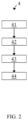
FIG. 1 illustrates a measurement system including a device in accordance with the present disclosure; and -
FIG. 2 illustrates a method in accordance with the present disclosure. -
FIG. 1 illustrates ameasurement system 1, 1A, 3 including a device 1, 1A in accordance with the present disclosure. - The
measurement system 1, 1A, 3 comprises a device 1 for simulating an RF reflective object according to the first aspect or a device 1A for simulating RF fading according to the second aspect, and a device under test,DUT 3. TheDUT 3 may be a radar sensor, preferably for automotive applications. - The device 1, 1A comprises a receiver or
input 11, a signal variationparameter estimation circuit 12, one or more signalparameter adaptation circuits 13, 13A-Z, atransmitter 14, and may comprise auser notification circuit 15. - The
receiver 11 is configured for receiving anRF signal 2, preferably from a device under test,DUT 3 or theinput 11 is configured for receiving anRF signal 2, preferably from an RF source such as an RF vector signal generator. In particular, theRF signal 2 may be a radar signal. Likewise, thereceiver 11 may comprise a radar receiver. - The signal variation
parameter estimation circuit 12 is configured for estimating, based on an analysis of theRF signal 2, one or more signal variation-over-timeparameters 131 of theRF signal 2. - In particular, the estimated signal variation-over-time
parameters 131 of theRF signal 2 may comprise an estimated frequency offset Δf of theRF signal 2, either relative to the (given) frequency f0 of the RF signal 2 (i.e., Δf) or implicitly (i.e., f0 +Δf). Correspondingly, the signal variationparameter estimation circuit 12 may, for instance, comprise an analog-to-digital converter, ADC, a digital down converter, DDC, and a Fast Fourier Transform, FFT, analyzer implemented as a digital circuit (e.g., ASIC, FPGA, DSP or the like). - The one or more signal
parameter adaptation circuits 13, 13A-Z are configured for adapting one or more signal parameters of theRF signal 2 in real-time as a function of one ormore simulation parameters 132 and the one or more estimated signal variation-over-timeparameters 131 of theRF signal 2. - The signal parameters of the
RF signal 2 may comprise one or more of: a timing of theRF signal 2, a frequency f0 of theRF signal 2, and an average power of theRF signal 2. - A timing as used herein may refer to a temporal occurrence (e.g., start time, end time) of a pulse of the
RF signal 2. - A power as used herein may refer to an average power (in mW) or power level (in dBm, with reference to 1 mW) of the
RF signal 2. - A frequency as used herein may refer to a center frequency f0 of the
RF signal 2. - The
simulation parameters 132 may comprise one or more of: a delay Δt of the object in accordance with a simulated radial distance r of the object relative to theDUT 3, a frequency shift ΔfD of the object in accordance with a simulated radial velocity v of the object relative to the DUT 3 (i.e., a Doppler frequency shift), and an attenuation α of the object in accordance with a simulated cross-sectional area σ of the object - i.e., a radar cross-section, RCS - and the simulated radial distance r of the object relative to theDUT 3. Thesimulation parameters 132 may further comprise one of a zero-mean Gaussian random path attenuation ε between the object and theDUT 3, and a power delay profile comprising attenuation values αi and delay values τi for a plurality of i taps of a tapped delay line fading model.


- More specifically, the signal
parameter adaptation circuits 13, 13A-Z may comprise one or more of: a tunable delay circuit 13A (e.g., analog tunable delay line or equivalent DSP filter implementation) for delaying theRF signal 2 in accordance with the delay Δt of the object, a tunable frequency shift circuit 13B (e.g., analog complex frequency shifter, or equivalent DSP filter implementation) for shifting the frequency f0 of theRF signal 2 in accordance with the frequency shift ΔfD of the object and the estimated frequency offset Δf of theRF signal 2, and a tunable attenuation circuit 13Z (e.g., analog variable attenuator, or equivalent DSP filter implementation) for attenuating theRF signal 2 in accordance with the attenuation α of the object. The signalparameter adaptation circuits 13, 13A-Z may further comprise one of: a fading emulation circuit 13C (e.g, a DSP filter implementation) for attenuating theRF signal 2 in accordance with the zero-mean Gaussian random path attenuation ε, and a fading emulation circuit 13C (e.g, a DSP filter implementation) for attenuating and delaying theRF signal 2 in accordance with the power delay profile. - Shifting the frequency f0 → f0 +Δf of the
RF signal 2 in accordance with the frequency shift ΔfD (due to the simulated radial velocity v) of the object and the estimated frequency offset Δf of theRF signal 2 may be outlined as follows:
- In other words, the estimated frequency offset Δf of the frequency f0 of the
RF signal 2 yields a corresponding offset
- The
transmitter 14 is configured for transmitting the adapted RF signal 2' to theDUT 3, wherein the adapted RF signal 2' simulates a reflection of theRF signal 2 by the object or an RF fading of theRF signal 2. - Evidently, the adapted RF signal 2' may be a radar signal, too. Accordingly, the
transmitter 14 may comprise a radar transmitter. - The
receiver 11 and thetransmitter 12 may form part of atransceiver FIG. 1 ) mediating between wireline transmission and wireless transmission of the RF signals 2, 2 '. - The
user notification circuit 15, if any, is configured for notifying a user of the device 1, 1A of the estimated signal variation-over-time parameters 131 of theRF signal 2 relative to corresponding user-providedsignal parameters 121 of theRF signal 2. In other words, the signal variation-over-time parameters 131 of theRF signal 2 may be used to distinguish between the wanted RF signal and interferers. - Also the user-provided
signal parameters 121 of theRF signal 2 may comprise one or more of: a timing of theRF signal 2, a frequency f0 of theRF signal 2, and an average power of theRF signal 2. -
FIG. 2 illustrates a method 4 in accordance with the present disclosure. - The method 4 is suitable for simulating an RF reflective object.
- The method 4 comprises a step of receiving 41 an
RF signal 2 from a device under test,DUT 3. - The method 4 further comprises a step of estimating 42, based on an analysis of the
RF signal 2, one or more signal variation-over-time parameters 131 of theRF signal 2. - The method 4 further comprises a step of adapting 43 one or more signal parameters of the
RF signal 2 in real-time as a function of one ormore simulation parameters 132 and the one or more estimated signal variation-over-time parameters 131 of theRF signal 2. - The method 4 further comprises a step of transmitting 44 the adapted RF signal 2'to the
DUT 3, the adapted RF signal 2 ' simulating a reflection of theRF signal 2 by the object. - The method 4 may be performed by a device 1 for simulating an RF reflective object according to the first aspect.
- The technical effects and advantages described above in relation with the device 1 of the first aspect equally apply to the method 4 of the third aspect having corresponding features.
Claims (14)
- A device (1) for simulating an RF reflective object, the device (1) comprising- a receiver (11), configured for receiving an RF signal from a device under test, DUT;- a signal variation parameter estimation circuit (12), configured for estimating, based on an analysis of the RF signal, one or more signal variation-over-time parameters of the RF signal;- one or more signal parameter adaptation circuits (13), configured for adapting one or more signal parameters of the RF signal in real-time as a function of one or more simulation parameters, and the one or more estimated signal variation-over-time parameters of the RF signal; and- a transmitter (14), configured for transmitting the adapted RF signal to the DUT, the adapted RF signal simulating a reflection of the RF signal by the object.
- A device for simulating RF fading, the device comprising- an input (11), configured for receiving an RF signal;- a signal variation parameter estimation circuit (12), configured for estimating, based on an analysis of the RF signal, one or more signal variation-over-time parameters of the RF signal;- one or more signal parameter adaptation circuits (13), configured for adapting one or more signal parameters of the RF signal in real-time as a function of one or more simulation parameters, and the one or more estimated signal variation-over-time parameters of the RF signal; and- a transmitter (14), configured for transmitting the adapted RF signal to a Device Under Test, DUT, the adapted RF signal simulating an RF fading of the RF signal.
- The device of claim 1 or claim 2,
the RF signal and the adapted RF signal being radar signals. - The device of any of claims 1 to 3,
the signal parameters of the RF signal comprising one or more of:- a timing of the RF signal,- a frequency of the RF signal, and- an average power of the RF signal. - The device of any of the preceding claims,
the estimated signal variation-over-time parameters of the RF signal comprising:- an estimated frequency offset of the RF signal. - The device of any of the preceding claims,
the signal parameter adaptation circuits (13) respectively being configured for adapting one of the signal parameters of the RF signal. - The device of any of the preceding claims,
the simulation parameters comprising one or more of:- a delay of the object in accordance with a simulated radial distance of the object relative to the DUT,- a frequency shift of the object in accordance with a simulated radial velocity of the object relative to the DUT, and- an attenuation of the object in accordance with a simulated cross-sectional area of the object and the simulated radial distance of the object relative to the DUT. - The device of claim 7,
the simulation parameters further comprising one of:- a zero-mean Gaussian random path attenuation between the object and the DUT, and- a power delay profile comprising attenuation values and delay values for a plurality of taps of a tapped delay line fading model. - The device of claim 7 or 8,
the signal parameter adaptation circuits comprising one or more of:- a tunable delay circuit for delaying the RF signal in accordance with the delay of the object,- a tunable frequency shift circuit for shifting the frequency of the RF signal in accordance with the frequency shift of the object and the estimated frequency offset of the RF signal, and- a tunable attenuation circuit for attenuating the RF signal in accordance with the attenuation of the object. - The device of claim 8,
the signal parameter adaptation circuits (13) further comprising one of:- a fading emulation circuit for attenuating the RF signal in accordance with the zero-mean Gaussian random path attenuation, and- a fading emulation circuit for attenuating and delaying the RF signal in accordance with the power delay profile. - The device of any of the preceding claims, further comprising- a user notification circuit (15) for notifying a user of the device of the estimated signal variation-over-time parameters of the RF signal relative to corresponding user-provided signal parameters of the RF signal.
- A measurement system, comprising- a device (1) according to any of the preceding claims; and- a device under test, DUT, being a radar sensor preferably for automotive applications.
- A method for simulating an RF reflective object, the method comprising- receiving (11) an RF signal from a device under test, DUT;- estimating (12), based on an analysis of the RF signal, one or more signal variation-over-time parameters of the RF signal;- adapting (13) one or more signal parameters of the RF signal in real-time as a function of one or more simulation parameters and the one or more estimated signal variation-over-time parameters of the RF signal; and- transmitting (14) the adapted RF signal to the DUT, the adapted RF signal simulating a reflection of the RF signal by the object.
- The method of claim 13,
being performed by a device (1) for simulating an RF reflective object according to any of claims 1 to 11.
Applications Claiming Priority (1)
| Application Number | Priority Date | Filing Date | Title |
|---|---|---|---|
| US18/403,300 US20250216510A1 (en) | 2024-01-03 | 2024-01-03 | Device and method for simulating an rf reflective object |
Publications (2)
| Publication Number | Publication Date |
|---|---|
| EP4582833A1 true EP4582833A1 (en) | 2025-07-09 |
| EP4582833B1 EP4582833B1 (en) | 2026-08-19 |
Family
ID=93333890
Family Applications (1)
| Application Number | Title | Priority Date | Filing Date |
|---|---|---|---|
| EP24209335.9A Active EP4582833B1 (en) | 2024-01-03 | 2024-10-29 | Device and method for simulating an rf reflective object |
Country Status (3)
| Country | Link |
|---|---|
| US (1) | US20250216510A1 (en) |
| EP (1) | EP4582833B1 (en) |
| CN (1) | CN120254779A (en) |
Citations (2)
| Publication number | Priority date | Publication date | Assignee | Title |
|---|---|---|---|---|
| EP3812790A1 (en) * | 2019-10-24 | 2021-04-28 | Perisens GmbH | Device, system and method for calibration of radar target simulators |
| EP3982148A1 (en) * | 2020-10-06 | 2022-04-13 | Rohde & Schwarz GmbH & Co. KG | Radar target simulator with continuous distance emulation and corresponding simulation method |
Family Cites Families (3)
| Publication number | Priority date | Publication date | Assignee | Title |
|---|---|---|---|---|
| CA2757315A1 (en) * | 2009-06-03 | 2010-12-09 | Elektrobit System Test Oy | Over-the-air test |
| US8718122B2 (en) * | 2010-02-18 | 2014-05-06 | Azimuth Systems, Inc. | Testing performance of a wireless device |
| JP7724294B2 (en) * | 2021-01-28 | 2025-08-15 | キーサイト テクノロジーズ, インク. | System and method for emulating echo signals from an emulated target with reduced interference from reflections |
-
2024
- 2024-01-03 US US18/403,300 patent/US20250216510A1/en active Pending
- 2024-10-29 EP EP24209335.9A patent/EP4582833B1/en active Active
- 2024-11-27 CN CN202411711868.2A patent/CN120254779A/en active Pending
Patent Citations (2)
| Publication number | Priority date | Publication date | Assignee | Title |
|---|---|---|---|---|
| EP3812790A1 (en) * | 2019-10-24 | 2021-04-28 | Perisens GmbH | Device, system and method for calibration of radar target simulators |
| EP3982148A1 (en) * | 2020-10-06 | 2022-04-13 | Rohde & Schwarz GmbH & Co. KG | Radar target simulator with continuous distance emulation and corresponding simulation method |
Non-Patent Citations (2)
| Title |
|---|
| BOKOV ALEXANDER ET AL: "Improving the Accuracy of Digital Simulation of the Radio Signal Propagation Delay", 2019 RADIATION AND SCATTERING OF ELECTROMAGNETIC WAVES (RSEMW), IEEE, 24 June 2019 (2019-06-24), pages 348 - 351, XP033594648, DOI: 10.1109/RSEMW.2019.8792794 * |
| JAIN RAJ: "Channel Models A Tutorial", 21 February 2007 (2007-02-21), XP093251805, Retrieved from the Internet <URL:https://www.cse.wustl.edu/~jain/cse574-08/ftp/channel_model_tutorial.pdf?utm_source=chatgpt.com> [retrieved on 20250218] * |
Also Published As
| Publication number | Publication date |
|---|---|
| EP4582833B1 (en) | 2026-08-19 |
| CN120254779A (en) | 2025-07-04 |
| US20250216510A1 (en) | 2025-07-03 |
Similar Documents
| Publication | Publication Date | Title |
|---|---|---|
| US10145949B2 (en) | Radar apparatus | |
| US10557933B2 (en) | Radar device and position-determination method | |
| JP6974813B2 (en) | Measurement of transceiver performance parameters in radar systems | |
| US10473773B2 (en) | Time synchronization of spatially separated radars | |
| US9470784B2 (en) | Radar device | |
| EP3208632B1 (en) | Radar apparatus and radar method | |
| US9733347B2 (en) | Radar apparatus | |
| US20210286049A1 (en) | Noise measurement in a radar system | |
| CN106249066B (en) | Method for calibrating a cable and corresponding measuring device | |
| US6236371B1 (en) | System and method for testing antenna frequency response | |
| US20240295649A1 (en) | Frequency modulated continuous wave radar system with interference mitigation | |
| JP2020165810A (en) | Radar device and radar device interference estimation method | |
| US20250035767A1 (en) | Positioning system and vehicle including positioning system, and positioning method | |
| US20180372839A1 (en) | Apparatus and method of quadrature detection using one mixer without oversampling in a receiver | |
| CN105388463A (en) | Reception signal processing device, radar, and object detection method | |
| US20250216510A1 (en) | Device and method for simulating an rf reflective object | |
| JP3853713B2 (en) | Transmission pulse level correction circuit and correction method, and DME device responder using the same | |
| JP3818204B2 (en) | Radar equipment | |
| Amar et al. | USRP based Implementation of Interference Immune PMCW Radars with Low Sampling rate ADCs | |
| RU2498337C1 (en) | Apparatus for selecting clutter reflections from optically unobservable objects ("angels") in area of "local" objects | |
| EP4542256A1 (en) | Distance measurement device | |
| KR101104560B1 (en) | Speed vehicle detection device and method | |
| Espedalen et al. | Object detection using a software defined radio with FMCW RADAR technology | |
| JP3100467B2 (en) | Millimeter wave radar device | |
| Khokhar et al. | Methodology for Characterization of Navigation Radar Altimeter in Lab |
Legal Events
| Date | Code | Title | Description |
|---|---|---|---|
| PUAI | Public reference made under article 153(3) epc to a published international application that has entered the european phase |
Free format text: ORIGINAL CODE: 0009012 |
|
| STAA | Information on the status of an ep patent application or granted ep patent |
Free format text: STATUS: THE APPLICATION HAS BEEN PUBLISHED |
|
| AK | Designated contracting states |
Kind code of ref document: A1 Designated state(s): AL AT BE BG CH CY CZ DE DK EE ES FI FR GB GR HR HU IE IS IT LI LT LU LV MC ME MK MT NL NO PL PT RO RS SE SI SK SM TR |
|
| STAA | Information on the status of an ep patent application or granted ep patent |
Free format text: STATUS: REQUEST FOR EXAMINATION WAS MADE |
|
| 17P | Request for examination filed |
Effective date: 20260107 |
|
| GRAP | Despatch of communication of intention to grant a patent |
Free format text: ORIGINAL CODE: EPIDOSNIGR1 |
|
| STAA | Information on the status of an ep patent application or granted ep patent |
Free format text: STATUS: GRANT OF PATENT IS INTENDED |
|
| RIC1 | Information provided on ipc code assigned before grant |
Ipc: G01S 7/40 20060101AFI20260430BHEP Ipc: G01S 13/931 20200101ALI20260430BHEP |
|
| INTG | Intention to grant announced |
Effective date: 20260521 |
|
| GRAS | Grant fee paid |
Free format text: ORIGINAL CODE: EPIDOSNIGR3 |
|
| GRAA | (expected) grant |
Free format text: ORIGINAL CODE: 0009210 |
|
| STAA | Information on the status of an ep patent application or granted ep patent |
Free format text: STATUS: THE PATENT HAS BEEN GRANTED |
|
| P01 | Opt-out of the competence of the unified patent court (upc) registered |
Free format text: CASE NUMBER: UPC_APP_0019098_4582833/2026 Effective date: 20260619 |