EP4582768A1 - Boundary line detection device and method - Google Patents
Boundary line detection device and method Download PDFInfo
- Publication number
- EP4582768A1 EP4582768A1 EP23860872.3A EP23860872A EP4582768A1 EP 4582768 A1 EP4582768 A1 EP 4582768A1 EP 23860872 A EP23860872 A EP 23860872A EP 4582768 A1 EP4582768 A1 EP 4582768A1
- Authority
- EP
- European Patent Office
- Prior art keywords
- boundary
- electrode
- temporary
- electrode image
- uncoated portion
- Prior art date
- Legal status (The legal status is an assumption and is not a legal conclusion. Google has not performed a legal analysis and makes no representation as to the accuracy of the status listed.)
- Pending
Links
Images


Classifications
-
- G—PHYSICS
- G06—COMPUTING OR CALCULATING; COUNTING
- G06T—IMAGE DATA PROCESSING OR GENERATION, IN GENERAL
- G06T7/00—Image analysis
- G06T7/10—Segmentation; Edge detection
- G06T7/12—Edge-based segmentation
-
- G—PHYSICS
- G06—COMPUTING OR CALCULATING; COUNTING
- G06T—IMAGE DATA PROCESSING OR GENERATION, IN GENERAL
- G06T7/00—Image analysis
- G06T7/10—Segmentation; Edge detection
- G06T7/13—Edge detection
-
- G—PHYSICS
- G01—MEASURING; TESTING
- G01B—MEASURING LENGTH, THICKNESS OR SIMILAR LINEAR DIMENSIONS; MEASURING ANGLES; MEASURING AREAS; MEASURING IRREGULARITIES OF SURFACES OR CONTOURS
- G01B11/00—Measuring arrangements characterised by the use of optical techniques
- G01B11/02—Measuring arrangements characterised by the use of optical techniques for measuring length, width or thickness
- G01B11/022—Measuring arrangements characterised by the use of optical techniques for measuring length, width or thickness by means of tv-camera scanning
-
- G—PHYSICS
- G01—MEASURING; TESTING
- G01B—MEASURING LENGTH, THICKNESS OR SIMILAR LINEAR DIMENSIONS; MEASURING ANGLES; MEASURING AREAS; MEASURING IRREGULARITIES OF SURFACES OR CONTOURS
- G01B11/00—Measuring arrangements characterised by the use of optical techniques
- G01B11/02—Measuring arrangements characterised by the use of optical techniques for measuring length, width or thickness
- G01B11/028—Measuring arrangements characterised by the use of optical techniques for measuring length, width or thickness by measuring lateral position of a boundary of the object
-
- G—PHYSICS
- G01—MEASURING; TESTING
- G01B—MEASURING LENGTH, THICKNESS OR SIMILAR LINEAR DIMENSIONS; MEASURING ANGLES; MEASURING AREAS; MEASURING IRREGULARITIES OF SURFACES OR CONTOURS
- G01B11/00—Measuring arrangements characterised by the use of optical techniques
- G01B11/02—Measuring arrangements characterised by the use of optical techniques for measuring length, width or thickness
- G01B11/03—Measuring arrangements characterised by the use of optical techniques for measuring length, width or thickness by measuring coordinates of points
-
- G—PHYSICS
- G06—COMPUTING OR CALCULATING; COUNTING
- G06T—IMAGE DATA PROCESSING OR GENERATION, IN GENERAL
- G06T7/00—Image analysis
-
- G—PHYSICS
- G06—COMPUTING OR CALCULATING; COUNTING
- G06T—IMAGE DATA PROCESSING OR GENERATION, IN GENERAL
- G06T7/00—Image analysis
- G06T7/10—Segmentation; Edge detection
- G06T7/136—Segmentation; Edge detection involving thresholding
-
- H—ELECTRICITY
- H01—ELECTRIC ELEMENTS
- H01M—PROCESSES OR MEANS, e.g. BATTERIES, FOR THE DIRECT CONVERSION OF CHEMICAL ENERGY INTO ELECTRICAL ENERGY
- H01M10/00—Secondary cells; Manufacture thereof
- H01M10/04—Construction or manufacture in general
- H01M10/0422—Cells or battery with cylindrical casing
-
- G—PHYSICS
- G01—MEASURING; TESTING
- G01N—INVESTIGATING OR ANALYSING MATERIALS BY DETERMINING THEIR CHEMICAL OR PHYSICAL PROPERTIES
- G01N21/00—Investigating or analysing materials by the use of optical means, i.e. using sub-millimetre waves, infrared, visible or ultraviolet light
- G01N21/84—Systems specially adapted for particular applications
- G01N21/8422—Investigating thin films, e.g. matrix isolation method
- G01N2021/8427—Coatings
- G01N2021/8433—Comparing coated/uncoated parts
-
- G—PHYSICS
- G06—COMPUTING OR CALCULATING; COUNTING
- G06T—IMAGE DATA PROCESSING OR GENERATION, IN GENERAL
- G06T2207/00—Indexing scheme for image analysis or image enhancement
- G06T2207/30—Subject of image; Context of image processing
- G06T2207/30108—Industrial image inspection
-
- Y—GENERAL TAGGING OF NEW TECHNOLOGICAL DEVELOPMENTS; GENERAL TAGGING OF CROSS-SECTIONAL TECHNOLOGIES SPANNING OVER SEVERAL SECTIONS OF THE IPC; TECHNICAL SUBJECTS COVERED BY FORMER USPC CROSS-REFERENCE ART COLLECTIONS [XRACs] AND DIGESTS
- Y02—TECHNOLOGIES OR APPLICATIONS FOR MITIGATION OR ADAPTATION AGAINST CLIMATE CHANGE
- Y02E—REDUCTION OF GREENHOUSE GAS [GHG] EMISSIONS, RELATED TO ENERGY GENERATION, TRANSMISSION OR DISTRIBUTION
- Y02E60/00—Enabling technologies; Technologies with a potential or indirect contribution to GHG emissions mitigation
- Y02E60/10—Energy storage using batteries
Definitions
- the present invention relates to a device and method for detecting boundaries of battery electrodes, and more particularly, to a device and method for detecting boundaries of uncoated portions on electrode images.
- Lithium secondary batteries among secondary batteries are being applied to various industrial fields such as from mobile application devices to automobiles, robots, and energy storage devices, as a response to today's environmental regulations and high oil price issues.
- lithium batteries are generally classified into cylindrical, prismatic, or pouch types depending on the shape of the exterior material in which the electrode assembly is accommodated.
- cylindrical batteries may be provided in a form where the electrode assembly is inserted inside the battery can along with the electrolyte.
- An electrode constituting an electrode assembly can be divided into an electrode portion, which is an area coated with positive and negative electrode active materials, and an uncoated portion which is an area where the electrode active material is not coated.
- electrodes are cut to a certain size to fit the size of a battery can.
- a conventional boundary detection device detects at least one pixel having a brightness value that differs by more than a threshold value from a brightness value of a single pixel of an uncoated portion as a boundary, from an electrode image.
- embodiments of the present disclosure also provide a boundary detection method.
- embodiments of the present disclosure also provide a boundary detection system.
- the second electrode image may be an image captured by adjusting an exposure value of a camera so that a pixel brightness value of the uncoated portion in the second electrode image is a second threshold value, wherein the second threshold value is different from the first threshold value.
- the instruction to detect the temporary boundaries may include an instruction to detect a first temporary boundary located on one side of the uncoated portion in the first electrode image using a derivative mask filter and an instruction to detect a second temporary boundary located on the other side of the uncoated portion in the first electrode image using the derivative mask filter.
- the derivative mask filter may be a Sobel filter.
- the instruction to detect final boundaries may include an instruction to identify pixel coordinate information of the first temporary boundary and the second temporary boundary and obtain a first virtual boundary and a second virtual boundary which are located at the same points on the second electrode image where the first temporary boundary and the second temporary boundary are located and an instruction to determine a first inspection area and a second inspection area based on the first virtual boundary and the second virtual boundary, respectively, and detect a first final boundary and a second final boundary from the first inspection area and the second inspection area, respectively.
- the instruction to detect the first final boundary and the second final boundary may include an instruction to detect pixels having the maximum value in difference of brightness value (gray level) compared to neighboring pixels within the first inspection area, as the first final boundary and an instruction to detect pixels having the maximum value in difference of brightness value (gray level) compared to neighboring pixels within the second inspection area, as the second final boundary.
- a boundary detection method for detecting boundaries of uncoated region within battery electrodes may include acquiring a first electrode image and a second electrode image in which the same electrode located at the same point is captured; detecting pixel information of temporary boundaries on both sides of an uncoated portion in the electrode from the first electrode image; and detecting final boundaries on both sides of the uncoated portion from the second electrode image based on the pixel information.
- the first electrode image may be an image captured by adjusting an exposure value of a camera so that a pixel brightness value of the uncoated portion in the first electrode image is a predetermined first threshold value.
- the second electrode image may be an image captured by adjusting an exposure value of a camera so that a pixel brightness value of the uncoated portion in the second electrode image is a second threshold value, wherein the second threshold value is different from the first threshold value.
- the detecting pixel information of temporary boundaries on both sides of the uncoated portion may include detecting the temporary boundaries on both sides of the uncoated portion in the first electrode image; and obtaining pixel coordinate information of the temporary boundaries.
- the detecting the temporary boundaries may include detecting a first temporary boundary located on one side of the uncoated portion in the first electrode image using a derivative mask filter; and detecting a second temporary boundary located on the other side of the uncoated portion in the first electrode image using the derivative mask filter.
- the derivative mask filter may be a Sobel filter.
- the detecting the first final boundary and the second final boundary may include detecting pixels having the maximum value in difference of brightness value (gray level) compared to neighboring pixels within the first inspection area, as the first final boundary; and detecting pixels having the maximum value in difference of brightness value (gray level) compared to neighboring pixels within the second inspection area, as the second final boundary.
- a boundary detection system for detecting boundaries of an uncoated portion within battery electrodes may include an imaging device configured to generate a first electrode image and a second electrode image in which the same electrode located at the same point is captured with different brightness values, by adjusting an exposure value and a boundaryboundary detection device configured to obtain the first electrode image and the second electrode image from the imaging device, to detect pixel information of temporary boundaries on both sides of an uncoated portion in the electrode from the first electrode image, and to detect final boundaries on both sides of the uncoated portion from the second electrode image based on the pixel information.
- first, second, A, B, and the like may be used herein to describe various elements, these elements should not be limited by these terms. These terms are only used to distinguish one element from another. For example, a first element could be termed a second element, and, similarly, a second element could be termed a first element, without departing from the scope of the present invention.
- the term "and/or" includes combinations of a plurality of associated listed items or any of the plurality of associated listed items.
- FIG. 1 is an electrode image of a general boundary detection device.
- an electrode applied to a cylindrical battery can be divided into a roll bonding area, a electrode portion, and an uncoated portion.
- the roll bonding area may be an area that is joined to a roll of a cylindrical battery
- the electrode portion may be an area which is coated with electrode active material for negative and positive electrodes.
- the uncoated portion may be an area in which the electrode active material is not coated.
- the width of the electrode portion and the width of the uncoated portion are calculated so that batteries with the same specification are formed, and the electrodes can be cut uniformly within a margin of error according to the calculated result.
- a general boundary detection device detects boundaries of the uncoated portion based on an electrode image obtained from a camera.
- a general boundary detection device can detect a boundary of an uncoated portion based on an electrode image captured by adjusting an exposure value of a camera so that the brightness pixel value (Gray Value) of the uncoated portion is 255.
- FIG. 2 is a graph of boundary position change according to brightness value setting of a general boundary detection device.
- a general boundary detection device detects pixels corresponding to a preset threshold brightness value as a boundary based on an electrode image.
- the position of the boundaries of the uncoated portion may vary depending on a change in the threshold brightness value.
- respective components 100, 200, 300, 400, 500, and 600 included in the boundary detection device are connected by a bus 700 and can communicate with each other.
- the at least one instruction may include an instruction to obtain a first electrode image and a second electrode image in which the same electrode located at the same point is captured; an instruction to detect pixel information of temporary boundaries on both sides of an uncoated portion in the electrode from the first electrode image; and an instruction to detect final boundaries on both sides of the uncoated portion from the second electrode image based on the pixel information.
- the first electrode image may be an image captured by adjusting an exposure value of a camera so that a pixel brightness value of the uncoated portion in the first electrode image is a predetermined first threshold value.
- the second electrode image may be an image captured by adjusting an exposure value of a camera so that a pixel brightness value of the uncoated portion in the second electrode image is a second threshold value, wherein the second threshold value is different from the first threshold value.
- the instruction to detect pixel information of temporary boundaries on both sides of the uncoated portion may include an instruction to detect the temporary boundaries on both sides of the uncoated portion in the first electrode image; and an instruction to obtain pixel coordinate information of the temporary boundaries.
- the instruction to detect the temporary boundaries may include an instruction to detect a first temporary boundary located on one side of the uncoated portion in the first electrode image using a derivative mask filter and an instruction to detect a second temporary boundary located on the other side of the uncoated portion in the first electrode image using the derivative mask filter.
- the derivative mask filter may be a Sobel filter.
- the instruction to detect the first final boundary and the second final boundary may include an instruction to detect pixels having the maximum value in difference of brightness value (gray level) compared to neighboring pixels within the first inspection area, as the first final boundary and an instruction to detect pixels having the maximum value in difference of brightness value (gray level) compared to neighboring pixels within the second inspection area, as the second final boundary.
- the processor 200 may refer to a central processing unit (CPU), a graphics processing unit (GPU), or a dedicated processor on which methods according to embodiments of the present invention are performed.
- CPU central processing unit
- GPU graphics processing unit
- dedicated processor on which methods according to embodiments of the present invention are performed.
- the processor 200 may execute at least one program command stored in the memory 100.
- FIG. 5 is a flowchart of a boundary detection method using the boundary detection device according to embodiments of the present invention
- FIG. 6 is a conceptual diagram of the boundary detection method according to embodiments of the present invention.
- the first electrode image (A) and the second electrode image (B) may be images taken of the same electrode located at the same point.
- the boundary detection device 5000 may detect the first temporary boundary L1 and the second temporary boundary L2 using a derivative mask filter.
- the derivative mask filter may be a Sobel filter.
- the boundary detection device 5000 may use a Sobel filter disclosed in [Equation 1] and [Equation 2] below to obtain pixel coordinate information of the first temporary boundary L1 and the second temporary boundary L2 from the first electrode image A.
- G x ⁇ 1 0 1 ⁇ 2 0 2 ⁇ 1 0 1
- Gx x-direction partial derivative mask
- G y ⁇ 1 ⁇ 2 ⁇ 1 0 0 0 1 2 1
- Gy y-direction partial derivative mask
- the boundary detection device 5000 may obtain virtual boundaries from the second electrode image B (S5100).
- the virtual boundaries (L1, L2 in (B) of FIG. 6 ) may be boundaries corresponding to pixel coordinate information of the first temporary boundary (L1 in (A) of FIG. 6 ) and the second temporary boundary (L2 in (A) of FIG. 6 ) which are obtained based on the first electrode image (A).
Landscapes
- Engineering & Computer Science (AREA)
- General Physics & Mathematics (AREA)
- Physics & Mathematics (AREA)
- Computer Vision & Pattern Recognition (AREA)
- Theoretical Computer Science (AREA)
- Manufacturing & Machinery (AREA)
- Electrochemistry (AREA)
- General Chemical & Material Sciences (AREA)
- Chemical Kinetics & Catalysis (AREA)
- Chemical & Material Sciences (AREA)
- Image Analysis (AREA)
- Secondary Cells (AREA)
- Investigating Or Analysing Materials By Optical Means (AREA)
- Battery Electrode And Active Subsutance (AREA)
Abstract
Description
- This application claims priority to and the benefit of
Korean Patent Application No. 10-2022-0109764 filed in the Korean Intellectual Property Office on August 31, 2022 Korean Patent Application No.10-2023-0103920 filed in the Korean Intellectual Property Office on August 9, 2023 - The present invention relates to a device and method for detecting boundaries of battery electrodes, and more particularly, to a device and method for detecting boundaries of uncoated portions on electrode images.
- As the price of energy sources rises due to depletion of fossil fuels and interest in environmental pollution increases, a demand for secondary batteries as an eco-friendly alternative energy source is rapidly increasing.
- Lithium secondary batteries among secondary batteries are being applied to various industrial fields such as from mobile application devices to automobiles, robots, and energy storage devices, as a response to today's environmental regulations and high oil price issues.
- These lithium batteries are generally classified into cylindrical, prismatic, or pouch types depending on the shape of the exterior material in which the electrode assembly is accommodated.
- Among these, cylindrical batteries may be provided in a form where the electrode assembly is inserted inside the battery can along with the electrolyte.
- An electrode constituting an electrode assembly can be divided into an electrode portion, which is an area coated with positive and negative electrode active materials, and an uncoated portion which is an area where the electrode active material is not coated.
- Generally, during a slitting process, electrodes are cut to a certain size to fit the size of a battery can.
- Here, in order to measure widths of the electrode portion and the uncoated portion of the electrode which is inserted into the battery can and cut the electrode uniformly, it is necessary to clearly detect the boundary dividing the electrode portion and the uncoated portion.
- A conventional boundary detection device adjusts an exposure value of a camera so that a brightness pixel value (Gray Value) of the uncoated region is 255 and detects the boundaries of the uncoated portion based on the electrode image captured by the camera.
- More specifically, a conventional boundary detection device detects at least one pixel having a brightness value that differs by more than a threshold value from a brightness value of a single pixel of an uncoated portion as a boundary, from an electrode image.
- However, according to the conventional boundary detection device, when setting the brightness pixel value (gray value) of the uncoated portion, the position of the boundary on the electrode image may be distorted to be different from the position of the actual boundary. Accordingly, the conventional boundary detection device has the disadvantage of deteriorating measurement accuracy by incorrectly detecting the boundary.
- To obviate one or more problems of the related art, embodiments of the present disclosure provide a boundary detection device.
- To obviate one or more problems of the related art, embodiments of the present disclosure also provide a boundary detection method.
- To obviate one or more problems of the related art, embodiments of the present disclosure also provide a boundary detection system.
- In order to achieve the objective of the present disclosure, a boundary detection device for detecting boundaries of an uncoated portion within battery electrodes may include at least one processor; and a memory configured to store at least one instruction executed by the at least one processor, and the at least one instruction may include an instruction to obtain a first electrode image and a second electrode image in which the same electrode located at the same point is captured; an instruction to detect pixel information of temporary boundaries on both sides of an uncoated portion in the electrode from the first electrode image; and an instruction to detect final boundaries on both sides of the uncoated portion from the second electrode image based on the pixel information.
- Here, the first electrode image may be an image captured by adjusting an exposure value of a camera so that a pixel brightness value of the uncoated portion in the first electrode image is a predetermined first threshold value.
- In addition, the second electrode image may be an image captured by adjusting an exposure value of a camera so that a pixel brightness value of the uncoated portion in the second electrode image is a second threshold value, wherein the second threshold value is different from the first threshold value.
- Furthermore, the instruction to detect pixel information of temporary boundaries on both sides of the uncoated portion may include an instruction to detect the temporary boundaries on both sides of the uncoated portion in the first electrode image; and an instruction to obtain pixel coordinate information of the temporary boundaries.
- Here, the instruction to detect the temporary boundaries may include an instruction to detect a first temporary boundary located on one side of the uncoated portion in the first electrode image using a derivative mask filter and an instruction to detect a second temporary boundary located on the other side of the uncoated portion in the first electrode image using the derivative mask filter.
- For example, the derivative mask filter may be a Sobel filter.
- Meanwhile, the instruction to detect final boundaries may include an instruction to identify pixel coordinate information of the first temporary boundary and the second temporary boundary and obtain a first virtual boundary and a second virtual boundary which are located at the same points on the second electrode image where the first temporary boundary and the second temporary boundary are located and an instruction to determine a first inspection area and a second inspection area based on the first virtual boundary and the second virtual boundary, respectively, and detect a first final boundary and a second final boundary from the first inspection area and the second inspection area, respectively.
- Furthermore, the instruction to detect the first final boundary and the second final boundary may include an instruction to detect pixels having the maximum value in difference of brightness value (gray level) compared to neighboring pixels within the first inspection area, as the first final boundary and an instruction to detect pixels having the maximum value in difference of brightness value (gray level) compared to neighboring pixels within the second inspection area, as the second final boundary.
- According to another embodiment of the present disclosure, a boundary detection method for detecting boundaries of uncoated region within battery electrodes may include acquiring a first electrode image and a second electrode image in which the same electrode located at the same point is captured; detecting pixel information of temporary boundaries on both sides of an uncoated portion in the electrode from the first electrode image; and detecting final boundaries on both sides of the uncoated portion from the second electrode image based on the pixel information.
- Here, the first electrode image may be an image captured by adjusting an exposure value of a camera so that a pixel brightness value of the uncoated portion in the first electrode image is a predetermined first threshold value.
- In addition, the second electrode image may be an image captured by adjusting an exposure value of a camera so that a pixel brightness value of the uncoated portion in the second electrode image is a second threshold value, wherein the second threshold value is different from the first threshold value.
- Furthermore, the detecting pixel information of temporary boundaries on both sides of the uncoated portion may include detecting the temporary boundaries on both sides of the uncoated portion in the first electrode image; and obtaining pixel coordinate information of the temporary boundaries.
- Here, the detecting the temporary boundaries may include detecting a first temporary boundary located on one side of the uncoated portion in the first electrode image using a derivative mask filter; and detecting a second temporary boundary located on the other side of the uncoated portion in the first electrode image using the derivative mask filter.
- For example, the derivative mask filter may be a Sobel filter.
- Meanwhile, the detecting final boundaries may include identifying pixel coordinate information of the first temporary boundary and the second temporary boundary and obtaining a first virtual boundary and a second virtual boundary which are located at the same points on the second electrode image where the first temporary boundary and the second temporary boundary are located; and determining a first inspection area and a second inspection area based on the first virtual boundary and the second virtual boundary, respectively; and detecting a first final boundary and a second final boundary from the first inspection area and the second inspection area, respectively.
- Furthermore, the detecting the first final boundary and the second final boundary may include detecting pixels having the maximum value in difference of brightness value (gray level) compared to neighboring pixels within the first inspection area, as the first final boundary; and detecting pixels having the maximum value in difference of brightness value (gray level) compared to neighboring pixels within the second inspection area, as the second final boundary.
- According to another embodiment of the present disclosure, a boundary detection system for detecting boundaries of an uncoated portion within battery electrodes may include an imaging device configured to generate a first electrode image and a second electrode image in which the same electrode located at the same point is captured with different brightness values, by adjusting an exposure value and a boundaryboundary detection device configured to obtain the first electrode image and the second electrode image from the imaging device, to detect pixel information of temporary boundaries on both sides of an uncoated portion in the electrode from the first electrode image, and to detect final boundaries on both sides of the uncoated portion from the second electrode image based on the pixel information.
- The boundary detection device and method according to embodiments of the present invention may acquire a first electrode image and a second electrode image with different brightness values in which the same electrode is captured and detect final boundaries of the uncoated portion from the second electrode image based on pixel coordinate information of boundaries of the uncoated portion obtained from the first electrode image, thereby improving detection accuracy of boundary detection.
-
-
FIG. 1 is an electrode image of a general boundary detection device. -
FIG. 2 is a graph of boundary position change according to brightness value setting of a general boundary detection device. -
FIG. 3 is a block diagram of a boundary detection system according to embodiments of the present invention. -
FIG. 4 is a block diagram of a boundary detection device according to embodiments of the present invention. -
FIG. 5 is a flowchart of a boundary detection method using the boundary detection device according to embodiments of the present invention. -
FIG. 6 is a conceptual diagram of the boundary detection method according to embodiments of the present invention. -
FIG. 7 is a flowchart for explaining a method of detecting final boundaries of the boundary detection method according to embodiments of the present invention. -
FIG. 8 is an image showing pixel coordinates of a second final boundary of the boundary detection device according to an experimental example of the present invention. -
- 1000: camera 5000: boundary detection device
- 100: memory 200: processor
- 300: transceiver device 400: input interface device
- 500: output interface device600: storage device
- 700: bus
- The present invention may be modified in various forms and have various embodiments, and specific embodiments thereof are shown by way of example in the drawings and will be described in detail below. It should be understood, however, that there is no intent to limit the present invention to the specific embodiments, but on the contrary, the present invention is to cover all modifications, equivalents, and alternatives falling within the spirit and technical scope of the present invention. Like reference numerals refer to like elements throughout the description of the figures.
- It will be understood that, although the terms such as first, second, A, B, and the like may be used herein to describe various elements, these elements should not be limited by these terms. These terms are only used to distinguish one element from another. For example, a first element could be termed a second element, and, similarly, a second element could be termed a first element, without departing from the scope of the present invention. As used herein, the term "and/or" includes combinations of a plurality of associated listed items or any of the plurality of associated listed items.
- It will be understood that when an element is referred to as being "coupled" or "connected" to another element, it can be directly coupled or connected to the other element or an intervening element may be present. In contrast, when an element is referred to as being "directly coupled" or "directly connected" to another element, there is no intervening element present.
- Terms used in the present application are used only to describe specific embodiments, and are not intended to limit the present invention. A singular form includes a plural form if there is no clearly opposite meaning in the context. In the present application, it should be understood that the term "include" or "have" indicates that a feature, a number, a step, an operation, a component, a part or the combination thereof described in the specification is present, but does not exclude a possibility of presence or addition of one or more other features, numbers, steps, operations, components, parts or combinations thereof, in advance.
- Unless otherwise defined, all terms used herein, including technical and scientific terms, have the same meanings as commonly understood by one skilled in the art to which the present invention belongs. It will be further understood that terms, such as those defined in commonly used dictionaries, should be interpreted as having meanings that are consistent with their meanings in the context of the relevant art and will not be interpreted in an idealized or overly formal sense unless expressly so defined herein.
-
FIG. 1 is an electrode image of a general boundary detection device. - Referring to
FIG. 1 , an electrode applied to a cylindrical battery can be divided into a roll bonding area, a electrode portion, and an uncoated portion. - In more detail, the roll bonding area may be an area that is joined to a roll of a cylindrical battery, and the electrode portion may be an area which is coated with electrode active material for negative and positive electrodes. Additionally, the uncoated portion may be an area in which the electrode active material is not coated.
- In a slitting process, the width of the electrode portion and the width of the uncoated portion are calculated so that batteries with the same specification are formed, and the electrodes can be cut uniformly within a margin of error according to the calculated result.
- Accordingly, it is necessary to clearly detect the boundaries between the roll bonding area, the electrode portion, and the uncoated portion, in order to calculate the widths of the electrode portion and the uncoated portion. In other words, it is necessary to clearly detect the boundaries on both sides of the uncoated area.
- A general boundary detection device detects boundaries of the uncoated portion based on an electrode image obtained from a camera.
- Here, the exposure value of the camera may be set so that a brightness pixel value (Gray Value) of the uncoated portion on the electrode image has a specific value. Accordingly, a general boundary detection device detects pixels corresponding to a preset threshold brightness value on an electrode image as a boundary.
- To be more specific, a general boundary detection device can detect a boundary of an uncoated portion based on an electrode image captured by adjusting an exposure value of a camera so that the brightness pixel value (Gray Value) of the uncoated portion is 255.
-
FIG. 2 is a graph of boundary position change according to brightness value setting of a general boundary detection device. - Referring to
FIG. 2 , a general boundary detection device detects pixels corresponding to a preset threshold brightness value as a boundary based on an electrode image. - However, a general boundary detection device has the disadvantage of requiring a reset of the threshold value for boundary detection of the uncoated portion when a saturation value changes due to a change in composition of insulating liquid.
- Accordingly, a general boundary detection device has the disadvantage of deteriorating precision when measuring the widths of the electrode portion and the uncoated portion by incorrectly detecting the boundary positions of the uncoated part.
- In addition, according a general boundary detection device, the position of the boundaries of the uncoated portion may vary depending on a change in the threshold brightness value.
- For example, if the threshold brightness value is defined as 50, difference between a position of the boundary detected by a general boundary detection device and the actual boundary may be about 3.6 pixels.
- For another example, when the threshold brightness value is defined as 100, the difference between a position of the boundary detected by a general boundary detection device and the actual boundary may be about 4 pixels.
- For another example, when the threshold brightness value is defined as 150, the difference between a position of the boundary detected by a general boundary detection device and the actual boundary may be about 5 pixels.
- The present invention was developed to solve this technical problem. The present invention may detect boundaries of the uncoated portion using the first electrode image and the second electrode image taken at different brightness values by adjusting the exposure of the camera, thereby improving accuracy of boundary detection.
- Hereinafter, preferred embodiments according to the present invention will be described in detail with reference to the attached drawings.
-
FIG. 3 is a block diagram of a boundary detection system according to embodiments of the present invention. - Referring to
FIG. 3 , the boundary detection system may include a camera (imaging device) 1000 and aboundary detection device 5000. - To be more specific, the
camera 1000 may be installed at a site where an electrode preparation process is performed. In other words, thecamera 1000 may be fixedly installed in an equipment where a plurality of electrodes are sequentially moved. Accordingly, thecamera 1000 may acquire a plurality of electrode images by individually imaging a plurality of electrodes passing through the equipment. - Meanwhile, a plurality of
cameras 1000 may be provided. More specifically, thecamera 1000 may include a first camera and a second camera that photograph the same point. - The first camera and the second camera may have different exposure values.
- According to an embodiment, the exposure value of the
first camera 1 may be preset so that the pixel brightness value of the uncoated portion corresponds to a first threshold value. Accordingly, the first camera may acquire at least one first electrode image by imaging a plurality of electrodes passing through a specific point. For example, the first threshold may be 255. - In addition, the exposure value of the second camera may be preset so that the pixel brightness value of the uncoated portion corresponds to a second threshold value. Accordingly, the second camera may acquire at least one second electrode image by imaging a plurality of electrodes passing through the specific point. For example, the second threshold may be 200.
- In other words, the first electrode image and the second electrode image may be images taken of the same electrode at the same point.
- The
boundary detection device 5000 may be linked with at least onecamera 1000 to obtain a first electrode image and a second electrode image from thecamera 1000. However, theboundary detection device 5000 is not limited to this and may acquire at least one first electrode image and at least one second electrode image through other various ways. - Thereafter, the
boundary detection device 5000 may detect temporary boundaries based on the first electrode image and detect final boundaries based on the detected temporary boundaries. Accordingly, theboundary detection device 5000 according to embodiments of the present invention has improved boundary detection accuracy of the uncoated area, and can precisely measure the width of the uncoated portion and the electrode part. The configuration of theboundary detection device 5000 will be described in more detail with reference toFIG. 4 below. -
FIG. 4 is a block diagram of a boundary detection device according to embodiments of the present invention. - Describing the
boundary detection device 5000 in more detail by configuration with reference toFIG. 4 , theboundary detection device 5000 may include amemory 100, aprocessor 200, atransceiver device 300, aninput interface device 400, anoutput interface device 500, and astorage device 600. - According to embodiments,
respective components bus 700 and can communicate with each other. - Among the
components memory 100 and thestorage device 600 may include at least one of a volatile storage medium and a non-volatile storage medium. For example, thememory 100 and thestorage device 600 may include at least one of read only memory (ROM) and random access memory (RAM). - Among these, the
memory 100 may include at least one instruction executed by theprocessor 200. - According to embodiments, the at least one instruction may include an instruction to obtain a first electrode image and a second electrode image in which the same electrode located at the same point is captured; an instruction to detect pixel information of temporary boundaries on both sides of an uncoated portion in the electrode from the first electrode image; and an instruction to detect final boundaries on both sides of the uncoated portion from the second electrode image based on the pixel information.
- Here, the first electrode image may be an image captured by adjusting an exposure value of a camera so that a pixel brightness value of the uncoated portion in the first electrode image is a predetermined first threshold value.
- In addition, the second electrode image may be an image captured by adjusting an exposure value of a camera so that a pixel brightness value of the uncoated portion in the second electrode image is a second threshold value, wherein the second threshold value is different from the first threshold value.
- Furthermore, the instruction to detect pixel information of temporary boundaries on both sides of the uncoated portion may include an instruction to detect the temporary boundaries on both sides of the uncoated portion in the first electrode image; and an instruction to obtain pixel coordinate information of the temporary boundaries.
- Here, the instruction to detect the temporary boundaries may include an instruction to detect a first temporary boundary located on one side of the uncoated portion in the first electrode image using a derivative mask filter and an instruction to detect a second temporary boundary located on the other side of the uncoated portion in the first electrode image using the derivative mask filter.
- For example, the derivative mask filter may be a Sobel filter.
- Meanwhile, the instruction to detect final boundaries may include an instruction to identify pixel coordinate information of the first temporary boundary and the second temporary boundary and obtain a first virtual boundary and a second virtual boundary which are located at the same points on the second electrode image where the first temporary boundary and the second temporary boundary are located and an instruction to determine a first inspection area and a second inspection area based on the first virtual boundary and the second virtual boundary, respectively, and detect a first final boundary and a second final boundary from the first inspection area and the second inspection area, respectively.
- Furthermore, the instruction to detect the first final boundary and the second final boundary may include an instruction to detect pixels having the maximum value in difference of brightness value (gray level) compared to neighboring pixels within the first inspection area, as the first final boundary and an instruction to detect pixels having the maximum value in difference of brightness value (gray level) compared to neighboring pixels within the second inspection area, as the second final boundary.
- Meanwhile, the
processor 200 may refer to a central processing unit (CPU), a graphics processing unit (GPU), or a dedicated processor on which methods according to embodiments of the present invention are performed. - As described above, the
processor 200 may execute at least one program command stored in thememory 100. -
FIG. 5 is a flowchart of a boundary detection method using the boundary detection device according to embodiments of the present invention andFIG. 6 is a conceptual diagram of the boundary detection method according to embodiments of the present invention. - Referring to
FIGS. 5 and6 , theboundary detection device 5000 may obtain a first electrode image (A) and a second electrode image (B) (S1000). - As described above, the first electrode image (A) and the second electrode image (B) may be images taken of the same electrode located at the same point.
- Here, the pixel brightness value of the uncoated region in the first electrode image (A) may be a preset first threshold value, and the pixel brightness value of the uncoated region in the second electrode image (B) may be a preset second threshold value.
- Afterwards, the
boundary detection device 5000 may detect temporary boundaries using the first electrode image (A) (S3000). - In more detail, the
boundary detection device 5000 may detect the first temporary boundary L1 and the second temporary boundary L2. Here, the first temporary boundary(L1) may be a boundary located on one side of the uncoated region on the first electrode image (A), and the second temporary boundary (L2) may be a boundary located on the other side of the uncoated region on the first electrode image (A). In other words, the first temporary boundary (L1) may be a boundary located between the roll bonding area and the uncoated region, and the second temporary boundary (L2) may be a boundary located between the uncoated portion and the electrode portion. - According to an embodiment, the
boundary detection device 5000 may detect the first temporary boundary L1 and the second temporary boundary L2 using a derivative mask filter. For example, the derivative mask filter may be a Sobel filter. - For example, the
boundary detection device 5000 may use a Sobel filter disclosed in [Equation 1] and [Equation 2] below to obtain pixel coordinate information of the first temporary boundary L1 and the second temporary boundary L2 from the first electrode image A.

- Thereafter, the
boundary detection device 5000 may detect final boundaries from the second electrode image B based on the pixel coordinate information of the first temporary boundary L1 and the second temporary boundary L2 detected from the first electrode image A (S5000). -
FIG. 7 is a flowchart for explaining a method of detecting final boundaries of the boundary detection method according to embodiments of the present invention. - Referring to
FIG. 7 , theboundary detection device 5000 may obtain virtual boundaries from the second electrode image B (S5100). Here, the virtual boundaries (L1, L2 in (B) ofFIG. 6 ) may be boundaries corresponding to pixel coordinate information of the first temporary boundary (L1 in (A) ofFIG. 6 ) and the second temporary boundary (L2 in (A) ofFIG. 6 ) which are obtained based on the first electrode image (A). - Thereafter, the
boundary detection device 5000 may set inspection areas for detecting final boundaries based on the first virtual boundary and the second virtual boundary in the second electrode image B (S5300). - According to embodiments, the inspection area may include a first inspection area and a second inspection area. The first inspection area may be an area with a predetermined interval D in the left and the right directions based on the first virtual boundary, as shown in
FIG. 6 . - Additionally, the second inspection area may be an area with a predetermined interval (D) in the left and the right directions, respectively, based on the second virtual boundary. For example, the predetermined interval (D) may be 40 pixels.
- Thereafter, the
boundary detection device 5000 may obtain the final boundaries FL1 and FL2 using differences in gray level within the first inspection area and the second inspection area (S5500). - More specifically, the
boundary detection device 5000 may obtain the first final boundary FL1 having the maximum value among the gray level differences within the first inspection area based on the first virtual boundary. - In addition, the
boundary detection device 5000 may obtain the second final boundary FL2 having the maximum value among the gray level differences within the second inspection area based on the second virtual boundary. - Accordingly, the boundary detection device of the present invention can be used to detect the widths of the uncoated region and the electrode region within the electrode by obtaining the final boundaries (FL1, FL2) of the uncoated region from the second electrode image.
-
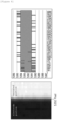
FIG. 8 is an image showing pixel coordinates of a second final boundary of the boundary detection device according to an experimental example of the present invention. -
FIG. 8 shows that the boundary error of the final boundary which is measured by the boundary detection device according to the experimental example of the present invention falls within 2 pixels, when the pixel coordinates where the actual boundary on the second electrode image is located is 5392 pixel. - The boundary detection device and method according to embodiments of the present invention have been described above.
- The boundary detection device and method according to embodiments of the present invention may acquire a first electrode image and a second electrode image with different brightness values in which the same electrode is captured and detect final boundaries of the uncoated portion from the second electrode image based on pixel coordinate information of boundaries of the uncoated portion obtained from the first electrode image, thereby improving detection accuracy of boundary detection.
- The operations of the method according to the embodiments of the present invention may be implemented as a computer-readable program or code on a computer-readable recording medium. The computer-readable recording medium includes all types of recording devices in which data readable by a computer system is stored. In addition, the computer-readable recording medium may be distributed in a network-connected computer system to store and execute computer-readable programs or codes in a distributed manner.
- In addition, the computer-readable recording medium may include hardware devices specially configured to store and execute program instructions, such as ROM, RAM, flash memory, etc. The program instructions may include not only machine language code created by a compiler, but also high-level language code that can be executed by a computer using an interpreter.
- Although some aspects of the invention have been described in the context of the apparatus, it may also represent a description according to a corresponding method, wherein a block or apparatus corresponds to a method step or feature of a method step. Similarly, aspects described in the context of a method may also represent a feature of a corresponding block or item or a corresponding apparatus. Some or all of the method steps may be performed by (or using) a hardware device, such as, for example, a microprocessor, a programmable computer, or an electronic circuit. In some embodiments, one or more of the most important method steps may be performed by such an apparatus.
- In the forgoing, the present invention has been described with reference to the exemplary embodiment of the present invention, but those skilled in the art may appreciate that the present invention may be variously corrected and changed within the range without departing from the spirit and the area of the present invention described in the appending claims.
Claims (17)
- A boundary detection device for detecting boundaries of an uncoated portion within battery electrodes, the boundary detection device comprising:at least one processor; anda memory configured to store at least one instruction executed by the at least one processor,wherein the at least one instruction includes:an instruction to obtain a first electrode image and a second electrode image in which the same electrode located at the same point is captured;an instruction to detect pixel information of temporary boundaries on both sides of an uncoated portion in the electrode from the first electrode image; andan instruction to detect final boundaries on both sides of the uncoated portion from the second electrode image based on the pixel information.
- The boundary detection device of claim 1, wherein the first electrode image is an image captured by adjusting an exposure value of a camera so that a pixel brightness value of the uncoated portion in the first electrode image is a predetermined first threshold value.
- The boundary detection device of claim 2, wherein the second electrode image is an image captured by adjusting an exposure value of a camera so that a pixel brightness value of the uncoated portion in the second electrode image is a second threshold value, wherein the second threshold value is different from the first threshold value.
- The boundary detection device of claim 1, wherein the instruction to detect the pixel information of the temporary boundaries on both sides of the uncoated portion includes:an instruction to detect the temporary boundaries on both sides of the uncoated portion in the first electrode image; andan instruction to obtain pixel coordinate information of the temporary boundaries.
- The boundary detection device of claim 4, wherein the instruction to detect the temporary boundaries includes:an instruction to detect a first temporary boundary located on one side of the uncoated portion in the first electrode image using a derivative mask filter; andan instruction to detect a second temporary boundary located on the other side of the uncoated portion in the first electrode image using the derivative mask filter.
- The boundary detection device of claim 5, wherein the derivative mask filter is a Sobel filter.
- The boundary detection device of claim 1, wherein the instruction to detect the final boundaries includes:an instruction to identify pixel coordinate information of a first temporary boundary and a second temporary boundary and obtain a first virtual boundary and a second virtual boundary which are located at the same points on the second electrode image where the first temporary boundary and the second temporary boundary are located; andan instruction to determine a first inspection area and a second inspection area based on the first virtual boundary and the second virtual boundary, respectively, and detect a first final boundary and a second final boundary from the first inspection area and the second inspection area, respectively.
- The boundary detection device of claim 7, wherein the instruction to detect the first final boundary and the second final boundary includes:an instruction to detect pixels having the maximum value in difference of brightness value compared to neighboring pixels within the first inspection area, as the first final boundary; andan instruction to detect pixels having the maximum value in difference of brightness value compared to neighboring pixels within the second inspection area, as the second final boundary.
- A boundary detection method for detecting boundaries of uncoated region within battery electrodes, the method comprising:acquiring a first electrode image and a second electrode image in which the same electrode located at the same point is captured;detecting pixel information of temporary boundaries on both sides of an uncoated portion in the electrode from the first electrode image; anddetecting final boundaries on both sides of the uncoated portion from the second electrode image based on the pixel information.
- The boundary detection method of claim 9, wherein the first electrode image is an image captured by adjusting an exposure value of a camera so that a pixel brightness value of the uncoated portion in the first electrode image is a predetermined first threshold value.
- The boundary detection method of claim 10, wherein the second electrode image is an image captured by adjusting an exposure value of a camera so that a pixel brightness value of the uncoated portion in the second electrode image is a second threshold value, wherein the second threshold value is different from the first threshold value.
- The boundary detection method of claim 9, wherein the detecting the pixel information of the temporary boundaries on both sides of the uncoated portion includes:detecting the temporary boundaries on both sides of the uncoated portion in the first electrode image; andobtaining pixel coordinate information of the temporary boundaries.
- The boundary detection method of claim 12, wherein the detecting the temporary boundaries includes:detecting a first temporary boundary located on one side of the uncoated portion in the first electrode image using a derivative mask filter; anddetecting a second temporary boundary located on the other side of the uncoated portion in the first electrode image using the derivative mask filter.
- The boundary detection method of claim 13, wherein the derivative mask filter is a Sobel filter.
- The boundary detection method of claim 9, wherein the detecting the final boundaries includes:identifying pixel coordinate information of a first temporary boundary and a second temporary boundary and obtaining a first virtual boundary and a second virtual boundary which are located at the same points on the second electrode image where the first temporary boundary and the second temporary boundary are located; anddetermining a first inspection area and a second inspection area based on the first virtual boundary and the second virtual boundary, respectively; and detecting a first final boundary and a second final boundary from the first inspection area and the second inspection area, respectively.
- The boundary detection method of claim 15, wherein the detecting the first final boundary and the second final boundary includes:detecting pixels having the maximum value in difference of brightness value compared to neighboring pixels within the first inspection area, as the first final boundary; anddetecting pixels having the maximum value in difference of brightness value (gray level) compared to neighboring pixels within the second inspection area, as the second final boundary.
- A boundary detection system for detecting boundaries of an uncoated portion within battery electrodes, the boundary detection system comprising:an imaging device configured to generate a first electrode image and a second electrode image in which the same electrode located at the same point is captured with different brightness values, by adjusting an exposure value; anda boundary detection device configured to obtain the first electrode image and the second electrode image from the imaging device, to detect pixel information of temporary boundaries on both sides of an uncoated portion in the electrode from the first electrode image, and to detect final boundaries on both sides of the uncoated portion from the second electrode image based on the pixel information.
Applications Claiming Priority (3)
| Application Number | Priority Date | Filing Date | Title |
|---|---|---|---|
| KR20220109764 | 2022-08-31 | ||
| KR1020230103920A KR20240031047A (en) | 2022-08-31 | 2023-08-09 | Apparatus and method for detecting edge of battery electrode |
| PCT/KR2023/012877 WO2024049196A1 (en) | 2022-08-31 | 2023-08-30 | Boundary line detection device and method |
Publications (2)
| Publication Number | Publication Date |
|---|---|
| EP4582768A1 true EP4582768A1 (en) | 2025-07-09 |
| EP4582768A4 EP4582768A4 (en) | 2025-12-31 |
Family
ID=90098278
Family Applications (1)
| Application Number | Title | Priority Date | Filing Date |
|---|---|---|---|
| EP23860872.3A Pending EP4582768A4 (en) | 2022-08-31 | 2023-08-30 | DEVICE AND METHOD FOR DETECTING BOUNDARIES |
Country Status (7)
| Country | Link |
|---|---|
| US (1) | US20250278840A1 (en) |
| EP (1) | EP4582768A4 (en) |
| JP (1) | JP2025516274A (en) |
| CN (1) | CN119183519A (en) |
| CA (1) | CA3248554A1 (en) |
| MX (1) | MX2024013562A (en) |
| WO (1) | WO2024049196A1 (en) |
Family Cites Families (11)
| Publication number | Priority date | Publication date | Assignee | Title |
|---|---|---|---|---|
| JPH0642933A (en) * | 1992-07-23 | 1994-02-18 | Taiyo Yuden Co Ltd | Apparatus for inspecting appearance of electronic part |
| KR0141308B1 (en) * | 1994-07-29 | 1998-06-15 | 배순훈 | Method for detection the contour and device thereof |
| JPH08101133A (en) * | 1994-09-30 | 1996-04-16 | Suzuki Motor Corp | Cylindrical joint detection device |
| JP2010025799A (en) * | 2008-07-22 | 2010-02-04 | Toyota Motor Corp | Apparatus for detecting boundary of covering film |
| KR20140136138A (en) * | 2013-05-20 | 2014-11-28 | 삼성전자주식회사 | Apparatas and method fof conducting a weighted bluring in a electronic device |
| KR102458433B1 (en) * | 2020-09-11 | 2022-10-26 | 주토스 주식회사 | Secondary battery polar-plate coating pattern length measurement device |
| KR20220048191A (en) * | 2020-10-12 | 2022-04-19 | 주식회사 엘지화학 | Method for analyzing shape properties of positive electrode active material |
| CN112525917A (en) * | 2020-11-12 | 2021-03-19 | 欣旺达电动汽车电池有限公司 | Battery cell tab detection method, device and system and storage medium |
| KR102953920B1 (en) * | 2020-12-17 | 2026-04-16 | 주식회사 엘지에너지솔루션 | System for inspecting battery cell and method for inspecting battery cell |
| KR102581000B1 (en) | 2021-01-29 | 2023-09-21 | 네이버 주식회사 | Method and ststem for providing assistant service |
| KR102822459B1 (en) | 2021-12-29 | 2025-06-23 | 세메스 주식회사 | Teaching method of transfer equipment and Teaching processing system of transfer equipment |
-
2023
- 2023-08-30 CA CA3248554A patent/CA3248554A1/en active Pending
- 2023-08-30 JP JP2024564599A patent/JP2025516274A/en active Pending
- 2023-08-30 CN CN202380038390.9A patent/CN119183519A/en active Pending
- 2023-08-30 WO PCT/KR2023/012877 patent/WO2024049196A1/en not_active Ceased
- 2023-08-30 EP EP23860872.3A patent/EP4582768A4/en active Pending
- 2023-08-30 US US18/862,307 patent/US20250278840A1/en active Pending
-
2024
- 2024-11-01 MX MX2024013562A patent/MX2024013562A/en unknown
Also Published As
| Publication number | Publication date |
|---|---|
| MX2024013562A (en) | 2024-12-06 |
| WO2024049196A1 (en) | 2024-03-07 |
| EP4582768A4 (en) | 2025-12-31 |
| US20250278840A1 (en) | 2025-09-04 |
| JP2025516274A (en) | 2025-05-27 |
| CA3248554A1 (en) | 2025-07-10 |
| CN119183519A (en) | 2024-12-24 |
Similar Documents
| Publication | Publication Date | Title |
|---|---|---|
| DE102016120026B4 (en) | Measuring device and method, program, product manufacturing method, calibration marking element, processing device and processing system | |
| US12607575B2 (en) | Method for determining the placement accuracy of a plurality of electrode sheets in a stack | |
| US11333658B2 (en) | Urine test strip comprising timer, and method for detecting and analyzing urine test strip | |
| DE102016013986B4 (en) | DEVICE FOR MEASURING THE POSITIONS AND POSITIONS OF A MULTIPLE OF ARTICLES AND THE DEVICE PROVIDING ROBOT SYSTEM | |
| KR20240031047A (en) | Apparatus and method for detecting edge of battery electrode | |
| CN112558043B (en) | Laser radar calibration method and electronic equipment | |
| US12243271B2 (en) | Calibration board and calibration method and system | |
| EP3534334B1 (en) | Method for identification of characteristic points of a calibration pattern within a set of candidate points derived from an image of the calibration pattern | |
| US20190163991A1 (en) | Method and apparatus for detecting road lane | |
| US10719938B2 (en) | Method and apparatus for recognizing edges in a camera image, and vehicle | |
| CN116046817B (en) | Tire quality testing methods, devices, electronic equipment and readable storage media | |
| CN117422777A (en) | Security check machine calibration method, related method, device, equipment and storage medium | |
| US20250278840A1 (en) | Boundry Line Detection Device and Method | |
| CN114219806A (en) | Automobile radar detection method, device, equipment, medium and product | |
| JP2900425B2 (en) | Image quality inspection equipment | |
| CA3254732A1 (en) | Device and method for inspecting battery electrode | |
| CN116543056A (en) | Linear camera calibration and calibration method, device and storage medium | |
| CN118424162B (en) | A laser rangefinder polygon area measurement method, device and storage medium | |
| US6985609B2 (en) | Method for identifying an object image | |
| CN112651261A (en) | Calculation method for conversion relation between high-precision 2D camera coordinate system and mechanical coordinate system | |
| CN116193240B (en) | Electronic equipment state evaluation method and system | |
| JP5841403B2 (en) | Color density measuring apparatus, color density measuring method, and color density measuring program | |
| CN116912967A (en) | Detection method, detection device and snap box quality inspection system for snap box quality | |
| CN115829867A (en) | Wide-angle image distortion and chromatic aberration processing method, device and medium based on calibration | |
| CN114494330B (en) | Positioning method, device, computer equipment and storage medium |
Legal Events
| Date | Code | Title | Description |
|---|---|---|---|
| STAA | Information on the status of an ep patent application or granted ep patent |
Free format text: STATUS: THE INTERNATIONAL PUBLICATION HAS BEEN MADE |
|
| PUAI | Public reference made under article 153(3) epc to a published international application that has entered the european phase |
Free format text: ORIGINAL CODE: 0009012 |
|
| STAA | Information on the status of an ep patent application or granted ep patent |
Free format text: STATUS: REQUEST FOR EXAMINATION WAS MADE |
|
| 17P | Request for examination filed |
Effective date: 20241008 |
|
| AK | Designated contracting states |
Kind code of ref document: A1 Designated state(s): AL AT BE BG CH CY CZ DE DK EE ES FI FR GB GR HR HU IE IS IT LI LT LU LV MC ME MK MT NL NO PL PT RO RS SE SI SK SM TR |
|
| DAV | Request for validation of the european patent (deleted) | ||
| DAX | Request for extension of the european patent (deleted) | ||
| A4 | Supplementary search report drawn up and despatched |
Effective date: 20251202 |
|
| RIC1 | Information provided on ipc code assigned before grant |
Ipc: G01B 11/02 20060101AFI20251126BHEP Ipc: G01B 11/03 20060101ALI20251126BHEP Ipc: G01N 21/84 20060101ALI20251126BHEP Ipc: G06T 7/00 20170101ALI20251126BHEP Ipc: G06T 7/11 20170101ALI20251126BHEP Ipc: G06T 7/13 20170101ALI20251126BHEP Ipc: H01M 10/04 20060101ALI20251126BHEP Ipc: G06T 7/12 20170101ALI20251126BHEP Ipc: G06T 7/136 20170101ALI20251126BHEP |