EP4582746A1 - Air conditioner - Google Patents
Air conditioner Download PDFInfo
- Publication number
- EP4582746A1 EP4582746A1 EP22957121.1A EP22957121A EP4582746A1 EP 4582746 A1 EP4582746 A1 EP 4582746A1 EP 22957121 A EP22957121 A EP 22957121A EP 4582746 A1 EP4582746 A1 EP 4582746A1
- Authority
- EP
- European Patent Office
- Prior art keywords
- air conditioner
- support member
- pulse unit
- indoor
- heat exchanger
- Prior art date
- Legal status (The legal status is an assumption and is not a legal conclusion. Google has not performed a legal analysis and makes no representation as to the accuracy of the status listed.)
- Pending
Links
Images



Classifications
-
- F—MECHANICAL ENGINEERING; LIGHTING; HEATING; WEAPONS; BLASTING
- F24—HEATING; RANGES; VENTILATING
- F24F—AIR-CONDITIONING; AIR-HUMIDIFICATION; VENTILATION; USE OF AIR CURRENTS FOR SCREENING
- F24F1/00—Room units for air-conditioning, e.g. separate or self-contained units or units receiving primary air from a central station
- F24F1/0007—Indoor units, e.g. fan coil units
- F24F1/0071—Indoor units, e.g. fan coil units with means for purifying supplied air
- F24F1/0076—Indoor units, e.g. fan coil units with means for purifying supplied air by electric means, e.g. ionisers or electrostatic separators
-
- A—HUMAN NECESSITIES
- A61—MEDICAL OR VETERINARY SCIENCE; HYGIENE
- A61L—METHODS OR APPARATUS FOR STERILISING MATERIALS OR OBJECTS IN GENERAL; DISINFECTION, STERILISATION OR DEODORISATION OF AIR; CHEMICAL ASPECTS OF BANDAGES, DRESSINGS, ABSORBENT PADS OR SURGICAL ARTICLES; MATERIALS FOR BANDAGES, DRESSINGS, ABSORBENT PADS OR SURGICAL ARTICLES
- A61L9/00—Disinfection, sterilisation or deodorisation of air
- A61L9/16—Disinfection, sterilisation or deodorisation of air using physical phenomena
- A61L9/18—Radiation
- A61L9/20—Ultraviolet radiation
-
- F—MECHANICAL ENGINEERING; LIGHTING; HEATING; WEAPONS; BLASTING
- F24—HEATING; RANGES; VENTILATING
- F24F—AIR-CONDITIONING; AIR-HUMIDIFICATION; VENTILATION; USE OF AIR CURRENTS FOR SCREENING
- F24F1/00—Room units for air-conditioning, e.g. separate or self-contained units or units receiving primary air from a central station
- F24F1/0007—Indoor units, e.g. fan coil units
- F24F1/0059—Indoor units, e.g. fan coil units characterised by heat exchangers
- F24F1/0063—Indoor units, e.g. fan coil units characterised by heat exchangers by the mounting or arrangement of the heat exchangers
-
- F—MECHANICAL ENGINEERING; LIGHTING; HEATING; WEAPONS; BLASTING
- F24—HEATING; RANGES; VENTILATING
- F24F—AIR-CONDITIONING; AIR-HUMIDIFICATION; VENTILATION; USE OF AIR CURRENTS FOR SCREENING
- F24F1/00—Room units for air-conditioning, e.g. separate or self-contained units or units receiving primary air from a central station
- F24F1/0007—Indoor units, e.g. fan coil units
- F24F1/0071—Indoor units, e.g. fan coil units with means for purifying supplied air
-
- F—MECHANICAL ENGINEERING; LIGHTING; HEATING; WEAPONS; BLASTING
- F24—HEATING; RANGES; VENTILATING
- F24F—AIR-CONDITIONING; AIR-HUMIDIFICATION; VENTILATION; USE OF AIR CURRENTS FOR SCREENING
- F24F13/00—Details common to, or for air-conditioning, air-humidification, ventilation or use of air currents for screening
- F24F13/20—Casings or covers
-
- F—MECHANICAL ENGINEERING; LIGHTING; HEATING; WEAPONS; BLASTING
- F24—HEATING; RANGES; VENTILATING
- F24F—AIR-CONDITIONING; AIR-HUMIDIFICATION; VENTILATION; USE OF AIR CURRENTS FOR SCREENING
- F24F8/00—Treatment, e.g. purification, of air supplied to human living or working spaces otherwise than by heating, cooling, humidifying or drying
- F24F8/20—Treatment, e.g. purification, of air supplied to human living or working spaces otherwise than by heating, cooling, humidifying or drying by sterilisation
- F24F8/22—Treatment, e.g. purification, of air supplied to human living or working spaces otherwise than by heating, cooling, humidifying or drying by sterilisation using UV light
-
- A—HUMAN NECESSITIES
- A61—MEDICAL OR VETERINARY SCIENCE; HYGIENE
- A61L—METHODS OR APPARATUS FOR STERILISING MATERIALS OR OBJECTS IN GENERAL; DISINFECTION, STERILISATION OR DEODORISATION OF AIR; CHEMICAL ASPECTS OF BANDAGES, DRESSINGS, ABSORBENT PADS OR SURGICAL ARTICLES; MATERIALS FOR BANDAGES, DRESSINGS, ABSORBENT PADS OR SURGICAL ARTICLES
- A61L2209/00—Aspects relating to disinfection, sterilisation or deodorisation of air
- A61L2209/10—Apparatus features
- A61L2209/14—Filtering means
-
- A—HUMAN NECESSITIES
- A61—MEDICAL OR VETERINARY SCIENCE; HYGIENE
- A61L—METHODS OR APPARATUS FOR STERILISING MATERIALS OR OBJECTS IN GENERAL; DISINFECTION, STERILISATION OR DEODORISATION OF AIR; CHEMICAL ASPECTS OF BANDAGES, DRESSINGS, ABSORBENT PADS OR SURGICAL ARTICLES; MATERIALS FOR BANDAGES, DRESSINGS, ABSORBENT PADS OR SURGICAL ARTICLES
- A61L2209/00—Aspects relating to disinfection, sterilisation or deodorisation of air
- A61L2209/10—Apparatus features
- A61L2209/16—Connections to a HVAC unit
Definitions
- air conditioners mostly use ultraviolet lamp devices for sterilization, but the penetrability of ultraviolet light is not strong, and it is impossible to achieve comprehensive and effective sterilization of the air conditioner.
- the present disclosure aims to solve at least one of the technical problems in the related art to some extent.
- the present disclosure provides an air conditioner.
- the air conditioner performs sterilization treatment on air entering an indoor air duct, in such a manner that indoor air maintains ultra-high cleanliness, which meets a user's demand for clean air, and enhances use experience.
- the sterilization module performs sterilization treatment on the airflow entering the indoor air duct, in such a manner that indoor air maintains the ultra-high cleanliness, which meets the user's demand for the clean air, and enhances the use experience.
- sterilization is achieved with low energy consumption.
- the air conditioner 100 comprises a casing 1, an indoor heat exchanger 2, an indoor fan 3, and a sterilization module 4.
- the casing 1 defines an indoor air duct 100a therein.
- the indoor air duct 100a has an indoor air inlet 100b and an indoor air outlet 100c.
- the indoor heat exchanger 2 and the indoor fan 3 are disposed in the indoor air duct 100a. Under a driving of the indoor fan 3, indoor air can flow through the indoor air inlet 100b to the indoor air duct 100a, exchange heat with the indoor heat exchanger 2, and finally flow into an indoor space through the indoor air outlet 100c, which realizes circulation of the indoor air and at least allows for an adjustment of an indoor temperature.
- the sterilization module 4 is disposed in the casing 1 and can be directly or indirectly connected to the casing 1.
- the sterilization module 4 is configured to at least sterilize an airflow in the indoor air duct 100a (e.g., cold air or hot air in the indoor air duct 1a) to improve a quality of the indoor air.
- the sterilization module 4 comprises a pulse unit 41 configured to output pulsed intense light to at least sterilize the airflow in the indoor air duct 100a.
- the pulsed intense light is used to irradiate the airflow in the indoor air duct 100a to achieve highly efficient sterilization of the indoor air duct 100a.
- the pulsed intense light can remove gaseous pollutants (such as formaldehyde, toluene, or acetic acid) in the indoor air duct 100a, in such a manner that the indoor air maintains ultra- high cleanliness, which effectively improves the quality of the indoor air, meets a user's demand for clean air, and enhances use experience.
- the pulsed intense light outputted by the pulse unit 41 great damages are caused to microorganisms such as bacteria, which reduces internal enzyme activity or even destroy DNA and RNA structures of the microorganisms, leading to death of the microorganisms such as bacteria.
- white intense light is outputted by the pulse unit 41 in a form of pulses to at least irradiate air in the indoor air duct 100a, for killing the bacteria.
- there is no need to heat the air which reduces energy consumption of the sterilization module 4 and therefore lowers cost of use for the user.
- the pulsed intense light comprises multi-spectrum light, comprising ultraviolet light, infrared light, and visible light.
- the ultraviolet light has an important role in sterilization, while the infrared light provides synergistic sterilization, in such a manner that the sterilization module 4 has a satisfactory sterilization effect and a satisfactory sterilization efficiency, which facilitates ensuring a sterilization ability of the sterilization module 4, and further reduces the energy consumption of the sterilization module 4.
- the ultraviolet light in the pulsed intense light can destroy genetic materials of the microorganisms such as bacteria, leading to death of the bacteria.
- the infrared light in the pulsed intense light can rapidly increase a temperature of the bacteria, leading to dehydration and death of the bacteria.
- the visible light in the pulsed intense light can destroy protein structures of the bacteria through a pulse flash effect, high penetrability, and high impact of the visible light, which causes protein denaturation and leads to death of the bacteria, offering a satisfactory sterilization efficiency and satisfactory compatibility.
- the pulsed intense light outputted by the sterilization module 4 can at least realize safe (mercury-free), effective, and energy-efficient cold sterilization (i.e., non-heating sterilization) for the airflow in the indoor air duct 100a.
- safe sterilization-free
- energy-efficient cold sterilization i.e., non-heating sterilization
- the sterilization for the airflow there is no need to heat the airflow, which is conducive to reducing the energy consumption of the sterilization, and also has a substantially minimal impact on a temperature and other characteristics of the airflow, thereby facilitating the air conditioner 100 to adjust the indoor temperature or the like.
- a substantially negligible effect of the sterilization module 4 on the temperature of the airflow facilitates maintenance of a cooling efficiency of the air conditioner 100 and reduces the energy consumption of the air conditioner 100 associated with cooling.
- the sterilization module 4 produces small environmental pollution when in operation, which facilitates provision of a friendly use environment for the user, and poses no harm to humans, helping to ensure health of the user.
- the pulse unit 41 outputs the pulsed intense light to realize the sterilization. Due to the high penetrability of the pulsed intense light, the sterilization efficiency and the sterilization effect for the indoor air duct 100a can be improved to realize highly efficient sterilization of the indoor air duct 100a, making the indoor air cleaner, and improving the quality of the indoor air. Compared with the ultraviolet ray sterilization technology in the related art, the sterilization module 4 in the present disclosure can sterilize a wider variety of microorganisms, saving sterilization time, and realizing low energy consumption of the sterilization module 4.
- the ultraviolet ray sterilization relies on a photochemical effect, which constitutes a main sterilization mechanism of the ultraviolet ray sterilization.
- the photochemical effect refers to an optical reaction produced when microorganisms receive light irradiation of a specific wavelength.
- pyrimidine and isomers of the pyrimidine are formed. These substances disrupt metabolic functions of the microorganisms and cause genetic abnormalities of the microorganisms, eventually leading to the death of the microorganisms.
- the pulsed intense light employs a photothermal sterilization mechanism.
- a photothermal effect refers to a temperature increase of a substance after the substance absorbs light energy.
- the microorganisms When exposed to the pulsed intense light at close range, the microorganisms rapidly absorb a large amount of light energy in a short period, and thus a surface temperature of the microorganisms increases rapidly, which results in complete destruction of a surface structure of the microorganisms, leading to death of the microorganisms. Since an entire photothermal process is extremely short, an object being irradiated does not experience a temperature increase. Therefore, the pulsed intense light, which employs the photothermal sterilization mechanism, can effectively kill all types of microorganisms.
- the table below reveals a comparison between pulsed intense light sterilization and ultraviolet light sterilization. Since the pulsed intense light encompasses an ultraviolet wavelength spectrum, the pulsed intense light also possesses a photochemical sterilization mechanism. However, in the pulsed intense light, the photochemical sterilization mechanism plays only a supplementary role. For microorganisms such as molds and spores, ultraviolet rays struggle to penetrate dense cell wall structures, and thus DNA cannot absorb the ultraviolet rays. Consequently, the ultraviolet ray sterilization is much less efficient than the pulsed intense light sterilization.
- the pulse unit 41 ionizes inert gases through a high-voltage power supply, exciting photons to produce instantaneous high-intensity light.
- the pulsed intense light comprises multi-spectrum light ranging from 100 nm to 1 mm.
- the pulse unit 41 comprises a xenon lamp 4121.
- the pulsed intense light is generated by applying a high voltage to the xenon lamp 4121, causing rapid ionization of a xenon gas inside the xenon lamp 4121 within an extremely short time period. In this way, the xenon gas releases the instantaneous high-intensity light produced through exciting the photons in a form of high-intensity light radiation.
- the pulse unit 41 is not limited in this regard.
- the indoor heat exchanger 2 comprises a heat exchanger body 21 and two support members 22.
- the two support members 22 are respectively disposed at two ends of the heat exchanger body 21 in a length direction of the heat exchanger body 21.
- At least one of the two support members 22 is provided with the sterilization module 4. In this way, stability of the sterilization module 4 at the air conditioner 100 can be improved, which therefore ensures operation stability of the sterilization module 4, and facilitates a centralized arrangement of the indoor heat exchanger 2 and the sterilization module 4.
- the sterilization module 4 is disposed in at least one of two ends of the indoor heat exchanger 2 in a length direction of the indoor heat exchanger 2, in such a manner that the indoor heat exchanger 2 and the sterilization module 4 have a compact structure, which is conducive to saving a space occupied by the indoor heat exchanger 2 and the sterilization module 4, improving a utilization rate of a space in the air conditioner 100.
- At least part of the pulse unit 41 is located at a side of a corresponding support member 22 of the two support members 22 facing towards the other support member 22 of the two support members 22.
- a part or all of the pulse unit 41 is located at the side of the corresponding support member 22 facing towards the other support member 22, which facilitates an arrangement of the pulse unit 41 in a space adjacent to the indoor heat exchanger 2, and is conducive to expanding irradiation coverage of the pulsed intense light outputted by the pulse unit 41 in the indoor air duct 100a. In this way, an effective sterilization region of the pulse unit 41 in the indoor air duct 100a is increased, ensuring a sterilization effect of the sterilization module 4.
- the above arrangement of the sterilization module 4 facilitates a reasonable adjustment of the sterilization module 4 to better adapt to the air conditioner 100, e.g., a reasonable adjustment of an increase in a length of the sterilization module 4, which facilitates ensuring that the sterilization module 4 has a suitable sterilization range, and is conducive to realizing effective sterilization in the indoor air duct 100a through mounting only one sterilization module 4. In this way, manufacturing costs of the air conditioner 100 are saved, which facilitates adaptation of the sterilization module 4 to differentiated needs for sterilization of different air conditioners 100.
- the length direction of the heat exchanger body 21 is a left-right direction.
- the support member 22 at a left side is provided with the sterilization module 4.
- the support member 22 at a right side is provided with no sterilization module 4.
- each of the support member 22 at the left side and the support member 22 at the right side may be provided with the sterilization module 4.
- the support member 22 at the left side is provided with no sterilization module 4, and the support member 22 at the right side is provided with the sterilization module 4.
- the pulse unit 41 is arranged in an extension direction of the indoor heat exchanger 2 and extends towards the other support member 22, in such a manner that a length direction of the pulse unit 41 is consistent with the length direction of the indoor heat exchanger 2, which is conducive to increasing an irradiation area of the pulse unit 41 on the airflow in the indoor air duct 100a, further improving the sterilization effect.
- a reduction of a space occupied by the pulse unit 41 in a plane perpendicular to the length direction of the indoor heat exchanger 2 is facilitated, which further facilitates the arrangement of the sterilization module 4 in the air-conditioner 100.
- the pulse unit 41 is not limited to being arranged in the above direction.
- the pulse unit 41 may be arranged in a direction perpendicular to the length direction of the indoor heat exchanger 2.
- a position of the abutment portion 41111 is not limited in this regard.
- the position of the abutment portion 41111 in the length direction of the pulse unit 41 can be set as desired.
- the position of the abutment portion 41111 in an axial direction of the mounting bracket 411 is adjusted to control a length of a part of the pulse unit 41 that extends out of the mounting hole 221 towards the other support member 22, and thus the irradiation area of the pulse unit 41 on the indoor air duct 100a is adjusted to adapt to a need for sterilization of the air conditioner 100.
- the fixing portion 41121 is located at the side of the corresponding support member 22 facing away from the other support member 22, and is fixed to the corresponding support member 22 by a fastener. With the first bracket 4111 and the second bracket 4112, mounting and fixation of the pulse unit 41 are facilitated.
- the first bracket 4111 comprises a protrusion and the second bracket 4112 comprises a snap.
- fixation between the first bracket 4111 and the second bracket 4112 is realized, which ensures overall structural stability of the first bracket 4111 and the second bracket 4112.
- a design of the protrusion and the snap facilitates a disassembly of the first bracket 4111 for replacement of the pulse light source 412, which eliminates a need to replace the entire sterilization module 4 due to damages to the pulse light source 412, saving later maintenance costs for the user.
- the mounting bracket 411 is integrally formed.
- the mounting bracket 411 has a mounting space 411a formed therein.
- the mounting space 411a has an emission opening 411b.
- the pulse light source 412 is disposed in the mounting space 411a.
- the pulse light source 412 is arranged in correspondence with the emission opening 411b, in such a manner that at least a large portion of the pulsed intense light outputted by the pulse light source 412 can be centrally emitted through the emission opening 411b to at least sterilize the airflow, which facilitates further improving the sterilization efficiency and the sterilization effect.
- the mounting bracket 411 can protect the pulse light source 412 from friction of other members, ensuring a normal operation of the pulse light source 412.
- the mounting bracket 411 and the pulse light source 412 both extend in the left-right direction.
- the emission opening 411b is formed at a bottom side of the mounting space 411a.
- the pulse light source 412 is located below the mounting bracket 411. At least part of the pulse light source 412 is disposed in the mounting space 411a.
- the emission opening 411b may be arranged towards the indoor air duct 100a and an internal member (e.g., the indoor fan 3), in such a manner that the sterilization module 4 can simultaneously sterilize the indoor air duct 100a and the internal member.
- Other members of the air conditioner 100 can also be sterilized by the sterilization module 4 when these members are within the irradiation coverage of the pulse light source 412.
- the pulse light source 412 comprises the xenon lamp 4121, a lampshade 4122, and a seal 4123.
- the xenon lamp 4121 is filled with inert gases comprising the xenon gas, which causes no pollution and is not hazardous to the human body.
- the lampshade 4122 is sleeved over the xenon lamp 4121 and has openings formed at two axial ends of the lampshade 4122, respectively, in such a manner that the xenon lamp 4121 is engaged in the lampshade 4122 through the openings.
- the seal 4123 is sealed at the opening.
- the lampshade 4122 is a glass member (e.g., a quartz member), a crystal member, etc., to ensure high light transmittance of the lampshade 4122, which facilitates ensuring the sterilization effect of the pulse light source 412.
- the seal 4123 is a silicone member or a rubber member, to facilitate provision of a soft connection while ensuring sealing performance of the mounting cavity.
- a part of the seal 4123 is sleeved over an end of the lampshade 4122 to provide protection for the lampshade 4122 by the seal 4123. In this way, the lampshade 4122 is prevented from coming into direct contact with other members to avoid cracks or the like in the lampshade 4122, which is conducive to improving operational safety and prolonging a service life of the pulse light source 412.
- the seal 4123 has an engagement groove at a side of the seal 4123 facing towards the lampshade 4122.
- the engagement groove is formed as a ring-shaped groove.
- the lampshade 4122 is inserted into and engaged with the engagement groove.
- An insulating sealant is disposed between a wall surface of the ring-shaped groove and the lampshade 4122 to provide sealing.
- the mounting bracket 411 further comprises the first bracket 4111.
- Each of the two seals 4123 is mounted at the first bracket 4111 to realize mounting of the xenon lamp 4121, which facilitates stable mounting of the pulse light source 412 as a whole and prevents a vibration generated by an operation of the air conditioner 100 from changing a position of the xenon lamp 4121, improving stability of the xenon lamp 4121.
- At least one of the two seals 4123 has a chamber in communication with the mounting cavity.
- the chamber has a through opening 4123a and a cable opening 4123b.
- a cable of the xenon lamp 4121 e.g., a positive cable, a negative cable, and a breakdown cable of the xenon lamp 4121
- the chamber can provide a predetermined route for an exit of the cable of the xenon lamp 4121.
- the seal 4123 and the first bracket 4111 can provide insulation protection for the cable of the xenon lamp 4121 to avoid safety hazards during use, and to avoid a need for a heat shrink tubing application of the cable of the xenon lamp 4121 in a small space, which facilitates improving mounting safety of the pulse light source 412.
- each of the two seals 4123 has the chamber.
- Each chamber has the cable opening 4123b.
- One terminal of the xenon lamp 4121 is a positive terminal
- another terminal of the xenon lamp 4121 is a negative terminal.
- Each of the positive terminal and the negative terminal is provided with the cable.
- the cable at the positive terminal can be inserted into the chamber of one of the two seals 4123 and extend out of the chamber through the cable opening 4123b of the one of the two seals 4123.
- the cable at the negative terminal can be inserted into the chamber of another one of the two seals 4123 and extend out of the chamber through the cable opening 4123b of the other one of the two seals 4123.
- the cable at the positive terminal and the cable at the negative terminal both extend into the chamber of a same seal 4123 and extend out of the chamber through the cable opening 4123b of the same seal 4123.
- the xenon lamp 4121 is further provided with the breakdown cable at the positive terminal or the negative terminal of the xenon lamp 4121.
- the breakdown cable may extend into the chamber of one of the two seals 4123 and extend out of the chamber through the cable opening 4123b of the one of the two seals 4123.
- the chamber is provided with the sealant to further ensure sealing performance of the mounting cavity, avoiding an intrusion of other foreign matters (e.g., water vapors) into the mounting cavity.
- the sealant such as silicone rubber is injected into the chamber through the through opening 4123a.
- the through opening 4123a may be formed at a side wall of the seal 4123 that extends in a circumferential direction of the xenon lamp 4121.
- the seal 4123 may be rotated to orient the through opening 4123a upwards, in such a manner that the sealant is prevented from flowing out during an injection of the sealant, which facilitates an operation and assurance of cleanliness of a workbench and the lampshade 4122.
- the insulating sealant is disposed at the through opening 4123a.
- the abutment portion 41111 extends into a ring-shaped structure in a circumferential direction of the mounting hole 221, and is sealingly engaged with an edge of the mounting hole 221.
- the abutment portion 41111 can be sealingly engaged with an entire circumferential edge of the mounting hole 221 to prevent the airflow in the indoor air duct 100a from flowing out through a gap between the mounting bracket 411 and the mounting hole 221, which avoids an air leakage of the air conditioner 100, facilitating assurance of an air discharge volume of the air conditioner 100.
- the foreign matters (such as dust) can be prevented from entering the indoor air duct 100a through the gap between the mounting bracket 411 and the mounting hole 221, which prevents a normal operation of the members in the air conditioner 100 from being affected.
- At least one of two opposite sides of the corresponding support member 22 in an axial direction of the mounting hole 221 has a limiting rib 222.
- the limiting rib 222 is arranged around the mounting hole 221 and engaged with an outer peripheral side of the pulse unit 41, to restrict a movement of the pulse unit 41 in a direction perpendicular to the length direction of the heat exchanger body 21 to a predetermined extent, ensuring that the mounting bracket 411 is stably engaged with the mounting hole 221.
- the limiting rib 222 defines a recess 223. A part of the pulse unit 41 located at the side of the corresponding support member 22 facing away from the other support member 22 is engaged with the recess 223.
- the recess 223 is used to confine the pulse unit 41 to provide a positional restriction and support, which is conducive to positioning and the mounting of the pulse unit 41.
- the sterilization module 4 further comprises a circuit unit 42.
- the circuit unit 42 comprises a box 421 and a circuit board 422.
- the box 421 is disposed at the side of the corresponding support member 22 (the corresponding support member 22 at which the sterilization module 4 is mounted) facing away from the other support member 22, and is fixed to the corresponding support member 22 by a fastener.
- the circuit board 422 is disposed in the box 421, and is electrically connected to the pulse unit 41, which facilitates provision of a suitable operation voltage for the pulse unit 41, and control over activation, deactivation, and an operational duration (e.g., the operational duration may range from two minutes to five minutes) of the pulse unit 41, conveniently adapting to a need of the user.
- the circuit unit 42 can be arranged without occupying a space between the two support members 22, freeing up more space for the mounting of the pulse unit 41.
- the pulse unit 41 and the circuit board 42 are located at two opposite sides of the support member 22, respectively. If the support member 22 has the mounting hole 221, the cable between the pulse unit 41 and the circuit board 42 may be routed through the mounting hole 221. If the support member 22 has no mounting hole 221, the cable between the pulse unit 41 and the circuit board 42 may be routed bypassing the support member 22, but is not limited to being routed in such a manner.
- the sterilization module 4 is constructed to perform sterilization once every 24 hours, and the duration of each sterilization is 2 min to 5 min.
- the indoor heat exchanger 2 comprises a heat exchanger body 21.
- the heat exchanger body 21 comprises a first heat exchange portion 211 and a second heat exchange portion 212.
- the first heat exchange portion 211 is angled relative to the second heat exchange portion 212.
- the box 421 has a square structure. A part of the box is accommodated in a space, corresponding to a space defined by the angle between the first heat exchange portion 211 and the second heat exchange portion 212, at the side of the corresponding support member 22 facing away from the other support member 22.
- a length direction of the square structure is arranged obliquely relative to a vertical direction.
- a width direction of the square structure is the same as an oblique direction of the second heat exchange portion 212. In this way, a sufficient mounting space can be provided for the box 421, and the box 421 does not interfere with a mounting portion of the indoor fan 3.
- the box 421 is filled with a sealant wrapping around the circuit board 422 to prevent water vapors and other foreign matters from causing short circuits, damages, or the like to the circuit board 422, which ensures a safe operation of the circuit board 422, and enhances reliability of electric control of the circuit unit 42.
- the sealant can wrap all of or a part of the circuit board 422.
- the sealant is a polyurethane adhesive.
- the circuit board 422 e.g., a PCB circuit board
- the sealant provides 100% coverage of all pins of the circuit board 422 to avoid damages to the circuit board 422.
- the box 421 comprises a first housing 4211 and a second housing 4212.
- the circuit board 422 is disposed in the first housing 4211.
- the second housing 4212 wraps around the first housing 4211. In this way, the second housing 4212 can provide protection for the first housing 4211 and the circuit board 422. With the first housing 4211 and the second housing 4212, dual-layer protection can be provided for the circuit board 422, ensuring safety of the circuit board 422.
- the first housing 4211 is a plastic member.
- the second housing 4212 is a sheet metal member.
- the first housing 4211 can provide satisfactory moisture and water resistance to effectively protect the circuit board 422 from being affected by condensed water at the support member 22 (e.g., condensed water generated by a support plate adjacent to the indoor heat exchanger 2 due to an operation of the indoor heat exchanger 2).
- the second housing 4212 has excellent fireproof and explosion-proof capabilities, thereby providing the circuit unit 42 with good waterproof and explosion-proof performance, further enhancing use safety of the circuit unit 42.
- the indoor heat exchanger 2 is used as an evaporator, if condensed water is generated at a surface of the box 421, a surface of the support member 22, etc., the condensed water will not flow into the box 421 through the second lead opening 421a since the second lead opening 421a is located at the lower side of the box 421, ensuring a normal operation of the circuit unit 42. Further, in view of a position of the second lead opening 421a, a part of the cable of the pulse unit 41 passes through the second lead opening 421a from bottom to up when the cable of the pulse unit 41 is connected to the circuit board 422 through the second lead opening 421a. In this way, even if condensed water presents at a surface of the cable, the condensed water will not flow along the cable towards the second lead opening 421a, which further enhances water resistance of the sterilization module 4.
- the sterilization module 4 is mounted at the support member 22 at the left side.
- a main electric control box of the air conditioner 100 is mounted at a right side of the indoor heat exchanger 2.
- a wire of the circuit board 422 may extend out of the second lead opening 421a, and is connected to a main electric control board of the air conditioner 100 under guidance of a plurality of wire clips at a base of the air conditioner 100, in such a manner such that the cable of the pulse unit 41 is electrically connected to the main electric control board by the circuit board 422.
- the pulse unit 41 further has a cable retention structure 413 at an end of the pulse unit 41 in the length direction of the pulse unit 41.
- the cable retention structure 413 is located between the first lead opening 41a and the second lead opening 421a.
- the cable of the pulse unit 41 passes through the cable retention structure 413. In this way, a centralized arrangement of a part of the cable located between the first lead opening 41a and the second lead opening 421a is facilitated, which restricts a movement of the cable to prevent the cable from affecting an operation of other members.
- a part of the cable of the pulse unit 41 is sandwiched between the box 421 and the corresponding support member 22. That is, the part of the cable of the pulse unit 41 located between the first lead opening 41a and the second lead opening 421a is sandwiched between the box 421 and the corresponding support member 22, which restricts the movement of the cable to prevent the cable from interfering with other members.
- the part of the cable of the pulse unit 41 located between the first lead opening 41a and the second lead opening 421a may also be arranged around an outer peripheral side of the box 421.
- the pulse unit 41 further has the cable retention structure 413 at the end of the pulse unit 41 in the length direction of the pulse unit 41.
- the cable retention structure 413 is located between the first lead opening 41a and the second lead opening 421a.
- the cable of the pulse unit 41 extends through the first lead opening 41a to the side of the corresponding support member 22 facing away from the other support member 22, passes through the cable retention structure 413, and then passes downwards through a space between the box 421 and the corresponding support member 22 to be sandwiched between the box 421 and the corresponding support member 22.
- the cable of the pulse unit 41 is arranged around a mounting post 4213 at the lower side of the box 421, and is connected to the circuit board 422 through the second lead opening 421a.
- the mounting post 4213 is fixed to the support member 22 by a fastener to realize mounting and fixation of the circuit unit 22.
- the sterilization module 4 is located between the indoor heat exchanger 2 and the indoor fan 3.
- the sterilization module 4 is configured to irradiate the indoor heat exchanger 2 and the indoor fan 3 to sterilize at least one of the indoor heat exchanger 2 and the indoor fan 3.
- the indoor heat exchanger 2 or the indoor fan 3 is sterilized by the pulse light source 412 to adapt to a need for the air conditioner 100 and ensure cleanliness of the indoor heat exchanger 2 or the indoor fan 3.
- the pulse unit 41 may irradiate a part or all of the indoor heat exchanger 2 to achieve sterilization. That is, when the pulse unit 41 is in operation, at least part of the indoor heat exchanger 2 is within the irradiation coverage of the pulsed intense light outputted by the pulse unit 41. Therefore, a relative position between the pulse light source 412 and the indoor heat exchanger 2 can be flexibly set to some extent.
- the pulse unit 41 may irradiate a part or all of the indoor fan 3 to achieve sterilization. That is, when the pulse unit 41 is in operation, at least part of the indoor fan 3 is within the irradiation coverage of the pulsed intense light outputted by the pulse unit 41.
- an irradiation direction of the pulsed intense light of the sterilization module 4 can be adapted to a mounting position of the sterilization module 4 to ensure a sterilization range of the pulsed intense light.
- the indoor heat exchanger 2 comprises the heat exchanger body 21.
- the heat exchanger body 21 comprises the first heat exchange portion 211 and the second heat exchange portion 212.
- the first heat exchange portion 211 is angled relative to the second heat exchange portion 212.
- An end of the first heat exchange portion 211 and an end of the second heat exchange portion 212 that are close to each other face towards an air intake side of the air conditioner 100.
- the sterilization module 4 is disposed between the first heat exchange portion 211 and the second heat exchange portion 212, and is located at an air intake side of the indoor fan 3.
- the sterilization module 4 is disposed at an upper side of the indoor fan 3 (e.g., the sterilization module 4 is located at a directly upper side or an obliquely upper side of the indoor fan 3).
- the pulsed intense light of the sterilization module 4 is arranged to irradiate the indoor air duct 100a obliquely relative to the vertical direction, but is not limited to being arranged in such a manner.
- a minimum spacing between the sterilization module 4 and the indoor heat exchanger 2 is x1, where x1 ⁇ 8 mm; and/or a minimum spacing between the sterilization module 4 and the indoor fan 3 is x2, where x2 ⁇ 15mm. Therefore, the sterilization module 4 is at a predetermined safety distance from other members while ensuring reliable mounting of the sterilization module 4, which avoids interference between the sterilization module 4 and other members (e.g., the indoor heat exchanger 2 and the indoor fan 3), preventing the normal operation of the sterilization module 4 and other members from being affected.
- the air conditioner 100 further comprises an electric auxiliary heating module 5.
- the electric auxiliary heating module 5 is located between the indoor heat exchanger 2 and the indoor fan 3. Two ends of the electric auxiliary heating module 5 in a length direction of the electric auxiliary heating module 5 are fixedly connected to the two support members 22 of the indoor heat exchanger 2, respectively, which facilitates mounting of the electric auxiliary heating module 5 to improve stability of the electric auxiliary heating module 5, and is conducive to increasing a heat exchange area between the electric auxiliary heating module 5 and the airflow in the indoor air duct 100a.
- the sterilization module 4 is disposed at a lower side of the electric auxiliary heating module 5 (e.g., the sterilization module 4 is located at a directly lower side or an obliquely lower side of the electric auxiliary heating module 5).
- the pulsed intense light of the sterilization module 4 irradiates downwards at the indoor air duct 100a.
- the sterilization module 4 may also be disposed at an upper side of the electric auxiliary heating module 5 (e.g., the sterilization module 4 is located at a directly upper side or an obliquely upper side of the electric auxiliary heating module 5), but is not limited to being disposed in such a manner.
- the sterilization module 4 is located at the obliquely lower side of the electric auxiliary heating module 5, in such a manner that the sterilization module 4 and the electric auxiliary heating module 5 may be offset from each other in the front-rear direction.
- the emission opening 411b of the sterilization module 4 is arranged obliquely downwards, which is convenient for enabling the irradiation coverage of the sterilization module 4 to be located below the electric auxiliary heating module 5, helping to maximize the irradiation coverage of the pulse unit 41.
- an outer contour of the sterilization module 4 can be better adapted to an arrangement space at the lower side of the electric auxiliary heating module 5, which is conducive to keeping the sterilization module 4 at a safe distance from other members such as the indoor heat exchanger 2 and the indoor fan 3.
- the length direction of the electric auxiliary heating module 5 is the same as the length direction of the pulse unit 41.
- Such an arrangement facilitating both a heating area of the electric auxiliary heating module 5 on the airflow in the indoor air duct 100a and an irradiation area of the pulse unit 41 on the airflow in the indoor air duct 100a, which is conducive to taking into account both the electric auxiliary heating effect of the electric auxiliary heating module 5 and the sterilization effect of the sterilization module 4, and helps to reduce a space occupied by the sterilization module 4 in the plane perpendicular to the length direction of the electric auxiliary heating module 5, further facilitating the arrangement of the sterilization module 4 in the air conditioner 100.
- a center axis of the electric auxiliary heating module 101 in the length direction of the electric auxiliary heating module 101 is parallel to and spaced apart from a center axis of the sterilization module 3 in a length direction of the sterilization module 3.
- the casing 1 has a display panel.
- the display panel is configured to display at least one of parameter information, mode information, and the like related to the air conditioner 100.
- the display panel may display information related to temperature (e.g., a set temperature of the air conditioner 100), air sensation, humidity, purification, fresh air, and sterilization.
- surrounding members e.g., the support member 22 or the electric auxiliary heating module 5
- surrounding members e.g., the support member 22 or the electric auxiliary heating module 5
- the sterilization module 4 is mounted at a periphery of the electric auxiliary heating module 5.
- the cable of the pulse unit 41 is a heat-resistant and anti-aging cable to ensure a service life of the air conditioner 100. If cables of other members are also in the irradiation coverage of the pulsed intense light, the cables of other members may also be heat-resistant and anti-aging cables.
Landscapes
- Engineering & Computer Science (AREA)
- Chemical & Material Sciences (AREA)
- Combustion & Propulsion (AREA)
- Mechanical Engineering (AREA)
- General Engineering & Computer Science (AREA)
- Health & Medical Sciences (AREA)
- Epidemiology (AREA)
- Life Sciences & Earth Sciences (AREA)
- Animal Behavior & Ethology (AREA)
- General Health & Medical Sciences (AREA)
- Public Health (AREA)
- Veterinary Medicine (AREA)
- Physics & Mathematics (AREA)
- Thermal Sciences (AREA)
- Air Filters, Heat-Exchange Apparatuses, And Housings Of Air-Conditioning Units (AREA)
Abstract
Description
- The present application claims priorities to
Chinese patent applications Nos. 202211056723.4 202222314458.7, both titled "AIR CONDITIONER" and filed by GD MIDEA AIR-CONDITIONING EQUIPMENT CO., LTD. on August 31, 2022 - The present disclosure relates to the field of air conditioner technologies, and more particularly, to an air conditioner.
- In the related art, air conditioners mostly use ultraviolet lamp devices for sterilization, but the penetrability of ultraviolet light is not strong, and it is impossible to achieve comprehensive and effective sterilization of the air conditioner.
- The present disclosure aims to solve at least one of the technical problems in the related art to some extent.
- To this end, the present disclosure provides an air conditioner. The air conditioner performs sterilization treatment on air entering an indoor air duct, in such a manner that indoor air maintains ultra-high cleanliness, which meets a user's demand for clean air, and enhances use experience.
- According to an embodiment of the present disclosure, an air conditioner comprises: a casing defining an indoor air duct therein; an indoor heat exchanger disposed in the indoor air duct; an indoor fan disposed in the indoor air duct; and a sterilization module disposed in the casing, the sterilization module comprising a pulse unit configured to output pulsed intense light to at least sterilize an airflow in the indoor air duct.
- With the air conditioner according to the embodiment of the present disclosure, the sterilization module performs sterilization treatment on the airflow entering the indoor air duct, in such a manner that indoor air maintains the ultra-high cleanliness, which meets the user's demand for the clean air, and enhances the use experience. In addition, sterilization is achieved with low energy consumption.
-
-
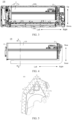
FIG. 1 is a schematic view of an air conditioner according to an embodiment of the present disclosure. -
FIG. 2 is a sectional view taken along line A-A inFIG. 1 . -
FIG. 3 is another schematic view of the air conditioner illustrated inFIG. 1 . -
FIG. 4 is yet another schematic view of the air conditioner illustrated inFIG. 1 . -
FIG. 5 is a sectional view taken along line B-B inFIG. 4 . -
FIG. 6 is another schematic view of the air conditioner illustrated inFIG. 4 . -
FIG. 7 is yet another schematic view of the air conditioner illustrated inFIG. 4 . -
FIG. 8 is a sectional view taken along line C-C inFIG. 5 . -
FIG. 9 is a schematic view of a pulse unit illustrated inFIG. 1 . -
FIG. 10 is a main view of the pulse unit illustrated inFIG. 9 . -
FIG. 11 is a side view of the pulse unit illustrated inFIG. 9 . -
FIG. 12 is a top view of the pulse unit illustrated inFIG. 9 . -
FIG. 13 is a sectional view taken along line D-D inFIG. 12 . -
FIG. 14 is a schematic view of a pulse light source illustrated inFIG. 9 . -
FIG. 15 is a schematic view of a circuit unit illustrated inFIG. 1 . -
FIG. 16 is a sectional view taken along line E-E inFIG. 15 . -
FIG. 17 is a side view of the circuit unit illustrated inFIG. 15 . -
FIG. 18 is another side view of the circuit unit illustrated inFIG. 15 . - Embodiments of the present disclosure will be described in detail below with reference to examples thereof as illustrated in the accompanying drawings, throughout which same or similar elements, or elements having same or similar functions, are denoted by same or similar reference numerals. The embodiments described below with reference to the drawings are illustrative only, and are intended to explain, rather than limit, the present disclosure.
- An
air conditioner 100 according to the embodiments of the present disclosure is described below with reference toFIG. 1 to FIG. 18 . - As illustrated in
FIG. 1 to FIG. 3 , theair conditioner 100 comprises a casing 1, an indoor heat exchanger 2, anindoor fan 3, and asterilization module 4. The casing 1 defines anindoor air duct 100a therein. Theindoor air duct 100a has anindoor air inlet 100b and anindoor air outlet 100c. The indoor heat exchanger 2 and theindoor fan 3 are disposed in theindoor air duct 100a. Under a driving of theindoor fan 3, indoor air can flow through theindoor air inlet 100b to theindoor air duct 100a, exchange heat with the indoor heat exchanger 2, and finally flow into an indoor space through theindoor air outlet 100c, which realizes circulation of the indoor air and at least allows for an adjustment of an indoor temperature. - The
sterilization module 4 is disposed in the casing 1 and can be directly or indirectly connected to the casing 1. Thesterilization module 4 is configured to at least sterilize an airflow in theindoor air duct 100a (e.g., cold air or hot air in the indoor air duct 1a) to improve a quality of the indoor air. - Therefore, the
air conditioner 100 has a sterilization function to ensure the quality of the air flowing into the indoor space, enriching functionality of theair conditioner 100. - The
sterilization module 4 comprises apulse unit 41 configured to output pulsed intense light to at least sterilize the airflow in theindoor air duct 100a. The pulsed intense light is used to irradiate the airflow in theindoor air duct 100a to achieve highly efficient sterilization of theindoor air duct 100a. The pulsed intense light can remove gaseous pollutants (such as formaldehyde, toluene, or acetic acid) in theindoor air duct 100a, in such a manner that the indoor air maintains ultra- high cleanliness, which effectively improves the quality of the indoor air, meets a user's demand for clean air, and enhances use experience. - Therefore, with the pulsed intense light outputted by the
pulse unit 41, great damages are caused to microorganisms such as bacteria, which reduces internal enzyme activity or even destroy DNA and RNA structures of the microorganisms, leading to death of the microorganisms such as bacteria. In addition, white intense light is outputted by thepulse unit 41 in a form of pulses to at least irradiate air in theindoor air duct 100a, for killing the bacteria. In addition, during sterilization process, there is no need to heat the air, which reduces energy consumption of thesterilization module 4 and therefore lowers cost of use for the user. - The pulsed intense light comprises multi-spectrum light, comprising ultraviolet light, infrared light, and visible light. The ultraviolet light has an important role in sterilization, while the infrared light provides synergistic sterilization, in such a manner that the
sterilization module 4 has a satisfactory sterilization effect and a satisfactory sterilization efficiency, which facilitates ensuring a sterilization ability of thesterilization module 4, and further reduces the energy consumption of thesterilization module 4. The ultraviolet light in the pulsed intense light can destroy genetic materials of the microorganisms such as bacteria, leading to death of the bacteria. The infrared light in the pulsed intense light can rapidly increase a temperature of the bacteria, leading to dehydration and death of the bacteria. The visible light in the pulsed intense light can destroy protein structures of the bacteria through a pulse flash effect, high penetrability, and high impact of the visible light, which causes protein denaturation and leads to death of the bacteria, offering a satisfactory sterilization efficiency and satisfactory compatibility. - Therefore, the pulsed intense light outputted by the
sterilization module 4 can at least realize safe (mercury-free), effective, and energy-efficient cold sterilization (i.e., non-heating sterilization) for the airflow in theindoor air duct 100a. During the sterilization for the airflow, there is no need to heat the airflow, which is conducive to reducing the energy consumption of the sterilization, and also has a substantially minimal impact on a temperature and other characteristics of the airflow, thereby facilitating theair conditioner 100 to adjust the indoor temperature or the like. In addition, when theair conditioner 100 is used for cooling, a substantially negligible effect of thesterilization module 4 on the temperature of the airflow facilitates maintenance of a cooling efficiency of theair conditioner 100 and reduces the energy consumption of theair conditioner 100 associated with cooling. In addition, thesterilization module 4 produces small environmental pollution when in operation, which facilitates provision of a friendly use environment for the user, and poses no harm to humans, helping to ensure health of the user. - With the
air conditioner 100 according to the embodiments of the present disclosure, thepulse unit 41 outputs the pulsed intense light to realize the sterilization. Due to the high penetrability of the pulsed intense light, the sterilization efficiency and the sterilization effect for theindoor air duct 100a can be improved to realize highly efficient sterilization of theindoor air duct 100a, making the indoor air cleaner, and improving the quality of the indoor air. Compared with the ultraviolet ray sterilization technology in the related art, thesterilization module 4 in the present disclosure can sterilize a wider variety of microorganisms, saving sterilization time, and realizing low energy consumption of thesterilization module 4. - In the related art, the ultraviolet ray sterilization relies on a photochemical effect, which constitutes a main sterilization mechanism of the ultraviolet ray sterilization. The photochemical effect refers to an optical reaction produced when microorganisms receive light irradiation of a specific wavelength. When double-stranded genetic information in the microorganisms such as bacteria is irradiated with ultraviolet light, pyrimidine and isomers of the pyrimidine are formed. These substances disrupt metabolic functions of the microorganisms and cause genetic abnormalities of the microorganisms, eventually leading to the death of the microorganisms.
- The pulsed intense light employs a photothermal sterilization mechanism. A photothermal effect refers to a temperature increase of a substance after the substance absorbs light energy. When exposed to the pulsed intense light at close range, the microorganisms rapidly absorb a large amount of light energy in a short period, and thus a surface temperature of the microorganisms increases rapidly, which results in complete destruction of a surface structure of the microorganisms, leading to death of the microorganisms. Since an entire photothermal process is extremely short, an object being irradiated does not experience a temperature increase. Therefore, the pulsed intense light, which employs the photothermal sterilization mechanism, can effectively kill all types of microorganisms.
- The table below reveals a comparison between pulsed intense light sterilization and ultraviolet light sterilization. Since the pulsed intense light encompasses an ultraviolet wavelength spectrum, the pulsed intense light also possesses a photochemical sterilization mechanism. However, in the pulsed intense light, the photochemical sterilization mechanism plays only a supplementary role. For microorganisms such as molds and spores, ultraviolet rays struggle to penetrate dense cell wall structures, and thus DNA cannot absorb the ultraviolet rays. Consequently, the ultraviolet ray sterilization is much less efficient than the pulsed intense light sterilization.
Project Direct current ultraviolet ray sterilization Pulsed intense light sterilization Main sterilization mechanism Photochemical sterilization Photothermal sterilization Environmental protection Containing mercury Mercury-free and no toxic by-products Spectral sterilization Many ultraviolet "immune" bacteria exist Broad-spectrum effectiveness e Typically up to 99.99% Single pulse>99.9999% Photoreactivation of lethal microorganisms Yes No Adjustable energy output No Yes Single lamp power density Generally 0.02 kw to 0.1 kw 0.5 kw to 10 kw, widely adjustable Light degradation Severe Controllable through a real-time parameter adjustment Preheating required Yes No - The
pulse unit 41 ionizes inert gases through a high-voltage power supply, exciting photons to produce instantaneous high-intensity light. Typically, the pulsed intense light comprises multi-spectrum light ranging from 100 nm to 1 mm. Thepulse unit 41 comprises axenon lamp 4121. The pulsed intense light is generated by applying a high voltage to thexenon lamp 4121, causing rapid ionization of a xenon gas inside thexenon lamp 4121 within an extremely short time period. In this way, the xenon gas releases the instantaneous high-intensity light produced through exciting the photons in a form of high-intensity light radiation. Thepulse unit 41 is not limited in this regard. - In some embodiments of the present disclosure, as illustrated in
FIG. 3 andFIG. 8 , the indoor heat exchanger 2 comprises aheat exchanger body 21 and twosupport members 22. The twosupport members 22 are respectively disposed at two ends of theheat exchanger body 21 in a length direction of theheat exchanger body 21. At least one of the twosupport members 22 is provided with thesterilization module 4. In this way, stability of thesterilization module 4 at theair conditioner 100 can be improved, which therefore ensures operation stability of thesterilization module 4, and facilitates a centralized arrangement of the indoor heat exchanger 2 and thesterilization module 4. In addition, thesterilization module 4 is disposed in at least one of two ends of the indoor heat exchanger 2 in a length direction of the indoor heat exchanger 2, in such a manner that the indoor heat exchanger 2 and thesterilization module 4 have a compact structure, which is conducive to saving a space occupied by the indoor heat exchanger 2 and thesterilization module 4, improving a utilization rate of a space in theair conditioner 100. - At least part of the
pulse unit 41 is located at a side of acorresponding support member 22 of the twosupport members 22 facing towards theother support member 22 of the twosupport members 22. For example, a part or all of thepulse unit 41 is located at the side of thecorresponding support member 22 facing towards theother support member 22, which facilitates an arrangement of thepulse unit 41 in a space adjacent to the indoor heat exchanger 2, and is conducive to expanding irradiation coverage of the pulsed intense light outputted by thepulse unit 41 in theindoor air duct 100a. In this way, an effective sterilization region of thepulse unit 41 in theindoor air duct 100a is increased, ensuring a sterilization effect of thesterilization module 4. - In addition, the above arrangement of the
sterilization module 4 facilitates a reasonable adjustment of thesterilization module 4 to better adapt to theair conditioner 100, e.g., a reasonable adjustment of an increase in a length of thesterilization module 4, which facilitates ensuring that thesterilization module 4 has a suitable sterilization range, and is conducive to realizing effective sterilization in theindoor air duct 100a through mounting only onesterilization module 4. In this way, manufacturing costs of theair conditioner 100 are saved, which facilitates adaptation of thesterilization module 4 to differentiated needs for sterilization ofdifferent air conditioners 100. - In examples of
FIG. 3 andFIG. 8 , the length direction of theheat exchanger body 21 is a left-right direction. Thesupport member 22 at a left side is provided with thesterilization module 4. Thesupport member 22 at a right side is provided with nosterilization module 4. Also, each of thesupport member 22 at the left side and thesupport member 22 at the right side may be provided with thesterilization module 4. Alternatively, thesupport member 22 at the left side is provided with nosterilization module 4, and thesupport member 22 at the right side is provided with thesterilization module 4. - For example, as illustrated in
FIG. 8 , thepulse unit 41 is arranged in an extension direction of the indoor heat exchanger 2 and extends towards theother support member 22, in such a manner that a length direction of thepulse unit 41 is consistent with the length direction of the indoor heat exchanger 2, which is conducive to increasing an irradiation area of thepulse unit 41 on the airflow in theindoor air duct 100a, further improving the sterilization effect. In addition, a reduction of a space occupied by thepulse unit 41 in a plane perpendicular to the length direction of the indoor heat exchanger 2 is facilitated, which further facilitates the arrangement of thesterilization module 4 in the air-conditioner 100. - Of course, the
pulse unit 41 is not limited to being arranged in the above direction. For example, thepulse unit 41 may be arranged in a direction perpendicular to the length direction of the indoor heat exchanger 2. - In some embodiments of the present disclosure, as illustrated in
FIG. 8 , thesupport member 22 has a mountinghole 221 formed therein. The mountinghole 221 may penetrate thesupport member 22 in the length direction of theheat exchanger body 21. Thepulse unit 41 passes through the mountinghole 221 and is fixedly connected to thesupport member 22. In this way, thepulse unit 41 and thesupport member 22 are connected as a whole. The mountinghole 221 can provide guidance and a positional restriction for thepulse unit 41 to facilitate an assembly of thepulse unit 41 and thesupport member 22, which is conducive to improving overall structural stability of thepulse unit 41 and thesupport member 22 and an assembly efficiency of thepulse unit 41 and thesupport member 22. - In addition, when a cable of the
pulse unit 41 needs to be routed from a side of thesupport member 22 to another side of thesupport member 22, the cable of thepulse unit 41 may be extended from the side of thesupport member 22 to the other side of thesupport member 22 through the mountinghole 221. In this way, the mountinghole 221 provides constraint and guidance for the cable of thepulse unit 41, which eliminates a need for an additional cable routing hole at thesupport member 22, facilitating simplifying a structure and manufacturing procedures of thesupport member 22. - Of course, a method for an engagement between the
support member 22 and thepulse unit 41 is not limited in this regard. For example, thesupport member 22 may not have a mountinghole 221 formed therein, and an end of thepulse unit 41 in the length direction of thepulse unit 41 is fixedly connected to thesupport member 22 by a fastener. - In some embodiments of the present disclosure, as illustrated in
FIG. 8 and FIG. 9 , thepulse unit 41 comprises a mountingbracket 411 and apulse light source 412 disposed at the mountingbracket 411. The mountingbracket 411 is provided with anabutment portion 41111 at an end of the mountingbracket 411 in a length direction of the mountingbracket 411. Theabutment portion 41111 is abutted against a side of the mountinghole 221 facing away from theother support member 22, to restrict thepulse unit 41 from moving towards theother support member 22, which facilitates a realization of a positional restriction on thepulse unit 41 and mounting of thepulse unit 41. In addition, positioning most of thepulse unit 41 at a side of thecorresponding support member 22 facing towards theother support member 22 is facilitated, which facilitates the entire pulselight source 412 to be located at the side of thecorresponding support member 22 facing towards theother support member 22. In this way, the irradiation area of thepulse unit 41 on theindoor air duct 100a is effectively ensured to better sterilize theindoor air duct 100a. - It should be understood that a position of the
abutment portion 41111 is not limited in this regard. The position of theabutment portion 41111 in the length direction of thepulse unit 41 can be set as desired. For example, the position of theabutment portion 41111 in an axial direction of the mountingbracket 411 is adjusted to control a length of a part of thepulse unit 41 that extends out of the mountinghole 221 towards theother support member 22, and thus the irradiation area of thepulse unit 41 on theindoor air duct 100a is adjusted to adapt to a need for sterilization of theair conditioner 100. - The mounting
bracket 411 is further provided with a fixingportion 41121 at the end of the mountingbracket 411 in the length direction of the mountingbracket 411. The fixingportion 41121 is located at a side of thecorresponding support member 22 facing away from theother support member 22, and is fixed to thecorresponding support member 22 by a fastener. In this case, a circumferential wall of the mountinghole 221 can provide support for thepulse unit 41, and the fixingportion 41121 can restrict thepulse unit 41 from detaching from the mountinghole 221, to ensure stable and reliable mounting of thesterilization module 4. In addition, theabutment portion 4111 can pre-restrict a position of thepulse unit 41, facilitating a quick connection of the fixingportion 41121 to thesupport member 22. - In some embodiments of the present disclosure, as illustrated in
FIG. 8 , the mountingbracket 411 comprises afirst bracket 4111 and asecond bracket 4112. Thefirst bracket 4111 defines an assembly space. The assembly space is used to mount thepulse light source 412 to protect thepulse light source 412. Thefirst bracket 4111 has theabutment portion 41111 formed at an end of thefirst bracket 4111 in a length direction of thefirst bracket 4111. Theabutment portion 41111 is abutted against a side of the mountinghole 221 facing away from theother support member 22. Thesecond bracket 4112 wraps the end of thefirst bracket 4111 in the length direction of thefirst bracket 4111 and comprises the fixingportion 41121. The fixingportion 41121 is located at the side of thecorresponding support member 22 facing away from theother support member 22, and is fixed to thecorresponding support member 22 by a fastener. With thefirst bracket 4111 and thesecond bracket 4112, mounting and fixation of thepulse unit 41 are facilitated. - As illustrated in
FIG. 9 and FIG. 10 , thefirst bracket 4111 comprises a protrusion and thesecond bracket 4112 comprises a snap. Through an engagement between the protrusion and the snap, fixation between thefirst bracket 4111 and thesecond bracket 4112 is realized, which ensures overall structural stability of thefirst bracket 4111 and thesecond bracket 4112. Further, a design of the protrusion and the snap facilitates a disassembly of thefirst bracket 4111 for replacement of thepulse light source 412, which eliminates a need to replace theentire sterilization module 4 due to damages to thepulse light source 412, saving later maintenance costs for the user. - In some embodiments of the present disclosure, the mounting
bracket 411 is integrally formed. - In some embodiments of the present disclosure, as illustrated in
FIG. 9 and FIG. 10 , the mountingbracket 411 has a mountingspace 411a formed therein. The mountingspace 411a has anemission opening 411b. Thepulse light source 412 is disposed in the mountingspace 411a. In addition, thepulse light source 412 is arranged in correspondence with theemission opening 411b, in such a manner that at least a large portion of the pulsed intense light outputted by thepulse light source 412 can be centrally emitted through theemission opening 411b to at least sterilize the airflow, which facilitates further improving the sterilization efficiency and the sterilization effect. In addition, the mountingbracket 411 can protect thepulse light source 412 from friction of other members, ensuring a normal operation of thepulse light source 412. - For example, as illustrated in
FIG. 13 , the mountingbracket 411 and thepulse light source 412 both extend in the left-right direction. Theemission opening 411b is formed at a bottom side of the mountingspace 411a. Thepulse light source 412 is located below the mountingbracket 411. At least part of thepulse light source 412 is disposed in the mountingspace 411a. When thesterilization module 4 is applied in theair conditioner 100, theemission opening 411b may be arranged towards theindoor air duct 100a and an internal member (e.g., the indoor fan 3), in such a manner that thesterilization module 4 can simultaneously sterilize theindoor air duct 100a and the internal member. Other members of theair conditioner 100 can also be sterilized by thesterilization module 4 when these members are within the irradiation coverage of thepulse light source 412. - In some embodiments of the present disclosure, as illustrated in
FIG. 13 , thepulse light source 412 comprises thexenon lamp 4121, alampshade 4122, and aseal 4123. Thexenon lamp 4121 is filled with inert gases comprising the xenon gas, which causes no pollution and is not hazardous to the human body. Thelampshade 4122 is sleeved over thexenon lamp 4121 and has openings formed at two axial ends of thelampshade 4122, respectively, in such a manner that thexenon lamp 4121 is engaged in thelampshade 4122 through the openings. Theseal 4123 is sealed at the opening. Theseal 4123 and thelampshade 4122 defines a mounting cavity configured to accommodate thexenon lamp 4121. In this way, the twoseals 4123 can seal thexenon lamp 4121 in the mounting cavity, which is conducive to reducing a danger during mounting and a disassembly of thepulse light source 412. Thelampshade 4122 is a transparent member, which improves light transmittance of the pulsed intense light released by thexenon lamp 4121, and reduces an energy loss of thepulse light source 412. - In some embodiments of the present disclosure, the
lampshade 4122 is a glass member (e.g., a quartz member), a crystal member, etc., to ensure high light transmittance of thelampshade 4122, which facilitates ensuring the sterilization effect of thepulse light source 412. - In some embodiments of the present disclosure, the
seal 4123 is a silicone member or a rubber member, to facilitate provision of a soft connection while ensuring sealing performance of the mounting cavity. A part of theseal 4123 is sleeved over an end of thelampshade 4122 to provide protection for thelampshade 4122 by theseal 4123. In this way, thelampshade 4122 is prevented from coming into direct contact with other members to avoid cracks or the like in thelampshade 4122, which is conducive to improving operational safety and prolonging a service life of thepulse light source 412. - For example, as illustrated in
FIG. 14 , theseal 4123 has an engagement groove at a side of theseal 4123 facing towards thelampshade 4122. The engagement groove is formed as a ring-shaped groove. Thelampshade 4122 is inserted into and engaged with the engagement groove. An insulating sealant is disposed between a wall surface of the ring-shaped groove and thelampshade 4122 to provide sealing. - The mounting
bracket 411 further comprises thefirst bracket 4111. Each of the twoseals 4123 is mounted at thefirst bracket 4111 to realize mounting of thexenon lamp 4121, which facilitates stable mounting of thepulse light source 412 as a whole and prevents a vibration generated by an operation of theair conditioner 100 from changing a position of thexenon lamp 4121, improving stability of thexenon lamp 4121. - In some embodiments, as illustrated in
FIG. 13 and FIG. 14 , at least one of the twoseals 4123 has a chamber in communication with the mounting cavity. The chamber has a throughopening 4123a and acable opening 4123b. A cable of the xenon lamp 4121 (e.g., a positive cable, a negative cable, and a breakdown cable of the xenon lamp 4121) extends out of the chamber through the throughopening 4123a or thecable opening 4123b. The chamber can provide a predetermined route for an exit of the cable of thexenon lamp 4121. In addition, theseal 4123 and thefirst bracket 4111 can provide insulation protection for the cable of thexenon lamp 4121 to avoid safety hazards during use, and to avoid a need for a heat shrink tubing application of the cable of thexenon lamp 4121 in a small space, which facilitates improving mounting safety of thepulse light source 412. - For example, in examples of
FIG. 13 and FIG. 14 , each of the twoseals 4123 has the chamber. Each chamber has thecable opening 4123b. One terminal of thexenon lamp 4121 is a positive terminal, while another terminal of thexenon lamp 4121 is a negative terminal. Each of the positive terminal and the negative terminal is provided with the cable. The cable at the positive terminal can be inserted into the chamber of one of the twoseals 4123 and extend out of the chamber through thecable opening 4123b of the one of the twoseals 4123. The cable at the negative terminal can be inserted into the chamber of another one of the twoseals 4123 and extend out of the chamber through thecable opening 4123b of the other one of the twoseals 4123. Alternatively, the cable at the positive terminal and the cable at the negative terminal both extend into the chamber of asame seal 4123 and extend out of the chamber through thecable opening 4123b of thesame seal 4123. - The
xenon lamp 4121 is further provided with the breakdown cable at the positive terminal or the negative terminal of thexenon lamp 4121. The breakdown cable may extend into the chamber of one of the twoseals 4123 and extend out of the chamber through thecable opening 4123b of the one of the twoseals 4123. - The chamber is provided with the sealant to further ensure sealing performance of the mounting cavity, avoiding an intrusion of other foreign matters (e.g., water vapors) into the mounting cavity. For example, the sealant such as silicone rubber is injected into the chamber through the through
opening 4123a. In this case, the throughopening 4123a may be formed at a side wall of theseal 4123 that extends in a circumferential direction of thexenon lamp 4121. After theseal 4123 is mounted at thelampshade 4122, if the throughopening 4123a is not oriented upwards, theseal 4123 may be rotated to orient the throughopening 4123a upwards, in such a manner that the sealant is prevented from flowing out during an injection of the sealant, which facilitates an operation and assurance of cleanliness of a workbench and thelampshade 4122. The insulating sealant is disposed at the throughopening 4123a. - In some embodiments of the present disclosure, as illustrated in
FIG. 8 andFIG. 13 , theabutment portion 41111 extends into a ring-shaped structure in a circumferential direction of the mountinghole 221, and is sealingly engaged with an edge of the mountinghole 221. In this way, theabutment portion 41111 can be sealingly engaged with an entire circumferential edge of the mountinghole 221 to prevent the airflow in theindoor air duct 100a from flowing out through a gap between the mountingbracket 411 and the mountinghole 221, which avoids an air leakage of theair conditioner 100, facilitating assurance of an air discharge volume of theair conditioner 100. In addition, the foreign matters (such as dust) can be prevented from entering theindoor air duct 100a through the gap between the mountingbracket 411 and the mountinghole 221, which prevents a normal operation of the members in theair conditioner 100 from being affected. - In some embodiments of the present disclosure, as illustrated in
FIG. 8 , at least one of two opposite sides of thecorresponding support member 22 in an axial direction of the mountinghole 221 has a limitingrib 222. The limitingrib 222 is arranged around the mountinghole 221 and engaged with an outer peripheral side of thepulse unit 41, to restrict a movement of thepulse unit 41 in a direction perpendicular to the length direction of theheat exchanger body 21 to a predetermined extent, ensuring that the mountingbracket 411 is stably engaged with the mountinghole 221. - For example, in the example of
FIG. 8 , thecorresponding support member 22 at which thesterilization module 4 is mounted has the limitingrib 222 at a side of thecorresponding support member 22 facing towards theother support member 22. The limitingrib 222 extends along the edge of the mountinghole 221, and extends from the edge of the mountinghole 221 towards theother support member 22. In this way, the limitingrib 222 can also provide support for thepulse unit 41. Thecorresponding support member 22 at which thesterilization module 4 is mounted has the limitingrib 222 at the side of thecorresponding support member 22 facing away from theother support member 22. The limitingrib 222 is disposed at a radially outer side of the edge of the mountinghole 221. The limitingrib 222 defines a recess 223. A part of thepulse unit 41 located at the side of thecorresponding support member 22 facing away from theother support member 22 is engaged with the recess 223. The recess 223 is used to confine thepulse unit 41 to provide a positional restriction and support, which is conducive to positioning and the mounting of thepulse unit 41. - In some embodiments of the present disclosure, as illustrated in
FIG. 6 andFIG. 8 , thesterilization module 4 further comprises acircuit unit 42. Thecircuit unit 42 comprises abox 421 and acircuit board 422. Thebox 421 is disposed at the side of the corresponding support member 22 (thecorresponding support member 22 at which thesterilization module 4 is mounted) facing away from theother support member 22, and is fixed to thecorresponding support member 22 by a fastener. Thecircuit board 422 is disposed in thebox 421, and is electrically connected to thepulse unit 41, which facilitates provision of a suitable operation voltage for thepulse unit 41, and control over activation, deactivation, and an operational duration (e.g., the operational duration may range from two minutes to five minutes) of thepulse unit 41, conveniently adapting to a need of the user. In addition, thecircuit unit 42 can be arranged without occupying a space between the twosupport members 22, freeing up more space for the mounting of thepulse unit 41. - In this case, at least part of the
pulse unit 41 and thecircuit board 42 are located at two opposite sides of thesupport member 22, respectively. If thesupport member 22 has the mountinghole 221, the cable between thepulse unit 41 and thecircuit board 42 may be routed through the mountinghole 221. If thesupport member 22 has no mountinghole 221, the cable between thepulse unit 41 and thecircuit board 42 may be routed bypassing thesupport member 22, but is not limited to being routed in such a manner. - The
sterilization module 4 is constructed to perform sterilization once every 24 hours, and the duration of each sterilization is 2 min to 5 min. - In some embodiments, as illustrated in
FIG. 5 andFIG. 6 , the indoor heat exchanger 2 comprises aheat exchanger body 21. Theheat exchanger body 21 comprises a firstheat exchange portion 211 and a secondheat exchange portion 212. The firstheat exchange portion 211 is angled relative to the secondheat exchange portion 212. Thebox 421 has a square structure. A part of the box is accommodated in a space, corresponding to a space defined by the angle between the firstheat exchange portion 211 and the secondheat exchange portion 212, at the side of thecorresponding support member 22 facing away from theother support member 22. A length direction of the square structure is arranged obliquely relative to a vertical direction. A width direction of the square structure is the same as an oblique direction of the secondheat exchange portion 212. In this way, a sufficient mounting space can be provided for thebox 421, and thebox 421 does not interfere with a mounting portion of theindoor fan 3. - In some embodiments of the present disclosure, the
box 421 is filled with a sealant wrapping around thecircuit board 422 to prevent water vapors and other foreign matters from causing short circuits, damages, or the like to thecircuit board 422, which ensures a safe operation of thecircuit board 422, and enhances reliability of electric control of thecircuit unit 42. The sealant can wrap all of or a part of thecircuit board 422. - The sealant is a polyurethane adhesive. For example, the circuit board 422 (e.g., a PCB circuit board) is sealed with the polyurethane adhesive. Also, the sealant provides 100% coverage of all pins of the
circuit board 422 to avoid damages to thecircuit board 422. - In some embodiments of the present disclosure, as illustrated in
FIG. 16 , thebox 421 comprises afirst housing 4211 and asecond housing 4212. Thecircuit board 422 is disposed in thefirst housing 4211. Thesecond housing 4212 wraps around thefirst housing 4211. In this way, thesecond housing 4212 can provide protection for thefirst housing 4211 and thecircuit board 422. With thefirst housing 4211 and thesecond housing 4212, dual-layer protection can be provided for thecircuit board 422, ensuring safety of thecircuit board 422. - The
first housing 4211 is a plastic member. Thesecond housing 4212 is a sheet metal member. Thefirst housing 4211 can provide satisfactory moisture and water resistance to effectively protect thecircuit board 422 from being affected by condensed water at the support member 22 (e.g., condensed water generated by a support plate adjacent to the indoor heat exchanger 2 due to an operation of the indoor heat exchanger 2). Thesecond housing 4212 has excellent fireproof and explosion-proof capabilities, thereby providing thecircuit unit 42 with good waterproof and explosion-proof performance, further enhancing use safety of thecircuit unit 42. - In some embodiments of the present disclosure, as illustrated in
FIG. 6 ,FIG. 8 , andFIG. 11 , thepulse unit 41 has afirst lead opening 41a at an end of thepulse unit 41 in a length direction of thepulse unit 41. Thebox 421 has a second lead opening 421a at a lower side of thebox 421. A cable of thepulse unit 41 is connected to thecircuit board 422 through thefirst lead opening 41a and thesecond lead opening 421a. In this way, an arrangement of the cable of thepulse unit 41 is facilitated. In addition, in a case where the indoor heat exchanger 2 is used as an evaporator, if condensed water is generated at a surface of thebox 421, a surface of thesupport member 22, etc., the condensed water will not flow into thebox 421 through thesecond lead opening 421a since thesecond lead opening 421a is located at the lower side of thebox 421, ensuring a normal operation of thecircuit unit 42. Further, in view of a position of the second lead opening 421a, a part of the cable of thepulse unit 41 passes through the second lead opening 421a from bottom to up when the cable of thepulse unit 41 is connected to thecircuit board 422 through thesecond lead opening 421a. In this way, even if condensed water presents at a surface of the cable, the condensed water will not flow along the cable towards the second lead opening 421a, which further enhances water resistance of thesterilization module 4. - The
sterilization module 4 is mounted at thesupport member 22 at the left side. A main electric control box of theair conditioner 100 is mounted at a right side of the indoor heat exchanger 2. A wire of thecircuit board 422 may extend out of the second lead opening 421a, and is connected to a main electric control board of theair conditioner 100 under guidance of a plurality of wire clips at a base of theair conditioner 100, in such a manner such that the cable of thepulse unit 41 is electrically connected to the main electric control board by thecircuit board 422. - In some embodiments of the present disclosure, as illustrated in
FIG. 6 andFIG. 9 , thepulse unit 41 further has acable retention structure 413 at an end of thepulse unit 41 in the length direction of thepulse unit 41. Thecable retention structure 413 is located between thefirst lead opening 41a and thesecond lead opening 421a. The cable of thepulse unit 41 passes through thecable retention structure 413. In this way, a centralized arrangement of a part of the cable located between thefirst lead opening 41a and thesecond lead opening 421a is facilitated, which restricts a movement of the cable to prevent the cable from affecting an operation of other members. - In some embodiments of the present disclosure, a part of the cable of the
pulse unit 41 is sandwiched between thebox 421 and thecorresponding support member 22. That is, the part of the cable of thepulse unit 41 located between thefirst lead opening 41a and thesecond lead opening 421a is sandwiched between thebox 421 and thecorresponding support member 22, which restricts the movement of the cable to prevent the cable from interfering with other members. - The part of the cable of the
pulse unit 41 located between thefirst lead opening 41a and thesecond lead opening 421a may also be arranged around an outer peripheral side of thebox 421. - For example, in an example of
FIG. 6 , thepulse unit 41 further has thecable retention structure 413 at the end of thepulse unit 41 in the length direction of thepulse unit 41. Thecable retention structure 413 is located between thefirst lead opening 41a and thesecond lead opening 421a. The cable of thepulse unit 41 extends through the first lead opening 41a to the side of thecorresponding support member 22 facing away from theother support member 22, passes through thecable retention structure 413, and then passes downwards through a space between thebox 421 and thecorresponding support member 22 to be sandwiched between thebox 421 and thecorresponding support member 22. Then, the cable of thepulse unit 41 is arranged around a mountingpost 4213 at the lower side of thebox 421, and is connected to thecircuit board 422 through thesecond lead opening 421a. The mountingpost 4213 is fixed to thesupport member 22 by a fastener to realize mounting and fixation of thecircuit unit 22. - In some embodiments of the present disclosure, as illustrated in
FIG. 2 , thesterilization module 4 is located between the indoor heat exchanger 2 and theindoor fan 3. Thesterilization module 4 is configured to irradiate the indoor heat exchanger 2 and theindoor fan 3 to sterilize at least one of the indoor heat exchanger 2 and theindoor fan 3. In this way, the indoor heat exchanger 2 or theindoor fan 3 is sterilized by thepulse light source 412 to adapt to a need for theair conditioner 100 and ensure cleanliness of the indoor heat exchanger 2 or theindoor fan 3. - It can be appreciated that when the
sterilization module 4 sterilizes the indoor heat exchanger 2, thepulse unit 41 may irradiate a part or all of the indoor heat exchanger 2 to achieve sterilization. That is, when thepulse unit 41 is in operation, at least part of the indoor heat exchanger 2 is within the irradiation coverage of the pulsed intense light outputted by thepulse unit 41. Therefore, a relative position between thepulse light source 412 and the indoor heat exchanger 2 can be flexibly set to some extent. Similarly, when thesterilization module 4 sterilizes theindoor fan 3, thepulse unit 41 may irradiate a part or all of theindoor fan 3 to achieve sterilization. That is, when thepulse unit 41 is in operation, at least part of theindoor fan 3 is within the irradiation coverage of the pulsed intense light outputted by thepulse unit 41. - Therefore, an irradiation direction of the pulsed intense light of the
sterilization module 4 can be adapted to a mounting position of thesterilization module 4 to ensure a sterilization range of the pulsed intense light. - In some embodiments of the present disclosure, as illustrated in
FIG. 2 to FIG. 5 , the indoor heat exchanger 2 comprises theheat exchanger body 21. Theheat exchanger body 21 comprises the firstheat exchange portion 211 and the secondheat exchange portion 212. The firstheat exchange portion 211 is angled relative to the secondheat exchange portion 212. An end of the firstheat exchange portion 211 and an end of the secondheat exchange portion 212 that are close to each other face towards an air intake side of theair conditioner 100. Thesterilization module 4 is disposed between the firstheat exchange portion 211 and the secondheat exchange portion 212, and is located at an air intake side of theindoor fan 3. In this way, mounting of thesterilization module 4 in the space defined by the angle between the firstheat exchange portion 211 and the secondheat exchange portion 212 is facilitated, in such a manner that a sufficient arrangement space is provided for thesterilization module 4. Therefore, a structural arrangement of theheat exchanger body 21 and thesterilization module 4 is made more compact, which facilitates reasonable utilization of an internal space of theair conditioner 100. Also, a sterilization area of thesterilization module 4 on the airflow, theheat exchanger body 21, and theindoor fan 3 is ensured, which is conducive to realizing all-around sterilization of theindoor air duct 100a by thesterilization module 4. - For example, in an example of
FIG. 2 , thesterilization module 4 is disposed at an upper side of the indoor fan 3 (e.g., thesterilization module 4 is located at a directly upper side or an obliquely upper side of the indoor fan 3). The pulsed intense light of thesterilization module 4 is arranged to irradiate theindoor air duct 100a obliquely relative to the vertical direction, but is not limited to being arranged in such a manner. - In some embodiments of the present disclosure, as illustrated in
FIG. 2 , a minimum spacing between thesterilization module 4 and the indoor heat exchanger 2 is x1, where x1≥8 mm; and/or a minimum spacing between thesterilization module 4 and theindoor fan 3 is x2, where x2≥15mm. Therefore, thesterilization module 4 is at a predetermined safety distance from other members while ensuring reliable mounting of thesterilization module 4, which avoids interference between thesterilization module 4 and other members (e.g., the indoor heat exchanger 2 and the indoor fan 3), preventing the normal operation of thesterilization module 4 and other members from being affected. - x1 may be 8 mm, 10 mm, 12 mm, etc., while x2 may be 15 mm, 18 mm, 25 mm, etc. In an example of the figure, a minimum spacing between a lowest end of the
sterilization module 4 and theindoor fan 3 is greater than or equal to 15 mm. - It should be noted that, in the description of the present disclosure, "and/or" is meant to comprise three parallel solutions. For example, "A and/or B" comprises solution A, solution B, or both solution A and solution B.
- In some embodiments of the present disclosure, as illustrated in
FIG. 2 to FIG. 5 , theair conditioner 100 further comprises an electricauxiliary heating module 5. The electricauxiliary heating module 5 is located between the indoor heat exchanger 2 and theindoor fan 3. Two ends of the electricauxiliary heating module 5 in a length direction of the electricauxiliary heating module 5 are fixedly connected to the twosupport members 22 of the indoor heat exchanger 2, respectively, which facilitates mounting of the electricauxiliary heating module 5 to improve stability of the electricauxiliary heating module 5, and is conducive to increasing a heat exchange area between the electricauxiliary heating module 5 and the airflow in theindoor air duct 100a. - The electric
auxiliary heating module 5 and thesterilization module 4 are offset from each other in a direction perpendicular to the length direction of the electricauxiliary heating module 5, which facilitates a reasonable layout of the electricauxiliary heating module 5 and thesterilization module 4, and is conducive to taking into account both an electric auxiliary heating effect and a sterilization effect of theair conditioner 100. - As an example, the length direction of the electric
auxiliary heating module 5 is the left-right direction. The electricauxiliary heating module 5 and thesterilization module 4 are offset from each other in an up-down direction and/or a front-rear direction. In this way, in a plane perpendicular to the length direction of the electricauxiliary heating module 5, an orthographic projection of the electricauxiliary heating module 5 and an orthographic projection of thesterilization module 4 are at least partially non-overlapping. For example, the orthographic projection of the electricauxiliary heating module 5 may be spaced apart from the orthographic projection of thesterilization module 4. - For example, in examples of
FIG. 2 andFIG. 5 , thesterilization module 4 is disposed at a lower side of the electric auxiliary heating module 5 (e.g., thesterilization module 4 is located at a directly lower side or an obliquely lower side of the electric auxiliary heating module 5). The pulsed intense light of thesterilization module 4 irradiates downwards at theindoor air duct 100a. Thesterilization module 4 may also be disposed at an upper side of the electric auxiliary heating module 5 (e.g., thesterilization module 4 is located at a directly upper side or an obliquely upper side of the electric auxiliary heating module 5), but is not limited to being disposed in such a manner. - In some embodiments of the present disclosure, as illustrated in
FIG. 2 , thesterilization module 4 is located at the obliquely lower side of the electricauxiliary heating module 5, in such a manner that thesterilization module 4 and the electricauxiliary heating module 5 may be offset from each other in the front-rear direction. Theemission opening 411b of thesterilization module 4 is arranged obliquely downwards, which is convenient for enabling the irradiation coverage of thesterilization module 4 to be located below the electricauxiliary heating module 5, helping to maximize the irradiation coverage of thepulse unit 41. In addition, an outer contour of thesterilization module 4 can be better adapted to an arrangement space at the lower side of the electricauxiliary heating module 5, which is conducive to keeping thesterilization module 4 at a safe distance from other members such as the indoor heat exchanger 2 and theindoor fan 3. In addition, it is convenient to offset the irradiation coverage of thesterilization module 4 from the electricauxiliary heating module 5 to further ensure the irradiation coverage of thepulse unit 41, preventing the electricauxiliary heating module 5 from blocking theemission opening 411b of thesterilization module 4. - In some embodiments of the present disclosure, the length direction of the electric
auxiliary heating module 5 is the same as the length direction of thepulse unit 41. Such an arrangement facilitating both a heating area of the electricauxiliary heating module 5 on the airflow in theindoor air duct 100a and an irradiation area of thepulse unit 41 on the airflow in theindoor air duct 100a, which is conducive to taking into account both the electric auxiliary heating effect of the electricauxiliary heating module 5 and the sterilization effect of thesterilization module 4, and helps to reduce a space occupied by thesterilization module 4 in the plane perpendicular to the length direction of the electricauxiliary heating module 5, further facilitating the arrangement of thesterilization module 4 in theair conditioner 100. - For example, a center axis of the electric auxiliary heating module 101 in the length direction of the electric auxiliary heating module 101 is parallel to and spaced apart from a center axis of the
sterilization module 3 in a length direction of thesterilization module 3. - In some embodiments, as illustrated in
FIG. 1 , the casing 1 has a display panel. The display panel is configured to display at least one of parameter information, mode information, and the like related to theair conditioner 100. For example, the display panel may display information related to temperature (e.g., a set temperature of the air conditioner 100), air sensation, humidity, purification, fresh air, and sterilization. - In some embodiments of the present disclosure, surrounding members (e.g., the
support member 22 or the electric auxiliary heating module 5) of thesterilization module 4 are all made of weather-resistant, heat-resistant, and anti-aging materials to withstand ultraviolet rays from the pulsed intense light. In addition, thesterilization module 4 is mounted at a periphery of the electricauxiliary heating module 5. The cable of thepulse unit 41 is a heat-resistant and anti-aging cable to ensure a service life of theair conditioner 100. If cables of other members are also in the irradiation coverage of the pulsed intense light, the cables of other members may also be heat-resistant and anti-aging cables. - In the description of the present disclosure, it should be understood that, the orientation or the position indicated by technical terms such as "center", "longitudinal", "transverse", "length", "width", "thickness", "over", "below", "front", "rear", "left" , "right", "vertical", "horizontal", "top", "bottom", "inner", "outer", "clockwise", "anti-clockwise", "axial", "radial", and "circumferential" should be construed to refer to the orientation or the position as shown in the drawings, and is only for the convenience of describing the embodiments of the present disclosure and simplifying the description, rather than indicating or implying that the pointed device or element must have a specific orientation, or be constructed and operated in a specific orientation, and therefore cannot be understood as a limitation of the present disclosure.
- In addition, terms "first" and "second" are only used for descriptive purposes, and cannot be understood as indicating or implying relative importance or implicitly indicating the number of indicated technical features. Therefore, the features associated with "first" and "second" may explicitly or implicitly comprise at least one of the features. In the description of the present disclosure, "plurality" means at least two, unless otherwise specifically defined.
- In the present disclosure, unless otherwise clearly specified and limited, terms such as "install", "connect", "connect to", "fix" and the like should be understood in a broad sense. For example, it may be a fixed connection or a detachable connection or connection as one piece; mechanical connection or electrical connection; direct connection or indirect connection through an intermediate; internal communication of two components or the interaction relationship between two components, unless otherwise clearly limited. For those skilled in the art, the specific meaning of the above-mentioned terms in the present disclosure can be understood according to specific circumstances.
- In the present disclosure, unless expressly stipulated and defined otherwise, the first feature "on" or "under" the second feature may mean that the first feature is in direct contact with the second feature, or the first and second features are in indirect contact through an intermediate. Moreover, the first feature "above" the second feature may mean that the first feature is directly above or obliquely above the second feature, or simply mean that the level of the first feature is higher than that of the second feature. The first feature "below" the second feature may mean that the first feature is directly below or obliquely below the second feature, or simply mean that the level of the first feature is smaller than that of the second feature.
- Reference throughout this specification to terms such as "an embodiment", "some embodiments", "an example", "a specific example", or "some examples" means that a particular feature, structure, material, or characteristic described in connection with the embodiment or example is comprised in at least one embodiment or example of the present disclosure. The appearances of the above phrases in various places throughout this specification are not necessarily referring to the same embodiment or example. Further, the particular features, structures, materials, or characteristics may be combined in any suitable manner in one or more embodiments or examples. In addition, different embodiments or examples and features of different embodiments or examples described in the specification may be combined by those skilled in the art without mutual contradiction.
- Although embodiments of the present disclosure have been shown and described above, it should be understood that above embodiments are merely exemplary, and cannot be construed to limit the present disclosure. For those skilled in the art, changes, alternatives, and modifications can be made to the embodiments without departing from the scope of the present disclosure.
Claims (17)
- An air conditioner, comprising:a casing defining an indoor air duct therein;an indoor heat exchanger disposed in the indoor air duct;an indoor fan disposed in the indoor air duct; anda sterilization module disposed in the casing, the sterilization module comprising a pulse unit configured to output pulsed intense light to at least sterilize airflow in the indoor air duct.
- The air conditioner according to claim 1, wherein the indoor heat exchanger comprises:a heat exchanger body; andtwo support members respectively disposed at two ends of the heat exchanger body in a length direction of the heat exchanger body, at least one of the two support members being provided with the sterilization module, and at least a part of the pulse unit being located at a side of a corresponding support member facing towards an other support member.
- The air conditioner according to claim 2, wherein the support member is formed with a mounting hole, the pulse unit passing through the mounting hole and being fixedly connected to the support member.
- The air conditioner according to claim 3, wherein the pulse unit comprises a mounting bracket and a pulse light source disposed at the mounting bracket, the mounting bracket being provided with an abutment portion and a fixing portion at an end of the mounting bracket in a length direction of the mounting bracket, wherein:the abutment portion is abutted against a side of the mounting hole facing away from the other support member; andthe fixing portion is located at a side of the support member facing away from the other support member, and is fixed to the support member by a fastener.
- The air conditioner according to claim 4, wherein the abutment portion extends into a ring-shaped structure in a circumferential direction of the mounting hole, and is sealingly engaged with an edge of the mounting hole.
- The air conditioner according to claim 4 or 5, wherein at least one of two opposite sides of the support member in an axial direction of the mounting hole has a limiting rib, the limiting rib being arranged around the mounting hole and engaged with an outer peripheral side of the pulse unit.
- The air conditioner according to any one of claims 2 to 6, wherein the sterilization module further comprises a circuit unit, the circuit unit comprising a box and a circuit board, wherein:the box is disposed at the side of the corresponding support member facing away from the other support member, and is fixed to the corresponding support member by the fastener; andthe circuit board is disposed in the box, and is electrically connected to the pulse unit.
- The air conditioner according to claim 7, wherein the box is filled with a sealant, the sealant wrapping the circuit board.
- The air conditioner according to claim 7 or 8, wherein the box comprises:a first housing, the circuit board being disposed in the first housing, and the first housing being a plastic member; anda second housing wrapping around the first housing, the second housing being a sheet metal member.
- The air conditioner according to any one of claims 7 to 9, wherein:the pulse unit has a first lead opening at an end of the pulse unit in a length direction of the pulse unit; andthe box has a second lead opening formed at a lower side of the box, a cable of the pulse unit being connected to the circuit board through the first lead opening and the second lead opening.
- The air conditioner according to claim 10, wherein the pulse unit further has a cable retention structure at the end of the pulse unit in the length direction of the pulse unit, the cable retention structure being located between the first lead opening and the second lead opening, and the cable of the pulse unit passing through the cable retention structure.
- The air conditioner according to claim 10 or 11, wherein a part of the cable of the pulse unit is sandwiched between the box and the corresponding support member.
- The air conditioner according to any one of claims 1 to 12, wherein the sterilization module is located between the indoor heat exchanger and the indoor fan, and is configured to irradiate the indoor heat exchanger and the indoor fan to sterilize at least one of the indoor heat exchanger and the indoor fan.
- The air conditioner according to claim 13, wherein the indoor heat exchanger comprises a heat exchanger body, the heat exchanger body comprising a first heat exchange portion and a second heat exchange portion, wherein:the first heat exchange portion is angled relative to the second heat exchange portion;an end of the first heat exchange portion and an end of the second heat exchange portion, which are close to each other, are arranged to face towards an air intake side of the air conditioner; andthe sterilization module is disposed between the first heat exchange portion and the second heat exchange portion, and is located at an air intake side of the indoor fan.
- The air conditioner according to claim 13 or 14, wherein:a minimum spacing between the sterilization module and the indoor heat exchanger is x1, where x1≥8 mm; and/ora minimum spacing between the sterilization module and the indoor fan is x2, where x2≥15 mm.
- The air conditioner according to any one of claims 13 to 15, further comprising an electric auxiliary heating module, wherein:the electric auxiliary heating module is located between the indoor heat exchanger and the indoor fan;two ends of the electric auxiliary heating module in a length direction of the electric auxiliary heating module are fixedly connected to the two support members of the indoor heat exchanger, respectively; andthe electric auxiliary heating module and the sterilization module are offset from each other in a direction perpendicular to the length direction of the electric auxiliary heating module.
- The air conditioner according to claim 16, wherein:the sterilization module is located at an obliquely lower side of the electric auxiliary heating module; andthe sterilization module has an emission opening arranged obliquely downwards.
Applications Claiming Priority (3)
| Application Number | Priority Date | Filing Date | Title |
|---|---|---|---|
| CN202222314458.7U CN217876170U (en) | 2022-08-31 | 2022-08-31 | Air conditioner |
| CN202211056723.4A CN117663271A (en) | 2022-08-31 | 2022-08-31 | Air conditioner |
| PCT/CN2022/128054 WO2024045305A1 (en) | 2022-08-31 | 2022-10-27 | Air conditioner |
Publications (2)
| Publication Number | Publication Date |
|---|---|
| EP4582746A1 true EP4582746A1 (en) | 2025-07-09 |
| EP4582746A4 EP4582746A4 (en) | 2025-12-31 |
Family
ID=90100268
Family Applications (1)
| Application Number | Title | Priority Date | Filing Date |
|---|---|---|---|
| EP22957121.1A Pending EP4582746A4 (en) | 2022-08-31 | 2022-10-27 | AIR CONDITIONING |
Country Status (3)
| Country | Link |
|---|---|
| US (1) | US20260071769A1 (en) |
| EP (1) | EP4582746A4 (en) |
| WO (1) | WO2024045305A1 (en) |
Family Cites Families (10)
| Publication number | Priority date | Publication date | Assignee | Title |
|---|---|---|---|---|
| US20060207267A1 (en) * | 2005-03-15 | 2006-09-21 | Erdman Joel N | UV light mounting bracket |
| US20150306271A1 (en) * | 2009-06-03 | 2015-10-29 | Triatomic Environmental, Inc. | Adsorptive photo-catalytic oxidation air purification device |
| CN204892130U (en) * | 2015-07-31 | 2015-12-23 | 天津大学 | Utilize air purifier of pulse highlight technique |
| CN205814737U (en) * | 2016-01-26 | 2016-12-21 | 河南新飞电器有限公司 | Integration deodorization and sterilization damping device |
| CN107388359B (en) * | 2017-07-21 | 2021-05-25 | 青岛海尔空调器有限总公司 | Wall-mounted air conditioner indoor unit |
| US20220205656A1 (en) * | 2020-12-28 | 2022-06-30 | Michael Milton | Ultraviolet light system for use in heating, ventilation, and air-conditioning systems |
| CN215490044U (en) * | 2021-07-29 | 2022-01-11 | 海信(山东)空调有限公司 | Indoor air conditioner |
| CN217876163U (en) * | 2022-08-31 | 2022-11-22 | 广东美的制冷设备有限公司 | Sterilization component and air conditioner with same |
| CN218096270U (en) * | 2022-08-31 | 2022-12-20 | 广东美的制冷设备有限公司 | Air conditioner |
| CN217876162U (en) * | 2022-08-31 | 2022-11-22 | 广东美的制冷设备有限公司 | Heat exchange assembly and air conditioner with same |
-
2022
- 2022-10-27 US US19/106,734 patent/US20260071769A1/en active Pending
- 2022-10-27 WO PCT/CN2022/128054 patent/WO2024045305A1/en not_active Ceased
- 2022-10-27 EP EP22957121.1A patent/EP4582746A4/en active Pending
Also Published As
| Publication number | Publication date |
|---|---|
| US20260071769A1 (en) | 2026-03-12 |
| WO2024045305A1 (en) | 2024-03-07 |
| EP4582746A4 (en) | 2025-12-31 |
Similar Documents
| Publication | Publication Date | Title |
|---|---|---|
| CN217876170U (en) | Air conditioner | |
| US10088175B2 (en) | Air conditioner | |
| KR102477412B1 (en) | Ultraviolet sterilization module, and air conditioner having the same | |
| CN218096270U (en) | Air conditioner | |
| CN217876162U (en) | Heat exchange assembly and air conditioner with same | |
| CN207527707U (en) | Air conditioner with sterilizing function | |
| EP4582746A1 (en) | Air conditioner | |
| CN218722117U (en) | Sterilization component and air conditioner | |
| CN209744558U (en) | air conditioner | |
| CN111765530A (en) | Air conditioner and sterilization assembly for same | |
| CN217876163U (en) | Sterilization component and air conditioner with same | |
| CN117663271A (en) | Air conditioner | |
| JP2001029947A (en) | Ultraviolet liquid treatment device | |
| CN217114312U (en) | Flat excimer lamp device | |
| JP2013093107A (en) | Ultraviolet irradiation device | |
| CN213146751U (en) | Wall-hanging sterilization type air conditioner indoor unit and air conditioner | |
| CN117663266A (en) | Air conditioner | |
| CN211345564U (en) | Air conditioner | |
| TWI441236B (en) | Ultraviolet radiation device | |
| CN223121563U (en) | Mobile air conditioner | |
| CN222378334U (en) | Air conditioner indoor unit and air conditioner having the same | |
| CN215412380U (en) | Air conditioning apparatus | |
| WO2024045902A1 (en) | Air conditioner | |
| CN219300960U (en) | Air conditioner sterilizing device and air conditioner | |
| CN117663265A (en) | Sterilization component and air conditioner with same |
Legal Events
| Date | Code | Title | Description |
|---|---|---|---|
| STAA | Information on the status of an ep patent application or granted ep patent |
Free format text: STATUS: THE INTERNATIONAL PUBLICATION HAS BEEN MADE |
|
| PUAI | Public reference made under article 153(3) epc to a published international application that has entered the european phase |
Free format text: ORIGINAL CODE: 0009012 |
|
| STAA | Information on the status of an ep patent application or granted ep patent |
Free format text: STATUS: REQUEST FOR EXAMINATION WAS MADE |
|
| 17P | Request for examination filed |
Effective date: 20250331 |
|
| AK | Designated contracting states |
Kind code of ref document: A1 Designated state(s): AL AT BE BG CH CY CZ DE DK EE ES FI FR GB GR HR HU IE IS IT LI LT LU LV MC ME MK MT NL NO PL PT RO RS SE SI SK SM TR |
|
| DAV | Request for validation of the european patent (deleted) | ||
| DAX | Request for extension of the european patent (deleted) | ||
| A4 | Supplementary search report drawn up and despatched |
Effective date: 20251201 |
|
| RIC1 | Information provided on ipc code assigned before grant |
Ipc: F24F 1/0076 20190101AFI20251125BHEP Ipc: F24F 8/20 20210101ALI20251125BHEP Ipc: F24F 8/22 20210101ALI20251125BHEP Ipc: F24F 1/0063 20190101ALI20251125BHEP Ipc: F24F 13/32 20060101ALI20251125BHEP Ipc: F24F 1/0071 20190101ALI20251125BHEP Ipc: A61L 9/20 20060101ALI20251125BHEP Ipc: F24F 13/20 20060101ALI20251125BHEP |