EP4582745A2 - Water supply device, and steam supply device and cooking appliance comprising the same - Google Patents
Water supply device, and steam supply device and cooking appliance comprising the same Download PDFInfo
- Publication number
- EP4582745A2 EP4582745A2 EP25171705.4A EP25171705A EP4582745A2 EP 4582745 A2 EP4582745 A2 EP 4582745A2 EP 25171705 A EP25171705 A EP 25171705A EP 4582745 A2 EP4582745 A2 EP 4582745A2
- Authority
- EP
- European Patent Office
- Prior art keywords
- water tank
- slider
- housing
- disposed
- cooking appliance
- Prior art date
- Legal status (The legal status is an assumption and is not a legal conclusion. Google has not performed a legal analysis and makes no representation as to the accuracy of the status listed.)
- Pending
Links
Images





Classifications
-
- F—MECHANICAL ENGINEERING; LIGHTING; HEATING; WEAPONS; BLASTING
- F24—HEATING; RANGES; VENTILATING
- F24C—DOMESTIC STOVES OR RANGES ; DETAILS OF DOMESTIC STOVES OR RANGES, OF GENERAL APPLICATION
- F24C15/00—Details
- F24C15/003—Details moisturising of air
-
- A—HUMAN NECESSITIES
- A47—FURNITURE; DOMESTIC ARTICLES OR APPLIANCES; COFFEE MILLS; SPICE MILLS; SUCTION CLEANERS IN GENERAL
- A47J—KITCHEN EQUIPMENT; COFFEE MILLS; SPICE MILLS; APPARATUS FOR MAKING BEVERAGES
- A47J27/00—Cooking-vessels
- A47J27/04—Cooking-vessels for cooking food in steam; Devices for extracting fruit juice by means of steam ; Vacuum cooking vessels
-
- F—MECHANICAL ENGINEERING; LIGHTING; HEATING; WEAPONS; BLASTING
- F24—HEATING; RANGES; VENTILATING
- F24C—DOMESTIC STOVES OR RANGES ; DETAILS OF DOMESTIC STOVES OR RANGES, OF GENERAL APPLICATION
- F24C15/00—Details
- F24C15/08—Foundations or supports plates; Legs or pillars; Casings; Wheels
-
- F—MECHANICAL ENGINEERING; LIGHTING; HEATING; WEAPONS; BLASTING
- F24—HEATING; RANGES; VENTILATING
- F24C—DOMESTIC STOVES OR RANGES ; DETAILS OF DOMESTIC STOVES OR RANGES, OF GENERAL APPLICATION
- F24C15/00—Details
- F24C15/32—Arrangements of ducts for hot gases, e.g. in or around baking ovens
- F24C15/322—Arrangements of ducts for hot gases, e.g. in or around baking ovens with forced circulation
- F24C15/327—Arrangements of ducts for hot gases, e.g. in or around baking ovens with forced circulation with air moisturising
-
- A—HUMAN NECESSITIES
- A47—FURNITURE; DOMESTIC ARTICLES OR APPLIANCES; COFFEE MILLS; SPICE MILLS; SUCTION CLEANERS IN GENERAL
- A47J—KITCHEN EQUIPMENT; COFFEE MILLS; SPICE MILLS; APPARATUS FOR MAKING BEVERAGES
- A47J27/00—Cooking-vessels
- A47J27/04—Cooking-vessels for cooking food in steam; Devices for extracting fruit juice by means of steam ; Vacuum cooking vessels
- A47J2027/043—Cooking-vessels for cooking food in steam; Devices for extracting fruit juice by means of steam ; Vacuum cooking vessels for cooking food in steam
Definitions
- the present disclosure relates to a water supply device, and a steam supply device and a cooking appliance comprising the same, and in particular, a water supply device that is provided to supply water used to generate steam, and a steam supply device and a cooking appliance that comprise the same.
- Cooking appliances are installed in the kitchen and used to cook food items as the user wants. Cooking appliances can fall into different categories, based on a heat source or a type, and the sort of fuel.
- Cooking appliances can be categorized into open cooking appliances and sealed cooking appliances, depending on the shape of a space where a food item is placed. Sealed cooking appliance comprise an oven, a microwave oven and the like, and open cooking appliances comprise a cooktop, a hob and the like.
- Steam ovens spray high-temperature steam into a cooking compartment.
- the steam oven can provide a function of adjusting humidity in the cooking compartment.
- the steam generator can comprise a water storage part accommodating water that is supplied from the water tank, and a heater heating water in the water storage part and generating steam.
- the water tank is provided in the form of a simple container that accommodates water. That is, in a conventional steam oven, a water tank provides a simple function of accommodating and supplying water, without providing another function in relation to improvement in user convenience.
- the object of the present disclosure is to provide a water supply device that can provide a variety of functions to improve user convenience.
- the object of the present disclosure is to provide a water supply device that can have an improved structure ensuring ease of manufacturing and repairs.
- a water supply device in one embodiment comprises a slider being accommodated in a housing the front surface of which is open, in a way that the slider is movable in a front-rear direction, and a water tank being installed in the housing in a way that the water tank comes in and out of the housing in the front-rear direction and connecting to the slider to move forward together with the slider, wherein the slider is provided apart from the water tank.
- a water supply device in another embodiment comprises a slider being accommodated in a housing the front surface of which is open, in a way that the slider is movable in a front-rear direction, and a water tank being installed in the housing in a way that the water tank comes in and out of the housing in the front-rear direction and connecting to the slider to move forward together with the slider, wherein the water tank moves in the front-rear direction, relative to the slider.
- a water supply device in another embodiment comprises a slider being accommodated in a housing the front surface of which is open, in a way that the slider is movable in a front-rear direction, a water tank being installed in the housing in a way that the water tank comes in and out of the housing in the front-rear direction and connecting to the slider to move forward together with the slider, and a fixation part fixing the slider to prevent the slider from moving.
- a water supply device in one aspect of the present disclosure may comprise a housing having a front surface that is open; a slider being accommodated in the housing in a way that the slider is movable in a front-rear direction; a water tank being installed in the housing in a way that the water tank comes in and out of the housing in the front-rear direction, and connecting to the slider that moves forward to move forward together with the slider; a fixation part fixing the slider to prevent the slider from moving forward; and a pop-up member providing power for moving the slider, which is separated from the fixation part, forward.
- the water tank is provided apart from the slider in a way that the water tank is movable in the front-rear direction, relative to the slider.
- the slider comprises a rear surface frame being disposed at a rear side of the water tank, and the rear surface frame and a rear surface of the water tank are disposed to touch each other in the font-rear direction.
- the rear surface frame may push and move the water tank forward, and as the water tank moves rearward, the water tank may push and move the rear surface frame rearward.
- the water supply device may further comprise a speed-reduction inducing member being disposed at the slider, and interfering with a front-rear movement of the water tank that connects to the slider.
- At least a portion of the water tank is inserted into the slider, such that the water tank connects to the slider, and the speed-reduction inducing member closely contacts a lateral surface of the water tank being inserted into the slider.
- the slider may further comprise a pair of lateral surface frames respectively extending forward from the rear surface frame and being respectively disposed to face a lateral surface of the water tank.
- At least a portion of the water tank is inserted into a space being surrounded by the rear surface frame and the pair of lateral surface frames.
- the housing may comprise a bottom surface part being disposed at a lower side of the water tank; a lateral surface part protruding upward from the bottom surface part and being disposed in a lateral portion of the water tank; and a guide surface part extending in a direction where the guide surface part becomes far from the bottom surface part and being disposed at an upper side of the bottom surface part, while extending from the lateral surface part in a lateral direction.
- the guide surface part supports the lateral surface frame at a lower side of the slider, in a way that the lateral surface frame is movable in the front-rear direction.
- the guide projection is fitted into the coil spring while passing through the coil spring in the front-rear direction.
- the door 150 may be shaped into a cuboid and have a predetermined thickness, as a whole. Additionally, a handle 155 may be provided on the front surface of the door 150, and gripped by the user when the user wants to swivel the door 150.
- the front panel 120, 130 may not be provided apart from the cavity 110, and the front surface of the cavity 110 may form the front surface of the main body 100.
- the exhaust opening may be provided on the front surface of the cavity 110 having a space corresponding to the shape of the front panel 120, 130.
- a lamp button for setting a function of turning on/off a lamp manually, a button for setting an opening and closing operation of the control panel 200 and the like may be displayed on the control panel 200.
- the upper panel 140 may comprise a blocking plate part 141 and a duct part 143.
- the blocking plate part 141 may be disposed to block between the cavity 110 and the electronic component compartment 103.
- the blocking plate part 141 may be disposed at the upper side of the cavity 110 and define the lower boundary surface of the electronic component compartment 103.
- the fan module 170 may comprise a turbo fan that is installed in the electronic component compartment 103.
- the fan module 170 may suction external air through the rear side of the electronic component compartment 103, and discharge the external air to the front side of the electronic component compartment 103.
- the housing 310 may comprise a first housing 310a and a second housing 310b.
- the first housing 310a may form a lower half of the housing 310.
- the first housing 310a may comprise a bottom surface part 311 and a pair of first lateral surface parts 312.
- the first sliding projection 323 formed as describe above may help to reduce an area of contact between the housing 310 and the water tank 320, to reduce a frictional force that is generated at a time when the water tank 320 moves.
- first lateral surface parts 312 may form a portion of the lateral surfaces of the housing 312 and connect to the bottom surface part 311.
- the pair of first lateral surface parts 312 may extend upward from the end portions of both sides of the bottom surface part 311, and each of the first lateral surface parts 312 may be disposed in the lateral portions of the water tank 320.
- the first housing 310a may further a first guide surface part 313.
- the first guide surface part 313 may extend in a direction far from the bottom surface part 311, while extending from the first lateral surface part 312 in the lateral direction.
- the first guide surface part 313 may be formed in a way that the first guide surface part 313 extends from the upper end of the first lateral surface part 312 in the lateral direction.
- the first guide surface part 313 may be spaced from the bottom surface part 311 by the up-down length of the first lateral surface part 312, while being disposed at the upper side of the bottom surface part 311.
- the bottom surface part 311 may form a horizontal planar surface parallel with the bottom surface of the water tank 320.
- the first guide surface part 313 may form a planar surface parallel with a horizontal planar surface formed at the bottom surface part 311.
- the second housing 310b may form an upper half of the housing 310.
- the first housing 310a and the second housing 310b may be formed separately, and may be coupled to each other in the up-down direction to form the housing 310.
- the upper surface part 315 may from the upper surface of the housing 310, and be disposed at the upper side of the water tank 320.
- the second lateral surface parts 316 may form a portion of the lateral surfaces of the housing 310, and connect to the upper surface part 315.
- the pair of second lateral surface parts 316 may extend downward from the end portions of both sides of the upper surface part 315, and each of the second lateral surface parts 316 may be disposed in the lateral portion of the water tank 316.
- the second guide surface part 317 may be formed in a way that the second guide surface part 317 extends from the lower end of the second lateral surface part 316 in the lateral direction.
- the second guide surface part 317 may be spaced from the upper surface part 315 by the up-down length of the second lateral surface part 316, while being disposed at the lower side of the upper surface part 315.
- first housing 310a may comprise a first coupling surface part 314, and the second housing 310b may comprise a second coupling surface part 318.
- the first coupling surface part 314 may be disposed respectively in both lateral portions of the first housing 310a, and the second coupling surface part 318 may be respectively disposed in both lateral portions of the second housing 310b.
- the first coupling surface part 314 may be formed to extend upward from the end portion of the first guide surface part 313 in the lateral direction thereof. Further, the second coupling surface part 318 may be formed to extend downward from the end portion of the second guide surface part 317 in the lateral direction thereof.
- the first coupling surface part 314 and the second coupling surface part 318 may be disposed to touch each other in the lateral direction. In the state where the first coupling surface part 314 and the second coupling surface part 318 are touched in the lateral direction as described above, the first coupling surface part 314 and the second coupling surface part 318 may be coupled.
- the first coupling surface part 314 and the second coupling surface part 318 may be coupled in both lateral portions of the housing 310, and based on a coupling between first coupling surface part 314 and the second coupling surface part 318, the first housing 310a and the second housing 310b maybe coupled.
- the bottom surface part 311 and the upper surface part 315 may be spaced from each other by an approximate up-down length of the water tank 320, and the first guide surface part 313 and the second guide surface part 317 may be spaced from each other by an approximate up-down length of the slider 330.
- the water tank 320 may be accommodated in a space formed between the bottom surface part 311 and the upper surface part 315, and the slider 330 may be accommodated in a space formed between the first guide surface part 313 and the second guide surface part 317.
- the housing 310 may be made of a metallic material.
- the first housing 310a and the second housing 310b may be made of a metallic material, and the rear surface cover 310b comprising a structure of a complex shape may be made of a plastic material, for example.
- the speed-reduction inducing member 370 may be disposed at the lateral surface frame 335.
- the speed-reduction inducing member 370 may interfere with a front-rear movement of the water tank 320, relative to the slider 330, while contacting the lateral surface of the water tank 320 that is inserted into the slider 330, i.e., the lateral surface of the water tank 320 that is disposed to face the lateral surface frame 335.
- a pair of speed-reduction inducing members 370 may be provided at the slider 330.
- the pair of speed-reduction inducing members 370 may be spaced from each other in the lateral direction, with the water tank 320 therebetween.
- Each of the speed-reduction inducing members 370 may be provided at the lateral surface frame 335.
- the roller may be disposed at the lateral surface frame 335.
- the roller may be disposed in the end portion of the front side of the lateral surface frame 335, and contact the lateral surface of the water tank 320 connecting to the slider 330.
- the roller may generate a frictional force that interferes with the movement of the water tank 320.
- the speed-reduction inducing member 370 comprising the above-described roller may reduce a speed of movement of the water tank 320, while interfering with a front-rear movement of the water tank 320, relative to the slider 330, in the state where the speed-reduction inducing member 370 contacts the lateral surface of the water tank 320 closely.
- the slider 330 in the case where the slider 330 separates from the fixation part 350, in the state where the water tank 320 is disposed in the insertion position and the slider 330 is fixed by the fixation part 350, the slider 330 and the water tank 320 may be moved forward by an elastic force provided by the pop-up member 360.
- the water tank 320 may be filled with water or almost empty. In most cases, the water tank 320 is drawn to fill the water tank 320 with water. Accordingly, it is highly likely that the water tank 320 is empty at a time when the water tank 320 moves to the withdrawal position.
- the water tank 320 may escape forward out of the cooking appliance rapidly.
- the user may be annoyed by the water tank 320 escaping and injured by the water tank 320 falling downward, or the water tank 320 may be damaged.
- the elastic force of the pop-up member 360 may be reduced.
- the water tank 320 may hardly be drawn in the case where the water tank 320 is filled with water.
- the speed of movement of the water tank 320 instead of the elastic force of the pop-up member 360, may be adjusted by the speed-reduction inducing member 370.
- the speed of movement of the water tank 320 may be adjusted properly by the speed-reduction inducing member 370, such that the water tank 320 may be drawn effectively.
- the speed-reduction inducing member 370 may guide the insertion of the water tank 320, at a time when the water tank 320 completely separating from the slider 330 is inserted into the slider 330.
- the water tank 320 may move in the state of contacting the slider 330 more closely. As the water tank 320 contacts the slider 330 more closely, a lateral movement of the water tank 320 may be suppressed.
- noise may be made due to a collision between the water tank 320 and its surrounding structure, e.g., the slider 330, the housing 310 and the like.
- the water tank 320 may not be drawn properly, while moving to a position out of the input hole formed at the front panel.
- the end portion of the rear side of the water tank 320 may slide along the curved surface of the roller. At this time, the end potion of the rear of the water tank 320 may move toward a space formed between the pair of speed-reduction inducing members 370, i.e., the inner space of the slider 330, and each roller in contact with the water tank 320 may rotate to allow the water tank 320 to move smoothly.
- the speed-reduction inducing member 320 may be made of an elastically deformable material.
- the speed-reduction inducing member 370 is provided to absorb an impact caused by a collision with the water tank 320, to reduce noise that may be generated while the water tank 320 is inserted, and suppressing damage to the water tank 320 or the speed-reduction inducing member 370.
- the insertion sensing member 380 may be provided in a way that the insertion sensing member 380 contacts the slider 330 and indirectly senses the position of the water tank 320.
- the insertion sensing member 380 may contact the slider 330 connecting to the water tank 320 and indirectly sense that the water tank 320 is in the insertion position.
- the water tank nozzle 325 is decoupled from the connection pipe 35, and a supply of water to the steam generator 31 is cut off.
- the insertion sensing member 380 may sense whether the water tank 320 is in the insertion position, to sense whether water can be supplied to the steam generator 31.
- the steam generator 31, connecting to the water tank 320 based on a connection between the water tank nozzle 325 and the connection pipe 35, may operate only when the insertion sensing member 380 senses that the water tank 320 is in the insertion position.
- the steam heater 33 may operate to heat water stored in the water storage 32.
- the steam heater 33 may be prevented from operating, preventing waste of power and an accident caused by overheating of the steam heater 33.
- the water tank 320 that is supplied with and store water to be provided to the steam generator 31, and the slider 330 that couples the water tank 320 to the housing 310 in a movable manner may be provided apart from each other. Additionally, the water supply device 300 may be provided in a way that the water supply device 300 comprises the water tank 320 and the slider 330 that connect to each other detachably.
- the water tank 320 and the slider 330 may have a complex shape and structure in the case where the water tank 320 and the slider are formed integrally. However, since the water tank 320 and the slider 330 are provided individually as described above, the water tank 320 and the slider 330 may not have a complex structure and shape.
- the user manipulates the cooking appliance to enable an operation in relation to steam cooking in the state where the water supply device 300 connects to the steam generator 31, water flowing from the water supply device 300 into the water storage 32 is heated by the steam heater 33 to generate steam.
- the generated steam may flow into the cooking compartment 101 though the steam pipe 38, and the steam having flown into the cooking compartment 101 may be used to cook in the cooking compartment 101 while circulating in the cooking compartment 101.
- the water tank 320 needs to be withdrawn to compensate for a water loss, wash itself or clean and repair the water supply device 300 and the like.
- the water tank 320 is withdrawn based on a press of the front surface of the water tank 320, for example.
- the fixation projection 332 and the fixation part 350 may be decoupled as illustrated in FIG. 14 .
- the elastic force of the pop-up member 360 pressed acts as power of moving the slider 330 forward.
- the slider 330 moves forward, and the water tank 320 connecting to the slider 330 moves forward toward the withdrawal position, together with the slider 330.
- the speed-reduction inducing member 370 provides resistance against the forward movement of the water tank 320, thereby reducing a speed of forward movement of the water tank 320.
- the speed-reduction inducing member 370 may control movement of the water tank 320 to prevent the water tank 320 from escaping rapidly from the front of the cooking appliance, as well as controlling movement of the water tank 320 to draw the water tank 320 smoothly.
- one water supply device 300 may provide a variety of functions comprising a function of fixing the water tank 320 to the inside of the main body 100 or drawing the water tank 320 from the main body 100 simply based on a press, a function of controlling the operation of the steam supply device 30 depending on the position of the water tank 320, a function of providing a smooth touch to allow the water tank 320 to be drawn smoothly and the like.
- the cooking appliance of the embodiment with the water supply device 300 may provide improved user convenience to the user.
- the water tank 320 and the slider 330 may be provided as an individual component in a way that the water tank 320 and the slider 330 connect in a separable manner, and the water tank 320 may be installed in the housing 310 through the slider 330 in a movable manner.
- the water supply device 300 may ensure a decrease in the manufacturing costs of the water supply device 300 and improvement in the manufacturability of the water supply device 300, ensure ease of repairs of the water supply device 300 and a decrease in the repair costs of the water supply device 300, and ensure ease of the separation of the water tank 320 for a wash or repairs and the like.
- the cooking appliance of the embodiment may prevent the steam heater from operating unnecessarily in the state where water cannot be supplied, preventing waste of power and an accident caused by overheating of the steam heater.
- the invention is further defined by the following items:
Landscapes
- Engineering & Computer Science (AREA)
- Chemical & Material Sciences (AREA)
- Combustion & Propulsion (AREA)
- Mechanical Engineering (AREA)
- General Engineering & Computer Science (AREA)
- Food Science & Technology (AREA)
- Cookers (AREA)
- Electric Ovens (AREA)
- Commercial Cooking Devices (AREA)
Abstract
Description
- The present disclosure relates to a water supply device, and a steam supply device and a cooking appliance comprising the same, and in particular, a water supply device that is provided to supply water used to generate steam, and a steam supply device and a cooking appliance that comprise the same.
- Cooking appliances are installed in the kitchen and used to cook food items as the user wants. Cooking appliances can fall into different categories, based on a heat source or a type, and the sort of fuel.
- Cooking appliances can be categorized into open cooking appliances and sealed cooking appliances, depending on the shape of a space where a food item is placed. Sealed cooking appliance comprise an oven, a microwave oven and the like, and open cooking appliances comprise a cooktop, a hob and the like.
- In a sealed cooking appliance, a space in which a food item is placed is shielded, and the shielded space is heated to cook the food item. The sealed cooking appliance is provided with a cooking compartment in which a food item is placed and which is shielded when a food item is cooked. The cooking compartment is a space in which a food item is substantially cooked, in the cooking appliance.
- Sealed cooking appliances can be categorized into gas ovens and electric ovens based on the type of a heat source.
- Gas ovens use gas as a fuel and cook a food item by using flames or heat that are generated by supplying gas to a burner and igniting the burner.
- Unlike gas ovens, electric ovens use electricity as a heat source and cook a food item by using heat that is emitted from a heater operating with electricity.
- In recent years, steam ovens cooking a food item by using high-temperature steam have come on the market.
- Steam ovens spray high-temperature steam into a cooking compartment. In the case of a steam oven that supplies steam into a cooking compartment, the steam oven can provide a function of adjusting humidity in the cooking compartment.
- Ordinarily, a steam oven can comprise a cavity forming a cooking compartment, and a stem supply part supplying steam into the cooking compartment.
- The steam supply part can comprise a steam generator generating steam, and a water tank supplying water to the steam generator. A water supply pipe can connect between the water tank and the steam generator, to move water in the water tank to the steam generator.
- Additionally, the steam generator can comprise a water storage part accommodating water that is supplied from the water tank, and a heater heating water in the water storage part and generating steam.
- In the above-described steam oven, water injected through the water tank flows into the water storage part through the water supply pipe, and the water having flown into the water storage part is heated by the heater, to generate steam. The steam generated can flow into the cooking compartment and heat a food item while circulating in the cooking compartment.
- In the above-described steam oven, the water tank is provided in the form of a simple container that accommodates water. That is, in a conventional steam oven, a water tank provides a simple function of accommodating and supplying water, without providing another function in relation to improvement in user convenience.
- The object of the present disclosure is to provide a water supply device that can provide a variety of functions to improve user convenience.
- The object of the present disclosure is to provide a water supply device that can have an improved structure ensuring ease of manufacturing and repairs.
- These objects are achieved with the features of the independent claims. Preferred aspects are defined in the dependent claims.
- A water supply device in one embodiment comprises a slider being accommodated in a housing the front surface of which is open, in a way that the slider is movable in a front-rear direction, and a water tank being installed in the housing in a way that the water tank comes in and out of the housing in the front-rear direction and connecting to the slider to move forward together with the slider, wherein the slider is provided apart from the water tank.
- A water supply device in another embodiment comprises a slider being accommodated in a housing the front surface of which is open, in a way that the slider is movable in a front-rear direction, and a water tank being installed in the housing in a way that the water tank comes in and out of the housing in the front-rear direction and connecting to the slider to move forward together with the slider, wherein the water tank moves in the front-rear direction, relative to the slider.
- A water supply device in another embodiment comprises a slider being accommodated in a housing the front surface of which is open, in a way that the slider is movable in a front-rear direction, a water tank being installed in the housing in a way that the water tank comes in and out of the housing in the front-rear direction and connecting to the slider to move forward together with the slider, and a fixation part fixing the slider to prevent the slider from moving.
- A water supply device in one aspect of the present disclosure may comprise a housing having a front surface that is open; a slider being accommodated in the housing in a way that the slider is movable in a front-rear direction; a water tank being installed in the housing in a way that the water tank comes in and out of the housing in the front-rear direction, and connecting to the slider that moves forward to move forward together with the slider; a fixation part fixing the slider to prevent the slider from moving forward; and a pop-up member providing power for moving the slider, which is separated from the fixation part, forward.
- Preferably, the water tank is provided apart from the slider in a way that the water tank is movable in the front-rear direction, relative to the slider.
- Preferably, the slider comprises a rear surface frame being disposed at a rear side of the water tank, and the rear surface frame and a rear surface of the water tank are disposed to touch each other in the font-rear direction.
- Preferably, as the slider moves forward, the rear surface frame may push and move the water tank forward, and as the water tank moves rearward, the water tank may push and move the rear surface frame rearward.
- The water supply device may further comprise a speed-reduction inducing member being disposed at the slider, and interfering with a front-rear movement of the water tank that connects to the slider.
- Preferably, at least a portion of the water tank is inserted into the slider, such that the water tank connects to the slider, and the speed-reduction inducing member closely contacts a lateral surface of the water tank being inserted into the slider.
- Preferably, the slider may further comprise a pair of lateral surface frames respectively extending forward from the rear surface frame and being respectively disposed to face a lateral surface of the water tank.
- Preferably, at least a portion of the water tank is inserted into a space being surrounded by the rear surface frame and the pair of lateral surface frames.
- The housing may comprise a bottom surface part being disposed at a lower side of the water tank; a lateral surface part protruding upward from the bottom surface part and being disposed in a lateral portion of the water tank; and a guide surface part extending in a direction where the guide surface part becomes far from the bottom surface part and being disposed at an upper side of the bottom surface part, while extending from the lateral surface part in a lateral direction.
- Preferably, the guide surface part supports the lateral surface frame at a lower side of the slider, in a way that the lateral surface frame is movable in the front-rear direction.
- Preferably, a pair of speed-reduction inducing members is spaced from each other in a lateral direction with the water tank therebetween, and, more preferably, each speed-reduction inducing member is disposed at the lateral surface frame.
- Preferably, the speed-reduction inducing member comprises a roller being disposed at the lateral surface frame in a way that the roller rotates around an up-down axis.
- Preferably, the roller contacts a lateral surface of the water tank closely, and generates a frictional force interfering with movement of the water tank.
- The slider may comprise a rear surface frame being disposed at a rear side of the water tank, and a fixation projection protruding rearward from the rear surface frame.
- Preferably, the fixation part is disposed at a rear side of the slider and coupled to the fixation projection.
- Preferably, the pop-up member is disposed between the slider and the rear surface cover and elastically supports the slider at the rear side of the slider.
- The slider may comprise a rear surface frame being disposed at a rear side of the water tank, and a guide projection protruding rearward from the rear surface frame.
- The pop-up member may comprise a coil spring being provided in a way that the pop-up member is elastically deformable in the front-rear direction and being disposed between the rear surface cover and the rear surface frame.
- Preferably, the guide projection is fitted into the coil spring while passing through the coil spring in the front-rear direction.
- Preferably, the guide projection is coupled to the housing in a way that the guide projection is movable in the front-rear direction, while passing through the rear surface cover in the front-rear direction.
- A steam supply device in another aspect of the present disclosure may comprise a steam generator operating to heat water and generate steam; and the water supply supplying water to be supplied to the steam generator.
- A cooking appliance in another aspect of the present disclosure may comprise a main body having a cooking compartment therein; and the steam supply device being installed in the main body and supplying steam into the cooking compartment.
- In the water supply device of the present disclosure, and the steam supply device and the cooking appliance comprising the water supply device, one water supply device may provide a variety of functions comprising a function of fixing the water tank to the inside of the main body or drawing the water tank from the main body simply based on a press, a function of controlling the operation of the steam supply device depending on the position of the water tank, a function of providing a smooth touch to allow the water tank to be drawn smoothly and the like, thereby enhancing user convenience effectively.
- In the present disclosure, the water tank and the slider are provided as an individual component such that the water tank and the slider may connect in a separable manner, and the water tank may be movably installed in the housing through the slider.
- The water supply device of the present disclosure may ensure a reduction in the manufacturing costs of a water supply device and improvement in the manufacturability of a water supply device, ensure ease of repairs of a water supply device and a decrease in repair costs of a water supply device, and ease of separation of a water tank for a wash or repairs and the like.
- In the present disclosure, the steam heater may be prevented from operating unnecessarily in the state where water cannot be supplied, thereby preventing waste of power and an accident caused by overheating of the steam heater.
- The accompanying drawings constitute a part of the specification, illustrate one or more embodiments in the disclosure, and together with the specification, explain the disclosure, wherein:
-
FIG. 1 is a perspective view showing a cooking appliance of one embodiment; -
FIG. 2 is a lateral cross-sectional view showing the inner structure of the cooking appliance ofFIG. 1 ; -
FIG. 3 is a perspective view showing the cooking appliance ofFIG. 1 with a cooking compartment open; -
FIG. 4 is a perspective view showing the cooking appliance ofFIG. 1 with a control panel open; -
FIG. 5 is a plan view showing the inner structure of an electronic component compartment of the cooking appliance ofFIG. 1 ; -
FIG. 6 is a block diagram showing the configuration of a steam supply device of one embodiment; -
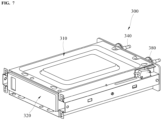
FIG. 7 is a perspective view showing a water supply device of one embodiment; -
FIG. 8 is a perspective view showing that a water tank of the water supply device ofFIG. 7 is withdrawn; -
FIG. 9 is a perspective view showing that a housing separates from the water supply device ofFIG. 7 ; -
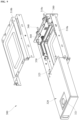
FIG. 10 is an exploded perspective view showing that the water supply device ofFIG. 7 is disassembled; -
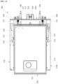
FIG. 11 is a plan view showing that a first housing is removed from the water supply device ofFIG. 7 ; -
FIG. 12 is a cross-sectional view along line "XII-XII" ofFIG. 7 ; -
FIG. 13 is a view showing that a slider is fixed in the water supply device ofFIG. 11 ; and -
FIG. 14 is a view showing that a slider separates from the water supply device ofFIG. 13 . - The above-described aspects, features and advantages are specifically described hereafter with reference to accompanying drawings such that one having ordinary skill in the art to which the disclosure pertains can embody the technical spirit of the disclosure easily. In the disclosure, detailed description of known technologies in relation to the subject matter of the disclosure is omitted if it is deemed to make the gist of the disclosure unnecessarily vague. Hereafter, preferred embodiments according to the disclosure are specifically described with reference to the accompanying drawings. In the drawings, identical reference numerals can denote identical or similar components.
- The terms "first", "second" and the like are used herein only to distinguish one component from another component. Thus, the components are not to be limited by the terms. Certainly, a first component can be a second component, unless stated to the contrary.
- Embodiments are not limited to the embodiments set forth herein, and can be modified and changed in various different forms. The embodiments in the disclosure are provided such that the disclosure can be through and complete and fully convey its scope to one having ordinary skill in the art. Accordingly, all modifications, equivalents or replacements within the technical scope of the disclosure as well as a replacement of the configuration of any one embodiment with the configuration of another embodiment or an addition of the configuration of any one embodiment to the configuration of another embodiment are to be included in the scope of the disclosure.
- The accompanying drawings are provided for a better understanding of the embodiments set forth herein and are not intended to limit the technical disclosure. It is to be understood that all the modifications, equivalents or replacements within the technical scope of the disclosure are included in the scope of the disclosure. The sizes or thicknesses of the components in the drawings are exaggerated or reduced to ensure ease of understanding and the like. However, the protection scope of the subject matter of the disclosure is not to be interpreted in a limited way, because of the exaggerated or reduced thicknesses and sizes of the components.
- The terms in the disclosure are used only to describe specific embodiments and not intended to limit the subject matter of the disclosure. In the disclosure, singular forms include plural forms as well, unless explicitly indicated otherwise. In the disclosure, the terms "comprise", "being comprised of" and the like specify the presence of stated features, integers, steps, operations, elements, components or combinations thereof but do not imply the exclusion of the presence or addition of one or more other features, integers, steps, operations, elements, components or combinations thereof.
- The terms "first", "second" and the like are used herein only to distinguish one component from another component, and the components are not to be limited by the terms.
- When any one component is described as being "connected" or "coupled" to another component, any one component can be directly connected or coupled to another component, but an additional component can be "interposed" between the two components. When any one component is described as "being directly connected" or "being directly coupled" to another component, an additional component cannot be "interposed" between the two components.
- When any one component is described as being "on (or under)" another component, any one component can be directly on (or under) another component, and an additional component can be interposed between the two components.
- Unless otherwise defined, all the terms including technical or scientific terms used herein have the same meaning as commonly understood by one having ordinary skill in the art. Additionally, terms such as those defined in commonly used dictionaries are to be interpreted as having a meaning that is consistent with their meaning in the context of the relevant art, and unless explicitly defined herein, are not to be interpreted in an ideal way or an overly formal way.
- In the state where a cooking appliance stands on a floor, a direction in which a door is installed with respect to the center of the cooking appliance is defined as a forward direction. Accordingly, a direction toward the inside of the cooking appliance with the door open is defined as a rearward direction. For convenience, the forward direction and the rearward direction can be referred to as a first direction. Then the forward direction can be referred to as one direction of the first direction, and the rearward direction can be referred to as the other direction of the first direction.
- Additionally, a gravitational direction can be defined as a downward direction, and a direction opposite to the gravitational direction can be defined as an upward direction.
- Further, a horizontal direction across a front-rear direction of the cooking appliance, i.e., a widthwise direction of the cooking appliance that is seen in front of the door of the cooking appliance, can be referred to as a left-right direction. For convenience, the left-right direction can be referred to as a second direction. Then the right side can be referred to as one side of the second direction, and the left side can be referred to as the other side of the second direction.
- Further, the widthwise direction of the cooking appliance can also be referred to as a lateral direction. Then the right side can also be referred to as one side of the lateral direction, and the left side can be referred to as the other side of the lateral direction.
- Additionally, the up-down direction can be referred to as a third direction. Then an upward direction can be referred to as one direction of the third direction, and the downward direction can be referred to as the other direction of the third direction.
- Furthermore, the up-down direction can be referred to as a vertical direction. Then the front-rear direction and the left-right direction, i.e., the first direction and the second direction, can be referred to as a horizontal direction.
- Throughout the disclosure, the terms "A and/or B" as used herein can denote A, B or A and B, and the terms "C to D" can denote C or greater and D or less, unless stated to the contrary.
-
FIG. 1 is a perspective view showing a cooking appliance of one embodiment,FIG. 2 is a lateral cross-sectional view showing the inner structure of the cooking appliance ofFIG. 1 , andFIG. 3 is a perspective view showing the cooking appliance ofFIG. 1 with a cooking compartment open. Additionally,FIG. 4 is a perspective view showing the cooking appliance ofFIG. 1 with a control panel open, andFIG. 5 is a plan view showing the inner structure of an electronic component compartment of the cooking appliance ofFIG. 1 . - Referring to
FIGS. 1 to 4 , the exterior of the cooking appliance of one embodiment is formed by amain body 100. Themain body 100 may have a shape comprising an approximate rectangular cuboid shape. Themain body 100 may be made of a material having a predetermined strength, to protect a plurality of components installed in the inner space of themain body 100. - The
main body 100 may comprise acavity 110. Thecavity 110 may form the skeleton of themain body 110. - Additionally, the
main body 100 may further comprisefront panels front panel 120 as one of thefront panels - The first
front panel 120 may be disposed between thecavity 110 and adoor 150. The firstfront panel 120 may be disposed at the front side of thecavity 110 and form the front surface of themain body 100. - In another example, the first
front panel 120 is not formed apart from thecavity 110, and the front surface of thecavity 110 may form the front surface of themain body 100. - For example, the
cavity 110 and the firstfront panel 120 may be provided at themain body 100 in a way that thecavity 110 and the firstfront panel 120 are integrally formed. - A
cooking compartment 101 may be formed in thecavity 110. Additionally, an open part may be formed inside the firstfront panel 120 and open the cooking compartment forward. - The
cooking compartment 101 may be shaped into a cuboid the front surface of which is open. With thecooking compartment 101 closed, the cooking appliance may heat the inner space of thecooking compartment 101 to cook a food item. - That is, the inner space of the
cooking compartment 101 may be a space in which a food item is substantially cooked, in the cooking appliance. Hereafter, the cooking appliance of the present disclosure is described with reference to a cooking appliance as an example. - The cooking appliance may be provided with a heating part that heats the
cooking compartment 101. As an example of the heating part, aconvection part 160 may be provided at the rear side of thecooking compartment 101 and perform convection of hot air to heat the inner space of thecooking compartment 101. - Additionally, an upper heater or an upper burner may be provided as an
upper heating part 165, at the upper side of thecooking compartment 101, and heat the inner space of thecooking compartment 101 from above. Further, a lower heater or a lower burner may be provided as a heating part, at the lower side of thecooking compartment 101, and heat the inner space of thecooking compartment 101 from below. - A
door 150 may be swivably provided at the front side of themain body 100 and selectively open and close thecooking compartment 101. Thedoor 150 may open and close thecooking compartment 101 in a pull-down manner where the upper end of thedoor 150 swivels around the lower end thereof in the up-down direction. - The
door 150 may be shaped into a cuboid and have a predetermined thickness, as a whole. Additionally, ahandle 155 may be provided on the front surface of thedoor 150, and gripped by the user when the user wants to swivel thedoor 150. - Further, the
door 150 may be provided with a see-through window. The see-through window may be made of a transparent material, e.g., glass or colorless plastic and the like. Depending on a cooking appliance to which a see-through window is applied, a see-through window may need to withstand high temperature and high pressure and have water resistance, heat resistance and the like. - An
electronic component compartment 103 may be provided outside thecavity 110, specifically, at the upper side of thecavity 110, as illustrated inFIGS. 2 and5 . Theelectronic component compartment 103 may be disposed at the upper side of thecavity 110 and at the upper side of thecooking compartment 101 formed inside thecavity 110. - A space for installing electronic components may be formed inside the
electronic component compartment 103. That is, in the cooking appliance, theelectronic component compartment 103 may be a space for installing electronic components. - As illustrated in
FIGS. 3 to 5 , the front surface of theelectronic component compartment 103 may be shielded by thefront panels front panel 130 as one of thefront panels - The second
front panel 130 may be disposed between theelectronic component compartment 103 and thecontrol panel 200, while blocking the front side of theelectronic component compartment 103. - In an example, the second
front panel 130 may be disposed at the upper side of the firstfront panel 120, and coupled to the firstfront panel 120. - The second
front panel 130 may protrude upward from thecavity 110 and define the front boundary surface of theelectronic component compartment 103. Specifically, most of the front side of theelectronic component compartment 103 is blocked by the secondfront panel 130. Additionally, a portion of the front side of theelectronic component compartment 103, i.e., a portion of the lower side of theelectronic component compartment 103, may be blocked by the firstfront panel 120. - Further, an exhaust opening may be provided on the
front panels front panel 120, for example. - The exhaust opening may be formed in a way that penetrates the first
front panel 120 in the front-rear direction. The exhaust opening may form a passage on thefront panel 120, and allow air in theelectronic component compartment 103 to pass through the firstfront panel 120 and to be discharged out of theelectronic component compartment 103. - In another example, the
front panel cavity 110, and the front surface of thecavity 110 may form the front surface of themain body 100. At this time, the exhaust opening may be provided on the front surface of thecavity 110 having a space corresponding to the shape of thefront panel - A
control panel 200 may be provided in the upper portion of the front surface of the cooking appliance, i.e., on the front surface of the upper portion of thecavity 110. Thecontrol panel 200 may form a portion of the exterior of the front surface of the cooking appliance. - The
control panel 200 may be disposed at the front of theelectronic component compartment 103. Additionally, thecontrol panel 200 may be disposed at the front side of the secondfront panel 130. - The
control panel 200 may be provided to open and close theelectronic component compartment 103 or the secondfront panel 130. Thecontrol panel 200 may be provided in a way that thecontrol panel 200 swivels between a closing position where thecontrol panel 200 blocks theelectronic component compartment 103 or the secondfront panel 130, and an opening position where thecontrol panel 200 opens theelectronic component compartment 103 or the secondfront panel 130 forward. - A display may be provided on the
control panel 200. The display may comprise an input part for adjusting an operation of the cooking appliance and a display displaying an operation state of the cooking appliance. - In an example, the input part and the display may be constituted by one panel. For example, the input part and the display may be formed into a touch panel to which a touch input of the user is supplied. The display may display a user interface (UI) or a graphic user interface (GUI) in relation to the driving of the cooking appliance.
- A plurality of buttons may be displayed on the
control panel 200 with the above display. For example, a knock-on button may be displayed on thecontrol panel 200, and used to set a function that enables the on/off of a lamp 190 installed in thecooking compartment 130, based on a knock input of the user. - Additionally, a lamp button for setting a function of turning on/off a lamp manually, a button for setting an opening and closing operation of the
control panel 200 and the like may be displayed on thecontrol panel 200. - In the case where the cooking appliance is an oven, a button for setting an operation of the heating part, a self-cleaning button for setting a self-cleaning function of the
cooking compartment 130, and the like may be displayed on thecontrol panel 200. - Referring to
FIGS. 2 to 5 , the lower boundary surface of theelectronic component compartment 103 may be defined by anupper panel 140 disposed at the upper side of thecavity 110. Additionally, the upper boundary surface of theelectronic component compartment 103 may be defined by an electroniccomponent compartment cover 145 that covers theelectronic component compartment 103 from above. - Further, the lateral boundary surfaces and the rear boundary surface of the
electronic component compartment 103 may be defined by the electroniccomponent compartment cover 145's both lateral surfaces and rear surface, or defined by both lateral surfaces of thecavity 110 protruding toward the upper side of thecooking compartment 101 and by the rear surface of the electroniccomponent compartment cover 145. - A
vent hole 104 may be formed on at least any one of both the lateral surfaces and the rear surface of the electroniccomponent compartment cover 145, and both the lateral surfaces of thecavity 110. Through thevent hole 104, external air may flow into theelectronic component compartment 103. - As described above, a variety of electronic components may be disposed in the
electronic component compartment 103. In an example, a circuit board may be disposed in theelectronic component compartment 103. Various types of elements, circuits and the like in relation to the receipt of a manipulation signal input through thecontrol panel 200, the generation of a control signal for controlling an operation of the heating part, input through thecontrol panel 200, and the like may be provided on the circuit board. - The
upper panel 140 may comprise a blockingplate part 141 and aduct part 143. - The blocking
plate part 141 may be disposed to block between thecavity 110 and theelectronic component compartment 103. The blockingplate part 141 may be disposed at the upper side of thecavity 110 and define the lower boundary surface of theelectronic component compartment 103. - The
duct part 143 may protrude upward from the blockingplate part 141. Theduct part 143 may form a passage that allows air in theelectronic component compartment 103 to be discharged out of theelectronic component compartment 103 through theduct part 143. That is, theduct part 143 may form a passage that allows air suctioned by afan module 170 described hereafter to flow to the exhaust opening. - The
fan module 170 may be disposed in theelectronic component compartment 103. Thefan module 170 may be disposed near the rear surface of thecavity 110, i.e., in a position eccentric to the rear side in theelectronic component compartment 103. - The
fan module 170 may comprise a turbo fan that is installed in theelectronic component compartment 103. Thefan module 170 may suction external air through the rear side of theelectronic component compartment 103, and discharge the external air to the front side of theelectronic component compartment 103. - Based on an operation of the
fan module 170, external air may flow into theelectronic component compartment 103 from the rear side and lateral sides of the cooking appliance. - For example, external air drawn through the lower portion of the
main body 100 may pass through a space at the rear side of the cooking appliance, and then flow into theelectronic component compartment 103 through thevent hole 104 formed at the rear side of theelectronic component compartment 103. Also, external air may flow into theelectronic component compartment 103, through thevent hole 104 formed at a lateral side of theelectronic component compartment 103. - Air drawn into the
electronic component compartment 103 may cool electronic components in theelectronic component compartment 103, while moving forward in theelectronic component compartment 103. - Air drawn into the
electronic component compartment 103 as described above may be suctioned into theduct part 143 by thefan module 170. The air drawn into theduct part 143 may move forward in theduct part 143 and then be discharged to the front of theelectronic component compartment 103 through the exhaust opening. - A
water supply device 300 may be disposed in theelectronic component compartment 103. Thewater supply device 300 may supply water, needed to generate steam in a steam supply device (not illustrated), to the steam supply device. -
FIG. 6 is a block diagram showing the configuration of a steam supply device of one embodiment. - The cooking appliance of the embodiment, as illustrated in
FIGS. 5 and6 , may further comprise asteam supply device 30. - The
steam supply device 30 is installed in themain body 100 and provided to supply steam into thecooking compartment 101. Thesteam supply device 30 may comprise asteam generator 31, awater supply device 300 and aconnection pipe 35. - The
steam generator 31 is provided to heat water and generate steam. In an example, thesteam generator 31 may be disposed at the lower side of themain body 100, and disposed at the lower side of thecooking compartment 101. - However, the steam generator of the present disclosure is not limited. The
steam generator 31 may be disposed in any optimal position considering a detailed configuration of thesteam generator 31, the structure of thecooking compartment 101 and steam supply efficiency based on the configuration and the structure. - The
steam generator 31 may comprise awater storage 32 and asteam heater 33. Water that is supplied from thewater supply device 300 through theconnection pipe 35 may be stored in thewater storage 32. Thesteam heater 33 may generate steam by heating the water stored in thewater storage 32. - The
water supply device 300 is provided to store and supply water that is supplied to thesteam generator 31. In the embodiment, thewater supply device 300 is disposed at the upper side of themain body 100 and disposed at the upper side of thecooking compartment 101, for example. - However, the water supply device of the present disclosure is not limited. The
water supply device 300 may be disposed in any position where thewater supply device 300 is not greatly affected by heat in a high-temperature cooking compartment 101, awater tank 320 is readily withdrawn, and water is supplied to thesteam generator 31 smoothly. - The
connection pipe 35 may connect thewater supply device 300 and thesteam generator 31. Theconnection pipe 35 may form a passage that is needed to allow water supplied from thewater supply device 300 to move to thesteam generator 31. - In an example, the
connection pipe 35 may be formed as a flexible tube. In another example, theconnection pipe 35 may be formed as a pipe made of a metallic material. - Additionally, the
connection pipe 35 may connect to thesteam generator 31 by bypassing thecooking compartment 101 from thewater supply device 300. In an example, theconnection pipe 35 may connect to thesteam generator 31 through a path in which theconnection pipe 35 bypasses the rear side of thecooking compartment 101. In another example, theconnection pipe 35 may connect to thesteam generator 31 through a path in which theconnection pipe 35 bypasses a lateral side of thecooking compartment 101. - At this time, water may be supplied from the
water supply device 300, based on force caused by a difference between the height or pressure of thewater supply device 300 and the height or pressure of thewater storage 32, or power of apump 36 disposed at thewater storage 32 side or theconnection pipe 35 side. - Further, the
steam supply device 30 may further comprise asteam spray member 39. Thesteam spray member 39 is provided to spray steam generated by thesteam supplier 31 into the cooking compartment 15. - The
steam spray member 39 may be provided on the upper surface of thecavity 110, and connect to thewater storage 32 of thesteam supplier 31 through asteam pipe 38. Thesteam spray member 39 may form a passage that allows steam generated by thesteam supplier 31 to spray downward from the upper portion of the cooking compartment 15 to the inside of the cooking compartment 15. - In the cooking appliance of the present disclosure, water supplied from the
water supply device 300 may flow into thewater storage 32 through theconnection pipe 35, and the water having flown into thewater storage 32 may be heated by thesteam heater 33 to generate steam. - The generated steam may flow into the
cooking compartment 101 through thesteam spray member 39 and circulate in thecooking compartment 101. The steam circulating in thecooking compartment 101 may be used to perform cooking in the cooking appliance. -
FIG. 7 is a perspective view showing a water supply device of one embodiment, andFIG. 8 is a perspective view showing that a water tank of the water supply device ofFIG. 7 is withdrawn.FIG. 9 is a perspective view showing that a housing separates from the water supply device ofFIG. 7 , andFIG. 10 is an exploded perspective view showing that the water supply device ofFIG. 7 is disassembled. - Referring to
FIGS. 5 to 8 , thewater supply device 300 may comprise ahousing 310 and awater tank 320. - The
housing 310 may be disposed in theelectronic component compartment 103. Thehousing 103 may be coupled to theupper panel 140 and fixed to the inside of theelectronic component compartment 103. - The
housing 310 may be shaped into a box having an accommodation space therein. Thehousing 310 may form a skeleton needed to accommodate and install a variety of components constituting thewater supply device 300. Additionally, thehousing 310 may serve as a coupling medium for coupling thewater supply device 300 to themain body 100. - In the embodiment, the
housing 310 may be shaped into a cuboid box having an accommodation space therein, for example. The front surface of thehousing 310 may be open forward. The accommodation space formed in thehousing 310 may be open forward through the front surface of thehousing 310. - A
water tank 320 and aslider 330 described hereafter may be accommodated in the accommodation space of thehousing 310. The open front surface of thehousing 310 may be a passage that allows thewater tank 320 installed in thehousing 310 to be drawn out of thehousing 310 and themain body 100. - The
water tank 320 is provided to store water. A storage space for storing water may be formed in thewater tank 320. Water stored in thewater tank 320 may be supplied to thesteam generator 31 through theconnection pipe 35. - The
water tank 320 may be installed in thehousing 310 in a way that thewater tank 320 can come into and out of thehousing 310 in the front-rear direction. Thewater tank 310 may move forward and protrude to the front of thehousing 310, or move rearward and come into thehousing 310 completely. - The
water supply device 300 may further comprise aslider 330. Theslider 330 may be disposed in the accommodation space of thehousing 310. Theslider 330 may be accommodated in thehousing 310 in a way that theslider 330 can move in the front-rear direction. - The
slider 330 may connect to thewater tank 320 in thehousing 310 and move together with thewater tank 320. For example, thewater tank 320 may connect to theslider 330 such that thewater tank 320 may move forward together with theslider 330. Additionally, theslider 330 may connect to thewater tank 320 such that theslider 330 may move rearward together with thewater tank 320. - In an example, the
water tank 320 may be moved forward by theslider 330 that moves forward, and theslider 330 may move rearward by thewater tank 320 that moves rearward. - A detailed structure and a detailed operation of the
slider 330 are described hereafter. - Referring to
FIGS. 8 to 10 , thehousing 310 may comprise afirst housing 310a and asecond housing 310b. - The
first housing 310a may form a lower half of thehousing 310. Thefirst housing 310a may comprise abottom surface part 311 and a pair of firstlateral surface parts 312. - The
bottom surface part 311 may form the bottom surface of thehousing 310, and be disposed at the lower side of thewater tank 320. Thebottom surface part 311 may be disposed to face the bottom surface of thehousing 310. - At least a portion of the
bottom surface part 311 may form a horizontal planar surface parallel with the bottom surface of thewater tank 320. Thebottom surface part 311 may support thewater tank 320 at the lower side of thewater tank 320 in a way that thewater tank 320 can move in the front-rear direction. - In an example, a first sliding
projection 323 may be provided in the lower portion of thewater tank 320. The first slidingprojection 323 may be formed in a way that the first slidingprojection 323 protrudes downward from the bottom surface of thewater tank 320. - A pair of first sliding
projections 323 may be disposed at thewater tank 320 and spaced a predetermined distance apart from each other in the lateral direction. The lateral length of each of the first slidingprojections 323 may be much less than a lateral length of thebottom surface 311 of thehousing 310. That is, the first slidingprojection 323 may be shaped into a long thin rod. - In the embodiment, the entire bottom surface of the
water tank 320 may contact thebottom surface part 311 through the first slidingprojection 323, without contacting thebottom surface part 311. That is, an area where the bottom surface of thewater tank 320 contacts thehousing 310 may be limited to an area where the first slidingprojection 323 contacts thebottom surface part 311. - The first sliding
projection 323 formed as describe above may help to reduce an area of contact between thehousing 310 and thewater tank 320, to reduce a frictional force that is generated at a time when thewater tank 320 moves. - Additionally, the first
lateral surface parts 312 may form a portion of the lateral surfaces of thehousing 312 and connect to thebottom surface part 311. The pair of firstlateral surface parts 312 may extend upward from the end portions of both sides of thebottom surface part 311, and each of the firstlateral surface parts 312 may be disposed in the lateral portions of thewater tank 320. - The
first housing 310a may further a firstguide surface part 313. The firstguide surface part 313 may extend in a direction far from thebottom surface part 311, while extending from the firstlateral surface part 312 in the lateral direction. - The first
guide surface part 313 may be formed in a way that the firstguide surface part 313 extends from the upper end of the firstlateral surface part 312 in the lateral direction. The firstguide surface part 313 may be spaced from thebottom surface part 311 by the up-down length of the firstlateral surface part 312, while being disposed at the upper side of thebottom surface part 311. - In an example, at least a portion of the
bottom surface part 311 may form a horizontal planar surface parallel with the bottom surface of thewater tank 320. Further, the firstguide surface part 313 may form a planar surface parallel with a horizontal planar surface formed at thebottom surface part 311. - In the embodiment, the
bottom surface part 311 may support thewater tank 320 at the lower side of thewater tank 320 in a way that thewater tank 320 can move in the front-rear direction. Additionally, the firstguide surface part 313 disposed at the upper side of thebottom surface part 311 may support theslider 330 at the lower side of theslider 330 described hereafter, in a way that theslider 330 can move in the front-rear direction. - The
second housing 310b may form an upper half of thehousing 310. Thefirst housing 310a and thesecond housing 310b may be formed separately, and may be coupled to each other in the up-down direction to form thehousing 310. - In an example, the
second housing 310a may have a shape that is almost similar to a shape in which thefirst housing 310a is reversed in the up-down direction. Thesecond housing 310b may comprise anupper surface part 315 and a pair of secondlateral surface parts 316. - The
upper surface part 315 may from the upper surface of thehousing 310, and be disposed at the upper side of thewater tank 320. The secondlateral surface parts 316 may form a portion of the lateral surfaces of thehousing 310, and connect to theupper surface part 315. The pair of secondlateral surface parts 316 may extend downward from the end portions of both sides of theupper surface part 315, and each of the secondlateral surface parts 316 may be disposed in the lateral portion of thewater tank 316. - Further, the
second housing 310b may further comprise a secondguide surface part 317. The secondguide surface part 317 may extend in a direction far from theupper surface part 315, while extending from the secondlateral surface part 316 in the lateral direction. - The second
guide surface part 317 may be formed in a way that the secondguide surface part 317 extends from the lower end of the secondlateral surface part 316 in the lateral direction. The secondguide surface part 317 may be spaced from theupper surface part 315 by the up-down length of the secondlateral surface part 316, while being disposed at the lower side of theupper surface part 315. - Further, the
first housing 310a may comprise a firstcoupling surface part 314, and thesecond housing 310b may comprise a secondcoupling surface part 318. The firstcoupling surface part 314 may be disposed respectively in both lateral portions of thefirst housing 310a, and the secondcoupling surface part 318 may be respectively disposed in both lateral portions of thesecond housing 310b. - The first
coupling surface part 314 may be formed to extend upward from the end portion of the firstguide surface part 313 in the lateral direction thereof. Further, the secondcoupling surface part 318 may be formed to extend downward from the end portion of the secondguide surface part 317 in the lateral direction thereof. - The first
coupling surface part 314 and the secondcoupling surface part 318 may be disposed to touch each other in the lateral direction. In the state where the firstcoupling surface part 314 and the secondcoupling surface part 318 are touched in the lateral direction as described above, the firstcoupling surface part 314 and the secondcoupling surface part 318 may be coupled. - The first
coupling surface part 314 and the secondcoupling surface part 318 may be coupled in both lateral portions of thehousing 310, and based on a coupling between firstcoupling surface part 314 and the secondcoupling surface part 318, thefirst housing 310a and thesecond housing 310b maybe coupled. - In the state where the
first housing 310a and thesecond housing 310b are coupled, thebottom surface part 311 and theupper surface part 315 may be spaced from each other by an approximate up-down length of thewater tank 320, and the firstguide surface part 313 and the secondguide surface part 317 may be spaced from each other by an approximate up-down length of theslider 330. - That is, the
water tank 320 may be accommodated in a space formed between thebottom surface part 311 and theupper surface part 315, and theslider 330 may be accommodated in a space formed between the firstguide surface part 313 and the secondguide surface part 317. - In the space formed between the
bottom surface part 311 and theupper surface part 315, thebottom surface part 311 may support thewater tank 320 in a way that thewater tank 320 can move in the front-rear direction. In the space formed between the firstguide surface part 313 and the secondguide surface part 317, the firstguide surface part 313 may support theslider 330 in a way that theslider 330 can move in the front-rear direction. - The
housing 310 may further comprise arear surface cover 310c. Therear surface cover 310c may be disposed at the rear sides of thefirst housing 310a and thesecond housing 310b. - In a coupled body of the
first housing 310a and thesecond housing 310b, the front surface and the rear surface of the coupled body are open. Therear surface cover 310c may cover the open rear surface of the coupled body of thefirst housing 310a and thesecond housing 310b, and form the rear surface of thehousing 310. Therear surface cover 310c may be disposed at the rear side of theslider 330 accommodated in thehousing 310. - Preferably, at least a portion of the
housing 310 may made of a metallic material. In the embodiment, thefirst housing 310a and thesecond housing 310b may be made of a metallic material, and therear surface cover 310b comprising a structure of a complex shape may be made of a plastic material, for example. - The
first housing 310a and thesecond housing 310b made of a metallic material may be highly resistance against heat that is delivered through thecavity 110. Further, thefirst housing 310a and thesecond housing 310b may be made of a metallic material having enough stiffness to protect thewater tank 320 and theslider 330 from an external impact. - In an example, the
water tank 320 may be shaped into a cuboid box. For example, thewater tank 320 may be shaped into a cuboid box corresponding to the shape of the accommodation space in thehousing 310. - The
water tank 320 may be installed in a way that thewater tank 320 is movable in the front-rear direction, while being installed in thehousing 310. Thewater tank 320 may be installed in thehousing 310, such that the entire area of thewater tank 320 may be disposed in the accommodation space of thehousing 310, and may be withdrawn out of thehousing 310 and themain body 100 through the open front surface of thehousing 310. - In the embodiment, the
water tank 320 may be installed in thehousing 310 in a way that the position of thewater tank 320 is changeable to an insertion position and a withdrawal position. - In the embodiment, the insertion position is defined as a position of the
water tank 320, at a time when the entire area of thewater tank 320 is inserted into the accommodation space of thehousing 310. In the case where thewater tank 320 is in the insertion position, an input hole and alid 321 that are disposed near the front surface of thewater tank 320 may be disposed in the accommodation space of thehousing 310. - Additionally, in the embodiment, the withdrawal position is defined as a position of the
water tank 320, at a time when at least a partial area of thewater tank 320 protrudes to the front sides of the accommodation space and themain body 100. In the case where thewater tank 320 is in the withdrawal position, at least a portion of the input hole and thelid 321 of thewater tank 320 may be exposed out of the accommodation space and themain body 100. - In the insertion position, the
water tank 320 may be disposed in theelectronic component compartment 103 and thehousing 310. Thewater tank 320 may move to the withdrawal position while passing through thefront panel water tank 320 may be withdrawn forward from the cooking appliance while passing through the secondfront panel 130. - Further, the input hole may be formed in the upper portion of the
water tank 320. The input hole may form a passage for inputting water to a storage space from the outside of thewater tank 320, at thewater tank 320, and may be disposed in a way that the input hole is eccentric to the front side of thewater tank 320. - The
lid 321 may be disposed at the upper side of the input hole. Thelid 321 may be provided to open and close the input hole at the upper side of the input hole. - A
water tank nozzle 325 may be provided at thewater tank 320. Thewater tank nozzle 325 may form a passage for allowing water stored in the storage space of thewater tank 320 to move out of thewater tank 320. At least a portion of thewater tank nozzle 325 may protrude from the rear of thewater tank 320. - The portion of the
water tank nozzle 325, which is exposed to the outside, is formed to protrude from the rear side of thewater tank 320 to face the rear surface of thehousing 310. Further, atube supporter 340 may be provided on the rear surface of thehousing 310. - The
tube supporter 340 may be disposed at therear surface cover 310c. Thetube supporter 340 may be provided in a way that thetube supporter 340 is detachably coupled to thewater tank nozzle 325. - In an example, the
tube supporter 340 may be disposed in a way that the tube supporter 304 penetrates therear surface cover 310c in the front-rear direction, while being disposed at therear surface cover 310c. The anterior portion of thetube supporter 340 may be exposed to thewater tank 320 side, and coupled detachably to thewater tank nozzle 325. The posterior portion of thetube supporter 340 may connect to theconnection pipe 35. That is, thewater tank nozzle 325 and theconnection pipe 35 may connect to each other based on their connection with thetube supporter 340. - The
tube supporter 340 may further comprise a gasket. The gasket may seal between thewater tank nozzle 325 and thetube supporter 340 to prevent the leakage of water from between thewater tank nozzle 325 and thetube supporter 340. - The
water tank nozzle 325 may be coupled to thetube supporter 340 at a time when thewater tank 320 is in the insertion position. At a time when thewater tank nozzle 325 is coupled with thetube supporter 340, thewater tank nozzle 325 and theconnection pipe 35 may connect to each other, making it possible to supply water to thesteam generator 31. - In the case where the
water tank 320 moves to the withdrawal position, thewater tank nozzle 325 may be decoupled from thetuber supporter 340. As thewater tank nozzle 325 is decoupled from thetube supporter 340, thewater tank nozzle 325 and theconnection pipe 35 are disconnected from each other, and the supply of water to thesteam generator 31 may be cut off. -
FIG. 11 is a plan view showing that a first housing is removed from the water supply device ofFIG. 7 , andFIG. 12 is a cross-sectional view along line "XII-XII" ofFIG. 7 . - Referring to
FIGS. 9 to 12 , thewater supply device 300 of the embodiment may further comprise aslider 330. Theslider 330 may be accommodated in thehousing 310 in a way that theslider 330 can move in the front-rear direction, and comprise arear surface frame 331. - The
rear surface frame 331 may be disposed at the rear side of thewater tank 320. Therear surface frame 331 may be shaped into a horizontal bar that extends in the lateral direction, and disposed to touch the rear surface of thewater tank 320. - The
slider 330 may further comprise a pair of lateral surface frames 335. Each of the lateral surface frames 335 may extend forward from therear surface frame 331 and be disposed to face the lateral surface of thewater tank 320. The pair of lateral surface frames 335 formed as described above may be spaced from each other in the lateral direction, with thewater tank 320 therebetween. - In an example, the
slider 330 may be formed in a way that therear surface frame 331 and the pair of lateral surface frames 335 connect in a "" shape. As the
water tank 320 and theslider 330 connect, at least a portion of thewater tank 320 may be inserted into a space that is surrounded by therear surface frame 331 and the pair of lateral surface frames 335. - As the
water tank 320 and theslider 330 connect as described above, therear surface frame 331 may contact the rear surface of thewater tank 320 closely, and each of the lateral surface frames 335 may contact each of the lateral surfaces of thewater tank 320 closely. - Additionally, as the
water tank 320 and theslider 330 connect as described above, thewater tank 320 is not fixed to theslider 330 or theslider 330 is not fixed to thewater tank 320. In the embodiment, thewater tank 320 and theslider 330 may keep connecting to each other, only in the state where a portion of thewater tank 320 is inserted into the space surrounded by therear surface frame 331 and the pair of lateral surface frames 335. - The
water tank 320 and theslider 330 connected as described above may move together, when necessary, while separating from each other readily. In an example, thewater tank 320 may keep connecting to theslider 330, such that thewater tank 320 moves together with theslider 330 or theslider 330 moves together with thewater tank 320. - For example, in the case where the
slider 330 moves forward at a time when thewater tank 320 is in the insertion position, thewater tank 320 may move together with theslider 330. At this time, therear surface frame 331 disposed at a rear side of thewater tank 320 may push and move thewater tank 320 forward, and thewater tank 320 may move forward toward the insertion position. - Additionally, in the case where the
water tank 320 moves rearward when thewater tank 320 is in the insertion position, theslider 330 may move together with thewater tank 320. At this time, thewater tank 320 may push and move therear surface frame 331 rearward, and theslider 330 may move rearward together with thewater tank 320 that moves toward the insertion position. - A portion of the
slider 330, specifically, the pair of lateral surface frames 335, may be accommodated in the space formed between the firstguide surface part 313 and the secondguide surface part 317. That is, each of the lateral surface frames 335 may be accommodated in the space that is surrounded by the firstguide surface part 313, thecoupling surface part guide surface part 317. - Each of the lateral surface frames 335 accommodated in the space may be supported by the first
guide surface part 313 in a way that thelateral surface frame 335 is movable in the front-rear direction. - In an example, a second sliding
projection 336 may be provided in the lower portion of thelateral surface frame 335. The second slidingprojection 336 may be formed in a way that protrudes downward from the bottom surface of thelateral surface frame 335. - The lateral length of each of the second sliding
projections 336 may be much less than the lateral length of thebottom surface 311 of thehousing 310 or the lateral length of the bottom surface of thelateral surface frame 335. That is, the second slidingprojection 336 may be shaped into a long thin rod. - The entire bottom surface of the
lateral surface frame 335 may contact the firstguide surface part 313 through the second slidingprojection 336, without contacting the firstguide surface part 313. That is, an area where thelateral surface frame 335 and the firstguide surface part 313 contact each other may be limited to an area where the second slidingprojection 336 and the firstguide surface part 313 contact each other. - The second sliding
projection 336 formed as described above may help to reduce a contact area between thehousing 310 and theslider 330, thereby reducing a frictional force that is generated as theslider 330 moves. - Further, a
rail projection 313a may be provided in thehousing 310. Therail projection 313a may be respectively formed on the firstguide surface part 313. That is, in thehousing 310, a pair ofrail projections 313a may be spaced a predetermined distance apart from each other in the lateral direction. Each of therail projections 313a may protrude upward from thefirst guide surface 313, and extend in the front-rear direction. - An up-down length of the
rail projection 313a may be less than an up-down length of the second slidingprojection 336. That is, the second slidingprojection 336 may contact the firstguide surface part 313, while therail projection 313a does not contact the bottom surface of thelateral surface frame 335. - A lateral gap between the pair of
rail projections 313a may be greater than a lateral gap between the pair of second slidingprojections 336. Further, the pair of second slidingprojections 336 provided at theslider 330 may be disposed between the pair ofrail projections 313a. - The second sliding
projection 336 disposed between the pair ofrail projections 313a as described above may move in the front-rear direction within an area limited between the pair ofrail projections 313a. That is, therail projection 313a may regulate the area where therail projection 313a moves, and suppress a shake of therail projection 313a while therail projection 313a moves in the front-rear direction. - The
slider 330 comprising the pair of lateral surface frames 335 that sit in the firstguide surface part 313 in a slidable manner may be installed in thehousing 310 in a way that theslider 330 is movable in the front-rear direction. - Each of the lateral surface frames 335 may be disposed between the first
guide surface part 313 and the secondguide surface part 317, and the firstguide surface part 313 and the secondguide surface part 317 may regulate an up-down position of eachlateral surface frame 335. - For example, an up-down gap between the first
guide surface part 313 and the secondguide surface part 317 may be set to a length corresponding to an up-down length of thelateral surface frame 335. The firstguide surface part 313 and the secondguide surface part 318 disposed as described above may help to suppress the generation of an up-down flow of theslider 330, and guide a front-rear movement of theslider 330 smoothly. - The
water supply device 300 of the embodiment may further comprise afixation part 350. Thefixation part 350 may be disposed on the rear surface of thehousing 310. In an example, thefixation part 350 may be disposed at therear surface cover 310c. - The
fixation part 350 may be provided to fix theslider 330. Theslider 330 may be accommodated in thehousing 310 in a way that theslider 330 is movable in the front-rear direction. Thefixation part 350 may fix theslider 330 to prevent theslider 330 from moving forward. - As the
water tank 320 moves to the insertion position, theslider 330 may be fixed by thefixation part 350. Additionally, as theslider 330 is fixed by thefixation part 350, thewater tank 320 may remain in the insertion position. - A
fixation projection 332 may be provided at theslider 330. Thefixation projection 332 may be provided at therear surface frame 331 and protrude to the rear of theslider 330. In the embodiment, thefixation projection 332 is shaped into a hook that protrudes rearward from therear surface frame 331, for example. - As the
water tank 320 moves to the insertion position, theslider 330 connecting to thewater tank 320 may move rearward together with thewater tank 320. At this time, therear surface frame 331 and thefixation projection 332 may move to be near thefixation part 350, and thefixation part 350 may be coupled to thefixation projection 332 and fix theslider 330. - The
fixation part 350 may be detachably coupled to the hook-shapedfixation projection 332, to selectively fix the positions of theslider 330 and thewater tank 320 coupled to theslider 330. - In an example, the
fixation part 350 may comprise a locking tool that enables thefixation part 350 to be fixed to and released from thefixation projection 332, based on a press manipulation. In the case of afixation part 350, a press on the front surface of thewater tank 320 connecting to thefixation projection 332 through theslider 330 is repeated, such that thefixation projection 332 and the locking tool are coupled or decoupled consecutively. - For example, in the case where the user presses the front surface of the
water tank 320 to insert thefixation projection 332 into thefixation part 350, thefixation part 350 may be coupled to thefixation projection 332 to fix theslider 330. In this state, in the case where the user presses the front surface of thewater tank 320 again, thefixation part 350 and thefixation projection 332 may be decoupled, and theslider 330 may be released. - The
water supply device 300 of the embodiment may further comprise a pop-upmember 360. The pop-upmember 360 may provide power of moving theslider 330 separated from thefixation part 350 forward. To put it another way, the pop-upmember 360 may provide power of moving thewater tank 320 to the withdrawal position. - The pop-up
member 360 may be disposed between theslider 330 and therear surface cover 310c. The pop-upmember 360 may elastically support theslider 330 at the rear side of theslider 330. - In an example, the pop-up
member 360 may comprise a coil spring disposed between therear surface frame 331 and therear surface cover 310c. The coil spring provided as a pop-upmember 360, may be deformed elastically in the front-rear direction. The end portion of the rear side of the coil spring may be supported by therear surface cover 310c, and the end portion of the front side of the coil spring may support therear surface frame 331 from rearward. - A
guide projection 333 may be provided at theslider 330. Thefixation projection 332 may be provided at therear surface frame 331 and protrude toward the rear of theslider 330. In the embodiment, thefixation projection 332 is shaped into a rod protruding rearward from therear surface frame 331, for example. - A plurality of
guide projections 333 may be disposed at theslider 330 and spaced a predetermined distance apart from each other in the lateral direction. In the embodiment, a pair ofguide projections 333 may be provided at theslider 330, for example. - In an example, the
fixation projection 332 and the pair ofguide projections 333 may be arranged at therear surface frame 331 in the lateral direction, and the pair ofguide projections 333 may be spaced from each other in the lateral direction, with thefixation projection 332 therebetween. - Preferably, the
fixation projection 332 may be disposed at the center of therear surface frame 331 in the lateral direction, and the pair offixation projections 332 may be disposed in a way that the fixation projections are symmetrical to each other in the left-right direction, with respect to thefixation projection 332. - Further, a plurality of pop-up
members 360 may be disposed between therear surface frame 331 and therear surface cover 310c. In the embodiment, a pair of pop-upmembers 360 is provided at thewater supply device 300, for example. - In an example, the pair of pop-up
members 360 may be disposed between therear surface frame 331 and therear surface cover 310c, and each of the pop-upmembers 360 may be coupled respectively to theguide projection 333. - Additionally, each
guide projection 333 may be fitted and coupled to the pop-upmember 360. Accordingly, eachguide projection 333 may be fitted into the coil spring while passing through the coil spring in the front-rear direction. - The
guide projection 333 fitted and coupled to the pop-upmember 360 may support the pop-upmember 360, such that the pop-upmember 360 may be prevented from escaping and being deformed in the lateral direction. - In the embodiment, the
fixation projection 332 may be disposed at the center of therear surface frame 331 in the lateral direction, the pair offixation projections 332 may be disposed in a way that thefixation projections 332 are symmetrical to each other in the left-right direction, with respect to thefixation projection 332, while the pair of pop-upmembers 360 may also be disposed in a way that the pop-upmembers 360 are symmetrical to each other in the left-right direction, with respect to thefixation projection 332. - Accordingly, an elastic force provided by the pop-up
member 360 is applied to theslider 330 in a way that the elastic force is not biased toward to any one of the left side and the right side. For example, a uniform power may be applied to thelateral surface frame 335 on the left side of theslider 330, and thelateral surface frame 335 on the right of theslider 330. - Further, power provided by the pop-up
member 360 may be supplied to thewater tank 320 connecting to theslider 330, in a way that the power is not biased toward any one of the left side and the right side of thewater tank 320. - Thus, the
slider 330 may smoothly move forward without biasing left or right. Thewater tank 320 being moved forward by theslider 330 may be drawn smoothly to the front of the cooking appliance in the state where thewater tank 320 remains aligned in the left-right direction. - Further, the
guide projection 333 may be coupled to thehousing 310 in a way that theguide projection 333 is movable in the front-rear direction. - In an example, the
guide projection 333 may be coupled to therear surface cover 310c while passing through therear surface cover 310c in the front-rear direction. Theguide projection 333 may be coupled to therear surface cover 310c in a way that theguide projection 333 is movable in the front-rear direction. - The
guide projection 333, coupled to therear surface cover 310c in a way that theguide projection 333 is movable in the front-rear direction as described above, may couple theslider 330 to thehousing 310 in a way that theslider 330 is movable in the front-rear direction. Theguide projection 333 may support theslider 330 to prevent theslider 330 from escaping from thehousing 310 and to allow theslider 330 to move reliably in the front-rear direction. - The
guide projection 333 may be detachably fitted and coupled to therear surface cover 310c. A plurality of hook members may be disposed in the end portion of the rear side of theguide projection 333. Each of the plurality of hook members may be provided in a way that the plurality of hook members is elastically deformable in the direction of the diameter of eachguide projection 333. - The hook members provided in the end portion of the rear side of the
guide projection 333 may be disposed at the rear side of therear surface cover 310c, and regulate a forward movement of theguide projection 333. In the case where the hook members are deformed to reduce a gap between the hook members, theslider 330 may separate from therear surface cover 310c while the end portion of the rear side of theguide projection 333 escapes from the front side of therear surface cover 310c. - Since the
slider 330 is detachably provided at thehousing 310, theslider 330 may be readily separated and mounted to repair the pop-upmember 360 or thefixation part 350 and to be replaced. - The
water supply device 300 of the embodiment may further comprise a speed-reduction inducing member 370. The speed-reduction inducing member 370 may be disposed at theslider 330. The speed-reduction inducing member 370 is provided to interfere with a front-rear movement of thewater tank 320 connecting to theslider 330, with respect to theslider 330. - In an example, the speed-
reduction inducing member 370 may be disposed at thelateral surface frame 335. The speed-reduction inducing member 370 may interfere with a front-rear movement of thewater tank 320, relative to theslider 330, while contacting the lateral surface of thewater tank 320 that is inserted into theslider 330, i.e., the lateral surface of thewater tank 320 that is disposed to face thelateral surface frame 335. - A pair of speed-
reduction inducing members 370 may be provided at theslider 330. In the embodiment, the pair of speed-reduction inducing members 370 may be spaced from each other in the lateral direction, with thewater tank 320 therebetween. Each of the speed-reduction inducing members 370 may be provided at thelateral surface frame 335. - In the embodiment, the speed-
reduction inducing member 370 comprises a roller, for example. Accordingly, the speed-reduction inducing member 370 may comprise a roller that is provided to rotate around an up-down axis. - The roller may be disposed at the
lateral surface frame 335. Preferably, the roller may be disposed in the end portion of the front side of thelateral surface frame 335, and contact the lateral surface of thewater tank 320 connecting to theslider 330. The roller may generate a frictional force that interferes with the movement of thewater tank 320. - In the embodiment, a roller may be installed such that a fictional force applied between the speed-
reduction inducing member 370 and thewater tank 320 at a time when thewater tank 320 moves may be greater than a friction force applied between the bottom surface of thewater tank 320 and thebottom surface part 311 of thehousing 310 at a time when thewater tank 320 moves. - For example, a greater fictional force may be applied between the roller and the
water tank 320 than between the bottom surface of thewater tank 320 and thebottom surface part 311 of thehousing 310, and a greater frictional force may be applied between a rotation axis rotatably supporting the roller and the roller than between the bottom surface of thewater tank 320 and thebottom surface part 311 of thehousing 310. - The speed-
reduction inducing member 370 comprising the above-described roller may reduce a speed of movement of thewater tank 320, while interfering with a front-rear movement of thewater tank 320, relative to theslider 330, in the state where the speed-reduction inducing member 370 contacts the lateral surface of thewater tank 320 closely. - In the embodiment, in the case where the
slider 330 separates from thefixation part 350, in the state where thewater tank 320 is disposed in the insertion position and theslider 330 is fixed by thefixation part 350, theslider 330 and thewater tank 320 may be moved forward by an elastic force provided by the pop-upmember 360. - At this time, the
water tank 320 may be filled with water or almost empty. In most cases, thewater tank 320 is drawn to fill thewater tank 320 with water. Accordingly, it is highly likely that thewater tank 320 is empty at a time when thewater tank 320 moves to the withdrawal position. - A
water tank 320 that is empty weighs much less than awater tank 320 that is filled with water. At a time when thewater tank 320 that is empty moves to the withdrawal position, based on the operation of the pop-upmember 360, thewater tank 320 that is empty moves faster than thewater tank 320 that is filled with water. - In the case where the
water tank 320 moves to the withdrawal position too fast, thewater tank 320 may escape forward out of the cooking appliance rapidly. - At this time, the user may be surprised by the
water tank 320 escaping and injured by thewater tank 320 falling downward, or thewater tank 320 may be damaged. - To prevent this from happening, the elastic force of the pop-up
member 360 may be reduced. However, at this time, thewater tank 320 may hardly be drawn in the case where thewater tank 320 is filled with water. - Considering the fact, in the embodiment, the speed of movement of the
water tank 320, instead of the elastic force of the pop-upmember 360, may be adjusted by the speed-reduction inducing member 370. - Accordingly, in the state where the elastic force of the pop-up
member 360 remains at a sufficiently high level, the speed of movement of thewater tank 320 may be adjusted properly by the speed-reduction inducing member 370, such that thewater tank 320 may be drawn effectively. - Further, the speed-
reduction inducing member 370 may guide the insertion of thewater tank 320, at a time when thewater tank 320 completely separating from theslider 330 is inserted into theslider 330. - As the
lateral surface frame 335 contacts the lateral surface of thewater tank 320 more closely, thewater tank 320 may move in the state of contacting theslider 330 more closely. As thewater tank 320 contacts theslider 330 more closely, a lateral movement of thewater tank 320 may be suppressed. - In the case where the lateral movement of the
water tank 320 increases while thewater tank 320 moves, noise may be made due to a collision between thewater tank 320 and its surrounding structure, e.g., theslider 330, thehousing 310 and the like. - Additionally, in the case where the lateral movement of the
water tank 320 increases while thewater tank 320 moves, thewater tank 320 may not be drawn properly, while moving to a position out of the input hole formed at the front panel. - Considering the fact, the
lateral surface frame 335 may become close to the lateral surface of thewater tank 320 sufficiently, such that the lateral movement of thewater tank 320 may be suppressed, in the embodiment. - Thus, the lateral movement of the
water tank 320 may be suppressed, and the generation of noise may be suppressed caused by a collision between thewater tank 320 and theslider 330, thehousing 310 and the like. Further, the withdrawal path of thewater tank 320 may be effectively guided into the input hole formed at the front panel, such that thewater tank 320 is drawn accurately and smoothly. - As a gap between the
lateral surface frame 335 and the lateral surface of thewater tank 320 decreases as described above, thewater tank 320 separated from theslider 330 is hardly inserted into theslider 330 again. - For example, as a distance between the
lateral surface frame 335 and the lateral surface of thewater tank 320 decreases, thewater tank 320 and theslider 330 connect properly, only when a lateral position of thewater tank 320 is arranged accurately with respect to theslider 330. - If not, the
water tank 320 may not connect to theslider 330 properly, thewater tank 320 and theslider 330 repeat colliding, and thewater tank 320 or theslider 330 may be damaged. - Further, the
slider 330 inserted into thehousing 310 is in a position that is hardly seen by the user, making it difficult for the user to find the position of theslider 330 and for thewater tank 320 to be inserted into theslider 330 accurately. - However, in the embodiment, as long as the user pushes the
water tank 320 into thehousing 310 and theslider 330 in the housing, the insertion path of thewater tank 320 may be guided by the speed-reduction inducing member 370. - In the embodiment, as the
water tank 320 moves rearward and contacts the speed-reduction inducing member 370, the end portion of the rear side of thewater tank 320 may slide along the curved surface of the roller. At this time, the end potion of the rear of thewater tank 320 may move toward a space formed between the pair of speed-reduction inducing members 370, i.e., the inner space of theslider 330, and each roller in contact with thewater tank 320 may rotate to allow thewater tank 320 to move smoothly. - Thus, as long as the user pushes the
water tank 320 into the cooking appliance regardless of the position of theslider 330, the insertion path of thewater tank 320 may be guided by the speed-reduction inducing member 370, such that thewater tank 320 is inserted effectively. - Preferably, the speed-
reduction inducing member 320 may be made of an elastically deformable material. The speed-reduction inducing member 370 is provided to absorb an impact caused by a collision with thewater tank 320, to reduce noise that may be generated while thewater tank 320 is inserted, and suppressing damage to thewater tank 320 or the speed-reduction inducing member 370. - The
water supply device 300 of the embodiment may further comprise aninsertion sensing member 380. Theinsertion sensing member 380 may be provided to sense whether thewater tank 320 is in the insertion position. - In an example, the
insertion sensing member 380 may be provided in a way that theinsertion sensing member 380 contacts theslider 330 and indirectly senses the position of thewater tank 320. - The
insertion sensing member 380 may comprise a touch switch that contacts theslider 330, specifically, thelateral surface frame 335, and sense the position of theslider 330. - At this time, in the case where the
water tank 320 is in the insertion position, theinsertion sensing member 380 may contact theslider 330 connecting to thewater tank 320 and indirectly sense that thewater tank 320 is in the insertion position. - In another example, the
insertion sensing member 380 may directly contact thewater tank 320 and sense the position of thewater tank 320. In the case where thewater tank 320 is in the insertion position, theinsertion sensing member 380 may contact the end portion at the rear side of thewater tank 320 and sense that thewater tank 320 is in the insertion position. - In the embodiment, in the case where the
water tank 320 is in the insertion position, as illustrated inFIGS. 6 and7 , thewater tank nozzle 325 and theconnection pipe 35 may connect to each other, making it possible to supply water to thesteam generator 31. - As the
water tank 320 moves toward the withdrawal position and escapes from the insertion position, thewater tank nozzle 325 is decoupled from theconnection pipe 35, and a supply of water to thesteam generator 31 is cut off. - That is, in the case where the
water tank 320 is outside the insertion position, water cannot be supplied to thesteam generator 31, and in the case where thewater tank 320 is in the insertion position, water can be supplied to thesteam generator 31. Theinsertion sensing member 380 may sense whether thewater tank 320 is in the insertion position, to sense whether water can be supplied to thesteam generator 31. - Additionally, the
steam generator 31, connecting to thewater tank 320 based on a connection between thewater tank nozzle 325 and theconnection pipe 35, may operate only when theinsertion sensing member 380 senses that thewater tank 320 is in the insertion position. - Accordingly, only in the case where the
insertion sensing member 380 senses that thewater tank 320 is in the insertion position, that is, thewater tank nozzle 325 and theconnection pipe 35 connect to each other, making it possible to supply water to thesteam generator 31, thesteam heater 33 may operate to heat water stored in thewater storage 32. - In the case where the
water tank nozzle 325 and theconnection pipe 35 are disconnected such that water cannot be supplied to thesteam generator 31, a supply of power to thesteam heater 33 may be cut off, to prevent thesteam heater 33 from operating. - Thus, in the state where water cannot be supplied to the
steam generator 31 and steam can hardly be generated although thesteam heater 33 operates, thesteam heater 33 may be prevented from operating, preventing waste of power and an accident caused by overheating of thesteam heater 33. -
FIG. 13 is a view showing that a slider is fixed in the water supply device ofFIG. 11 , andFIG. 14 is a view showing that a slider separates from the water supply device ofFIG. 13 . - Hereafter, the operation and effect of the steam supply device of the embodiment are described with reference to
FIGS. 1 to 14 . - Referring to
FIGS. 1 to 6 , while thesteam supply device 30 of the embodiment may be installed in themain body 100 of the cooking appliance, thesteam generator 31 may be disposed at the lower side of thecooking compartment 101, and thewater supply device 300 may be disposed at the upper side of thecooking compartment 101, i.e., installed in theelectronic component compartment 103. - The
water supply device 300 is provided to store and supply water to be supplied to thesteam generator 31. As illustrated inFIGS. 4 to 10 , thewater supply device 300 is provided in a way that thewater tank 320 can be drawn from thehousing 310 that is installed in themain body 100. - The
water tank 320 may be installed in thehousing 310 in a way that the position of thewater tank 320 changes to the insertion position and the withdrawal position. In the state where thewater tank 320 is fixed to the insertion position, thewater tank nozzle 325 and theconnection pipe 35 connect to each other, making it possible to supply water to thesteam generator 31. In the state where thewater tank 320 is drawn to the withdrawal position, the user can put water into thewater tank 320 through the input hole exposed out of the cooking appliance. - In the embodiment, the
water tank 320 that is supplied with and store water to be provided to thesteam generator 31, and theslider 330 that couples thewater tank 320 to thehousing 310 in a movable manner may be provided apart from each other. Additionally, thewater supply device 300 may be provided in a way that thewater supply device 300 comprises thewater tank 320 and theslider 330 that connect to each other detachably. - The
water tank 320 and theslider 330 may have a complex shape and structure in the case where thewater tank 320 and the slider are formed integrally. However, since thewater tank 320 and theslider 330 are provided individually as described above, thewater tank 320 and theslider 330 may not have a complex structure and shape. - Thus, the manufacturability of the
water supply device 300 may improve, and costs of manufacturing thewater supply device 300 may decrease. - Further, since a component highly likely to be damaged structurally such as the
slider 330 separates from thewater supply device 300 readily, ease of repairs of thewater supply device 300 may be ensured, repair costs of thewater supply device 300 may decrease, and the separation of thewater tank 320 from thehousing 310 for a wash or repairs and the like may be performed readily and rapidly. - As illustrated in
FIG. 11 , in the case where the user pushes thewater tank 320 rearward in the state where thewater tank 320 is drawn to the front of thehousing 310, thewater tank 320 and theslider 330 move rearward. - In the case where the
water tank 320 and theslider 330 move up to the insertion position of thewater tank 320, thefixation projection 332 being provided and protruding at the rear side of theslider 330, and thefixation part 350 being installed in thehousing 310 may be coupled, and thewater tank 320 may be fixed onto/into thehousing 310 such that thewater tank 320 may remain in the insertion position, as illustrated inFIG. 13 . - In the case where the
water tank 320 is in the insertion position as described above, thewater tank nozzle 325 and the connection pipe 35 (seeFIG. 6 ) connect to each other, making it possible to supply water to the steam generator 31 (seeFIG. 6 ). Theinsertion sensing member 380 installed in the hosing 310 may sense whether thewater tank 320 is in the insertion position. - In the embodiment, in the case where the
insertion sensing member 380 senses that thewater tank 320 is in the insertion position, that is, only in the case where thewater tank nozzle 325 and theconnection pipe 35 connect to each other, making it possible to supply water to thesteam generator 31, thesteam heater 33 may operate to heat water stored in thewater storage 32. - In the case where the
water tank nozzle 325 and theconnection pipe 35 disconnect, making it impossible to supply water to thesteam generator 31, a supply of power to thesteam heater 33 is cut off to prevent thesteam heater 33 from operating. - Thus, the cooking appliance may block the
steam heater 33 from operating unnecessarily in the state where water cannot be supplied to thesteam generator 31 and steam can hardly be generated although the steam heater 33 (seeFIG. 6 ) operates. The cooking appliance may prevent waste of power and an accident caused by overheating of thesteam heater 33. - In the case where the user manipulates the cooking appliance to enable an operation in relation to steam cooking in the state where the
water supply device 300 connects to thesteam generator 31, water flowing from thewater supply device 300 into thewater storage 32 is heated by thesteam heater 33 to generate steam. The generated steam may flow into thecooking compartment 101 though thesteam pipe 38, and the steam having flown into thecooking compartment 101 may be used to cook in thecooking compartment 101 while circulating in thecooking compartment 101. - Further, the
water tank 320 needs to be withdrawn to compensate for a water loss, wash itself or clean and repair thewater supply device 300 and the like. In the embodiment, thewater tank 320 is withdrawn based on a press of the front surface of thewater tank 320, for example. - For example, in the case where the user presses the front surface of the
water tank 320 in the state where thefixation projection 332 is coupled to thefixation part 350, thefixation projection 332 and thefixation part 350 may be decoupled as illustrated inFIG. 14 . - As the
fixation projection 332 and thefixation part 350 are decoupled as described above, the elastic force of the pop-upmember 360 pressed acts as power of moving theslider 330 forward. - Accordingly, the
slider 330 moves forward, and thewater tank 320 connecting to theslider 330 moves forward toward the withdrawal position, together with theslider 330. - As the
slider 330 moving forward stops, power of moving thewater tank 320 forward stops acting, and thewater tank 320 is affected only by the speed-reduction inducing member 370. - The speed-
reduction inducing member 370 provides resistance against the forward movement of thewater tank 320, thereby reducing a speed of forward movement of thewater tank 320. The speed-reduction inducing member 370 may control movement of thewater tank 320 to prevent thewater tank 320 from escaping rapidly from the front of the cooking appliance, as well as controlling movement of thewater tank 320 to draw thewater tank 320 smoothly. - In the
water supply device 300 of the embodiment, and thesteam supply device 30 and the cooking appliance with thewater supply device 300, onewater supply device 300 may provide a variety of functions comprising a function of fixing thewater tank 320 to the inside of themain body 100 or drawing thewater tank 320 from themain body 100 simply based on a press, a function of controlling the operation of thesteam supply device 30 depending on the position of thewater tank 320, a function of providing a smooth touch to allow thewater tank 320 to be drawn smoothly and the like. - The cooking appliance of the embodiment with the
water supply device 300 may provide improved user convenience to the user. - In the
water supply device 300 of the embodiment, thewater tank 320 and theslider 330 may be provided as an individual component in a way that thewater tank 320 and theslider 330 connect in a separable manner, and thewater tank 320 may be installed in thehousing 310 through theslider 330 in a movable manner. - The
water supply device 300 may ensure a decrease in the manufacturing costs of thewater supply device 300 and improvement in the manufacturability of thewater supply device 300, ensure ease of repairs of thewater supply device 300 and a decrease in the repair costs of thewater supply device 300, and ensure ease of the separation of thewater tank 320 for a wash or repairs and the like. - The cooking appliance of the embodiment may prevent the steam heater from operating unnecessarily in the state where water cannot be supplied, preventing waste of power and an accident caused by overheating of the steam heater.
- The invention is further defined by the following items:
- 1. A water supply device, comprising:
- a housing (310) having a front surface that is open;
- a slider (330) being accommodated in the housing (310) in a way that the slider (330) is movable in a front-rear direction;
- a water tank (320) being installed in the housing (310) in a way that the water tank (320) comes in and out of the housing in the front-rear direction, and connecting to the slider (330) that moves forward to move forward together with the slider (330); and
- a fixation part (350) fixing the slider (330) to prevent the slider (330) from moving forward,
- wherein the water tank (320) is provided apart from the slider (330) in a way that the water tank (320) is movable in the front-rear direction, relative to the slider (330).
- 2. The water supply device of item 1, wherein the slider (330) comprises a rear surface frame (331) being disposed behind the water tank (320), and
the rear surface frame (331) and a rear surface of the water tank (320) are disposed to touch each other in the font-rear direction. - 3. The water supply device of item 2, wherein as the slider (330) moves forward, the rear surface frame (331) pushes and moves the water tank (320) forward, and
as the water tank (320) moves rearward, the water tank (320) pushes and moves the rear surface frame (331) rearward. - 4. The water supply device of any one of the preceding items 1 to 3, wherein the water supply device (300) further comprises a speed-reduction inducing member (370) interfering with a front-rear movement of the water tank (320) that connects to the slider (330), relative to the slider (330).
- 5. The water supply device of item 4, wherein at least a portion of the water tank (320) is inserted into the slider (330), such that the water tank (320) connects to the slider (330), and
the speed-reduction inducing member (370) is disposed at the slider (330), closely contacts the water tank (320) being inserted into the slider (330), and generates a frictional force interfering with movement of the water tank (320), relative to the slider (330). - 6. The water supply device of item 5, wherein the speed-reduction inducing member (370) comprises a pair of rollers that is spaced from each other in a lateral direction with the water tank (320) therebetween, and
each roller is disposed at the slider (330) in a rotatable manner, around an up-down axis, and closely contacts a lateral surface of the water tank (320) connecting to the slider (330). - 7. The water supply device of any one of the preceding items 2 to 6, wherein the slider (330) further comprises a pair of lateral surface frames (335) respectively extending forward from the rear surface frame (331) and being respectively disposed to face a lateral surface of the water tank (320), and
at least a portion of the water tank (320) is inserted into a space being surrounded by the rear surface frame (331) and the pair of lateral surface frames (335). - 8. The water supply device of item 7, the housing (310) comprising:
- a bottom surface part (311) being disposed under the water tank (320);
- a lateral surface part (312, 316) extending upward from the bottom surface part (311) and being disposed beside the water tank (320); and
- a guide surface part (313, 317) extending in a direction where the guide surface part (313, 317) becomes far from the bottom surface part (311) and being disposed on the bottom surface part (311), while extending from the lateral surface part (312, 316) in a lateral direction,
- wherein the guide surface part (313, 317) supports the lateral surface frame (335) under the slider (330), in a way that the lateral surface frame (335) is movable in the front-rear direction.
- 9. The water supply device of any one of the preceding items 2 to 8, wherein the slider (330) comprises a fixation projection (332) protruding to rearward from the rear surface frame (331), and
the fixation part (350) is disposed behind the slider (330) and coupled to the fixation projection (332). - 10. The water supply device of any one of the preceding items 1 to 9, wherein the water supply device (300) further comprises a pop-up member (360) providing power for moving the slider (330), which is separated from the fixation part (350), forward.
- 11. The water supply device of item 10, wherein the housing (310) comprises a rear surface cover (310c) being disposed behind the slider (330), and
the pop-up member (360) is disposed between the slider (330) and the rear surface cover (310c), and elastically supports the slider (330) behind the slider (330). - 12. The water supply device of item 11, wherein the slider (330) comprises a guide projection (333) protruding to rearward from the rear surface frame (331),
- the pop-up member (350) comprises a coil spring being provided in a way that the pop-up member (350) is elastically deformable in the front-rear direction and being disposed between the rear surface cover (310c) and the rear surface frame (331), and
- the guide projection (333) is fitted into the coil spring while passing through the coil spring in the front-rear direction.
- 13. The water supply device of any one of the preceding items 1 to 10, wherein the housing (310) comprises a rear surface cover (310c) being disposed behind the slider (330),
- the slider (330) comprises a rear surface frame (331) being disposed behind the water tank (320), and a guide projection (333) protruding rearward from the rear surface frame (331), and
- the guide projection (333) is coupled to the housing (310) in a way that the guide projection (333) is movable in the front-rear direction, while passing through the rear surface cover (310c) in the front-rear direction.
- 14. A steam supply device (30), comprising:
- a steam generator (31) configured to operate to heat water and generate steam; and
- the water supply device (300) of any one of items 1 to 13 for supplying water to be supplied to the steam generator (31).
- 15. A cooking appliance, comprising:
- a main body (100) having a cooking compartment (101) therein; and
- the steam supply device (30) of item 14 being installed in the main body (100) and for supplying steam into the cooking compartment (101).
-
- 100: Main body
- 101: Cooking compartment
- 103: Electronic component compartment
- 110: Cavity
- 120: First front panel
- 130: Second front panel
- 140: Upper panel
- 150: Door
- 155: Handle
- 170: Fan module
- 200: Control panel
- 30: Steam supply device
- 31: Steam generator
- 32: Water storage
- 33: Steam heater
- 35: Connection pipe
- 36: Pump
- 38: Steam pipe
- 39: Stem spray member
- 300: Water supply device
- 310: Housing
- 310a: First housing
- 310b: Second housing
- 310c: Rear surface cover
- 311: Bottom surface part
- 312: First lateral surface part
- 313: First guide surface part
- 313a: Rail projection
- 314: First coupling surface part
- 315: Upper surface part
- 316: Second lateral surface part
- 317: Second guide surface part
- 318: Second coupling surface part
- 320: Water tank
- 321: Lid
- 323: First sliding projection
- 325: Water tank nozzle
- 330: Slider
- 331: Rear surface frame
- 332: Fixation projection
- 333: Guide projection
- 335: Lateral surface frame
- 336: Second sliding projection
- 340: Tube supporter
- 350: Fixation part
- 360: Pop-up member
- 370: Speed-reduction inducing member
- 380: Insertion sensing member
Claims (15)
- A cooking appliance, comprising:a main body (100) having an electronic component compartment (103) formed therein and including a front panel that blocks the electronic component compartment (103);a control panel (200) provided to open and close the electronic component compartment (103) or the front panel;a housing (310) disposed in the electronic component compartment (103);
a slider (330) being accommodated in the housing (310) in a way that the slider (330) is movable in a front-rear direction, the slider (330) being provided with a fixation projection (332) protruding at the rear side of the slider (330);a water tank (320) being installed in the housing (310) in a way that the water tank (320) comes in and out of the housing in the front-rear direction, and connecting to the slider (330) that moves forward to move forward together with the slider (330); anda fixation part (350) fixing the slider (330) to prevent the slider (330) from moving forward,characterised in that:the fixation projection (332) is provided and protruding at the rear side of the slider (330),the fixation part (350) comprises a locking tool that enables the fixation part (350) to be fixed to and released from the fixation projection (332), based on a press manipulation,the water tank (320) is drawn out of the housing (310) and the main body (100) by pressing the fixing part (350), when the control panel (200) opens the electronic component compartment (103) or the front panel. - The cooking appliance of claim 1, wherein the slider (330) comprises a rear surface frame (331) being disposed behind the water tank (320), and
the rear surface frame (331) and a rear surface of the water tank (320) are disposed to touch each other in the front-rear direction. - The cooking appliance of claim 1 or 2, wherein the slider (330) comprises a fixation projection (332) protruding to rearward from the rear surface frame (331), and
the fixation part (350) is disposed behind the slider (330) and coupled to the fixation projection (332). - The cooking appliance of any one of the preceding claims 1 to 3, wherein the front panel comprises:a first front panel (120) forming the front surface of the main body; and/ora second front panel (130) blocking the front side of the electronic component compartment (103),wherein the water tank (320) is withdrawn forward from the cooking appliance while passing through the second front panel (130).
- The cooking appliance of claim 4, wherein:the second front panel (130) is disposed at the upper side of the first front panel (120),the control panel (200) is provided to open and close the electronic component compartment (103) or the second front panel (130).
- The cooking appliance of claim 4 or 5, wherein the control panel (200) is provided in a way that the control panel (200) swivels between a closing position where the control panel (200) blocks the electronic component compartment (103) or the second front panel (130), and an opening position where the control panel (200) opens the electronic component compartment (103) or the second front panel (130) forward.
- The cooking appliance of claim 2, wherein as the slider (330) moves forward, the rear surface frame (331) pushes and moves the water tank (320) forward, and
as the water tank (320) moves rearward, the water tank (320) pushes and moves the rear surface frame (331) rearward. - The cooking appliance of any one of the preceding claims 1 to 7, wherein the water supply device (300) further comprises a speed-reduction inducing member (370) interfering with a front-rear movement of the water tank (320) that connects to the slider (330), relative to the slider (330).
- The cooking appliance of claim 8, wherein at least a portion of the water tank (320) is inserted into the slider (330), such that the water tank (320) connects to the slider (330), and
the speed-reduction inducing member (370) is disposed at the slider (330), closely contacts the water tank (320) being inserted into the slider (330), and generates a frictional force interfering with movement of the water tank (320), relative to the slider (330). - The cooking appliance of any one of the preceding claims 2 to 9, wherein the slider (330) further comprises a pair of lateral surface frames (335) respectively extending forward from the rear surface frame (331) and being respectively disposed to face a lateral surface of the water tank (320), and
at least a portion of the water tank (320) is inserted into a space being surrounded by the rear surface frame (331) and the pair of lateral surface frames (335). - The cooking appliance of claim 10, the housing (310) comprising:a bottom surface part (311) being disposed under the water tank (320);a lateral surface part (312, 316) extending upward from the bottom surface part (311) and being disposed beside the water tank (320); anda guide surface part (313, 317) extending in a direction where the guide surface part (313, 317) becomes far from the bottom surface part (311) and being disposed on the bottom surface part (311), while extending from the lateral surface part (312, 316) in a lateral direction,wherein the guide surface part (313, 317) supports the lateral surface frame (335) under the slider (330), in a way that the lateral surface frame (335) is movable in the front-rear direction.
- The cooking appliance of any one of the preceding claims 1 to 11, wherein the water supply device (300) further comprises a pop-up member (360) providing power for moving the slider (330), which is separated from the fixation part (350), forward.
- The cooking appliance of claim 12, wherein the housing (310) comprises a rear surface cover (310c) being disposed behind the slider (330), and
the pop-up member (360) is disposed between the slider (330) and the rear surface cover (310c), and elastically supports the slider (330) behind the slider (330). - The cooking appliance of claim 13, wherein the slider (330) comprises a guide projection (333) protruding to rearward from the rear surface frame (331),the pop-up member (350) comprises a coil spring being provided in a way that the pop-up member (350) is elastically deformable in the front-rear direction and being disposed between the rear surface cover (310c) and the rear surface frame (331), andthe guide projection (333) is fitted into the coil spring while passing through the coil spring in the front-rear direction.
- The cooking appliance of any one of the preceding claims 1 to 12, wherein the housing (310) comprises a rear surface cover (310c) being disposed behind the slider (330),the slider (330) comprises a rear surface frame (331) being disposed behind the water tank (320), and a guide projection (333) protruding rearward from the rear surface frame (331), andthe guide projection (333) is coupled to the housing (310) in a way that the guide projection (333) is movable in the front-rear direction, while passing through the rear surface cover (310c) in the front-rear direction.
Applications Claiming Priority (2)
| Application Number | Priority Date | Filing Date | Title |
|---|---|---|---|
| KR1020220120625A KR20240041517A (en) | 2022-09-23 | 2022-09-23 | Water dispenser and steam generating device and cooking appliance therewith |
| EP23198414.7A EP4343212B1 (en) | 2022-09-23 | 2023-09-20 | Water supply device and steam supply device and cooking appliance provided therewith |
Related Parent Applications (2)
| Application Number | Title | Priority Date | Filing Date |
|---|---|---|---|
| EP23198414.7A Division-Into EP4343212B1 (en) | 2022-09-23 | 2023-09-20 | Water supply device and steam supply device and cooking appliance provided therewith |
| EP23198414.7A Division EP4343212B1 (en) | 2022-09-23 | 2023-09-20 | Water supply device and steam supply device and cooking appliance provided therewith |
Publications (2)
| Publication Number | Publication Date |
|---|---|
| EP4582745A2 true EP4582745A2 (en) | 2025-07-09 |
| EP4582745A3 EP4582745A3 (en) | 2025-10-08 |
Family
ID=88097379
Family Applications (2)
| Application Number | Title | Priority Date | Filing Date |
|---|---|---|---|
| EP25171705.4A Pending EP4582745A3 (en) | 2022-09-23 | 2023-09-20 | Water supply device, and steam supply device and cooking appliance comprising the same |
| EP23198414.7A Active EP4343212B1 (en) | 2022-09-23 | 2023-09-20 | Water supply device and steam supply device and cooking appliance provided therewith |
Family Applications After (1)
| Application Number | Title | Priority Date | Filing Date |
|---|---|---|---|
| EP23198414.7A Active EP4343212B1 (en) | 2022-09-23 | 2023-09-20 | Water supply device and steam supply device and cooking appliance provided therewith |
Country Status (3)
| Country | Link |
|---|---|
| US (1) | US20240099496A1 (en) |
| EP (2) | EP4582745A3 (en) |
| KR (1) | KR20240041517A (en) |
Family Cites Families (2)
| Publication number | Priority date | Publication date | Assignee | Title |
|---|---|---|---|---|
| KR101859320B1 (en) * | 2017-02-07 | 2018-05-17 | 엘지전자 주식회사 | Water dispenser and steam generating device and cooking appliance therewith |
| EP3486572B1 (en) * | 2017-11-17 | 2021-06-23 | Electrolux Appliances Aktiebolag | Household appliance comprising a liquid tank |
-
2022
- 2022-09-23 KR KR1020220120625A patent/KR20240041517A/en active Pending
-
2023
- 2023-09-19 US US18/370,075 patent/US20240099496A1/en active Pending
- 2023-09-20 EP EP25171705.4A patent/EP4582745A3/en active Pending
- 2023-09-20 EP EP23198414.7A patent/EP4343212B1/en active Active
Also Published As
| Publication number | Publication date |
|---|---|
| EP4343212B1 (en) | 2025-06-04 |
| EP4343212A1 (en) | 2024-03-27 |
| KR20240041517A (en) | 2024-04-01 |
| EP4582745A3 (en) | 2025-10-08 |
| US20240099496A1 (en) | 2024-03-28 |
Similar Documents
| Publication | Publication Date | Title |
|---|---|---|
| US12467633B2 (en) | Water supply device, and steam supply device and cooking device including same | |
| US11236910B2 (en) | Cooking appliance | |
| EP3599429B1 (en) | Cooking appliance | |
| KR102280927B1 (en) | Oven | |
| KR102480463B1 (en) | Water dispenser and steam generating device and cooking appliance therewith | |
| US20080105140A1 (en) | Cooking apparatus | |
| US20220221158A1 (en) | Cooking appliance | |
| EP4582745A2 (en) | Water supply device, and steam supply device and cooking appliance comprising the same | |
| EP4134592A1 (en) | Control method of appliance and an appliance | |
| US20240044502A1 (en) | Appliance | |
| KR20180082040A (en) | Apparatus for supporting shelf and cooking appliance therewith | |
| JP6552384B2 (en) | Cooker | |
| EP4134590A1 (en) | Appliance | |
| US12546484B2 (en) | Appliance | |
| KR102605651B1 (en) | Water dispenser and steam generating device and cooking appliance therewith | |
| US20250003598A1 (en) | Cooking apparatus | |
| EP4534936A2 (en) | Appliance | |
| US20250380832A1 (en) | Drawer-type steamer and integrated kitchen device | |
| JP4505437B2 (en) | Pull-out cooking device | |
| KR20250101761A (en) | Cooking apparatus | |
| KR20250129472A (en) | Cooking apparatus | |
| KR20250129473A (en) | Cooking apparatus |
Legal Events
| Date | Code | Title | Description |
|---|---|---|---|
| PUAI | Public reference made under article 153(3) epc to a published international application that has entered the european phase |
Free format text: ORIGINAL CODE: 0009012 |
|
| STAA | Information on the status of an ep patent application or granted ep patent |
Free format text: STATUS: REQUEST FOR EXAMINATION WAS MADE |
|
| 17P | Request for examination filed |
Effective date: 20250522 |
|
| AC | Divisional application: reference to earlier application |
Ref document number: 4343212 Country of ref document: EP Kind code of ref document: P |
|
| AK | Designated contracting states |
Kind code of ref document: A2 Designated state(s): AL AT BE BG CH CY CZ DE DK EE ES FI FR GB GR HR HU IE IS IT LI LT LU LV MC ME MK MT NL NO PL PT RO RS SE SI SK SM TR |
|
| PUAL | Search report despatched |
Free format text: ORIGINAL CODE: 0009013 |
|
| AK | Designated contracting states |
Kind code of ref document: A3 Designated state(s): AL AT BE BG CH CY CZ DE DK EE ES FI FR GB GR HR HU IE IS IT LI LT LU LV MC ME MK MT NL NO PL PT RO RS SE SI SK SM TR |
|
| RIC1 | Information provided on ipc code assigned before grant |
Ipc: F24C 15/32 20060101AFI20250902BHEP |