EP4582716A1 - Material life extension for refurbished 2-for-1 carbon brakes via ceramic solutions - Google Patents
Material life extension for refurbished 2-for-1 carbon brakes via ceramic solutions Download PDFInfo
- Publication number
- EP4582716A1 EP4582716A1 EP24202053.5A EP24202053A EP4582716A1 EP 4582716 A1 EP4582716 A1 EP 4582716A1 EP 24202053 A EP24202053 A EP 24202053A EP 4582716 A1 EP4582716 A1 EP 4582716A1
- Authority
- EP
- European Patent Office
- Prior art keywords
- oxide
- disk
- thickness
- ceramic
- split
- Prior art date
- Legal status (The legal status is an assumption and is not a legal conclusion. Google has not performed a legal analysis and makes no representation as to the accuracy of the status listed.)
- Pending
Links
Images



Classifications
-
- F—MECHANICAL ENGINEERING; LIGHTING; HEATING; WEAPONS; BLASTING
- F16—ENGINEERING ELEMENTS AND UNITS; GENERAL MEASURES FOR PRODUCING AND MAINTAINING EFFECTIVE FUNCTIONING OF MACHINES OR INSTALLATIONS; THERMAL INSULATION IN GENERAL
- F16D—COUPLINGS FOR TRANSMITTING ROTATION; CLUTCHES; BRAKES
- F16D69/00—Friction linings; Attachment thereof; Selection of coacting friction substances or surfaces
- F16D69/02—Composition of linings ; Methods of manufacturing
- F16D69/023—Composite materials containing carbon and carbon fibres or fibres made of carbonizable material
-
- C—CHEMISTRY; METALLURGY
- C04—CEMENTS; CONCRETE; ARTIFICIAL STONE; CERAMICS; REFRACTORIES
- C04B—LIME, MAGNESIA; SLAG; CEMENTS; COMPOSITIONS THEREOF, e.g. MORTARS, CONCRETE OR LIKE BUILDING MATERIALS; ARTIFICIAL STONE; CERAMICS; REFRACTORIES; TREATMENT OF NATURAL STONE
- C04B35/00—Shaped ceramic products characterised by their composition; Ceramics compositions; Processing powders of inorganic compounds preparatory to the manufacturing of ceramic products
- C04B35/71—Ceramic products containing macroscopic reinforcing agents
- C04B35/78—Ceramic products containing macroscopic reinforcing agents containing non-metallic materials
- C04B35/80—Fibres, filaments, whiskers, platelets, or the like
- C04B35/83—Carbon fibres in a carbon matrix
-
- C—CHEMISTRY; METALLURGY
- C04—CEMENTS; CONCRETE; ARTIFICIAL STONE; CERAMICS; REFRACTORIES
- C04B—LIME, MAGNESIA; SLAG; CEMENTS; COMPOSITIONS THEREOF, e.g. MORTARS, CONCRETE OR LIKE BUILDING MATERIALS; ARTIFICIAL STONE; CERAMICS; REFRACTORIES; TREATMENT OF NATURAL STONE
- C04B41/00—After-treatment of mortars, concrete, artificial stone or ceramics; Treatment of natural stone
- C04B41/009—After-treatment of mortars, concrete, artificial stone or ceramics; Treatment of natural stone characterised by the material treated
-
- C—CHEMISTRY; METALLURGY
- C04—CEMENTS; CONCRETE; ARTIFICIAL STONE; CERAMICS; REFRACTORIES
- C04B—LIME, MAGNESIA; SLAG; CEMENTS; COMPOSITIONS THEREOF, e.g. MORTARS, CONCRETE OR LIKE BUILDING MATERIALS; ARTIFICIAL STONE; CERAMICS; REFRACTORIES; TREATMENT OF NATURAL STONE
- C04B41/00—After-treatment of mortars, concrete, artificial stone or ceramics; Treatment of natural stone
- C04B41/45—Coating or impregnating, e.g. injection in masonry, partial coating of green or fired ceramics, organic coating compositions for adhering together two concrete elements
- C04B41/4505—Coating or impregnating, e.g. injection in masonry, partial coating of green or fired ceramics, organic coating compositions for adhering together two concrete elements characterised by the method of application
- C04B41/4535—Coating or impregnating, e.g. injection in masonry, partial coating of green or fired ceramics, organic coating compositions for adhering together two concrete elements characterised by the method of application applied as a solution, emulsion, dispersion or suspension
- C04B41/4539—Coating or impregnating, e.g. injection in masonry, partial coating of green or fired ceramics, organic coating compositions for adhering together two concrete elements characterised by the method of application applied as a solution, emulsion, dispersion or suspension as a emulsion, dispersion or suspension
-
- C—CHEMISTRY; METALLURGY
- C04—CEMENTS; CONCRETE; ARTIFICIAL STONE; CERAMICS; REFRACTORIES
- C04B—LIME, MAGNESIA; SLAG; CEMENTS; COMPOSITIONS THEREOF, e.g. MORTARS, CONCRETE OR LIKE BUILDING MATERIALS; ARTIFICIAL STONE; CERAMICS; REFRACTORIES; TREATMENT OF NATURAL STONE
- C04B41/00—After-treatment of mortars, concrete, artificial stone or ceramics; Treatment of natural stone
- C04B41/45—Coating or impregnating, e.g. injection in masonry, partial coating of green or fired ceramics, organic coating compositions for adhering together two concrete elements
- C04B41/4505—Coating or impregnating, e.g. injection in masonry, partial coating of green or fired ceramics, organic coating compositions for adhering together two concrete elements characterised by the method of application
- C04B41/4535—Coating or impregnating, e.g. injection in masonry, partial coating of green or fired ceramics, organic coating compositions for adhering together two concrete elements characterised by the method of application applied as a solution, emulsion, dispersion or suspension
- C04B41/4543—Coating or impregnating, e.g. injection in masonry, partial coating of green or fired ceramics, organic coating compositions for adhering together two concrete elements characterised by the method of application applied as a solution, emulsion, dispersion or suspension by spraying, e.g. by atomising
-
- C—CHEMISTRY; METALLURGY
- C04—CEMENTS; CONCRETE; ARTIFICIAL STONE; CERAMICS; REFRACTORIES
- C04B—LIME, MAGNESIA; SLAG; CEMENTS; COMPOSITIONS THEREOF, e.g. MORTARS, CONCRETE OR LIKE BUILDING MATERIALS; ARTIFICIAL STONE; CERAMICS; REFRACTORIES; TREATMENT OF NATURAL STONE
- C04B41/00—After-treatment of mortars, concrete, artificial stone or ceramics; Treatment of natural stone
- C04B41/45—Coating or impregnating, e.g. injection in masonry, partial coating of green or fired ceramics, organic coating compositions for adhering together two concrete elements
- C04B41/4572—Partial coating or impregnation of the surface of the substrate
-
- C—CHEMISTRY; METALLURGY
- C04—CEMENTS; CONCRETE; ARTIFICIAL STONE; CERAMICS; REFRACTORIES
- C04B—LIME, MAGNESIA; SLAG; CEMENTS; COMPOSITIONS THEREOF, e.g. MORTARS, CONCRETE OR LIKE BUILDING MATERIALS; ARTIFICIAL STONE; CERAMICS; REFRACTORIES; TREATMENT OF NATURAL STONE
- C04B41/00—After-treatment of mortars, concrete, artificial stone or ceramics; Treatment of natural stone
- C04B41/45—Coating or impregnating, e.g. injection in masonry, partial coating of green or fired ceramics, organic coating compositions for adhering together two concrete elements
- C04B41/50—Coating or impregnating, e.g. injection in masonry, partial coating of green or fired ceramics, organic coating compositions for adhering together two concrete elements with inorganic materials
- C04B41/5025—Coating or impregnating, e.g. injection in masonry, partial coating of green or fired ceramics, organic coating compositions for adhering together two concrete elements with inorganic materials with ceramic materials
-
- C—CHEMISTRY; METALLURGY
- C04—CEMENTS; CONCRETE; ARTIFICIAL STONE; CERAMICS; REFRACTORIES
- C04B—LIME, MAGNESIA; SLAG; CEMENTS; COMPOSITIONS THEREOF, e.g. MORTARS, CONCRETE OR LIKE BUILDING MATERIALS; ARTIFICIAL STONE; CERAMICS; REFRACTORIES; TREATMENT OF NATURAL STONE
- C04B41/00—After-treatment of mortars, concrete, artificial stone or ceramics; Treatment of natural stone
- C04B41/80—After-treatment of mortars, concrete, artificial stone or ceramics; Treatment of natural stone of only ceramics
- C04B41/81—Coating or impregnation
- C04B41/85—Coating or impregnation with inorganic materials
- C04B41/87—Ceramics
-
- C—CHEMISTRY; METALLURGY
- C23—COATING METALLIC MATERIAL; COATING MATERIAL WITH METALLIC MATERIAL; CHEMICAL SURFACE TREATMENT; DIFFUSION TREATMENT OF METALLIC MATERIAL; COATING BY VACUUM EVAPORATION, BY SPUTTERING, BY ION IMPLANTATION OR BY CHEMICAL VAPOUR DEPOSITION, IN GENERAL; INHIBITING CORROSION OF METALLIC MATERIAL OR INCRUSTATION IN GENERAL
- C23C—COATING METALLIC MATERIAL; COATING MATERIAL WITH METALLIC MATERIAL; SURFACE TREATMENT OF METALLIC MATERIAL BY DIFFUSION INTO THE SURFACE, BY CHEMICAL CONVERSION OR SUBSTITUTION; COATING BY VACUUM EVAPORATION, BY SPUTTERING, BY ION IMPLANTATION OR BY CHEMICAL VAPOUR DEPOSITION, IN GENERAL
- C23C26/00—Coating not provided for in groups C23C2/00 - C23C24/00
-
- C—CHEMISTRY; METALLURGY
- C23—COATING METALLIC MATERIAL; COATING MATERIAL WITH METALLIC MATERIAL; CHEMICAL SURFACE TREATMENT; DIFFUSION TREATMENT OF METALLIC MATERIAL; COATING BY VACUUM EVAPORATION, BY SPUTTERING, BY ION IMPLANTATION OR BY CHEMICAL VAPOUR DEPOSITION, IN GENERAL; INHIBITING CORROSION OF METALLIC MATERIAL OR INCRUSTATION IN GENERAL
- C23C—COATING METALLIC MATERIAL; COATING MATERIAL WITH METALLIC MATERIAL; SURFACE TREATMENT OF METALLIC MATERIAL BY DIFFUSION INTO THE SURFACE, BY CHEMICAL CONVERSION OR SUBSTITUTION; COATING BY VACUUM EVAPORATION, BY SPUTTERING, BY ION IMPLANTATION OR BY CHEMICAL VAPOUR DEPOSITION, IN GENERAL
- C23C4/00—Coating by spraying the coating material in the molten state, e.g. by flame, plasma or electric discharge
- C23C4/02—Pretreatment of the material to be coated, e.g. for coating on selected surface areas
-
- C—CHEMISTRY; METALLURGY
- C04—CEMENTS; CONCRETE; ARTIFICIAL STONE; CERAMICS; REFRACTORIES
- C04B—LIME, MAGNESIA; SLAG; CEMENTS; COMPOSITIONS THEREOF, e.g. MORTARS, CONCRETE OR LIKE BUILDING MATERIALS; ARTIFICIAL STONE; CERAMICS; REFRACTORIES; TREATMENT OF NATURAL STONE
- C04B2111/00—Mortars, concrete or artificial stone or mixtures to prepare them, characterised by specific function, property or use
- C04B2111/00241—Physical properties of the materials not provided for elsewhere in C04B2111/00
- C04B2111/00362—Friction materials, e.g. used as brake linings, anti-skid materials
-
- C—CHEMISTRY; METALLURGY
- C04—CEMENTS; CONCRETE; ARTIFICIAL STONE; CERAMICS; REFRACTORIES
- C04B—LIME, MAGNESIA; SLAG; CEMENTS; COMPOSITIONS THEREOF, e.g. MORTARS, CONCRETE OR LIKE BUILDING MATERIALS; ARTIFICIAL STONE; CERAMICS; REFRACTORIES; TREATMENT OF NATURAL STONE
- C04B2235/00—Aspects relating to ceramic starting mixtures or sintered ceramic products
- C04B2235/02—Composition of constituents of the starting material or of secondary phases of the final product
- C04B2235/50—Constituents or additives of the starting mixture chosen for their shape or used because of their shape or their physical appearance
- C04B2235/52—Constituents or additives characterised by their shapes
- C04B2235/5208—Fibers
- C04B2235/5252—Fibers having a specific pre-form
-
- C—CHEMISTRY; METALLURGY
- C04—CEMENTS; CONCRETE; ARTIFICIAL STONE; CERAMICS; REFRACTORIES
- C04B—LIME, MAGNESIA; SLAG; CEMENTS; COMPOSITIONS THEREOF, e.g. MORTARS, CONCRETE OR LIKE BUILDING MATERIALS; ARTIFICIAL STONE; CERAMICS; REFRACTORIES; TREATMENT OF NATURAL STONE
- C04B2235/00—Aspects relating to ceramic starting mixtures or sintered ceramic products
- C04B2235/02—Composition of constituents of the starting material or of secondary phases of the final product
- C04B2235/50—Constituents or additives of the starting mixture chosen for their shape or used because of their shape or their physical appearance
- C04B2235/52—Constituents or additives characterised by their shapes
- C04B2235/5208—Fibers
- C04B2235/5252—Fibers having a specific pre-form
- C04B2235/5256—Two-dimensional, e.g. woven structures
-
- C—CHEMISTRY; METALLURGY
- C04—CEMENTS; CONCRETE; ARTIFICIAL STONE; CERAMICS; REFRACTORIES
- C04B—LIME, MAGNESIA; SLAG; CEMENTS; COMPOSITIONS THEREOF, e.g. MORTARS, CONCRETE OR LIKE BUILDING MATERIALS; ARTIFICIAL STONE; CERAMICS; REFRACTORIES; TREATMENT OF NATURAL STONE
- C04B2235/00—Aspects relating to ceramic starting mixtures or sintered ceramic products
- C04B2235/60—Aspects relating to the preparation, properties or mechanical treatment of green bodies or pre-forms
- C04B2235/614—Gas infiltration of green bodies or pre-forms
-
- C—CHEMISTRY; METALLURGY
- C04—CEMENTS; CONCRETE; ARTIFICIAL STONE; CERAMICS; REFRACTORIES
- C04B—LIME, MAGNESIA; SLAG; CEMENTS; COMPOSITIONS THEREOF, e.g. MORTARS, CONCRETE OR LIKE BUILDING MATERIALS; ARTIFICIAL STONE; CERAMICS; REFRACTORIES; TREATMENT OF NATURAL STONE
- C04B2235/00—Aspects relating to ceramic starting mixtures or sintered ceramic products
- C04B2235/60—Aspects relating to the preparation, properties or mechanical treatment of green bodies or pre-forms
- C04B2235/616—Liquid infiltration of green bodies or pre-forms
-
- F—MECHANICAL ENGINEERING; LIGHTING; HEATING; WEAPONS; BLASTING
- F16—ENGINEERING ELEMENTS AND UNITS; GENERAL MEASURES FOR PRODUCING AND MAINTAINING EFFECTIVE FUNCTIONING OF MACHINES OR INSTALLATIONS; THERMAL INSULATION IN GENERAL
- F16D—COUPLINGS FOR TRANSMITTING ROTATION; CLUTCHES; BRAKES
- F16D2200/00—Materials; Production methods therefor
- F16D2200/0034—Materials; Production methods therefor non-metallic
- F16D2200/0039—Ceramics
- F16D2200/0047—Ceramic composite, e.g. C/C composite infiltrated with Si or B, or ceramic matrix infiltrated with metal
-
- F—MECHANICAL ENGINEERING; LIGHTING; HEATING; WEAPONS; BLASTING
- F16—ENGINEERING ELEMENTS AND UNITS; GENERAL MEASURES FOR PRODUCING AND MAINTAINING EFFECTIVE FUNCTIONING OF MACHINES OR INSTALLATIONS; THERMAL INSULATION IN GENERAL
- F16D—COUPLINGS FOR TRANSMITTING ROTATION; CLUTCHES; BRAKES
- F16D2200/00—Materials; Production methods therefor
- F16D2200/006—Materials; Production methods therefor containing fibres or particles
- F16D2200/0065—Inorganic, e.g. non-asbestos mineral fibres
-
- F—MECHANICAL ENGINEERING; LIGHTING; HEATING; WEAPONS; BLASTING
- F16—ENGINEERING ELEMENTS AND UNITS; GENERAL MEASURES FOR PRODUCING AND MAINTAINING EFFECTIVE FUNCTIONING OF MACHINES OR INSTALLATIONS; THERMAL INSULATION IN GENERAL
- F16D—COUPLINGS FOR TRANSMITTING ROTATION; CLUTCHES; BRAKES
- F16D2250/00—Manufacturing; Assembly
- F16D2250/0038—Surface treatment
- F16D2250/0046—Coating
Definitions
- the present disclosure relates generally to aircraft carbon brakes and, more specifically, to extending the material life of refurbished 2-for-1 carbon brakes via ceramic solutions.
- Aircraft typically utilize brake systems on wheels to slow or stop the aircraft during landings, taxiing, and rejected takeoffs.
- the brake systems generally employ a brake stack or heat sink comprising a series of friction disks that may be forced into sliding contact with one another during brake actuation to slow or stop the aircraft.
- the brake stack typically comprises rotor disks and stator disks that, in response to axial compressive loads, convert the kinetic energy of the aircraft into heat through frictional forces experienced between the friction disks.
- a method for refurbishing a C/C disk of a first thickness and coated with a first ceramic solution for a second life includes machining the C/C disk of the first thickness to remove a coating of the first ceramic solution from the wear surfaces of the C/C disk of the first thickness thereby forming a C/C disk of a second thickness and wherein the second thickness is less than the first thickness; coating the wear surfaces of the C/C disk of the second thickness with a second ceramic solution, thereby forming a C/C disk of the second thickness coated with the second ceramic solution; and drying the C/C disk of the second thickness coated with the second ceramic solution.
- removing the coating of the first ceramic solution from the wear surfaces of the C/C disk of the first thickness further removes a portion of the C/C disk.
- the second ceramic solution is applied to a wear surface of the C/C disk of the second thickness via at least one of spraying, painting, smearing, brushing, sorption, cold spraying, sputtering, pouring, sprinkling, peptization, or infiltration.
- the second ceramic solution comprises at least one of nano ceramic binary oxide particulates, doped nano ceramic binary oxide particulates, or nano ceramic ternary oxide particulates.
- the nano ceramic binary oxide particulates comprise at least one of zirconium dioxide (ZrO 2 ), aluminum oxide (Al 2 O 3 ), or magnesium oxide (MgO). In various embodiments, the nano ceramic binary oxide particulates comprise at least one of lithium oxide (Li 2 O), beryllium oxide (BeO), calcium oxide (CaO), strontium oxide (SrO), or barium oxide (BaO). In various embodiments, the nano ceramic binary oxide particulates comprise at least one of scandium(III) oxide (Sc 2 O 3 ), yttrium oxide (Y 2 O 3 ), cobalt(II) oxide (CoO), or nickel oxide (NiO).
- the nano ceramic binary oxide particulates comprise at least one of silicon oxide (SiO 2 ), titanium oxide (TiO 2 ), zirconium oxide (ZrO 2 ), or hafnium(IV) oxide (HfO 2 ).
- the nano ceramic binary oxide particulates comprise at least one of vanadium(II) oxide (VO), vanadium(III) oxide (V 2 O 3 ), vanadium oxide (VO 2 ), niobium(II) oxide (NbO), tantalum oxide (Ta 2 O 5 ), tungsten(IV) oxide (WO 2 ), or tungsten trioxide (WO 3 ).
- the nano ceramic binary oxide particulates comprise at least one of gallium oxide (GaO), indium oxide (In 2 O 3 ), or tin(IV) oxide (SnO 2 ). In various embodiments, the nano ceramic binary oxide particulates comprise at least one of lanthanum oxide (La 2 O 3 ), cerium dioxide (CeO 2 ), praseodymium(III,IV) oxide (Pr 6 O 11 ), or neodymium oxide (Nd 2 O 3 ).
- the nano ceramic binary oxide particulates comprise at least one of samarium oxide (Sm 2 O 3 ), europium oxide (Eu 2 O 3 ), gadolinium oxide (Gd 2 O 3 ), terbium oxide (Tb 2 O 3 ), or dysprosium oxide (Dy 2 O 3 ).
- the nano ceramic binary oxide particulates comprise at least one of holmium oxide (Ho 2 O 3 ), erbium oxide (Er 2 O 3 ), thulium oxide (Tm 2 O 3 ), ytterbium oxide (Yb 2 O3), or lutetium oxide (Lu 2 O 3 ).
- the doped nano ceramic binary oxide particulates comprise at least one of yttrium oxide stabilized zirconium(IV) oxide (YSZ) or zirconium(IV) oxide toughened aluminum oxide (ZTA).
- the nano ceramic ternary oxide particulates comprise at least one of lithium silicate (Li 2 SiO 3 ), mullite (Si 2 Al 6 O 13 ), calcium silicate (Ca 2 SiO 4 ), or hafnium orthosilicate (HfSiO 4 ).
- the nano ceramic ternary oxide particulates comprise at least one of lithium titanate (Li 2 TiO 3 ), aluminum titanate (Al 2 TiO 5 ), calcium titanate (CaTiO 3 ), strontium titanate (SrTiO 3 ), barium titanate (BaTiO 3 ), or hafnium titanate (HfTiO 4 ).
- the nano ceramic ternary oxide particulates comprise at least one of strontium zirconate (SrZrO 3 ) or barium zirconate (BaZrO 3 ).
- Also disclosed herein is a method for refurbishing a C/C disk of a second thickness and coated with a second ceramic solution for a third life.
- the method includes machining the C/C disk of the second thickness to remove a coating of the second ceramic solution from the wear surfaces of the C/C disk of the second thickness thereby forming a C/C disk of a third thickness and wherein the third thickness is less than the second thickness; pairing with and mechanically attaching the C/C disk of the third thickness with another C/C disk of the third thickness thereby forming a C/C split-disk of a fourth thickness, wherein the fourth thickness is greater than the third thickness; coating the wear surfaces of the C/C split-disk of the fourth thickness with a third ceramic solution, thereby forming a C/C split-disk of the fourth thickness coated with the third ceramic solution; and drying the C/C split-disk of the fourth thickness coated with the third ceramic solution.
- removing the coating of the second ceramic solution from the wear surfaces of the C/C disk of the second thickness further removes a portion of the C/C disk.
- the third ceramic solution is applied to a wear surface of the C/C split-disk of the fourth thickness via at least one of spraying, painting, smearing, brushing, sorption, cold spraying, sputtering, pouring, sprinkling, peptization, or infiltration.
- the third ceramic solution comprises at least one of nano ceramic binary oxide particulates, doped nano ceramic binary oxide particulates, or nano ceramic ternary oxide particulates.
- a method for refurbishing a C/C split-disk of a fourth thickness and coated with a third ceramic solution for a fourth life includes machining the C/C split-disk of the fourth thickness to remove a coating of the third ceramic solution from the wear surfaces of the C/C split-disk of the fourth thickness thereby forming a C/C split-disk of a fifth thickness and wherein the fifth thickness is less than the fourth thickness; coating the wear surfaces of the C/C split-disk of the fifth thickness with a fourth ceramic solution, thereby forming a C/C split-disk of the fifth thickness coated with the fourth ceramic solution; and drying the C/C split-disk of the fifth thickness coated with the fourth ceramic solution.
- removing the coating of the third ceramic solution from the wear surfaces of the C/C split-disk of the fourth thickness further removes a portion of the C/C split-disk.
- the fourth ceramic solution is applied to a wear surface of the C/C split-disk of the fifth thickness via at least one of spraying, painting, smearing, brushing, sorption, cold spraying, sputtering, pouring, sprinkling, peptization, or infiltration.
- the fourth ceramic solution comprises at least one of nano ceramic binary oxide particulates, doped nano ceramic binary oxide particulates, or nano ceramic ternary oxide particulates.
- fibrous preform 200 refers the percentage of the total volume of the fibrous preform that is formed by the fibers of the fibrous preform. For example, a fiber volume of 18% means the fibers of the fibrous preform form 18% of the total volume of fibrous preform.
- fibrous preform 200 after carbonization, fibrous preform 200 includes a fiber volume of between 10% and 50%. In various embodiments, after carbonization, fibrous preform 200 includes a fiber volume of between 15% and 25%. In various embodiments, fibrous preforms 200 having a low fiber volume may be desirable for the infiltration methods disclosed herein. In various embodiments, after carbonization, fibrous preform 200 may comprise a fiber volume of less than 25%.
- fibrous preform 200 may comprise a fiber volume of 21% or, in various embodiments, fibrous preform 200 may comprise a fiber volume of 18%.
- the carbonized fibrous preform 200 is then densified via chemical vapor infiltration (CVI) with pyrolytic carbon at a predetermined temperature for a predetermined time interval as is known in the art, which results in a finished C/C disk.
- CVI chemical vapor infiltration
- a flowchart of a method 400 for refurbishing a "thick" C/C disk coated with a ceramic solution applied to its wear surfaces for a second life is illustrated.
- a carbon/carbon (C/C) disk of a first thickness i.e. a "thick" C/C disk, which is at an end of the C/C disk's first tour life (1 st life) and that has previously received a coating of the ceramic solution to its wear surfaces, is received.
- the particulates have an average particle size of between 10 nanometers (0.3937 microinch) and 250 nanometers (9.843 microinches). In various embodiments, the particulates have an average particle size of between 10 nanometers (0.3937 microinch) and 150 nanometers (5.906 microinches). In various embodiments, the particulates have an average particle size of between 10 nanometers (0.3937 microinch) and 50 nanometers (1.969 microinches).
- the sol may be applied via numerous routes such as spraying, painting, smearing, brushing, sorption, cold spraying, sputtering, pouring, sprinkling, peptization, or infiltration, among others to physically coat the wear surface of the C/C disk.
- the sol may be applied in small quantities at the disk wear surfaces like a surface coating.
- an amount of sol applied may be between .025 cubic centimeters (0.001526 cubic inches) and 3 cubic centimeters (0.1831 cubic inches) per unit of disk surface.
- an amount of sol applied may be between .075 cubic centimeters (0.004577 cubic inches) and 2.5 cubic centimeters (0.1526 cubic inches) per disk surface. In that regard, in various embodiments, an amount of sol applied may be between .125 cubic centimeters (0.007628 cubic inches) and 2 cubic centimeters (0.122 cubic inches) per disk surface.
- the nano ceramic binary oxide, doped nano ceramic binary oxide, or nano ceramic ternary oxide is mixed into the carbon wear debris as its generated which then has the ability to drastically reduce wear rates and increase brake life.
- the already oxidized ceramics remain, without needed to be regenerated like current wear debris coatings.
- the nano ceramic binary oxide particulates may include zirconium oxide (ZrO 2 ), aluminum oxide (Al 2 O 3 ), or magnesium oxide (MgO), and various combinations of the same, among others.
- the nano ceramic binary oxide particulates may include lithium oxide (Li 2 O), beryllium oxide (BeO), calcium oxide (CaO), strontium oxide (SrO), or barium oxide (BaO), and various combinations of the same, among others.
- the nano ceramic binary oxide particulates may include vanadium(II) oxide (VO), vanadium(III) oxide (V 2 O 3 ), vanadium oxide (VO 2 ), niobium(II) oxide (NbO), tantalum oxide (Ta 2 O 5 ), tungsten(IV) oxide (WO 2 ), or tungsten trioxide (WO 3 ), and various combinations of the same, among others.
- the nano ceramic binary oxide particulates may include gallium oxide (GaO), indium oxide (In 2 O 3 ), or tin(IV) oxide (SnO 2 ), and various combinations of the same, among others.
- the nano ceramic binary oxide particulates may include lanthanum oxide (La 2 O 3 ), cerium oxide (CeO 2 ), praseodymium(III,IV) oxide (Pr 6 O 11 ), or neodymium oxide (Nd 2 O 3 ), and various combinations of the same, among others.
- the nano ceramic binary oxide particulates may include samarium oxide (Sm 2 O 3 ), europium oxide (Eu 2 O 3 ), gadolinium oxide (Gd 2 O 3 ), terbium oxide (Tb 2 O 3 ), or dysprosium oxide (Dy 2 O 3 ), and various combinations of the same, among others.
- the nano ceramic binary oxide particulates may include holmium oxide (Ho 2 O 3 ), erbium oxide (Er 2 O 3 ), thulium oxide (Tm 2 O 3 ), ytterbium oxide (Yb 2 O3), or lutetium oxide (Lu 2 O 3 ), and various combinations of the same, among others.
- the doped nano ceramic binary oxide particulates may include yttrium oxide-stabilized zirconium(IV) oxide (YSZ) or zirconium(IV) oxide toughened aluminum oxide (ZTA), and various combinations of the same, among others.
- the nano ceramic ternary oxide particulates may include lithium silicate (Li 2 SiO 3 ), mullite (Si 2 Al 6 O 13 ), calcium silicate (Ca 2 SiO 4 ), or hafnium orthosilicate (HfSiO 4 ), and various combinations of the same, among others.
- the nano ceramic ternary oxide particulates may include lithium titanate (Li 2 TiO 3 ), aluminum titanate (Al 2 TiO 5 ), calcium titanate (CaTiO 3 ), strontium titanate (SrTiO 3 ), barium titanate (BaTiO 3 ), or hafnium titanate (HfTiO 4 ), and various combinations of the same, among others.
- the nano ceramic ternary oxide particulates may include strontium zirconate (SrZrO 3 ) or barium zirconate (BaZrO 3 ), and various combinations of the same, among others.
- the ceramic solution coated "thin" C/C disk may then be dried before being installed in a multi-disk brake system, such as the multi-disk brake mechanism 100 of FIG. 1 , thereby starting its second life.
- a flowchart of a method 500 for refurbishing a "thin" C/C disk coated with a ceramic solution applied to its wear surfaces for a third life is illustrated.
- a carbon/carbon (C/C) disk of a second thickness i.e. a "thin" C/C disk, which is at an end of the C/C disk's second tour life (2 nd life) and that has previously received a coating of the ceramic solution to its wear surfaces, is received.
- the "thin" C/C disk is machined to remove the ceramic solution coating from the wear surfaces, which may also remove a portion of the "thin” C/C disk, thereby forming a carbon/carbon (C/C) disk of a third thickness, i.e. a "thinner” C/C disk, where the third thickness is less than the second thickness.
- the "thinner” disk is pair with and mechanically attached to another overhauled "thinner” C/C disk thereby forming a "thick" C/C split-disk of a fourth thickness that is greater than the third thickness.
- a new coating of the ceramic solution i.e.
- the ceramic solution described previously with regard to FIG. 4 is applied to wear surfaces of the "thick" C/C split-disk.
- the ceramic solution coated "thick" C/C split-disk may then be dried before being installed in a multi-disk brake system, such as the multi-disk brake mechanism 100 of FIG. 1 thereby starting its third life.
- a flowchart of a method 600 for refurbishing a "thick" C/C split-disk coated with a ceramic solution applied to its wear surfaces for a fourth life is illustrated.
- a carbon/carbon (C/C) disk of a fourth thickness i.e. a "thick" C/C split-disk, which is at an end of the C/C disk's third tour life (3 rd life) and that has previously received a coating of the ceramic solution to its wear surfaces, is received.
- the "thick" C/C split-disk is machined to remove the ceramic solution coating from the wear surfaces, which may also remove a portion of the "thick" C/C split-disk, thereby forming a carbon/carbon (C/C) disk of a fifth thickness, i.e. a "thin” C/C split-disk, where the fifth thickness is less than the fourth thickness.
- a new coating of the ceramic solution i.e. the ceramic solution described previously with regard to FIG. 4 , is applied to wear surfaces of the "thin” C/C split-disk.
- the ceramic solution coated "thin" C/C split-disk may then be dried before being installed in a multi-disk brake system, such as the multi-disk brake mechanism 100 of FIG. 1 thereby starting its fourth life.
- references to "one embodiment,” “an embodiment,” “an example embodiment,” etc. indicate that the embodiment described may include a particular feature, structure, or characteristic, but every embodiment may not necessarily include the particular feature, structure, or characteristic. Moreover, such phrases are not necessarily referring to the same embodiment. Further, when a particular feature, structure, or characteristic is described in connection with an embodiment, it is submitted that it is within the knowledge of one skilled in the art to affect such feature, structure, or characteristic in connection with other embodiments whether or not explicitly described. After reading the description, it will be apparent to one skilled in the relevant art(s) how to implement the disclosure in alternative embodiments.
Landscapes
- Chemical & Material Sciences (AREA)
- Engineering & Computer Science (AREA)
- Ceramic Engineering (AREA)
- Materials Engineering (AREA)
- Organic Chemistry (AREA)
- Structural Engineering (AREA)
- Composite Materials (AREA)
- General Engineering & Computer Science (AREA)
- Chemical Kinetics & Catalysis (AREA)
- Mechanical Engineering (AREA)
- Inorganic Chemistry (AREA)
- Dispersion Chemistry (AREA)
- Manufacturing & Machinery (AREA)
- Metallurgy (AREA)
- Physics & Mathematics (AREA)
- Plasma & Fusion (AREA)
- Braking Arrangements (AREA)
Abstract
A method is provided for refurbishing a C/C disk of a first thickness and coated with a first ceramic solution for a second life. The method includes machining the C/C disk of the first thickness to remove a coating of the first ceramic solution from the wear surfaces of the C/C disk of the first thickness. Removing the coating of the first ceramic solution further removes a portion of the C/C disk thereby forming a C/C disk of a second thickness. The second thickness is less than the first thickness. The method further includes coating the wear surfaces of the C/C disk of the second thickness with a second ceramic solution, thereby forming a C/C disk of the second thickness coated with the second ceramic solution. Additionally, the method includes drying the C/C disk of the second thickness coated with the second ceramic solution.
Description
- The present disclosure relates generally to aircraft carbon brakes and, more specifically, to extending the material life of refurbished 2-for-1 carbon brakes via ceramic solutions.
- Aircraft typically utilize brake systems on wheels to slow or stop the aircraft during landings, taxiing, and rejected takeoffs. The brake systems generally employ a brake stack or heat sink comprising a series of friction disks that may be forced into sliding contact with one another during brake actuation to slow or stop the aircraft. The brake stack typically comprises rotor disks and stator disks that, in response to axial compressive loads, convert the kinetic energy of the aircraft into heat through frictional forces experienced between the friction disks.
- A method for refurbishing a C/C disk of a first thickness and coated with a first ceramic solution for a second life is disclosed. The method includes machining the C/C disk of the first thickness to remove a coating of the first ceramic solution from the wear surfaces of the C/C disk of the first thickness thereby forming a C/C disk of a second thickness and wherein the second thickness is less than the first thickness; coating the wear surfaces of the C/C disk of the second thickness with a second ceramic solution, thereby forming a C/C disk of the second thickness coated with the second ceramic solution; and drying the C/C disk of the second thickness coated with the second ceramic solution.
- In various embodiments, removing the coating of the first ceramic solution from the wear surfaces of the C/C disk of the first thickness further removes a portion of the C/C disk. In various embodiments, the second ceramic solution is applied to a wear surface of the C/C disk of the second thickness via at least one of spraying, painting, smearing, brushing, sorption, cold spraying, sputtering, pouring, sprinkling, peptization, or infiltration. In various embodiments, the second ceramic solution comprises at least one of nano ceramic binary oxide particulates, doped nano ceramic binary oxide particulates, or nano ceramic ternary oxide particulates.
- In various embodiments, the nano ceramic binary oxide particulates comprise at least one of zirconium dioxide (ZrO2), aluminum oxide (Al2O3), or magnesium oxide (MgO). In various embodiments, the nano ceramic binary oxide particulates comprise at least one of lithium oxide (Li2O), beryllium oxide (BeO), calcium oxide (CaO), strontium oxide (SrO), or barium oxide (BaO). In various embodiments, the nano ceramic binary oxide particulates comprise at least one of scandium(III) oxide (Sc2O3), yttrium oxide (Y2O3), cobalt(II) oxide (CoO), or nickel oxide (NiO). In various embodiments, the nano ceramic binary oxide particulates comprise at least one of silicon oxide (SiO2), titanium oxide (TiO2), zirconium oxide (ZrO2), or hafnium(IV) oxide (HfO2). In various embodiments, the nano ceramic binary oxide particulates comprise at least one of vanadium(II) oxide (VO), vanadium(III) oxide (V2O3), vanadium oxide (VO2), niobium(II) oxide (NbO), tantalum oxide (Ta2O5), tungsten(IV) oxide (WO2), or tungsten trioxide (WO3). In various embodiments, the nano ceramic binary oxide particulates comprise at least one of gallium oxide (GaO), indium oxide (In2O3), or tin(IV) oxide (SnO2). In various embodiments, the nano ceramic binary oxide particulates comprise at least one of lanthanum oxide (La2O3), cerium dioxide (CeO2), praseodymium(III,IV) oxide (Pr6O11), or neodymium oxide (Nd2O3). In various embodiments, the nano ceramic binary oxide particulates comprise at least one of samarium oxide (Sm2O3), europium oxide (Eu2O3), gadolinium oxide (Gd2O3), terbium oxide (Tb2O3), or dysprosium oxide (Dy2O3). In various embodiments, the nano ceramic binary oxide particulates comprise at least one of holmium oxide (Ho2O3), erbium oxide (Er2O3), thulium oxide (Tm2O3), ytterbium oxide (Yb2O3), or lutetium oxide (Lu2O3). In various embodiments, the doped nano ceramic binary oxide particulates comprise at least one of yttrium oxide stabilized zirconium(IV) oxide (YSZ) or zirconium(IV) oxide toughened aluminum oxide (ZTA). In various embodiments, the nano ceramic ternary oxide particulates comprise at least one of lithium silicate (Li2SiO3), mullite (Si2Al6O13), calcium silicate (Ca2SiO4), or hafnium orthosilicate (HfSiO4). In various embodiments, the nano ceramic ternary oxide particulates comprise at least one of lithium titanate (Li2TiO3), aluminum titanate (Al2TiO5), calcium titanate (CaTiO3), strontium titanate (SrTiO3), barium titanate (BaTiO3), or hafnium titanate (HfTiO4). In various embodiments, the nano ceramic ternary oxide particulates comprise at least one of strontium zirconate (SrZrO3) or barium zirconate (BaZrO3).
- Also disclosed herein is a method for refurbishing a C/C disk of a second thickness and coated with a second ceramic solution for a third life. The method includes machining the C/C disk of the second thickness to remove a coating of the second ceramic solution from the wear surfaces of the C/C disk of the second thickness thereby forming a C/C disk of a third thickness and wherein the third thickness is less than the second thickness; pairing with and mechanically attaching the C/C disk of the third thickness with another C/C disk of the third thickness thereby forming a C/C split-disk of a fourth thickness, wherein the fourth thickness is greater than the third thickness; coating the wear surfaces of the C/C split-disk of the fourth thickness with a third ceramic solution, thereby forming a C/C split-disk of the fourth thickness coated with the third ceramic solution; and drying the C/C split-disk of the fourth thickness coated with the third ceramic solution.
- In various embodiments, removing the coating of the second ceramic solution from the wear surfaces of the C/C disk of the second thickness further removes a portion of the C/C disk. In various embodiments, the third ceramic solution is applied to a wear surface of the C/C split-disk of the fourth thickness via at least one of spraying, painting, smearing, brushing, sorption, cold spraying, sputtering, pouring, sprinkling, peptization, or infiltration. In various embodiments, the third ceramic solution comprises at least one of nano ceramic binary oxide particulates, doped nano ceramic binary oxide particulates, or nano ceramic ternary oxide particulates.
- Also disclosed herein a method for refurbishing a C/C split-disk of a fourth thickness and coated with a third ceramic solution for a fourth life. The method includes machining the C/C split-disk of the fourth thickness to remove a coating of the third ceramic solution from the wear surfaces of the C/C split-disk of the fourth thickness thereby forming a C/C split-disk of a fifth thickness and wherein the fifth thickness is less than the fourth thickness; coating the wear surfaces of the C/C split-disk of the fifth thickness with a fourth ceramic solution, thereby forming a C/C split-disk of the fifth thickness coated with the fourth ceramic solution; and drying the C/C split-disk of the fifth thickness coated with the fourth ceramic solution.
- In various embodiments, removing the coating of the third ceramic solution from the wear surfaces of the C/C split-disk of the fourth thickness further removes a portion of the C/C split-disk. In various embodiments, the fourth ceramic solution is applied to a wear surface of the C/C split-disk of the fifth thickness via at least one of spraying, painting, smearing, brushing, sorption, cold spraying, sputtering, pouring, sprinkling, peptization, or infiltration. In various embodiments, the fourth ceramic solution comprises at least one of nano ceramic binary oxide particulates, doped nano ceramic binary oxide particulates, or nano ceramic ternary oxide particulates.
- The forgoing features and elements may be combined in various combinations without exclusivity, unless expressly indicated herein otherwise. These features and elements as well as the operation of the disclosed embodiments will become more apparent in light of the following description and accompanying drawings.
- The subject matter of the present disclosure is particularly pointed out and distinctly claimed in the concluding portion of the specification. A more complete understanding of the present disclosure, however, may best be obtained by referring to the detailed description and claims when considered in connection with the drawing figures, wherein like numerals denote like elements.
-
FIG. 1 illustrates a multi-disk brake system, in accordance with various embodiments. -
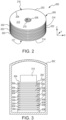
FIG. 2 illustrates a fibrous preform utilized to manufacture a carbon/carbon (C/C) disk, in accordance with various embodiments. -
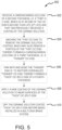
FIG. 3 illustrates a fibrous preform utilized to manufacture a carbon/carbon (C/C) disk in a carbonization furnace, in accordance with various embodiments. -
FIG. 4 illustrates a flowchart of a method for refurbishing a "thick" C/C disk coated with a ceramic solution for a second life, in accordance with various embodiments. -
FIG. 5 illustrates a flowchart of a method for refurbishing a "thin" C/C disk coated with a ceramic solution for a third life, in accordance with various embodiments. -
FIG. 6 illustrates a flowchart of a method for refurbishing a "thick" C/C split-disk coated with a ceramic solution for a fourth life, in accordance with various embodiments. - The detailed description of embodiments herein makes reference to the accompanying drawings, which show embodiments by way of illustration. While these embodiments are described in sufficient detail to enable those skilled in the art to practice the disclosure, it should be understood that other embodiments may be realized and that logical, chemical, and mechanical changes may be made without departing from the spirit and scope of the disclosure. Thus, the detailed description herein is presented for purposes of illustration only and not for limitation. For example, any reference to singular includes plural embodiments, and any reference to more than one component or step may include a singular embodiment or step. Also, any reference to attached, fixed, connected or the like may include permanent, removable, temporary, partial, full and/or any other possible attachment option. Further, any steps in a method discussed herein may be performed in any suitable order or combination.
- By itself, carbon provides good wear resistance, but the addition of ceramic particulates to the C/C brakes may decrease wear rates and increase brake life. Provided herein, in accordance with various embodiments, are methods where a carbon/carbon (C/C) disk with a ceramic solution applied may be refurbished to extend refurbished brake stack or heat sink life without a need to produce a new brake stack or heat sink. In various embodiments, a C/C disk of a first thickness, i.e. a "thick" C/C disk, which has previously received a coating of the ceramic solution and is at an end of the C/C disk's first tour life (1st life), is received. In embodiments relating to C/C disks, as used herein, a "thick" C/C disk would have a thickness of between about 0.75 inches and about 2.0 inches, although preferably a thick C/C disk would have a thickness of between about 0.75 inch and about 1.5 inches. In various embodiments, the ceramic application, which was coated onto the "thick" C/C disk previously, is removed via machining thereby forming a new "thin" C/C disk of a second thickness that is less than the first thickness of the "thick" C/C disk and with no ceramic solution applied. In various embodiments, a "thin" C/C disk would have a thickness of between about 0.75 inches and about 1.75 inches. In various embodiments, the "thin" C/C disk is then applied with a new ceramic solution coating, thus forming a refurbished C/C disk with ceramic solution coating (2nd life). In various embodiments, a ceramic solution coating may be comprised of one or more of a nano ceramic binary oxide, a doped nano ceramic binary oxide, or a nano ceramic ternary oxide particulates which is suspended in a ceramic solution known as a "sol." In various embodiments, the sol may be applied via numerous routes like spraying, painting, smearing, brushing, sorption, cold spraying, sputtering, pouring, sprinkling, peptization, or infiltration, among others, but is generally applied in small quantities at the disk surfaces as a surface coating. In various embodiments, during the operation of the brake, the nano ceramic binary oxide, doped nano ceramic binary oxide, or nano ceramic ternary oxide is mixed into the carbon wear debris as its generated which then has the ability to drastically reduce wear rates and increase brake life. In various embodiments, in response to other carbon wear debris oxidizing away, the already oxidized ceramics remain, without needing to be regenerated like current wear debris and may regenerate carbon wear debris quickly to assist in brake lubrication.
- In various embodiments, this refurbished "thin" C/C disk of the second thickness may be received for overhaul again and the sprayed on ceramic solution would be removed via machining. In various embodiments, the resulting "thinner" disk with a third thickness that is less than the second thickness may be paired with and mechanically attached to another overhauled "thinner" C/C disk to form a combined "thick" C/C split-disk of a fourth thickness that is greater than the third thickness. In various embodiments, a "thick" C/C split-disk would have a thickness of between about 1.0 inches and about 1.75 inches. In various embodiments, the combined "thick" C/C split-disk is then sprayed with a new ceramic solution coating, thus forming a refurbished combined "thick" C/C split-disk with ceramic solution coating (3rd life). In various embodiments, the refurbished combined "thick" C/C split-disk of the fourth thickness may be received for overhaul again and the sprayed on ceramic solution would be removed via machining, thereby forming a combined "thin" C/C split-disk of a fifth thickness that is less than the fourth thickness, which is sprayed with a new ceramic coating, thus forming a refurbished combined "thin" C/C split-disk (4th life). In various embodiments, a "thin" C/C split-disk would have a thickness of between about 0.8 inches and about 1.25 inches. If the refurbished combined "thin" C/C split-disk is received, the refurbished combined "thin" C/C split-disk is discarded.
- Referring to
FIG. 1 , amulti-disk brake system 20 is illustrated according to various embodiments. The system may include awheel 10 supported for rotation aroundaxle 12 bybearings 14.Axle 12 defines an axis ofmulti-disk brake system 20 and the various components thereof. Any reference to the terms axis and axial may include an axis of rotation defined byaxle 12 or a dimension parallel to such axis.Wheel 10 includesrims 16 for supporting a tire, and a series of axially extending rotor splines 18 (one shown). Rotation ofwheel 10 is modulated bymulti-disk brake system 20.Multi-disk brake system 20 includestorque flange 22,torque tube 24, a plurality of pistons 26 (one shown), pressure plate 30, andend plate 32.Torque tube 24 may be an elongated annular structure that includesreaction plate 34 and a series of axially extending stator splines 36 (one shown).Reaction plate 34 andstator splines 36 may be integral withtorque tube 24, as shown inFIG. 1 , or attached as separate components. -
Multi-disk brake system 20 also includes a plurality offriction disks 38. The plurality offriction disks 38 includes at least one non-rotatable friction disk (stator) 40, and at least one rotatable friction disk (rotor) 42.Stators 40 may include a carbon/carbon (C/C) disk.Rotors 42 may include a carbon/carbon (C/C) disk. Eachfriction disk 38 includes an attachment structure. For example,stators 40 include a plurality of stator lugs 44 at circumferentially spaced positions around an inner circumference ofstators 40, androtors 42 include a plurality of rotor lugs 46 at circumferentially spaced positions around an outer circumference ofrotors 42. -
Torque flange 22 is mounted toaxle 12.Torque tube 24 is bolted totorque flange 22 such thatreaction plate 34 is near an axial center ofwheel 10.End plate 32 is connected to a surface ofreaction plate 34 facing axially away from the axial center ofwheel 10. Thus,end plate 32 is non-rotatable by virtue of its connection totorque tube 24. Stator splines 36 may support the pressure plate 30 such that pressure plate 30 is also non-rotatable. Stator splines 36 also support thestators 40.Stators 40 engagestator splines 36 with gaps formed between stator lugs 44. Similarly,rotors 42 engagerotor splines 18 with gaps formed between rotor lugs 46. Thus,rotors 42 are rotatable by virtue of their engagement withrotor splines 18 ofwheel 10. - In various embodiments,
rotors 42 are arranged withend plate 32 on one end, pressure plate 30 on the other end, andstators 40 interleaved such thatrotors 42 are adjacent to non-rotatable friction components.Pistons 26 are connected totorque flange 22 at circumferentially spaced positions aroundtorque flange 22.Pistons 26 face axially towardwheel 10 and contact a side of pressure plate 30 oppositerotors 42.Pistons 26 may be powered electrically, hydraulically, or pneumatically. In response to actuation ofpistons 26, a force towardsreaction plate 34 is exerted onfriction disks 38 such thatrotors 42 andstators 40 are pressed together between pressure plate 30 andend plate 32. - Referring now to
FIG. 2 , in accordance with various embodiments, afibrous preform 200 utilized to manufacture a carbon/carbon (C/C) disk is illustrated.Fibrous preform 200 may be employed to form astator 40 or arotor 42, as described above.Fibrous preform 200 may comprise a porous structure comprised of a plurality of stacked textile layers 202. Eachtextile layer 202 having a thickness in a first dimension (i.e., the Z-direction) that may be substantially less than a thickness of thelayer 202 in the other two dimensions (i.e., the X-direction and the Y-direction). As used herein, the "in-plane" direction refers to directions parallel to the thicker two dimensions (i.e., parallel to the X and Y directions and perpendicular to the Z-direction). - A porous structure may comprise any structure derived from a fibrous material such as carbon fibers or the like. In various embodiments, the carbon fibers may be derived from polyacrylonitrile (PAN), rayon (synthetic fiber derived from cellulose), oxidized polyacrylonitrile fiber (OPF), pitch, or the like. The starting fiber may be pre-oxidized PAN or fully carbonized commercial carbon fiber.
Fibrous preform 200 may be prepared by needling the textile layers 202 offibrous preform 200. Needling thetextile layers 202 offibrous preform 200 tends to push fibers from onelayer 202 to thenext layer 202, thereby forming z-fibers that extend axially across thelayers 202. Needling pulls fibers from the in-plane direction and forces the fibers into the z-fiber direction. After needling,fibrous preform 200 may comprise fibers extending in three different directions: the radial direction, the circumferential direction, and the axial direction (or the X, Y, and Z directions). -
Fibrous preform 200 may be fabricated using a net shape preforming technology or may be cut from a needled board.Fibrous preform 200 may be a lay-up of woven, braided or knitted textile layers 202. The fibrous material may be in the form of chopped carbon fibers molded to form layers 202. Prior to the densification process, the fibrous material may be formed into a preform having any desired shape or form. For example, the fibrous preform may be in the form of a disk having any shape such as, for example, a polygon, a cylinder, a triangle, annular, square, rectangle, pentagon, hexagon, octagon, or the like. In various embodiments,layers 202 andfibrous preform 200 may have a generally annular shape. In accordance with various embodiments, the outer circumferential (or outer perimeter) surfaces 204 oflayers 202 may form an outer diameter (OD) 206 offibrous preform 200, and the inner circumferential (or inner perimeter) surfaces 208 oflayers 202 may form an inner diameter (ID) 210 offibrous preform 200. Eachlayer 202 includes a firstaxial face 212 and a secondaxial face 214 opposite the firstaxial face 212. First and second axial faces 212, 214 extend from outercircumferential surface 204 to innercircumferential surface 208.Layers 202 are stacked such that the firstaxial face 212 of onelayer 202 is oriented toward the secondaxial face 214 of theadjacent layer 202. Firstaxial face 212 of theuppermost layer 202 forms the upperaxial end 216 offibrous preform 200 and the secondaxial face 214 of thebottommost layer 202 forms the loweraxial end 217 of fibrous preform 200 (i.e., the twolayers 202 that are farther apart from one another in the axial direction form the axial ends 216, 217 of the fibrous preform). - As shown in
FIG. 3 , in accordance with various embodiments,fibrous preform 200 utilized to manufacture a carbon/carbon (C/C) disk being placed in acarbonization furnace 302 for carbonization is illustrated. The carbonization process may be employed to convert the fibers of thefibrous preforms 200 into pure carbon fibers, as used herein only "pure carbon fibers" means carbon fibers comprised of at least 99% carbon. The carbonization process is distinguished from the densification process described below in that the densification process involves infiltrating the pores of thefibrous preform 200 and depositing a matrix (e.g., carbon, phenolic resin, or any other desired matrix material) within and around the carbon fibers of the fibrous preform, and the carbonization process refers to the process of converting the fibers of thefibrous preform 200 into pure carbon fibers. - In various embodiments, a plurality of
fibrous preforms 200 may be placed on top of one another withseparator plates 304 and spacing stops 306 disposed between adjacentfibrous preforms 200. For example, the bottommostfibrous preform 200 may be placed on abase plate 308 at the bottom ofcarbonization furnace 302. Aseparator plate 304 may be placed on top of the bottommostfibrous preform 200. Anotherfibrous preform 200 may then be placed on theseparator plate 304, and anotherseparator plate 304 may be placed on thatfibrous preform 200. A stack offibrous preforms 200 andseparator plates 304 may be constructed in this manner, with eachfibrous preform 200 being separated from superjacent and subjacentfibrous preforms 200 byseparator plates 304. Spacing stops 306 may be placed between each of theseparator plates 304. The spacing stops 306 may comprise a height that is less than the thickness of thefibrous preform 200 prior to carbonization. Spacing stops 306 may define a target thickness of thefibrous preform 200 after carbonization. In that regard, after the stack offibrous preforms 200 is constructed, and before the carbonization process has started, gaps may exist between the spacing stops 306 andadjacent separator plates 304. During carbonization, a compressive load may be applied to thefibrous preforms 200, thereby compressing thefibrous preforms 200 until spacing stops 306 contactadjacent separator plates 304. - In various embodiments, compressive pressure may be applied to
fibrous preforms 200 during the carbonization. The compressive pressure may be applied by placing aweight 310 overfibrous preforms 200, or by applying a compressive load to thefibrous preforms 200 by other suitable means. The compressive pressure may be applied along the direction of the z-fibers. It will be appreciated by those skilled in the art that the mass ofweight 310 and/or the compressive force generated byweight 310 may vary depending on the size offibrous preforms 200, the pre-carbonization fiber volume offibrous preforms 200, the desired post-carbonization fiber volume offibrous preforms 200, and/or the number fibrous preforms 200 being compressed. As used herein, "fiber volume" refers the percentage of the total volume of the fibrous preform that is formed by the fibers of the fibrous preform. For example, a fiber volume of 18% means the fibers of thefibrous preform form 18% of the total volume of fibrous preform. In various embodiments, after carbonization,fibrous preform 200 includes a fiber volume of between 10% and 50%. In various embodiments, after carbonization,fibrous preform 200 includes a fiber volume of between 15% and 25%. In various embodiments,fibrous preforms 200 having a low fiber volume may be desirable for the infiltration methods disclosed herein. In various embodiments, after carbonization,fibrous preform 200 may comprise a fiber volume of less than 25%. For example, in various embodiments, after carbonization,fibrous preform 200 may comprise a fiber volume of 21% or, in various embodiments,fibrous preform 200 may comprise a fiber volume of 18%. In various embodiments, the carbonizedfibrous preform 200 is then densified via chemical vapor infiltration (CVI) with pyrolytic carbon at a predetermined temperature for a predetermined time interval as is known in the art, which results in a finished C/C disk. - Referring now to
FIG. 4 , in accordance with various embodiments, a flowchart of amethod 400 for refurbishing a "thick" C/C disk coated with a ceramic solution applied to its wear surfaces for a second life is illustrated. In various embodiments, atblock 402, a carbon/carbon (C/C) disk of a first thickness, i.e. a "thick" C/C disk, which is at an end of the C/C disk's first tour life (1st life) and that has previously received a coating of the ceramic solution to its wear surfaces, is received. In various embodiments, atblock 404, the "thick" C/C disk is machined to remove the ceramic solution coating from the wear surfaces, which may also remove a portion of the "thick" C/C disk, thereby forming a carbon/carbon (C/C) disk of a second thickness, i.e. a "thin" C/C disk, where the second thickness is less than the first thickness. In various embodiments, at block 406 a new coating of the ceramic solution, i.e. nano ceramic binary oxide, doped nano ceramic binary oxide, or nano ceramic ternary oxide particulates suspended in a ceramic solution, referred to as a "sol," is applied to the wear surfaces of the "thin" C/C disk. In various embodiments, the particulates have an average particle size of between 10 nanometers (0.3937 microinch) and 250 nanometers (9.843 microinches). In various embodiments, the particulates have an average particle size of between 10 nanometers (0.3937 microinch) and 150 nanometers (5.906 microinches). In various embodiments, the particulates have an average particle size of between 10 nanometers (0.3937 microinch) and 50 nanometers (1.969 microinches). In various embodiments, the sol may be applied via numerous routes such as spraying, painting, smearing, brushing, sorption, cold spraying, sputtering, pouring, sprinkling, peptization, or infiltration, among others to physically coat the wear surface of the C/C disk. In various embodiments, the sol may be applied in small quantities at the disk wear surfaces like a surface coating. In that regard, in various embodiments, an amount of sol applied may be between .025 cubic centimeters (0.001526 cubic inches) and 3 cubic centimeters (0.1831 cubic inches) per unit of disk surface. In various embodiments, an amount of sol applied may be between .075 cubic centimeters (0.004577 cubic inches) and 2.5 cubic centimeters (0.1526 cubic inches) per disk surface. In that regard, in various embodiments, an amount of sol applied may be between .125 cubic centimeters (0.007628 cubic inches) and 2 cubic centimeters (0.122 cubic inches) per disk surface. In various embodiments, during the operation of the brake, the nano ceramic binary oxide, doped nano ceramic binary oxide, or nano ceramic ternary oxide is mixed into the carbon wear debris as its generated which then has the ability to drastically reduce wear rates and increase brake life. In various embodiments, in response to other carbon wear debris oxidizing away, the already oxidized ceramics remain, without needed to be regenerated like current wear debris coatings. - In various embodiments, the nano ceramic binary oxide particulates may include zirconium oxide (ZrO2), aluminum oxide (Al2O3), or magnesium oxide (MgO), and various combinations of the same, among others. In various embodiments, the nano ceramic binary oxide particulates may include lithium oxide (Li2O), beryllium oxide (BeO), calcium oxide (CaO), strontium oxide (SrO), or barium oxide (BaO), and various combinations of the same, among others. In various embodiments, the nano ceramic binary oxide particulates may include scandium(III) oxide (Sc2O3), yttrium oxide (Y2O3), cobalt(II) oxide (CoO), or nickel oxide (NiO), and various combinations of the same, among others. In various embodiments, the nano ceramic binary oxide particulates may include silicon oxide (SiO2), titanium oxide (TiO2), or hafnium(IV) oxide (HfO2), and various combinations of the same, among others. In various embodiments, the nano ceramic binary oxide particulates may include vanadium(II) oxide (VO), vanadium(III) oxide (V2O3), vanadium oxide (VO2), niobium(II) oxide (NbO), tantalum oxide (Ta2O5), tungsten(IV) oxide (WO2), or tungsten trioxide (WO3), and various combinations of the same, among others. In various embodiments, the nano ceramic binary oxide particulates may include gallium oxide (GaO), indium oxide (In2O3), or tin(IV) oxide (SnO2), and various combinations of the same, among others. In various embodiments, the nano ceramic binary oxide particulates may include lanthanum oxide (La2O3), cerium oxide (CeO2), praseodymium(III,IV) oxide (Pr6O11), or neodymium oxide (Nd2O3), and various combinations of the same, among others. In various embodiments, the nano ceramic binary oxide particulates may include samarium oxide (Sm2O3), europium oxide (Eu2O3), gadolinium oxide (Gd2O3), terbium oxide (Tb2O3), or dysprosium oxide (Dy2O3), and various combinations of the same, among others. In various embodiments, the nano ceramic binary oxide particulates may include holmium oxide (Ho2O3), erbium oxide (Er2O3), thulium oxide (Tm2O3), ytterbium oxide (Yb2O3), or lutetium oxide (Lu2O3), and various combinations of the same, among others. In various embodiments, the doped nano ceramic binary oxide particulates may include yttrium oxide-stabilized zirconium(IV) oxide (YSZ) or zirconium(IV) oxide toughened aluminum oxide (ZTA), and various combinations of the same, among others. In various embodiments, the nano ceramic ternary oxide particulates may include lithium silicate (Li2SiO3), mullite (Si2Al6O13), calcium silicate (Ca2SiO4), or hafnium orthosilicate (HfSiO4), and various combinations of the same, among others. In various embodiments, the nano ceramic ternary oxide particulates may include lithium titanate (Li2TiO3), aluminum titanate (Al2TiO5), calcium titanate (CaTiO3), strontium titanate (SrTiO3), barium titanate (BaTiO3), or hafnium titanate (HfTiO4), and various combinations of the same, among others. In various embodiments, the nano ceramic ternary oxide particulates may include strontium zirconate (SrZrO3) or barium zirconate (BaZrO3), and various combinations of the same, among others. In various embodiments, at
block 408, the ceramic solution coated "thin" C/C disk may then be dried before being installed in a multi-disk brake system, such as the multi-disk brake mechanism 100 ofFIG. 1 , thereby starting its second life. - Referring now to
FIG. 5 , in accordance with various embodiments, a flowchart of amethod 500 for refurbishing a "thin" C/C disk coated with a ceramic solution applied to its wear surfaces for a third life is illustrated. In various embodiments, atblock 502, a carbon/carbon (C/C) disk of a second thickness, i.e. a "thin" C/C disk, which is at an end of the C/C disk's second tour life (2nd life) and that has previously received a coating of the ceramic solution to its wear surfaces, is received. In various embodiments, atblock 504, the "thin" C/C disk is machined to remove the ceramic solution coating from the wear surfaces, which may also remove a portion of the "thin" C/C disk, thereby forming a carbon/carbon (C/C) disk of a third thickness, i.e. a "thinner" C/C disk, where the third thickness is less than the second thickness. In various embodiments, atblock 506, the "thinner" disk is pair with and mechanically attached to another overhauled "thinner" C/C disk thereby forming a "thick" C/C split-disk of a fourth thickness that is greater than the third thickness. In various embodiments, at block 508 a new coating of the ceramic solution, i.e. the ceramic solution described previously with regard toFIG. 4 , is applied to wear surfaces of the "thick" C/C split-disk. In various embodiments, atblock 510, the ceramic solution coated "thick" C/C split-disk may then be dried before being installed in a multi-disk brake system, such as the multi-disk brake mechanism 100 ofFIG. 1 thereby starting its third life. - Referring now to
FIG. 6 , in accordance with various embodiments, a flowchart of amethod 600 for refurbishing a "thick" C/C split-disk coated with a ceramic solution applied to its wear surfaces for a fourth life is illustrated. In various embodiments, atblock 602, a carbon/carbon (C/C) disk of a fourth thickness, i.e. a "thick" C/C split-disk, which is at an end of the C/C disk's third tour life (3rd life) and that has previously received a coating of the ceramic solution to its wear surfaces, is received. In various embodiments, atblock 604, the "thick" C/C split-disk is machined to remove the ceramic solution coating from the wear surfaces, which may also remove a portion of the "thick" C/C split-disk, thereby forming a carbon/carbon (C/C) disk of a fifth thickness, i.e. a "thin" C/C split-disk, where the fifth thickness is less than the fourth thickness. In various embodiments, at block 606 a new coating of the ceramic solution, i.e. the ceramic solution described previously with regard toFIG. 4 , is applied to wear surfaces of the "thin" C/C split-disk. In various embodiments, atblock 608, the ceramic solution coated "thin" C/C split-disk may then be dried before being installed in a multi-disk brake system, such as the multi-disk brake mechanism 100 ofFIG. 1 thereby starting its fourth life. - Benefits and other advantages have been described herein with regard to specific embodiments. Furthermore, the connecting lines shown in the various figures contained herein are intended to represent exemplary functional relationships and/or physical couplings between the various elements. It should be noted that many alternative or additional functional relationships or physical connections may be present in a practical system. However, the benefits, advantages, solutions to problems, and any elements that may cause any benefit, advantage, or solution to occur or become more pronounced are not to be construed as critical, required, or essential features or elements of the disclosure. The scope of the disclosure is accordingly to be limited by nothing other than the appended claims, in which reference to an element in the singular is not intended to mean "one and only one" unless explicitly so stated, but rather "one or more." Moreover, where a phrase similar to "at least one of A, B, or C" is used in the claims, it is intended that the phrase be interpreted to mean that A alone may be present in an embodiment, B alone may be present in an embodiment, C alone may be present in an embodiment, or that any combination of the elements A, B and C may be present in a single embodiment; for example, A and B, A and C, B and C, or A and B and C.
- Systems, methods, and apparatus are provided herein. In the detailed description herein, references to "one embodiment," "an embodiment," "an example embodiment," etc., indicate that the embodiment described may include a particular feature, structure, or characteristic, but every embodiment may not necessarily include the particular feature, structure, or characteristic. Moreover, such phrases are not necessarily referring to the same embodiment. Further, when a particular feature, structure, or characteristic is described in connection with an embodiment, it is submitted that it is within the knowledge of one skilled in the art to affect such feature, structure, or characteristic in connection with other embodiments whether or not explicitly described. After reading the description, it will be apparent to one skilled in the relevant art(s) how to implement the disclosure in alternative embodiments.
- Furthermore, no element, component, or method step in the present disclosure is intended to be dedicated to the public regardless of whether the element, component, or method step is explicitly recited in the claims. As used herein, the terms "comprises," "comprising," or any other variation thereof, are intended to cover a non-exclusive inclusion, such that a process, method, article, or apparatus that comprises a list of elements does not include only those elements but may include other elements not expressly listed or inherent to such process, method, article, or apparatus.
Claims (15)
- A method for refurbishing a C/C disk of a first thickness and coated with a first ceramic solution for a second life, comprising:machining (402, 502, 604) the C/C disk of the first thickness to remove a coating of the first ceramic solution from the wear surfaces of the C/C disk of the first thickness thereby forming a C/C disk of a second thickness and wherein the second thickness is less than the first thickness;coating (406, 508, 606) the wear surfaces of the C/C disk of the second thickness with a second ceramic solution, thereby forming a C/C disk of the second thickness coated with the second ceramic solution; anddrying (408, 510, 608) the C/C disk of the second thickness coated with the second ceramic solution.
- The method of claim 1,wherein removing the coating of the first ceramic solution from the wear surfaces of the C/C disk of the first thickness further removes a portion of the C/C disk; andwherein the second ceramic solution is applied to a wear surface of the C/C disk of the second thickness via at least one of spraying, painting, smearing, brushing, sorption, cold spraying, sputtering, pouring, sprinkling, peptization, or infiltration.
- The method of claim 1, wherein the second ceramic solution comprises at least one of nano ceramic binary oxide particulates, doped nano ceramic binary oxide particulates, or nano ceramic ternary oxide particulates.
- The method of claim 3, wherein the nano ceramic binary oxide particulates comprise at least one of zirconium dioxide (ZrO2), aluminum oxide (Al2O3), or magnesium oxide (MgO), or
wherein the nano ceramic binary oxide particulates comprise at least one of lithium oxide (Li2O), beryllium oxide (BeO), calcium oxide (CaO), strontium oxide (SrO), or barium oxide (BaO). - The method of claim 3, wherein the nano ceramic binary oxide particulates comprise at least one of scandium(III) oxide (Sc2O3), yttrium oxide (Y2O3), cobalt(II) oxide (CoO), or nickel oxide (NiO), or wherein the nano ceramic binary oxide particulates comprise at least one of silicon oxide (SiO2), titanium oxide (TiO2), zirconium oxide (ZrO2), or hafnium(IV) oxide (HfO2).
- The method of claim 3, wherein the nano ceramic binary oxide particulates comprise at least one of vanadium(II) oxide (VO), vanadium(III) oxide (V2O3), vanadium oxide (VO2), niobium(II) oxide (NbO), tantalum oxide (Ta2O5), tungsten(IV) oxide (WO2), or tungsten trioxide (WO3), or wherein the nano ceramic binary oxide particulates comprise at least one of, gallium oxide (GaO), indium oxide (In2O3), or tin(IV) oxide (SnO2).
- The method of claim 3, wherein the nano ceramic binary oxide particulates comprise at least one of lanthanum oxide (La2O3), cerium dioxide (CeO2), praseodymium(III,IV) oxide (Pr6O11), or neodymium oxide (Nd2O3, or
wherein the nano ceramic binary oxide particulates comprise at least one of samarium oxide (Sm2O3), europium oxide (Eu2O3), gadolinium oxide (Gd2O3), terbium oxide (Tb2O3), or dysprosium oxide (Dy2O3). - The method of claim 3, wherein the nano ceramic binary oxide particulates comprise at least one of holmium oxide (Ho2O3), erbium oxide (Er2O3), thulium oxide (Tm2O3), ytterbium oxide (Yb2O3), or lutetium oxide (Lu2O3).
- The method of claim 3, wherein the doped nano ceramic binary oxide particulates comprise at least one of yttrium oxide stabilized zirconium(IV) oxide (YSZ) or zirconium(IV) oxide toughened aluminum oxide (ZTA).
- The method of claim 3, wherein the nano ceramic ternary oxide particulates comprise at least one of lithium silicate (Li2SiO3), mullite (Si2Al6O13), calcium silicate (Ca2SiO4), or hafnium orthosilicate (HfSiO4), or wherein the nano ceramic ternary oxide particulates comprise at least one of lithium titanate (Li2TiO3), aluminum titanate (Al2TiO5), calcium titanate (CaTiO3), strontium titanate (SrTiO3), barium titanate (BaTiO3), or hafnium titanate (HfTiO4).
- The method of claim 3, wherein the nano ceramic ternary oxide particulates comprise at least one of strontium zirconate (SrZrO3) or barium zirconate (BaZrO3).
- A method for refurbishing a C/C disk of a second thickness and coated with a second ceramic solution for a third life, comprising:machining the C/C disk of the second thickness to remove a coating of the second ceramic solution from the wear surfaces of the C/C disk of the second thickness thereby forming a C/C disk of a third thickness and wherein the third thickness is less than the second thickness;pairing with and mechanically attaching the C/C disk of the third thickness with another C/C disk of the third thickness thereby forming a C/C split-disk of a fourth thickness, wherein the fourth thickness is greater than the third thickness;coating the wear surfaces of the C/C split-disk of the fourth thickness with a third ceramic solution, thereby forming a C/C split-disk of the fourth thickness coated with the third ceramic solution; anddrying the C/C split-disk of the fourth thickness coated with the third ceramic solution.
- The method of claim 12,wherein removing the coating of the second ceramic solution from the wear surfaces of the C/C disk of the second thickness further removes a portion of the C/C disk,wherein the third ceramic solution is applied to a wear surface of the C/C split-disk of the fourth thickness via at least one of spraying, painting, smearing, brushing, sorption, cold spraying, sputtering, pouring, sprinkling, peptization, or infiltration, andwherein the third ceramic solution comprises at least one of nano ceramic binary oxide particulates, doped nano ceramic binary oxide particulates, or nano ceramic ternary oxide particulates.
- A method for refurbishing a C/C split-disk of a fourth thickness and coated with a third ceramic solution for a fourth life, comprising:machining the C/C split-disk of the fourth thickness to remove a coating of the third ceramic solution from the wear surfaces of the C/C split-disk of the fourth thickness thereby forming a C/C split-disk of a fifth thickness and wherein the fifth thickness is less than the fourth thickness;coating the wear surfaces of the C/C split-disk of the fifth thickness with a fourth ceramic solution, thereby forming a C/C split-disk of the fifth thickness coated with the fourth ceramic solution; anddrying the C/C split-disk of the fifth thickness coated with the fourth ceramic solution.
- The method of claim 14,wherein removing the coating of the third ceramic solution from the wear surfaces of the C/C split-disk of the fourth thickness further removes a portion of the C/C split-disk,wherein the fourth ceramic solution is applied to a wear surface of the C/C split-disk of the fifth thickness via at least one of spraying, painting, smearing, brushing, sorption, cold spraying, sputtering, pouring, sprinkling, peptization, or infiltration, andwherein the fourth ceramic solution comprises at least one of nano ceramic binary oxide particulates, doped nano ceramic binary oxide particulates, or nano ceramic ternary oxide particulates.
Applications Claiming Priority (1)
| Application Number | Priority Date | Filing Date | Title |
|---|---|---|---|
| US18/474,607 US12577998B2 (en) | 2023-09-26 | 2023-09-26 | Material life extension for refurbished 2-for-1 carbon brakes via ceramic solutions |
Publications (1)
| Publication Number | Publication Date |
|---|---|
| EP4582716A1 true EP4582716A1 (en) | 2025-07-09 |
Family
ID=92895766
Family Applications (1)
| Application Number | Title | Priority Date | Filing Date |
|---|---|---|---|
| EP24202053.5A Pending EP4582716A1 (en) | 2023-09-26 | 2024-09-23 | Material life extension for refurbished 2-for-1 carbon brakes via ceramic solutions |
Country Status (2)
| Country | Link |
|---|---|
| US (1) | US12577998B2 (en) |
| EP (1) | EP4582716A1 (en) |
Citations (1)
| Publication number | Priority date | Publication date | Assignee | Title |
|---|---|---|---|---|
| CN113045324A (en) * | 2021-03-28 | 2021-06-29 | 西北工业大学 | Method for repairing and recycling C/C-SiC brake disc worn to end |
Family Cites Families (42)
| Publication number | Priority date | Publication date | Assignee | Title |
|---|---|---|---|---|
| US3871934A (en) | 1973-06-28 | 1975-03-18 | Carborundum Co | Resurfacing brake discs |
| CH633868A5 (en) | 1977-09-07 | 1982-12-31 | Alusuisse | WEAR-RESISTANT COATING OF THE WORK SURFACE OF DISC-SHAPED MACHINE PARTS MADE OF ALUMINUM OR ALUMINUM ALLOYS. |
| US5224572A (en) | 1991-07-29 | 1993-07-06 | Smolen Jr George W | Lightweight brake rotor with a thin, heat resistant ceramic coating |
| JP3160688B2 (en) | 1993-08-02 | 2001-04-25 | キヤノン株式会社 | Non-magnetic one-component developer |
| FR2717874B1 (en) | 1994-03-25 | 1996-04-26 | Gec Alsthom Transport Sa | Multimaterial disc for high energy braking. |
| US5962135A (en) | 1997-04-09 | 1999-10-05 | Alliedsignal Inc. | Carbon/carbon friction material |
| DE19859839A1 (en) | 1998-12-23 | 2000-07-06 | Daimler Chrysler Ag | Brake unit |
| US6969546B2 (en) | 2003-10-20 | 2005-11-29 | The Boeing Company | Thermal insulation system employing oxide ceramic matrix composites |
| CA2504831C (en) | 2005-04-21 | 2010-10-19 | Standard Aero Limited | Wear resistant ceramic composite coatings and process for production thereof |
| GB2426756A (en) | 2005-06-03 | 2006-12-06 | Huntercombe Consultancy Ltd | Porous body containing within its pores a chemically bonded phosphate ceramic |
| US7900751B2 (en) * | 2006-02-01 | 2011-03-08 | Honeywell International Inc. | Method and brake disc assembly to utilize worn refurbished brake material |
| US7501181B2 (en) | 2006-03-17 | 2009-03-10 | Honeywell International Inc. | Bi-or tri-layer anti-oxidation system for carbon composite brakes |
| EP1845075B1 (en) | 2006-04-11 | 2016-04-06 | SGL Carbon SE | Carbon fibre reinforced carbon bodies and a method for their production |
| GB0625488D0 (en) | 2006-12-20 | 2007-01-31 | Hunterscombe Consultancy Ltd | Method for forming a carbon-containing material |
| EP2122004B1 (en) | 2007-02-20 | 2013-01-30 | Tech M3, Inc. | Wear resistant coating for brake disks with unique surface appearance and methods for coating |
| US8449943B2 (en) | 2007-02-20 | 2013-05-28 | Tech M3, Inc. | Composite brake disks and methods for coating |
| DE102008019495B4 (en) | 2008-04-17 | 2010-05-12 | Eads Deutschland Gmbh | A method of improving the oxidation resistance of a porous carbonaceous substrate, a method of making an infiltrating material, and an oxidation resistant substrate |
| FR2945529B1 (en) | 2009-05-13 | 2011-06-17 | Messier Bugatti | PIECE BASED ON COMPOSITE C / C MATERIAL AND METHOD FOR MANUFACTURING THE SAME |
| JP5678332B2 (en) | 2009-09-04 | 2015-03-04 | 東洋炭素株式会社 | Ceramic carbon composite material and manufacturing method thereof, ceramic-coated ceramic carbon composite material and manufacturing method thereof |
| FR2958933B1 (en) | 2010-04-20 | 2015-08-07 | Onera (Off Nat Aerospatiale) | PROCESS FOR PRODUCING A CERAMIC MATRIX COMPOSITE PIECE |
| JP5051286B2 (en) | 2010-08-31 | 2012-10-17 | 曙機械工業株式会社 | Blade type used for die cutting and die cutting method using the blade die |
| FR2967170B1 (en) | 2010-11-10 | 2013-09-20 | Messier Bugatti | PROCESS FOR MANUFACTURING A FRICTION PIECE BASED ON COMPOSITE C / C MATERIAL |
| GB2485673B (en) | 2010-11-17 | 2017-11-15 | Meggitt Aerospace Ltd | Brake disc |
| KR101375139B1 (en) * | 2012-08-27 | 2014-03-17 | 주식회사 데크 | Method for refurbishing aircraft disk |
| US9631916B2 (en) | 2013-03-13 | 2017-04-25 | Rolls Royce Corporation | Component including structures for determinant loading |
| JP6125592B2 (en) | 2015-10-08 | 2017-05-10 | 日清紡ブレーキ株式会社 | Friction material |
| US10000425B2 (en) | 2016-03-21 | 2018-06-19 | Goodrich Corporation | Systems and methods for carbon structures incorporating silicon carbide whiskers |
| US10767059B2 (en) | 2016-08-11 | 2020-09-08 | Goodrich Corporation | High temperature oxidation protection for composites |
| FR3071257B1 (en) | 2017-09-19 | 2021-08-20 | Safran Ceram | PROCESS FOR INJECTING A SUSPENSION LOADED IN A FIBROUS TEXTURE AND PROCESS FOR MANUFACTURING A PART FROM COMPOSITE MATERIAL |
| US10450236B2 (en) | 2017-09-25 | 2019-10-22 | Goodrich Corporation | Carbon/carbon composites and methods of making carbon/carbon composites having increased fiber volume and ceramic compounds |
| CN109384470B (en) | 2018-11-08 | 2021-06-22 | 中南大学 | Rapid preparation method of C/C composite material |
| US11634213B2 (en) | 2018-11-14 | 2023-04-25 | Goodrich Corporation | High temperature oxidation protection for composites |
| US20200200227A1 (en) | 2018-12-19 | 2020-06-25 | Goodrich Corporation | Aircraft brake heatsink wear liner |
| CN110305504B (en) | 2019-06-28 | 2020-10-09 | 江南大学 | A kind of hybrid carbon nanotube reinforced wear-resistant and anti-friction ceramic coating and preparation method |
| US11649191B2 (en) | 2019-10-08 | 2023-05-16 | Goodrich Corporation | Fabrication of high heat capacity ceramic matrix composite aircraft brakes using spark plasma sintering |
| CN110937910B (en) | 2019-12-13 | 2021-09-07 | 中南大学 | A kind of preparation method of composite nanometer refractory ceramic modified carbon/carbon composite material |
| CN110981518B (en) | 2019-12-17 | 2021-01-01 | 湖南金博碳素股份有限公司 | Carbon-ceramic composite material brake disc and preparation method thereof |
| CN113277869B (en) | 2021-05-26 | 2023-03-31 | 湖南世鑫新材料有限公司 | Carbon-ceramic brake disc with wear-resistant and oxidation-resistant coating and preparation method thereof |
| US12065380B2 (en) | 2021-11-16 | 2024-08-20 | Goodrich Corporation | High temperature oxidation protection for carbon-carbon composites |
| US12522543B2 (en) | 2022-02-02 | 2026-01-13 | Goodrich Corporation | Methods of forming siAlON in carbon/carbon composites |
| CN115385711B (en) | 2022-07-05 | 2024-09-17 | 烟台凯泊复合材料科技有限公司 | Composite structure light ceramic brake disc and preparation method thereof |
| CN115773321B (en) | 2023-02-13 | 2023-05-09 | 西安超码科技有限公司 | High-strength carbon/ceramic brake disc with ceramic functional layer |
-
2023
- 2023-09-26 US US18/474,607 patent/US12577998B2/en active Active
-
2024
- 2024-09-23 EP EP24202053.5A patent/EP4582716A1/en active Pending
Patent Citations (1)
| Publication number | Priority date | Publication date | Assignee | Title |
|---|---|---|---|---|
| CN113045324A (en) * | 2021-03-28 | 2021-06-29 | 西北工业大学 | Method for repairing and recycling C/C-SiC brake disc worn to end |
Also Published As
| Publication number | Publication date |
|---|---|
| US20250102032A1 (en) | 2025-03-27 |
| US12577998B2 (en) | 2026-03-17 |
Similar Documents
| Publication | Publication Date | Title |
|---|---|---|
| US10450236B2 (en) | Carbon/carbon composites and methods of making carbon/carbon composites having increased fiber volume and ceramic compounds | |
| US12447715B2 (en) | Composites and methods of forming composites having an increased volume of ceramic particles | |
| EP4272956A2 (en) | Z-direction reinforced composites and methods of forming z-direction reinforced composites | |
| US12146539B2 (en) | Composites and methods of forming composites having friction and wear plugs | |
| EP3816137A1 (en) | Method of manufacturing cmc components using boron carbide | |
| US12522543B2 (en) | Methods of forming siAlON in carbon/carbon composites | |
| EP4520743A1 (en) | Ceramic particulate coating for wear improvement | |
| US12577998B2 (en) | Material life extension for refurbished 2-for-1 carbon brakes via ceramic solutions | |
| EP3569400B1 (en) | Carbon nanotube based heat shield | |
| EP4538253A1 (en) | Ceramic modification of c/c brakes within a furnace run | |
| CN115385711A (en) | Composite-structure light ceramic brake disc and preparation method thereof | |
| EP4549415A2 (en) | Ceramic infiltration of aircraft brakes via injection for wear improvement | |
| EP4321335A2 (en) | Method to limit silicon in b4c particulate based cmc composites | |
| EP4542078A1 (en) | Ceramic modified liners for wear improvement incore-liner brake configuration | |
| EP4282847A1 (en) | Sacrificial materials to improve chemical vapor infiltration of b4c loaded preforms | |
| EP4556741A1 (en) | Coating of a carbon/carbon (c/c) disk providing oxidation protection and wear improvement | |
| US12515997B2 (en) | Infiltrating boron nitride into a carbon-carbon substrate | |
| US12552720B2 (en) | Methods and systems for in-plane slurry infiltration of composite preforms | |
| EP4635932A1 (en) | Chemical vapor deposition (cvd) after heatreatment for improved silicon melt infiltration processing | |
| US20260132088A1 (en) | Method to limit silicon in b4c particulate based cmc composites | |
| EP4488246A1 (en) | Low cost, low wear preform | |
| EP3878829A2 (en) | Composites and methods of forming composites via pitch infiltration |
Legal Events
| Date | Code | Title | Description |
|---|---|---|---|
| PUAI | Public reference made under article 153(3) epc to a published international application that has entered the european phase |
Free format text: ORIGINAL CODE: 0009012 |
|
| STAA | Information on the status of an ep patent application or granted ep patent |
Free format text: STATUS: THE APPLICATION HAS BEEN PUBLISHED |
|
| AK | Designated contracting states |
Kind code of ref document: A1 Designated state(s): AL AT BE BG CH CY CZ DE DK EE ES FI FR GB GR HR HU IE IS IT LI LT LU LV MC ME MK MT NL NO PL PT RO RS SE SI SK SM TR |
|
| STAA | Information on the status of an ep patent application or granted ep patent |
Free format text: STATUS: REQUEST FOR EXAMINATION WAS MADE |
|
| 17P | Request for examination filed |
Effective date: 20260108 |