EP4582714A1 - Sealing structure - Google Patents
Sealing structure Download PDFInfo
- Publication number
- EP4582714A1 EP4582714A1 EP23860314.6A EP23860314A EP4582714A1 EP 4582714 A1 EP4582714 A1 EP 4582714A1 EP 23860314 A EP23860314 A EP 23860314A EP 4582714 A1 EP4582714 A1 EP 4582714A1
- Authority
- EP
- European Patent Office
- Prior art keywords
- peripheral side
- side member
- lip
- outer peripheral
- sealing structure
- Prior art date
- Legal status (The legal status is an assumption and is not a legal conclusion. Google has not performed a legal analysis and makes no representation as to the accuracy of the status listed.)
- Pending
Links
Images



Classifications
-
- F—MECHANICAL ENGINEERING; LIGHTING; HEATING; WEAPONS; BLASTING
- F16—ENGINEERING ELEMENTS AND UNITS; GENERAL MEASURES FOR PRODUCING AND MAINTAINING EFFECTIVE FUNCTIONING OF MACHINES OR INSTALLATIONS; THERMAL INSULATION IN GENERAL
- F16J—PISTONS; CYLINDERS; SEALINGS
- F16J15/00—Sealings
- F16J15/16—Sealings between relatively-moving surfaces
- F16J15/32—Sealings between relatively-moving surfaces with elastic sealings, e.g. O-rings
- F16J15/3204—Sealings between relatively-moving surfaces with elastic sealings, e.g. O-rings with at least one lip
- F16J15/3232—Sealings between relatively-moving surfaces with elastic sealings, e.g. O-rings with at least one lip having two or more lips
- F16J15/3236—Sealings between relatively-moving surfaces with elastic sealings, e.g. O-rings with at least one lip having two or more lips with at least one lip for each surface, e.g. U-cup packings
-
- F—MECHANICAL ENGINEERING; LIGHTING; HEATING; WEAPONS; BLASTING
- F16—ENGINEERING ELEMENTS AND UNITS; GENERAL MEASURES FOR PRODUCING AND MAINTAINING EFFECTIVE FUNCTIONING OF MACHINES OR INSTALLATIONS; THERMAL INSULATION IN GENERAL
- F16C—SHAFTS; FLEXIBLE SHAFTS; ELEMENTS OR CRANKSHAFT MECHANISMS; ROTARY BODIES OTHER THAN GEARING ELEMENTS; BEARINGS
- F16C19/00—Bearings with rolling contact, for exclusively rotary movement
- F16C19/02—Bearings with rolling contact, for exclusively rotary movement with bearing balls essentially of the same size in one or more circular rows
- F16C19/14—Bearings with rolling contact, for exclusively rotary movement with bearing balls essentially of the same size in one or more circular rows for both radial and axial load
- F16C19/18—Bearings with rolling contact, for exclusively rotary movement with bearing balls essentially of the same size in one or more circular rows for both radial and axial load with two or more rows of balls
-
- F—MECHANICAL ENGINEERING; LIGHTING; HEATING; WEAPONS; BLASTING
- F16—ENGINEERING ELEMENTS AND UNITS; GENERAL MEASURES FOR PRODUCING AND MAINTAINING EFFECTIVE FUNCTIONING OF MACHINES OR INSTALLATIONS; THERMAL INSULATION IN GENERAL
- F16C—SHAFTS; FLEXIBLE SHAFTS; ELEMENTS OR CRANKSHAFT MECHANISMS; ROTARY BODIES OTHER THAN GEARING ELEMENTS; BEARINGS
- F16C33/00—Parts of bearings; Special methods for making bearings or parts thereof
- F16C33/72—Sealings
- F16C33/76—Sealings of ball or roller bearings
- F16C33/78—Sealings of ball or roller bearings with a diaphragm, disc, or ring, with or without resilient members
- F16C33/7816—Details of the sealing or parts thereof, e.g. geometry, material
-
- F—MECHANICAL ENGINEERING; LIGHTING; HEATING; WEAPONS; BLASTING
- F16—ENGINEERING ELEMENTS AND UNITS; GENERAL MEASURES FOR PRODUCING AND MAINTAINING EFFECTIVE FUNCTIONING OF MACHINES OR INSTALLATIONS; THERMAL INSULATION IN GENERAL
- F16C—SHAFTS; FLEXIBLE SHAFTS; ELEMENTS OR CRANKSHAFT MECHANISMS; ROTARY BODIES OTHER THAN GEARING ELEMENTS; BEARINGS
- F16C33/00—Parts of bearings; Special methods for making bearings or parts thereof
- F16C33/72—Sealings
- F16C33/76—Sealings of ball or roller bearings
- F16C33/78—Sealings of ball or roller bearings with a diaphragm, disc, or ring, with or without resilient members
- F16C33/7869—Sealings of ball or roller bearings with a diaphragm, disc, or ring, with or without resilient members mounted with a cylindrical portion to the inner surface of the outer race and having a radial portion extending inward
-
- F—MECHANICAL ENGINEERING; LIGHTING; HEATING; WEAPONS; BLASTING
- F16—ENGINEERING ELEMENTS AND UNITS; GENERAL MEASURES FOR PRODUCING AND MAINTAINING EFFECTIVE FUNCTIONING OF MACHINES OR INSTALLATIONS; THERMAL INSULATION IN GENERAL
- F16C—SHAFTS; FLEXIBLE SHAFTS; ELEMENTS OR CRANKSHAFT MECHANISMS; ROTARY BODIES OTHER THAN GEARING ELEMENTS; BEARINGS
- F16C33/00—Parts of bearings; Special methods for making bearings or parts thereof
- F16C33/72—Sealings
- F16C33/76—Sealings of ball or roller bearings
- F16C33/78—Sealings of ball or roller bearings with a diaphragm, disc, or ring, with or without resilient members
- F16C33/7886—Sealings of ball or roller bearings with a diaphragm, disc, or ring, with or without resilient members mounted outside the gap between the inner and outer races, e.g. sealing rings mounted to an end face or outer surface of a race
-
- F—MECHANICAL ENGINEERING; LIGHTING; HEATING; WEAPONS; BLASTING
- F16—ENGINEERING ELEMENTS AND UNITS; GENERAL MEASURES FOR PRODUCING AND MAINTAINING EFFECTIVE FUNCTIONING OF MACHINES OR INSTALLATIONS; THERMAL INSULATION IN GENERAL
- F16J—PISTONS; CYLINDERS; SEALINGS
- F16J15/00—Sealings
- F16J15/16—Sealings between relatively-moving surfaces
- F16J15/164—Sealings between relatively-moving surfaces the sealing action depending on movements; pressure difference, temperature or presence of leaking fluid
-
- F—MECHANICAL ENGINEERING; LIGHTING; HEATING; WEAPONS; BLASTING
- F16—ENGINEERING ELEMENTS AND UNITS; GENERAL MEASURES FOR PRODUCING AND MAINTAINING EFFECTIVE FUNCTIONING OF MACHINES OR INSTALLATIONS; THERMAL INSULATION IN GENERAL
- F16J—PISTONS; CYLINDERS; SEALINGS
- F16J15/00—Sealings
- F16J15/16—Sealings between relatively-moving surfaces
- F16J15/32—Sealings between relatively-moving surfaces with elastic sealings, e.g. O-rings
- F16J15/3248—Sealings between relatively-moving surfaces with elastic sealings, e.g. O-rings provided with casings or supports
- F16J15/3252—Sealings between relatively-moving surfaces with elastic sealings, e.g. O-rings provided with casings or supports with rigid casings or supports
- F16J15/3256—Sealings between relatively-moving surfaces with elastic sealings, e.g. O-rings provided with casings or supports with rigid casings or supports comprising two casing or support elements, one attached to each surface, e.g. cartridge or cassette seals
- F16J15/3264—Sealings between relatively-moving surfaces with elastic sealings, e.g. O-rings provided with casings or supports with rigid casings or supports comprising two casing or support elements, one attached to each surface, e.g. cartridge or cassette seals the elements being separable from each other
-
- F—MECHANICAL ENGINEERING; LIGHTING; HEATING; WEAPONS; BLASTING
- F16—ENGINEERING ELEMENTS AND UNITS; GENERAL MEASURES FOR PRODUCING AND MAINTAINING EFFECTIVE FUNCTIONING OF MACHINES OR INSTALLATIONS; THERMAL INSULATION IN GENERAL
- F16C—SHAFTS; FLEXIBLE SHAFTS; ELEMENTS OR CRANKSHAFT MECHANISMS; ROTARY BODIES OTHER THAN GEARING ELEMENTS; BEARINGS
- F16C2326/00—Articles relating to transporting
- F16C2326/01—Parts of vehicles in general
- F16C2326/02—Wheel hubs or castors
Definitions
- the present invention relates to a sealing structure.
- a structure in which a rolling element is provided between an inner ring fixed to a hub wheel and an outer ring disposed on the outer side of the inner ring.
- a seal member for protection against muddy water (for example, refer to Patent Literature 1).
- a metal ring is attached to a wheel mounting flange of an inner member, and a seal member is joined to the metal ring.
- the seal member attached to the metal ring is in sliding contact with an outer member on the outer side of a seal, which is mounted on the outer member and is in sliding contact with the metal ring, thereby protecting the seal from muddy water or the like.
- Patent Literature 1 Japanese Patent Application Publication No. 2014-20413
- the seal member is attached to an end portion of the metal ring, and the metal ring has to extend from a portion of the outer member serving as a sliding contact target of the seal to a portion where the sealing member is provided, which is likely to increase in size.
- the seal is in direct sliding contact with the inner ring without providing the metal ring, it is difficult to provide the seal member, and it is difficult to improve sealing performance.
- a sealing structure for achieving sealing between an outer peripheral side member and an inner peripheral side member which are relatively rotatable and between which a rolling element is provided, the sealing structure including an outer seal member that is attached to the outer peripheral side member and has an outer lip portion that is in sliding contact with the inner peripheral side member or a target object attached to the inner peripheral side member; and an inner seal member that is attached to the inner peripheral side member, and has an inner lip portion that is in sliding contact with the outer peripheral side member or a target object attached to the outer peripheral side member, in which the outer lip portion is provided closer to a sealing target space than the inner lip portion, and the inner seal member is attached to a recess portion formed in the inner peripheral side member.
- the inner peripheral side member is rotatable about a predetermined axis, and the inner lip portion is inclined to extend toward an outer peripheral side as approaching the outer peripheral side member in an axis direction.
- the inner lip portion is formed such that a base end portion is more easily deformed than a distal end portion.
- the inner seal member includes an inner elastic body portion including the inner lip portion, and an inner reinforcement portion attached to the inner elastic body portion, the inner reinforcement portion covers the inner elastic body portion from at least an inner peripheral side, and the inner elastic body portion includes an outer peripheral surface portion in contact with an inner surface of the recess portion.
- a slinger with which the inner lip portion is in sliding contact is attached to the outer peripheral side member.
- the outer seal member includes an outer elastic body portion including the outer lip portion, and an outer reinforcement portion attached to the outer elastic body portion, and the slinger is integrally formed with the outer reinforcement portion.
- a sealing structure of the present invention it is possible to improve sealing performance while suppressing complication of a configuration.
- Fig. 1 is a cross-sectional view of a bearing structure 100 provided with a sealing structure 1A according to the first embodiment of the present invention
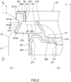
- Fig. 2 is a cross-sectional view of the sealing structure 1A.
- rolling elements 200 constituting the bearing are provided between an inner peripheral side member 3 to which the wheel is connected and an outer peripheral side member 2 provided on the outer side of the inner peripheral side member 3, and grease is enclosed to smooth the rotation of the rolling elements 200.
- the sealing structure 1A is provided in order to suppress leakage of the enclosed grease and entry of foreign matters into a space (sealing target space) in which the grease is enclosed.
- sealing structure 1E of the present embodiment similarly to the sealing structure 1A of the first embodiment, it is possible to improve the sealing performance while suppressing the complexity of a configuration.
- the present invention is not limited to the above-described embodiments, and includes other configurations and the like that can achieve the object of the present invention, and the following modifications and the like are also included in the present invention.
- the inner lip portions 512 and 513 extend toward the outer peripheral side as approaching the outer peripheral side member 2 in the axis x direction, but the inner lip portion may extend along the axis x direction or may extend toward the inner peripheral side as approaching the outer peripheral side member in the axis x direction.
- the inner lip portion can be pressed against a sliding contact target using the centrifugal force, and the sealing performance can be improved.
- the grease lip 412 and the side lip 413 as the outer lip portion are in direct sliding contact with the inner peripheral side member 3, but the outer lip may be configured to be in sliding contact with a target object (for example, a slinger) attached to the inner peripheral side member.
- a target object for example, a slinger
Landscapes
- Engineering & Computer Science (AREA)
- General Engineering & Computer Science (AREA)
- Mechanical Engineering (AREA)
- Sealing With Elastic Sealing Lips (AREA)
Abstract
A sealing structure capable of improving sealing performance while suppressing complication of a configuration is provided.
A sealing structure (1A) is a sealing structure for achieving sealing between an outer peripheral side member (2) and an inner peripheral side member (3) which are relatively rotatable and between which a rolling element is provided, the sealing structure including an outer seal member (4) that is attached to the outer peripheral side member (2) and has an outer lip portion (grease lip (412) and side lip (413)) that is in sliding contact with the inner peripheral side member (3) or a target object attached to the inner peripheral side member (3); and an inner seal member (5) that is attached to the inner peripheral side member (3), and has an inner lip portion (512) that is in sliding contact with the outer peripheral side member (2) or a target object attached to the outer peripheral side member (2). The grease lip (412) and the side lip (413) are provided closer to a sealing target space than the inner lip portion (512), and the inner seal member (5) is attached to a recess portion (321) formed in the inner peripheral side member (3).
Description
- The present invention relates to a sealing structure.
- In general, as a wheel bearing structure, a structure is known in which a rolling element is provided between an inner ring fixed to a hub wheel and an outer ring disposed on the outer side of the inner ring. In such a bearing structure, it has been proposed to provide a seal member for protection against muddy water (for example, refer to Patent Literature 1). In a wheel bearing device disclosed in Patent Literature 1, a metal ring is attached to a wheel mounting flange of an inner member, and a seal member is joined to the metal ring. The seal member attached to the metal ring is in sliding contact with an outer member on the outer side of a seal, which is mounted on the outer member and is in sliding contact with the metal ring, thereby protecting the seal from muddy water or the like.
- Patent Literature 1:
Japanese Patent Application Publication No. 2014-20413 - However, in the wheel bearing device disclosed in Patent Literature 1, the seal member is attached to an end portion of the metal ring, and the metal ring has to extend from a portion of the outer member serving as a sliding contact target of the seal to a portion where the sealing member is provided, which is likely to increase in size. On the other hand, in a configuration in which the seal is in direct sliding contact with the inner ring without providing the metal ring, it is difficult to provide the seal member, and it is difficult to improve sealing performance.
- The present invention has been made in view of the above-described problems, and an object thereof is to provide a sealing structure capable of improving sealing performance while suppressing complication of a configuration.
- In order to achieve the object, a sealing structure according to an aspect of the present invention is a sealing structure for achieving sealing between an outer peripheral side member and an inner peripheral side member which are relatively rotatable and between which a rolling element is provided, the sealing structure including an outer seal member that is attached to the outer peripheral side member and has an outer lip portion that is in sliding contact with the inner peripheral side member or a target object attached to the inner peripheral side member; and an inner seal member that is attached to the inner peripheral side member, and has an inner lip portion that is in sliding contact with the outer peripheral side member or a target object attached to the outer peripheral side member, in which the outer lip portion is provided closer to a sealing target space than the inner lip portion, and the inner seal member is attached to a recess portion formed in the inner peripheral side member.
- In the sealing structure according to an aspect of the present invention, the inner peripheral side member is rotatable about a predetermined axis, and the inner lip portion is inclined to extend toward an outer peripheral side as approaching the outer peripheral side member in an axis direction.
- In the sealing structure according to an aspect of the present invention, the inner lip portion is formed such that a base end portion is more easily deformed than a distal end portion.
- In the sealing structure according to an aspect of the present invention, the inner seal member includes an inner elastic body portion including the inner lip portion, and an inner reinforcement portion attached to the inner elastic body portion, the inner reinforcement portion covers the inner elastic body portion from at least an inner peripheral side, and the inner elastic body portion includes an outer peripheral surface portion in contact with an inner surface of the recess portion.
- In the sealing structure according to an aspect of the present invention, a slinger with which the inner lip portion is in sliding contact is attached to the outer peripheral side member.
- In the sealing structure according to an aspect of the present invention, the outer seal member includes an outer elastic body portion including the outer lip portion, and an outer reinforcement portion attached to the outer elastic body portion, and the slinger is integrally formed with the outer reinforcement portion.
- According to a sealing structure of the present invention, it is possible to improve sealing performance while suppressing complication of a configuration.
-
- [
Fig. 1 ] A cross-sectional view of a bearing structure provided with a sealing structure according to a first embodiment of the present invention. - [
Fig. 2 ] A cross-sectional view of the sealing structure according to the first embodiment of the present invention. - [
Fig. 3 ] A cross-sectional view of a sealing structure according to a second embodiment of the present invention. - [
Fig. 4 ] A cross-sectional view of a sealing structure according to a third embodiment of the present invention. - [
Fig. 5 ] A cross-sectional view of a sealing structure according to a fourth embodiment of the present invention. - [
Fig. 6 ] A cross-sectional view of a sealing structure according to a fifth embodiment of the present invention. - Hereinafter, embodiments of the present invention will be described with reference to the drawings. In second to fifth embodiments, members similar to those in a first embodiment are denoted by the same reference numerals, description thereof is omitted, and differences will be mainly described.
-
Fig. 1 is a cross-sectional view of abearing structure 100 provided with asealing structure 1A according to the first embodiment of the present invention, andFig. 2 is a cross-sectional view of thesealing structure 1A. In thebearing structure 100 provided with thesealing structure 1A,rolling elements 200 constituting the bearing are provided between an innerperipheral side member 3 to which the wheel is connected and an outerperipheral side member 2 provided on the outer side of the innerperipheral side member 3, and grease is enclosed to smooth the rotation of therolling elements 200. Although tworolling elements 200 are provided in the illustrated example, the number ofrolling elements 200 is not particularly limited. Thesealing structure 1A is provided in order to suppress leakage of the enclosed grease and entry of foreign matters into a space (sealing target space) in which the grease is enclosed. - The
sealing structure 1A according to the first embodiment of the present invention is a sealing structure for achieving sealing between the outerperipheral side member 2 and the innerperipheral side member 3 which are relatively rotatable and between which therolling element 200 is provided, thesealing structure 1A including anouter seal member 4 that is attached to the outerperipheral side member 2 and has an outer lip portion (agrease lip 412 and a side lip 413) that is in sliding contact with the innerperipheral side member 3 or a target object attached to the innerperipheral side member 3; and aninner seal member 5 that is attached to the innerperipheral side member 3, and has aninner lip portion 512 that is in sliding contact with the outerperipheral side member 2 or a target object attached to the outerperipheral side member 2. Thegrease lip 412 and theside lip 413 are provided closer to a sealing target space than theinner lip portion 512, and theinner seal member 5 is attached to arecess portion 321 formed in the innerperipheral side member 3. - Hereinafter, for convenience of description, an arrow a (refer to
Fig. 2 ) direction in an axis x direction of thesealing structure 1A is defined as one side, and an arrow b (refer toFig. 2 ) direction in the axis x direction is defined as the other side. In addition, in a direction perpendicular to the axis x (hereinafter, also referred to as a "radial direction"), a direction away from the axis x (an arrow c direction inFig. 2 ) is defined as an outer peripheral side, and a direction approaching the axis x (an arrow d direction inFig. 2 ) is defined as an inner peripheral side. In the following description, when describing positional relationships and directions of each member, positional relationships and directions in the drawings are merely indicated, and positional relationships and directions when each member is assembled in an actual vehicle or the like are not indicated. - The outer
peripheral side member 2 is a so-called outer ring, and is provided so as not to be rotatable with respect to a vehicle or the like. The outerperipheral side member 2 has atubular portion 21 having a cylindrical shape extending along the axis x direction, in a portion where theouter seal member 4 is provided. Thetubular portion 21 is open to the one side in the axis x direction. - The inner
peripheral side member 3 is a so-called inner ring provided to be rotatable with respect to the outerperipheral side member 2, and includes awheel mounting flange 30 to which a wheel is connected. The innerperipheral side member 3 may be divided into a plurality of portions, and the portion illustrated inFig. 2 may not be directly connected to the wheel. That is, the innerperipheral side member 3 may be any component that is rotated together with the wheel. The innerperipheral side member 3 includes acolumnar portion 31 having a columnar shape which extends along the axis x direction and is disposed on the inner peripheral side of thetubular portion 21, and aflange portion 32 that is continuous with an end portion of thecolumnar portion 31 on the one side in the axis x direction and extends toward the outer peripheral side. Therecess portion 321 is formed on asurface 322 of theflange portion 32, which faces the other side in the axis x direction. In addition, a portion of theflange portion 32 where therecess portion 321 is formed extends along a surface orthogonal to the axis x direction, and is particularly a portion on the outer peripheral side of such a plane. In addition, a position where therecess portion 321 is formed is a position facing anend face 212 of the outerperipheral side member 2 in the axis x direction. - An inner
peripheral surface 211 of thetubular portion 21 and an outerperipheral surface 311 of thecolumnar portion 31 are disposed with a gap therebetween, and in this gap, rolling elements are provided and grease is enclosed. That is, a space between the innerperipheral surface 211 and the outerperipheral surface 311 is a sealing target space. In addition, a direction from the other side to the one side in the axis x direction is a direction from the sealing target space side to the atmosphere side, and a direction from the inner peripheral side to the outer peripheral side is a direction from the sealing target space side to the atmosphere side. - The
outer seal member 4 includes an outerelastic body portion 41, and anouter reinforcement portion 42 attached to the outerelastic body portion 41, and is attached to the innerperipheral surface 211 of thetubular portion 21. The elastic body of the outerelastic body portion 41 is, for example, a rubber material such as fluororubber, acrylic rubber, nitrile rubber, or hydrogenated nitrile rubber. Theouter reinforcement portion 42 is made of metal, for example, and is manufactured by press working or forging, and the outerelastic body portion 41 is molded through cross-linking (vulcanization) molding using a molding die. The outerelastic body portion 41 is formed integrally with theouter reinforcement portion 42. - The outer
elastic body portion 41 includes anannular portion 411 formed in an annular shape around the axis x, and thegrease lip 412 and theside lip 413 as the outer lip portion protruding from an inner peripheral side end portion of theannular portion 411. An end edge of theannular portion 411 on the outer peripheral side is in contact with the innerperipheral surface 211 of thetubular portion 21, so that the sealing performance between thetubular portion 21 and theouter reinforcement portion 42 is secured. - The
grease lip 412 protrudes toward the inner peripheral side, is inclined toward the other side in the axis x direction as thegrease lip 412 goes toward the inner peripheral side, and is in sliding contact with the outerperipheral surface 311 of thecolumnar portion 31. Theside lip 413 protrudes toward the one side in the axis x direction, is inclined toward the outer peripheral side as theside lip 413 goes toward the one side in the axis x direction, and is in sliding contact with thesurface 322 of theflange portion 32 facing the other side in the axis x direction. Theside lip 413 is provided closer to the atmosphere side than thegrease lip 412, and suppresses the entry of foreign matters such as muddy water into a portion between thegrease lip 412 and thecolumnar portion 31. In addition, in the present embodiment, oneside lip 413 is provided. - The
outer reinforcement portion 42 integrally includes atubular portion 421 having a cylindrical shape extending along the axis x direction, and anannular portion 422 that is continuous with an end portion of thetubular portion 421 on the one side in the axis x direction and extends toward the inner peripheral side. The outerelastic body portion 41 is provided to cover a surface of theannular portion 422 on one side in the axis x direction. - The
inner seal member 5 includes an innerelastic body portion 51, and aninner reinforcement portion 52 attached to the innerelastic body portion 51, and is attached to therecess portion 321 of the innerperipheral side member 3. A method of attaching theinner seal member 5 to therecess portion 321 is not particularly limited, and theinner seal member 5 may be attached by, for example, metal fitting. The elastic body of the innerelastic body portion 51 is, for example, a rubber material such as fluororubber, acrylic rubber, nitrile rubber, or hydrogenated nitrile rubber. Theinner reinforcement portion 52 is made of metal, for example, and is manufactured by press working or forging, and the innerelastic body portion 51 is molded through cross-linking (vulcanization) molding using a molding die. The innerelastic body portion 51 is formed integrally with theinner reinforcement portion 52. - The inner
elastic body portion 51 includes anattachment portion 511 disposed in therecess portion 321, and theinner lip portion 512 protruding from theattachment portion 511 toward the other side in the axis x direction. In theattachment portion 511 having a substantially rectangular cross section, an outerperipheral surface portion 511A is exposed without being covered with theinner reinforcement portion 52, and the outerperipheral surface portion 511A is in contact with the inner peripheral surface of therecess portion 321. In addition, the outerperipheral surface portion 511A is inclined toward the outer peripheral side as the outerperipheral surface portion 511A goes toward the other side in the axis x direction (such that the dimension in the radial direction is decreased as the outer peripheral surface portion goes toward the bottom portion of the recess portion 321), and has aprotrusion portion 511B at the end portion on the other side in the axis x direction. - The
inner lip portion 512 is inclined toward the outer peripheral side as theinner lip portion 512 goes toward the other side in the axis x direction (that is, as theinner lip portion 512 goes toward the outer peripheral side member 2), and abase end portion 512B is formed thinner (the dimension in the radial direction is smaller) than adistal end portion 512A. That is, thedistal end portion 512A is heavier and has higher rigidity than thebase end portion 512B, and thebase end portion 512B is more easily deformed than thedistal end portion 512A. - The
distal end portion 512A is in sliding contact with theend face 212 of thetubular portion 21 on one side in the axis x direction, so that theinner lip portion 512 is in linear contact with the outerperipheral side member 2. In addition, theend face 212 has a planar shape along a plane orthogonal to the axis x direction, and theinner lip portion 512 is in sliding contact with such a planar portion. - The
grease lip 412 and theside lip 413 as the outer lip portion are provided on the sealing target space side with respect to theinner lip portion 512. That is, theinner lip portion 512 suppresses the entry of foreign matters such as muddy water into a portion between thegrease lip 412 and theside lip 413 and the innerperipheral side member 3. In addition, theinner lip portion 512 is provided on the outer peripheral side with respect to thegrease lip 412 and theside lip 413. - The
inner reinforcement portion 52 integrally includes atubular portion 521 having a cylindrical shape extending along the axis x direction, and anannular portion 522 that is continuous with an end portion of thetubular portion 521 on the one side in the axis x direction and extends toward the outer peripheral side, and is formed to have an L-shaped cross section. Theinner reinforcement portion 52 covers the inner peripheral surface of theattachment portion 511 having a substantially rectangular cross section and a part of a surface on one side in the axis x direction. At least on the other side in the axis x direction, the total dimension of theattachment portion 511 and theinner reinforcement portion 52 in the radial direction is equal to or slightly larger than the dimension of therecess portion 321 in the radial direction, theattachment portion 511 is in close contact with the inner surface of therecess portion 321, and the sealing performance is secured. - In the sealing
structure 1A as described above, when foreign matters such as muddy water try to enter from the atmosphere side toward the sealing target space side, the entry is first suppressed by theinner lip portion 512. When foreign matters pass through theinner lip portion 512, next, the entry is suppressed by theside lip 413. At this time, since theinner lip portion 512 and theside lip 413 are alternately provided (extend from the innerperipheral side member 3 and the outerperipheral side member 2, respectively), the foreign matters passing through theinner lip portion 512 pass through the vicinity of the distal end of theinner lip portion 512, and easily reach the vicinity of the base end of theside lip 413. That is, the foreign matters having passed through theinner lip portion 512 hardly pass through theside lip 413. - As described above, the entry of foreign matters to the
grease lip 412 is suppressed, and generation of rust due to the foreign matters and wear of each lip due to the rust are suppressed. In addition, it is possible to suppress a decrease in sealing performance due to the rust or wear, and an increase in torque for rotating the wheel (hereinafter, simply referred to as "torque" in some cases) due to an increase in frictional force. - In addition, when the inner
peripheral side member 3 is rotated, theinner lip portion 512 inclined toward the outer peripheral side tends to further move toward the outer peripheral side by the centrifugal force generated by the rotation. As a result, the force with which theinner lip portion 512 presses the outerperipheral side member 2 is reduced, and the torque for rotating the wheel is reduced. - As described above, with the sealing
structure 1A according to the first embodiment of the present invention, since theinner seal member 5 is attached to therecess portion 321 of the innerperipheral side member 3, it is not necessary to provide a slinger for the attachment of theinner seal member 5 or extend the slinger, and it is possible to suppress complication of a configuration. In this way, theinner seal member 5 can be easily provided, and the sealing performance can be improved as compared with a configuration in which sealing is achieved only by the seal provided on the outerperipheral side member 2. - In addition, by providing the
inner seal member 5, the number of seals in theouter seal member 4 can be reduced, and the torque can be easily reduced using the centrifugal force in the rotatinginner seal member 5. Therefore, as compared with the configuration in which seals are provided only on the outerperipheral side member 2, the total torque can be reduced even when the total number of seals is the same. - In addition, since the
inner lip portion 512 extends toward the outer peripheral side as approaching the outerperipheral side member 2 in the axis x direction, theinner lip portion 512 can be deformed by the centrifugal force to reduce torque. - Furthermore, since the
base end portion 512B is more easily deformed than thedistal end portion 512A in theinner lip portion 512, deformation using the centrifugal force is likely to occur as described above, and torque can be more easily reduced. - In addition, since the
inner seal member 5 has theinner reinforcement portion 52, deformation of the innerelastic body portion 51 can be suppressed. At this time, the outerperipheral surface portion 511A of the innerelastic body portion 51 is in contact with the inner surface of therecess portion 321, so that the sealing performance therebetween can be improved. In particular, since theprotrusion portion 511B is formed on the outerperipheral surface portion 511A, theprotrusion portion 511B is easily pressed against therecess portion 321. - As illustrated in
Fig. 3 , in a sealingstructure 1B of the present embodiment, aninner seal member 5B and an outerelastic body portion 41B of theouter seal member 4 are different from the sealingstructure 1A of the first embodiment, and other structures are similar. - The
inner seal member 5B does not have an inner reinforcement portion, and the inner peripheral surface, the outer peripheral surface, and the surface on one side in the axis x direction of theattachment portion 511 are in contact with the inner surface of therecess portion 321. In addition, aninner lip portion 513 of theinner seal member 5B has a substantially constant thickness, and the ease of deformation from the base end portion to the distal end portion is substantially the same. - The outer
elastic body portion 41B has, in addition to thegrease lip 412 and theside lip 413, anintermediate lip 414 disposed between thegrease lip 412 and theside lip 413. Theintermediate lip 414 is in sliding contact with a transition region between thecolumnar portion 31 and theflange portion 32. - With the sealing
structure 1B of the present embodiment, similarly to the sealingstructure 1A of the first embodiment, it is possible to improve the sealing performance while suppressing the complexity of a configuration. - As illustrated in
Fig. 4 , in a sealingstructure 1C of the present embodiment, aninner seal member 5C is different from the sealingstructure 1A of the first embodiment, and other structures are similar. - Similarly to the
inner seal member 5B in the second embodiment, theinner seal member 5C does not have an inner reinforcement portion but has theattachment portion 511 having the same form. In addition, theinner seal member 5C has theinner lip portion 512 similar to that of the first embodiment. - With the sealing
structure 1C of the present embodiment, similarly to the sealingstructure 1A of the first embodiment, it is possible to improve the sealing performance while suppressing the complexity of a configuration. - As illustrated in
Fig. 5 , a sealingstructure 1D of the present embodiment is different from the sealingstructure 1A of the first embodiment in that aslinger 6 is provided, and other structures are similar. - The
slinger 6 integrally includes atubular portion 61 having a cylindrical shape extending along the axis x direction, and anannular portion 62 that is continuous with an end portion of thetubular portion 61 on the one side in the axis x direction and extends toward the inner peripheral side, and is formed to have an L-shaped cross section. Theslinger 6 is attached to the outerperipheral side member 2 such that thetubular portion 61 covers an outerperipheral surface 213 of thetubular portion 21 and theannular portion 62 covers theend face 212 of thetubular portion 21 on one side in the axis x direction. Theinner lip portion 512 is not in direct sliding contact with the outerperipheral side member 2 but is in sliding contact with theslinger 6 as a target object attached to the outerperipheral side member 2. Note that an elastic member for sealing is preferably provided between theslinger 6 and thetubular portion 21. - With the sealing
structure 1D of the present embodiment, similarly to the sealingstructure 1A of the first embodiment, it is possible to improve the sealing performance while suppressing the complexity of a configuration. - Furthermore, since the
slinger 6 is provided, the surface state (smoothness, surface roughness, and the like) of the sliding contact surface can be easily managed as compared with the configuration in which theinner lip portion 512 is in direct sliding contact with the outerperipheral side member 2. - As illustrated in
Fig. 6 , in a sealingstructure 1E of the present embodiment, anouter reinforcement portion 42E of theouter seal member 4 is different from the sealingstructure 1A of the first embodiment, and other structures are similar. - The
outer reinforcement portion 42E integrally includes adouble tubular portion 421E extending along the axis x direction, anannular portion 422E that is continuous with the end portion of thedouble tubular portion 421E on the one side in the axis x direction and extends toward the inner peripheral side, and aslinger 423 that is continuous with the end portion of thedouble tubular portion 421E on the one side in the axis x direction and extends toward the outer peripheral side. Thedouble tubular portion 421E extends in a cylindrical shape from one side toward the other side in the axis x direction along the innerperipheral surface 211 of thetubular portion 21, and then is folded back toward the inner peripheral side to extend in a cylindrical shape toward the other side. - The
slinger 423 covers theend face 212 of thetubular portion 21 on one side in the axis x direction. Theinner lip portion 512 is not in direct sliding contact with the outerperipheral side member 2 but is in sliding contact with theslinger 423 as a target object attached to the outerperipheral side member 2. Note that an elastic member that seals a portion between theouter reinforcement portion 42E and thetubular portion 21 is preferably provided, for example, between theslinger 423 and thetubular portion 21. - With the sealing
structure 1E of the present embodiment, similarly to the sealingstructure 1A of the first embodiment, it is possible to improve the sealing performance while suppressing the complexity of a configuration. - Furthermore, since the
slinger 423 is provided, similarly to the fourth embodiment, it is possible to easily manage the surface state such as the smoothness and the surface roughness of the sliding contact surface. In addition, since theslinger 423 is integrally formed with theouter reinforcement portion 42E, an increase in the number of components can be suppressed. - Note that the present invention is not limited to the above-described embodiments, and includes other configurations and the like that can achieve the object of the present invention, and the following modifications and the like are also included in the present invention. For example, in the above-described embodiments, the
inner lip portions peripheral side member 2 in the axis x direction, but the inner lip portion may extend along the axis x direction or may extend toward the inner peripheral side as approaching the outer peripheral side member in the axis x direction. In a case where the inner lip portion extends toward the inner peripheral side, the inner lip portion can be pressed against a sliding contact target using the centrifugal force, and the sealing performance can be improved. - In addition, in the above-described embodiments, the
grease lip 412 and theside lip 413 as the outer lip portion are in direct sliding contact with the innerperipheral side member 3, but the outer lip may be configured to be in sliding contact with a target object (for example, a slinger) attached to the inner peripheral side member. - In addition, the configurations described in the first to fifth embodiments can be combined with each other. For example, the configuration in which the inner reinforcement portion is not provided as in the second and third embodiments and the configuration in which the slinger is provided as in the fourth and fifth embodiments may be combined.
- The embodiments of the present invention have been described above, but the present invention is not limited to the sealing structures according to the embodiments of the present invention, and includes all aspects included in the concept and claims of the present invention. In addition, each configuration may be appropriately and selectively combined to achieve at least a part of the above-described problems and effects. For example, the shape, material, arrangement, size, and the like of each constituent element in the embodiments described above can be appropriately changed according to a specific usage aspect of the present invention.
-
- 1A to 1E sealing structure
- 2 outer peripheral side member
- 21 tubular portion
- 211 inner peripheral surface
- 212 end face
- 213 outer peripheral surface
- 3 inner peripheral side member
- 31 columnar portion
- 311 outer peripheral surface
- 32 flange portion
- 321 recess portion
- 4 outer seal member
- 41 outer elastic body portion
- 411 annular portion
- 412 grease lip
- 413 side lip
- 414 intermediate lip
- 42, 42E outer reinforcement portion
- 421 tubular portion
- 421E double tubular portion
- 422, 422E annular portion
- 5, 5B, 5C inner seal member
- 51 inner elastic body portion
- 511 attachment portion
- 511A outer peripheral surface portion
- 511B protrusion portion
- 512, 513 inner lip portion
- 512A distal end portion
- 512B base end portion
- 52 inner reinforcement portion
- 521 tubular portion
- 522 annular portion
- 6, 423 slinger
- 61 tubular portion
- 62 annular portion
Claims (6)
- A sealing structure for achieving sealing between an outer peripheral side member and an inner peripheral side member which are relatively rotatable and between which a rolling element is provided, the sealing structure comprising:an outer seal member that is attached to the outer peripheral side member and has an outer lip portion that is in sliding contact with the inner peripheral side member or a target object attached to the inner peripheral side member; andan inner seal member that is attached to the inner peripheral side member, and has an inner lip portion that is in sliding contact with the outer peripheral side member or a target object attached to the outer peripheral side member, whereinthe outer lip portion is provided closer to a sealing target space than the inner lip portion, andthe inner seal member is attached to a recess portion formed in the inner peripheral side member.
- The sealing structure according to claim 1, whereinthe inner peripheral side member is rotatable about a predetermined axis, andthe inner lip portion is inclined to extend toward an outer peripheral side as approaching the outer peripheral side member in an axis direction.
- The sealing structure according to claim 2, wherein the inner lip portion is formed such that a base end portion is more easily deformed than a distal end portion.
- The sealing structure according to any one of claims 1 to 3, whereinthe inner seal member includes an inner elastic body portion including the inner lip portion, and an inner reinforcement portion attached to the inner elastic body portion,the inner reinforcement portion covers the inner elastic body portion from at least an inner peripheral side, andthe inner elastic body portion includes an outer peripheral surface portion in contact with an inner surface of the recess portion.
- The sealing structure according to any one of claims 1 to 3, wherein a slinger with which the inner lip portion is in sliding contact is attached to the outer peripheral side member.
- The sealing structure according to claim 5, whereinthe outer seal member includes an outer elastic body portion including the outer lip portion, and an outer reinforcement portion attached to the outer elastic body portion, andthe slinger is integrally formed with the outer reinforcement portion.
Applications Claiming Priority (2)
| Application Number | Priority Date | Filing Date | Title |
|---|---|---|---|
| JP2022138233 | 2022-08-31 | ||
| PCT/JP2023/031110 WO2024048552A1 (en) | 2022-08-31 | 2023-08-29 | Sealing structure |
Publications (1)
| Publication Number | Publication Date |
|---|---|
| EP4582714A1 true EP4582714A1 (en) | 2025-07-09 |
Family
ID=90099534
Family Applications (1)
| Application Number | Title | Priority Date | Filing Date |
|---|---|---|---|
| EP23860314.6A Pending EP4582714A1 (en) | 2022-08-31 | 2023-08-29 | Sealing structure |
Country Status (4)
| Country | Link |
|---|---|
| EP (1) | EP4582714A1 (en) |
| JP (1) | JPWO2024048552A1 (en) |
| CN (1) | CN119790243A (en) |
| WO (1) | WO2024048552A1 (en) |
Family Cites Families (9)
| Publication number | Priority date | Publication date | Assignee | Title |
|---|---|---|---|---|
| JPS62181720U (en) * | 1986-05-12 | 1987-11-18 | ||
| JPH02138279U (en) * | 1989-04-24 | 1990-11-19 | ||
| JPH0741973Y2 (en) * | 1990-04-27 | 1995-09-27 | 内山工業株式会社 | Sealing device |
| JPH0728227U (en) * | 1993-10-29 | 1995-05-23 | エヌティエヌ株式会社 | Bearing sealing device |
| JP2004183686A (en) * | 2002-11-29 | 2004-07-02 | Nsk Ltd | Rolling bearing and sealing device |
| JP2005016603A (en) * | 2003-06-25 | 2005-01-20 | Nsk Ltd | Sealing device and rolling bearing unit with sealing device |
| JP5158389B2 (en) * | 2008-11-28 | 2013-03-06 | Nok株式会社 | Sealing device |
| JP2012172725A (en) * | 2011-02-18 | 2012-09-10 | Nsk Ltd | Outer ring rotation-type rolling bearing, and rolling mill |
| JP5988738B2 (en) | 2012-07-13 | 2016-09-07 | Ntn株式会社 | Wheel bearing device |
-
2023
- 2023-08-29 EP EP23860314.6A patent/EP4582714A1/en active Pending
- 2023-08-29 CN CN202380062758.5A patent/CN119790243A/en active Pending
- 2023-08-29 WO PCT/JP2023/031110 patent/WO2024048552A1/en not_active Ceased
- 2023-08-29 JP JP2024544266A patent/JPWO2024048552A1/ja active Pending
Also Published As
| Publication number | Publication date |
|---|---|
| JPWO2024048552A1 (en) | 2024-03-07 |
| CN119790243A (en) | 2025-04-08 |
| WO2024048552A1 (en) | 2024-03-07 |
Similar Documents
| Publication | Publication Date | Title |
|---|---|---|
| CN112901663B (en) | Sealing device | |
| US20100066030A1 (en) | Hermetic sealing device | |
| EP2857703B1 (en) | Outer ring rotation bearing | |
| US20200124178A1 (en) | Sealing apparatus | |
| CN114635915A (en) | Sealing device | |
| JP7311614B2 (en) | sealing device | |
| EP3604868A1 (en) | Sealing device | |
| EP3822503A1 (en) | Sealing device | |
| EP3779246B1 (en) | Seal device | |
| JP2016080020A (en) | Sealing device | |
| US6953193B2 (en) | Sealing apparatus | |
| US12529397B2 (en) | Sealing device for hub bearing | |
| EP3971452A1 (en) | Sealing device | |
| US11692591B2 (en) | Sealing device for a bearing unit | |
| JP6872430B2 (en) | Sealing device | |
| WO2024048552A1 (en) | Sealing structure | |
| JP7527930B2 (en) | Sealing device | |
| JP6817698B2 (en) | Rolling bearings with sealing flanges | |
| JP7575152B1 (en) | Oil seal | |
| US12442411B2 (en) | Sealing device | |
| JP7523787B2 (en) | Sealing device | |
| JP2024056552A (en) | Sealing structure | |
| JP2026081693A (en) | sealing device | |
| EP4224028A1 (en) | Sealing device | |
| JP2026028513A (en) | sealing device |
Legal Events
| Date | Code | Title | Description |
|---|---|---|---|
| STAA | Information on the status of an ep patent application or granted ep patent |
Free format text: STATUS: THE INTERNATIONAL PUBLICATION HAS BEEN MADE |
|
| PUAI | Public reference made under article 153(3) epc to a published international application that has entered the european phase |
Free format text: ORIGINAL CODE: 0009012 |
|
| STAA | Information on the status of an ep patent application or granted ep patent |
Free format text: STATUS: REQUEST FOR EXAMINATION WAS MADE |
|
| 17P | Request for examination filed |
Effective date: 20250328 |
|
| AK | Designated contracting states |
Kind code of ref document: A1 Designated state(s): AL AT BE BG CH CY CZ DE DK EE ES FI FR GB GR HR HU IE IS IT LI LT LU LV MC ME MK MT NL NO PL PT RO RS SE SI SK SM TR |
|
| DAV | Request for validation of the european patent (deleted) | ||
| DAX | Request for extension of the european patent (deleted) |