EP4582682A1 - Hybrid electric gas turbine engine two speed transmission for low spool drive power injection and power extraction - Google Patents
Hybrid electric gas turbine engine two speed transmission for low spool drive power injection and power extraction Download PDFInfo
- Publication number
- EP4582682A1 EP4582682A1 EP24221300.7A EP24221300A EP4582682A1 EP 4582682 A1 EP4582682 A1 EP 4582682A1 EP 24221300 A EP24221300 A EP 24221300A EP 4582682 A1 EP4582682 A1 EP 4582682A1
- Authority
- EP
- European Patent Office
- Prior art keywords
- transmission
- spool
- low
- speed
- operative communication
- Prior art date
- Legal status (The legal status is an assumption and is not a legal conclusion. Google has not performed a legal analysis and makes no representation as to the accuracy of the status listed.)
- Pending
Links
Images



Classifications
-
- F—MECHANICAL ENGINEERING; LIGHTING; HEATING; WEAPONS; BLASTING
- F02—COMBUSTION ENGINES; HOT-GAS OR COMBUSTION-PRODUCT ENGINE PLANTS
- F02C—GAS-TURBINE PLANTS; AIR INTAKES FOR JET-PROPULSION PLANTS; CONTROLLING FUEL SUPPLY IN AIR-BREATHING JET-PROPULSION PLANTS
- F02C7/00—Features, components parts, details or accessories, not provided for in, or of interest apart form groups F02C1/00 - F02C6/00; Air intakes for jet-propulsion plants
- F02C7/32—Arrangement, mounting, or driving, of auxiliaries
-
- F—MECHANICAL ENGINEERING; LIGHTING; HEATING; WEAPONS; BLASTING
- F01—MACHINES OR ENGINES IN GENERAL; ENGINE PLANTS IN GENERAL; STEAM ENGINES
- F01D—NON-POSITIVE DISPLACEMENT MACHINES OR ENGINES, e.g. STEAM TURBINES
- F01D15/00—Adaptations of machines or engines for special use; Combinations of engines with devices driven thereby
- F01D15/10—Adaptations for driving, or combinations with, electric generators
-
- F—MECHANICAL ENGINEERING; LIGHTING; HEATING; WEAPONS; BLASTING
- F02—COMBUSTION ENGINES; HOT-GAS OR COMBUSTION-PRODUCT ENGINE PLANTS
- F02C—GAS-TURBINE PLANTS; AIR INTAKES FOR JET-PROPULSION PLANTS; CONTROLLING FUEL SUPPLY IN AIR-BREATHING JET-PROPULSION PLANTS
- F02C7/00—Features, components parts, details or accessories, not provided for in, or of interest apart form groups F02C1/00 - F02C6/00; Air intakes for jet-propulsion plants
- F02C7/36—Power transmission arrangements between the different shafts of the gas turbine plant, or between the gas-turbine plant and the power user
-
- F—MECHANICAL ENGINEERING; LIGHTING; HEATING; WEAPONS; BLASTING
- F16—ENGINEERING ELEMENTS AND UNITS; GENERAL MEASURES FOR PRODUCING AND MAINTAINING EFFECTIVE FUNCTIONING OF MACHINES OR INSTALLATIONS; THERMAL INSULATION IN GENERAL
- F16H—GEARING
- F16H37/00—Combinations of mechanical gearings, not provided for in groups F16H1/00 - F16H35/00
- F16H37/02—Combinations of mechanical gearings, not provided for in groups F16H1/00 - F16H35/00 comprising essentially only toothed or friction gearings
- F16H37/06—Combinations of mechanical gearings, not provided for in groups F16H1/00 - F16H35/00 comprising essentially only toothed or friction gearings with a plurality of driving or driven shafts; with arrangements for dividing torque between two or more intermediate shafts
- F16H37/065—Combinations of mechanical gearings, not provided for in groups F16H1/00 - F16H35/00 comprising essentially only toothed or friction gearings with a plurality of driving or driven shafts; with arrangements for dividing torque between two or more intermediate shafts with a plurality of driving or driven shafts
-
- F—MECHANICAL ENGINEERING; LIGHTING; HEATING; WEAPONS; BLASTING
- F16—ENGINEERING ELEMENTS AND UNITS; GENERAL MEASURES FOR PRODUCING AND MAINTAINING EFFECTIVE FUNCTIONING OF MACHINES OR INSTALLATIONS; THERMAL INSULATION IN GENERAL
- F16H—GEARING
- F16H57/00—General details of gearing
- F16H57/02—Gearboxes; Mounting gearing therein
- F16H57/038—Gearboxes for accommodating bevel gears
-
- F—MECHANICAL ENGINEERING; LIGHTING; HEATING; WEAPONS; BLASTING
- F05—INDEXING SCHEMES RELATING TO ENGINES OR PUMPS IN VARIOUS SUBCLASSES OF CLASSES F01-F04
- F05D—INDEXING SCHEME FOR ASPECTS RELATING TO NON-POSITIVE-DISPLACEMENT MACHINES OR ENGINES, GAS-TURBINES OR JET-PROPULSION PLANTS
- F05D2220/00—Application
- F05D2220/70—Application in combination with
- F05D2220/76—Application in combination with an electrical generator
-
- F—MECHANICAL ENGINEERING; LIGHTING; HEATING; WEAPONS; BLASTING
- F05—INDEXING SCHEMES RELATING TO ENGINES OR PUMPS IN VARIOUS SUBCLASSES OF CLASSES F01-F04
- F05D—INDEXING SCHEME FOR ASPECTS RELATING TO NON-POSITIVE-DISPLACEMENT MACHINES OR ENGINES, GAS-TURBINES OR JET-PROPULSION PLANTS
- F05D2260/00—Function
- F05D2260/40—Transmission of power
- F05D2260/403—Transmission of power through the shape of the drive components
- F05D2260/4031—Transmission of power through the shape of the drive components as in toothed gearing
-
- F—MECHANICAL ENGINEERING; LIGHTING; HEATING; WEAPONS; BLASTING
- F16—ENGINEERING ELEMENTS AND UNITS; GENERAL MEASURES FOR PRODUCING AND MAINTAINING EFFECTIVE FUNCTIONING OF MACHINES OR INSTALLATIONS; THERMAL INSULATION IN GENERAL
- F16H—GEARING
- F16H57/00—General details of gearing
- F16H57/02—Gearboxes; Mounting gearing therein
- F16H2057/02013—Extension units for gearboxes, e.g. additional units attached to a main gear
-
- F—MECHANICAL ENGINEERING; LIGHTING; HEATING; WEAPONS; BLASTING
- F16—ENGINEERING ELEMENTS AND UNITS; GENERAL MEASURES FOR PRODUCING AND MAINTAINING EFFECTIVE FUNCTIONING OF MACHINES OR INSTALLATIONS; THERMAL INSULATION IN GENERAL
- F16H—GEARING
- F16H57/00—General details of gearing
- F16H57/02—Gearboxes; Mounting gearing therein
- F16H2057/02034—Gearboxes combined or connected with electric machines
-
- F—MECHANICAL ENGINEERING; LIGHTING; HEATING; WEAPONS; BLASTING
- F16—ENGINEERING ELEMENTS AND UNITS; GENERAL MEASURES FOR PRODUCING AND MAINTAINING EFFECTIVE FUNCTIONING OF MACHINES OR INSTALLATIONS; THERMAL INSULATION IN GENERAL
- F16H—GEARING
- F16H57/00—General details of gearing
- F16H57/02—Gearboxes; Mounting gearing therein
- F16H2057/02039—Gearboxes for particular applications
- F16H2057/02082—Gearboxes for particular applications for application in vehicles other than propelling, e.g. adjustment of parts
-
- F—MECHANICAL ENGINEERING; LIGHTING; HEATING; WEAPONS; BLASTING
- F16—ENGINEERING ELEMENTS AND UNITS; GENERAL MEASURES FOR PRODUCING AND MAINTAINING EFFECTIVE FUNCTIONING OF MACHINES OR INSTALLATIONS; THERMAL INSULATION IN GENERAL
- F16H—GEARING
- F16H2200/00—Transmissions for multiple ratios
- F16H2200/003—Transmissions for multiple ratios characterised by the number of forward speeds
- F16H2200/0034—Transmissions for multiple ratios characterised by the number of forward speeds the gear ratios comprising two forward speeds
Definitions
- the present disclosure is directed to the improved hybrid electric gas turbine engine two speed transmission for low spool drive.
- Hybrid electric gas turbine engines in a parallel-hybrid arrangement, require coupling of electric machines referred to as motor-generators MG, to the main shafts of the engine to provide power extraction and power injection, see Fig. 1 .
- motor-generators MG electric machines referred to as motor-generators MG
- this is done by mounting the motor-generators MG to an accessory gearbox AG.
- gearbox mounted arrangements a high spool HS towershaft and low spool LS towershaft are provided to mechanically link the motor-generators MG to the main shafts of the engine.
- the machines are directly driven with a fixed gear ratio off the accessory gearbox AG, without a transmission.
- the motor-generators MG are then optimized to the speed ranges of the N1 and N2 spools across idle to redline mechanical shaft speeds.
- Low spool speed ranges are large, and as a result impose significant design challenges on motor-generator design, and thermal management.
- a hybrid electric gas turbine engine two speed transmission for a low spool drive comprising an accessory gearbox in operative communication with a low speed spool motor-generator; a transmission in operative communication with the accessory gearbox and the low speed spool motor-generator; a low speed spool angled gearbox in operative communication with the transmission; and a low speed spool in operative communication with the low speed spool angled gearbox.
- Particular embodiments further may include at least one, or a plurality of, the following optional features, alone or in combination with each other:
- a further embodiment of any of the foregoing embodiments may additionally and/or alternatively include the accessory gearbox is in operative communication with an oil pump and a fuel pump.
- a further embodiment of any of the foregoing embodiments may additionally and/or alternatively include the accessory gearbox is in operative communication with a first high speed spool motor-generator and a second high speed spool motor-generator.
- a further embodiment of any of the foregoing embodiments may additionally and/or alternatively include the transmission comprises a two speed transmission configured for hybrid electric low spool drive applications.
- An N1 low speed spool motor-generator 86 is in operative communication with the accessory gearbox 72.
- a transmission 88 is in operative communication with the accessory gearbox 72 and driven by the N1 motor-generator 86.
- the final gear ratio of the N1 motor-generator 86 can be provided within the accessory gearbox 72.
- the transmission 88 is also in operative communication with an N1 low speed spool angled gearbox 90.
- the N1 angled gearbox 90 is in operative communication with the low speed spool 30 (N1) via towershaft 60.
- the transmission 88 can be a two-speed transmission.
- the transmission 88 can be a line removeable unit that is bolted to the accessory gearbox 72.
- the transmission 88 can be bolted to the N1 angled gear box 90, with each being separate units as shown in Fig. 5 .
- the transmission 88 and N1 angled gearbox 90 are integrally formed sharing a common housing 92.
- the housing 92 can be a line removable unit that is bolted to the accessory gearbox 72.
- the transmission 88 comprises a two speed transmission for hybrid electric low spool drive applications.
- the transmission 88 comprises clutch packs and an epicyclic geartrain configured to reduce the speed range at the low speed spool N1 motor-generator 86.
- the transmission 88 is attached to the core-mounted accessory gearbox 72 and utilizes a low speed spool towershaft 94 as an input coupling.
- the transmission 88 is integrally housed with the N1 angled gearbox 90.
- N1 angled gearbox 90 includes bevel gears 64 at the input, and an N2 coupling shaft 96 at the output for the accessory gearbox 72.
- the hybrid electric gas turbine engine two speed transmission for low spool drive 70 is a core mounted scheme with a towershaft 60 in operative communication with the compressor section 24.
- the N1 angled gearbox 90 is shown coupled to the towershaft 60.
- the transmission 88 is coupled to the N1 angled gearbox 90.
- the transmission 88 is coupled to the accessory gearbox 72.
- the accessory gearbox 72 is coupled to the motor-generator 86.
- Fig. 8 and Fig. 9 process maps are shown. Though illustrated as distinct steps, two or more of the steps 100-108 and 112-122 of Fig. 8 and Fig. 9 , respectively, may, in some examples, occur simultaneously.
- the two-speed transmission 88 is designed for two operational modes and associated gear ratios.
- Fig. 8 shows a flight idle and a descent operation 98.
- the operational MODE 1 reflects a direct drive to the low spool motor-generator 86 for high N1 speed operation.
- the aircraft is in operation and begins a descent phase at step 100.
- the engine associated with the aircraft is commanded to a partial-power setting.
- the partial-power setting can include any setting from flight idle to just below a maximum position of the throttle, power control lever, or the like.
- the transmission is in a direct drive mode, that is operational MODE 1.
- the transmission is set to operational MODE 2.
- the system 70 can provide a nominally 3X increase in motor shaft speed.
- the low spool drive power extraction proceeds.
- the low spool drive power extraction for A/C loads and battery recharge can be accomplished.
- the low spool drive is in a regenerative braking arrangement.
- Fig. 9 shows a ground idle operation process schematic 110.
- the step 112 includes an engine start typically with the aircraft on the ground.
- the transmission is set to operational MODE 2 which reflects a nominal gear ratio of 3.0 (range from 2.0 to 4.0) which increases motor speed for low N1 speed operation such as ground and flight idle.
- the transmission 88 reduces the overall N1 speed range at the low spool motor-generator 86.
- the low spool drive power extraction can be initiated or a power injection on ground can be initiated.
- the transmission can be set to operational MODE 1, direct drive mode.
- the aircraft can begin a takeoff or climb or cruise phase.
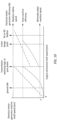
- a motor-generator duty cycle with the 2-speed transmission graph is shown.
- the plots of electrical motor-generator machine shaft speed in revolutions per minute (rpm) are shown graphically in dashed lines.
- the plots for electrical motor-generator efficiency in percentage (%) are shown as dotted lines.
- the graphic along the horizontal X-axis includes a spectrum of engine mechanical shaft speed (rpm) from a zero speed through a ground idle speed, a partial-power speed, a cruise design point speed, an N1 and N2 redline speed and beyond.
- the graphic along the vertical Y-axis includes the motor efficiency from a minimally viable machine speed, to each machine efficiency up to a machine redline speed.
- the graphic demonstrates that the exemplary hybrid electric gas turbine engine two speed transmission for low spool drive 70 during increased motor-generator shaft speeds near ground & flight idle can provide improved power extraction and power injection performance, by enabling improved machine efficiency.
- Another technical advantage provided by the disclosed hybrid electric gas turbine engine two speed transmission for low spool drive can include reduced motor-generator machine volume. As electric machine speed decreases, so does its output voltage. Providing high power at low speed means current must increase. Machine volume is known to increase with current. By raising the machine speed at low engine speed with the two speed transmission, maximum current is decreased, along with required volume.
- Another technical advantage provided by the disclosed hybrid electric gas turbine engine two speed transmission for low spool drive can include a reduction in cable ventilation requirements, due to cooler cables (Joule heating effect - reduced current through the phase cables).
Landscapes
- Engineering & Computer Science (AREA)
- General Engineering & Computer Science (AREA)
- Chemical & Material Sciences (AREA)
- Combustion & Propulsion (AREA)
- Mechanical Engineering (AREA)
- Connection Of Motors, Electrical Generators, Mechanical Devices, And The Like (AREA)
Abstract
A hybrid electric gas turbine engine two speed transmission for a low spool drive including an accessory gearbox in operative communication with a low speed spool motor-generator; a transmission in operative communication with the accessory gearbox and the low speed spool motor-generator; a low speed spool angled gearbox in operative communication with the transmission; and a low speed spool in operative communication with the low speed spool angled gearbox.
Description
- The present disclosure is directed to the improved hybrid electric gas turbine engine two speed transmission for low spool drive.
- Hybrid electric gas turbine engines, in a parallel-hybrid arrangement, require coupling of electric machines referred to as motor-generators MG, to the main shafts of the engine to provide power extraction and power injection, see
Fig. 1 . Typically, this is done by mounting the motor-generators MG to an accessory gearbox AG. In gearbox mounted arrangements, a high spool HS towershaft and low spool LS towershaft are provided to mechanically link the motor-generators MG to the main shafts of the engine. In certain arrangements the machines are directly driven with a fixed gear ratio off the accessory gearbox AG, without a transmission. Therefore, the motor-generators MG are then optimized to the speed ranges of the N1 and N2 spools across idle to redline mechanical shaft speeds. Low spool speed ranges are large, and as a result impose significant design challenges on motor-generator design, and thermal management. - In accordance with the present disclosure, there is provided a hybrid electric gas turbine engine two speed transmission for a low spool drive comprising an accessory gearbox in operative communication with a low speed spool motor-generator; a transmission in operative communication with the accessory gearbox and the low speed spool motor-generator; a low speed spool angled gearbox in operative communication with the transmission; and a low speed spool in operative communication with the low speed spool angled gearbox.
- Particular embodiments further may include at least one, or a plurality of, the following optional features, alone or in combination with each other:
- A further embodiment of any of the foregoing embodiments may additionally and/or alternatively include the accessory gearbox is in operative communication with an oil pump and a fuel pump.
- A further embodiment of any of the foregoing embodiments may additionally and/or alternatively include the accessory gearbox is in operative communication with a first high speed spool motor-generator and a second high speed spool motor-generator.
- A further embodiment of any of the foregoing embodiments may additionally and/or alternatively include the accessory gearbox is in operative communication with a high speed spool via a high speed spool angled gearbox.
- A further embodiment of any of the foregoing embodiments may additionally and/or alternatively include the transmission and low speed spool angled gearbox are integrally formed sharing a common housing.
- A further embodiment of any of the foregoing embodiments may additionally and/or alternatively include the transmission comprises a two speed transmission configured for hybrid electric low spool drive applications.
- A further embodiment of any of the foregoing embodiments may additionally and/or alternatively include the transmission is bolted to the accessory gearbox configured as a line removeable unit.
- In accordance with the present disclosure, there is provided a hybrid electric gas turbine engine two speed transmission for a low spool drive comprising an engine structure proximate a compressor of the gas turbine engine; a low speed spool towershaft coupled to the engine structure; a low speed spool angled gearbox in operative communication with the towershaft and in operative communication with a low speed spool of the gas turbine engine; a transmission in operative communication with the low speed spool angled gearbox; an accessory gearbox in operative communication with the transmission; and a low speed spool motor-generator in operative communication with the accessory gearbox.
- Particular embodiments further may include at least one, or a plurality of, the following optional features, alone or in combination with each other:
- A further embodiment of any of the foregoing embodiments may additionally and/or alternatively include the transmission is bolted to the accessory gearbox configured as a line removeable unit.
- A further embodiment of any of the foregoing embodiments may additionally and/or alternatively include the transmission and low speed spool angled gearbox are integrally formed sharing a common housing.
- A further embodiment of any of the foregoing embodiments may additionally and/or alternatively include the transmission comprises a two speed transmission configured for hybrid electric low spool drive applications.
- A further embodiment of any of the foregoing embodiments may additionally and/or alternatively include the accessory gearbox is in operative communication with a first high speed spool motor-generator and a second high speed spool motor-generator.
- A further embodiment of any of the foregoing embodiments may additionally and/or alternatively include the accessory gearbox is in operative communication with a high speed spool via a high speed spool angled gearbox.
- In accordance with the present disclosure, there is provided a process for a hybrid electric gas turbine engine two speed transmission for a low spool drive comprising: providing an engine structure proximate a compressor of the gas turbine engine; coupling a low speed spool towershaft to the engine structure; coupling a low speed spool angled gearbox in operative communication with the towershaft; coupling the low speed spool angled gearbox in operative communication with a low speed spool of the gas turbine engine; coupling a transmission in operative communication with the low speed spool angled gearbox; coupling an accessory gearbox in operative communication with the transmission; and coupling a low speed spool motor-generator in operative communication with the accessory gearbox.
- Particular embodiments further may include at least one, or a plurality of, the following optional features, alone or in combination with each other:
- A further embodiment of any of the foregoing embodiments may additionally and/or alternatively include the process further comprising integrally forming the transmission and low speed spool angled gearbox sharing a common housing.
- A further embodiment of any of the foregoing embodiments may additionally and/or alternatively include the process further comprising configuring the transmission as a two speed transmission configured for hybrid electric low spool drive applications.
- A further embodiment of any of the foregoing embodiments may additionally and/or alternatively include the process further comprising configuring the two-speed transmission for two operational modes.
- A further embodiment of any of the foregoing embodiments may additionally and/or alternatively include the two operational modes comprises a first
operational MODE 1 configured as a direct drive to the low spool motor-generator for high speed operation of the low speed spool; and a secondoperational MODE 2 configured to provide up to a 3X increase in motor shaft speed wherein the transmission includes a gear ratio of 3.0 which increases motor speed for low speed spool operation selected from the group comprising a ground idle speed and a flight idle speed. - A further embodiment of any of the foregoing embodiments may additionally and/or alternatively include the process further comprising configuring the transmission for a low spool drive power extraction wherein the low spool drive power extraction is arranged for A/C loads and battery recharge.
- A further embodiment of any of the foregoing embodiments may additionally and/or alternatively include the process further comprising configuring the transmission for a low spool drive power injection on ground.
- Other details of the hybrid electric gas turbine engine two speed transmission for fan drive are set forth in the following detailed description and the accompanying drawings wherein like reference numerals depict like elements.
-
Fig. 1 is a schematic representation of a Prior Art turbofan gearbox architecture. -
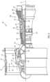
Fig. 2 is a cross section view of an exemplary gas turbine engine. -
Fig. 3 is a schematic representation of a turbofan engine with core mounted gearbox. -
Fig. 4 is a schematic representation of a turbofan engine with fan mounted gearbox. -
Fig. 5 is a schematic representation of an exemplary hybrid electric gas turbine engine two speed transmission for low spool drive. -
Fig. 6 is a schematic representation of an exemplary hybrid electric gas turbine engine two speed transmission for low spool drive. -
Fig. 7 is an isometric view of an exemplary hybrid electric gas turbine engine two speed transmission for low spool drive. -
Fig. 8 is an exemplary process map for flight operation. -
Fig. 9 is an exemplary process map for ground idle operation. -
Fig. 10 is an exemplary motor-generator duty cycle graphic. - The
exemplary engine 20 generally includes alow speed spool 30 and ahigh speed spool 32 mounted for rotation about an engine central longitudinal axis A relative to an enginestatic structure 36 viaseveral bearing systems 38. It should be understood thatvarious bearing systems 38 at various locations may alternatively or additionally be provided, and the location ofbearing systems 38 may be varied as appropriate to the application. - The
low speed spool 30 generally includes aninner shaft 40 that interconnects, a first (or low)pressure compressor 44 and a first (or low)pressure turbine 46. Theinner shaft 40 is connected to thefan 42 through a speed change mechanism, which in the exemplarygas turbine engine 20 is illustrated as a gearedarchitecture 48 to drive thefan 42 at a lower speed than thelow speed spool 30. Theinner shaft 40 may interconnect thelow pressure compressor 44 andlow pressure turbine 46 such that thelow pressure compressor 44 andlow pressure turbine 46 are rotatable at a common speed and in a common direction. In other embodiments, thelow pressure turbine 46 drives both thefan 42 andlow pressure compressor 44 through the gearedarchitecture 48 such that thefan 42 andlow pressure compressor 44 are rotatable at a common speed. Although this application discloses gearedarchitecture 48, its teaching may benefit direct drive engines having no geared architecture. Thehigh speed spool 32 includes anouter shaft 50 that interconnects a second (or high)pressure compressor 52 and a second (or high)pressure turbine 54. Acombustor 56 is arranged in theexemplary gas turbine 20 between thehigh pressure compressor 52 and thehigh pressure turbine 54. Amid-turbine frame 57 of the enginestatic structure 36 may be arranged generally between thehigh pressure turbine 54 and thelow pressure turbine 46. Themid-turbine frame 57 further supports bearingsystems 38 in theturbine section 28. Theinner shaft 40 and theouter shaft 50 are concentric and rotate viabearing systems 38 about the engine central longitudinal axis A which is collinear with their longitudinal axes. - Airflow in the core flow path C is compressed by the
low pressure compressor 44 then thehigh pressure compressor 52, mixed and burned with fuel in thecombustor 56, then expanded through thehigh pressure turbine 54 andlow pressure turbine 46. Themid-turbine frame 57 includesairfoils 59 which are in the core flow path C. Theturbines low speed spool 30 andhigh speed spool 32 in response to the expansion. It will be appreciated that each of the positions of thefan section 22,compressor section 24,combustor section 26,turbine section 28, and low spooldrive gear system 48 may be varied. For example,gear system 48 may be located aft of the low pressure compressor, or aft of thecombustor section 26 or even aft ofturbine section 28, andfan 42 may be positioned forward or aft of the location ofgear system 48. - The
low pressure compressor 44,high pressure compressor 52,high pressure turbine 54 andlow pressure turbine 46 each include one or more stages having a row of rotatable airfoils. Each stage may include a row of static vanes adjacent the rotatable airfoils. The rotatable airfoils and vanes are schematically indicated at 47 and 49. - Referring also to
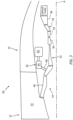
Fig. 3 andFig. 4 , theengine 20 schematic includes different mounting schemes. As seen atFig. 3 , a core mounted scheme includes atowershaft 60 in operative communication with thecompressor section 24. Thetowershaft 60 is in operative communication with anangled gear box 62 that includes bevel gears 64. Amain gearbox 66 is in operative communication with theangled gear box 62.Fig. 4 shows an alternative fan mounted scheme that includes thetowershaft 60 in operative communication with thecompressor section 24. Thetowershaft 60 extends to thefan section 22. Themain gearbox 66 is in operative communication with theangled gear box 62 coupled with thetowershaft 60. In this embodiment, themain gearbox 66 andangled gear box 62 are located in thefan section 22, mounted to thenacelle 15. - Referring also to
Fig. 5 andFig. 6 , showing embodiments of a hybrid electric gas turbine engine two speed transmission forlow spool drive 70. Anaccessory gearbox 72 is in operative communication with exemplary components; anoil pump 74 andfuel pump 76. A first high speed spool N2 motor-generator 78 and a second high speed spool N2 motor-generator 80 are in operative communication with theaccessory gearbox 72. The N2 motor-generators accessory gearbox 72. - An N2 angled
gearbox 82 is in operative communication with theaccessory gearbox 72 viaN2 coupling shaft 84. The N2 angledgearbox 82 is in operative communication with the high speed spool 32 (N2). The N2 motor-generators provide rotary motion energy to thehigh speed spool 32 under predetermined engine operational modes. - An N1 low speed spool motor-
generator 86 is in operative communication with theaccessory gearbox 72. As seen atFig. 5 , a transmission 88 is in operative communication with theaccessory gearbox 72 and driven by the N1 motor-generator 86. The final gear ratio of the N1 motor-generator 86 can be provided within theaccessory gearbox 72. The transmission 88 is also in operative communication with an N1 low speed spool angledgearbox 90. The N1 angledgearbox 90 is in operative communication with the low speed spool 30 (N1) viatowershaft 60. The transmission 88 can be a two-speed transmission. The transmission 88 can be a line removeable unit that is bolted to theaccessory gearbox 72. The transmission 88 can be bolted to the N1 angledgear box 90, with each being separate units as shown inFig. 5 . - Referring also to
Fig. 6 , the transmission 88 and N1 angledgearbox 90 are integrally formed sharing acommon housing 92. Thehousing 92 can be a line removable unit that is bolted to theaccessory gearbox 72. - The transmission 88 comprises a two speed transmission for hybrid electric low spool drive applications. The transmission 88 comprises clutch packs and an epicyclic geartrain configured to reduce the speed range at the low speed spool N1 motor-
generator 86. The transmission 88 is attached to the core-mountedaccessory gearbox 72 and utilizes a lowspeed spool towershaft 94 as an input coupling. The transmission 88 is integrally housed with the N1 angledgearbox 90. N1 angledgearbox 90 includesbevel gears 64 at the input, and anN2 coupling shaft 96 at the output for theaccessory gearbox 72. - Referring also to
Fig. 7 an exemplary hybrid electric gas turbine engine two speed transmission forlow spool drive 70 is shown. The hybrid electric gas turbine engine two speed transmission forlow spool drive 70 is a core mounted scheme with atowershaft 60 in operative communication with thecompressor section 24. The N1 angledgearbox 90 is shown coupled to thetowershaft 60. The transmission 88 is coupled to the N1 angledgearbox 90. The transmission 88 is coupled to theaccessory gearbox 72. Theaccessory gearbox 72 is coupled to the motor-generator 86. - Referring also to
Fig. 8 and Fig. 9 , process maps are shown. Though illustrated as distinct steps, two or more of the steps 100-108 and 112-122 ofFig. 8 and Fig. 9 , respectively, may, in some examples, occur simultaneously. The two-speed transmission 88 is designed for two operational modes and associated gear ratios.Fig. 8 shows a flight idle and adescent operation 98. Theoperational MODE 1 reflects a direct drive to the low spool motor-generator 86 for high N1 speed operation. The aircraft is in operation and begins a descent phase atstep 100. Atstep 102, the engine associated with the aircraft is commanded to a partial-power setting. The partial-power setting can include any setting from flight idle to just below a maximum position of the throttle, power control lever, or the like. At step 104 the transmission is in a direct drive mode, that isoperational MODE 1. Atstep 106 the transmission is set tooperational MODE 2. InMODE 2 thesystem 70 can provide a nominally 3X increase in motor shaft speed. At step 108 the low spool drive power extraction proceeds. The low spool drive power extraction for A/C loads and battery recharge can be accomplished. At this step 108 the low spool drive is in a regenerative braking arrangement. -
Fig. 9 shows a ground idle operation process schematic 110. Thestep 112 includes an engine start typically with the aircraft on the ground. Atstep 114 an engine command to a ground idle setting for the engine. Atstep 116 the transmission is set tooperational MODE 2 which reflects a nominal gear ratio of 3.0 (range from 2.0 to 4.0) which increases motor speed for low N1 speed operation such as ground and flight idle. The transmission 88 reduces the overall N1 speed range at the low spool motor-generator 86. Atstep 118 the low spool drive power extraction can be initiated or a power injection on ground can be initiated. Atstep 120 the transmission can be set tooperational MODE 1, direct drive mode. Atstep 122 the aircraft can begin a takeoff or climb or cruise phase. - Referring also to
Fig. 10 a motor-generator duty cycle with the 2-speed transmission graph is shown. The plots of electrical motor-generator machine shaft speed in revolutions per minute (rpm) are shown graphically in dashed lines. The plots for electrical motor-generator efficiency in percentage (%) are shown as dotted lines. The graphic along the horizontal X-axis includes a spectrum of engine mechanical shaft speed (rpm) from a zero speed through a ground idle speed, a partial-power speed, a cruise design point speed, an N1 and N2 redline speed and beyond. The graphic along the vertical Y-axis includes the motor efficiency from a minimally viable machine speed, to each machine efficiency up to a machine redline speed. The graphic demonstrates that the exemplary hybrid electric gas turbine engine two speed transmission forlow spool drive 70 during increased motor-generator shaft speeds near ground & flight idle can provide improved power extraction and power injection performance, by enabling improved machine efficiency. - A technical advantage provided by the disclosed hybrid electric gas turbine engine two speed transmission for low spool drive can include electrical motor-generator operational optimization.
- Another technical advantage provided by the disclosed hybrid electric gas turbine engine two speed transmission for low spool drive can include reduced motor-generator machine volume. As electric machine speed decreases, so does its output voltage. Providing high power at low speed means current must increase. Machine volume is known to increase with current. By raising the machine speed at low engine speed with the two speed transmission, maximum current is decreased, along with required volume.
- Another technical advantage provided by the disclosed hybrid electric gas turbine engine two speed transmission for low spool drive can include enabling low spool motor-generator optimization to a reduced speed range, enabling smaller machine envelope, reduced machine weight, increased machine thermal efficiency, and reduced torque requirements at low machine speeds.
- Another technical advantage provided by the disclosed hybrid electric gas turbine engine two speed transmission for low spool drive can include a reduction in thermal management system demand, from improved thermal efficiency of the machine.
- Another technical advantage provided by the disclosed hybrid electric gas turbine engine two speed transmission for low spool drive can include a reduction in the weight of support equipment, including power cables and machine speed control units, which can operate with lower maximum current.
- Another technical advantage provided by the disclosed hybrid electric gas turbine engine two speed transmission for low spool drive can include a reduction in cable ventilation requirements, due to cooler cables (Joule heating effect - reduced current through the phase cables).
- Another technical advantage provided by the disclosed hybrid electric gas turbine engine two speed transmission for low spool drive can include an overall weight reduction opportunity estimated at -20 kg including transmission weight.
- There has been provided a hybrid electric gas turbine engine two speed transmission for low spool drive. While the hybrid electric gas turbine engine two speed transmission for low spool drive has been described in the context of specific embodiments thereof, other unenumerated alternatives, modifications, and variations may become apparent to those skilled in the art having read the foregoing description. Accordingly, it is intended to embrace those alternatives, modifications, and variations which fall within the broad-scope of the appended claims.
Claims (15)
- A hybrid electric gas turbine engine two speed transmission for a low spool drive comprising:an accessory gearbox in operative communication with a low speed spool motor-generator;a transmission in operative communication with the accessory gearbox and the low speed spool motor-generator;a low speed spool angled gearbox in operative communication with the transmission; anda low speed spool in operative communication with the low speed spool angled gearbox.
- The hybrid electric gas turbine engine two speed transmission for a low spool drive according to claim 1,wherein the accessory gearbox is in operative communication with an oil pump and a fuel pump; and/orwherein the accessory gearbox is in operative communication with a first high speed spool motor-generator and a second high speed spool motor-generator; and/orwherein the accessory gearbox is in operative communication with a high speed spool via a high speed spool angled gearbox.
- The hybrid electric gas turbine engine two speed transmission for a low spool drive according to claim 1 or 2, wherein the transmission and low speed spool angled gearbox are integrally formed sharing a common housing.
- The hybrid electric gas turbine engine two speed transmission for a low spool drive according to any of claims 1 to 3, wherein the transmission comprises a two speed transmission configured for hybrid electric low spool drive applications.
- The hybrid electric gas turbine engine two speed transmission for a low spool drive according to any of claims 1 to 4, wherein the transmission is bolted to the accessory gearbox configured as a line removeable unit.
- A hybrid electric gas turbine engine two speed transmission for a low spool drive comprising:an engine structure proximate a compressor of the gas turbine engine;a low speed spool towershaft coupled to the engine structure;a low speed spool angled gearbox in operative communication with the towershaft and in operative communication with a low speed spool of the gas turbine engine;a transmission in operative communication with the low speed spool angled gearbox;an accessory gearbox in operative communication with the transmission; anda low speed spool motor-generator in operative communication with the accessory gearbox.
- The hybrid electric gas turbine engine two speed transmission for a low spool drive according to claim 6,wherein the transmission is bolted to the accessory gearbox configured as a line removeable unit; and/orwherein the transmission and low speed spool angled gearbox are integrally formed sharing a common housing; and/orwherein the transmission comprises a two speed transmission configured for hybrid electric low spool drive applications.
- The hybrid electric gas turbine engine two speed transmission for a low spool drive according to claims 6 or 7, wherein the accessory gearbox is in operative communication with a first high speed spool motor-generator and a second high speed spool motor-generator.
- The hybrid electric gas turbine engine two speed transmission for a low spool drive according to any of claims 6 to 8, wherein the accessory gearbox is in operative communication with a high speed spool via a high speed spool angled gearbox.
- A process for a hybrid electric gas turbine engine two speed transmission for a low spool drive comprising:providing an engine structure proximate a compressor of the gas turbine engine;coupling a low speed spool towershaft to the engine structure;coupling a low speed spool angled gearbox in operative communication with the towershaft;coupling the low speed spool angled gearbox in operative communication with a low speed spool of the gas turbine engine;coupling a transmission in operative communication with the low speed spool angled gearbox;coupling an accessory gearbox in operative communication with the transmission; andcoupling a low speed spool motor-generator in operative communication with the accessory gearbox.
- The process of claim 10, further comprising:
integrally forming the transmission and low speed spool angled gearbox sharing a common housing. - The process of claim 10 or 11, further comprising:
configuring the transmission as a two speed transmission configured for hybrid electric low spool drive applications. - The process of claim 12, further comprising:
configuring the two-speed transmission for two operational modes. - The process of any of claims 10 to 13, wherein the two operational modes comprise:a first operational MODE 1 configured as a direct drive to the low spool motor-generator for high speed operation of the low speed spool; anda second operational MODE 2 configured to provide up to a 3X increase in motor shaft speed wherein the transmission includes a gear ratio of 3.0 which increases motor speed for low speed spool operation selected from the group comprising a ground idle speed and a flight idle speed.
- The process of claim any of claims 10 to 14 further comprising:configuring the transmission for a low spool drive power extraction wherein the low spool drive power extraction is arranged for A/C loads and battery recharge; and/orfurther comprising:
configuring the transmission for a low spool drive power injection on ground.
Applications Claiming Priority (1)
| Application Number | Priority Date | Filing Date | Title |
|---|---|---|---|
| US18/404,185 US12540578B2 (en) | 2024-01-04 | 2024-01-04 | Hybrid electric gas turbine engine two speed transmission for low spool drive power injection and power extraction |
Publications (1)
| Publication Number | Publication Date |
|---|---|
| EP4582682A1 true EP4582682A1 (en) | 2025-07-09 |
Family
ID=93925525
Family Applications (1)
| Application Number | Title | Priority Date | Filing Date |
|---|---|---|---|
| EP24221300.7A Pending EP4582682A1 (en) | 2024-01-04 | 2024-12-18 | Hybrid electric gas turbine engine two speed transmission for low spool drive power injection and power extraction |
Country Status (2)
| Country | Link |
|---|---|
| US (1) | US12540578B2 (en) |
| EP (1) | EP4582682A1 (en) |
Families Citing this family (2)
| Publication number | Priority date | Publication date | Assignee | Title |
|---|---|---|---|---|
| US20260063077A1 (en) * | 2024-09-03 | 2026-03-05 | General Electric Company | Gas turbine engine having a mechanical power sharing arrangement |
| US12589878B1 (en) * | 2025-01-24 | 2026-03-31 | Rtx Corporation | Hybrid-electric aircraft propulsion system |
Citations (3)
| Publication number | Priority date | Publication date | Assignee | Title |
|---|---|---|---|---|
| WO2008082335A1 (en) * | 2006-12-29 | 2008-07-10 | Volvo Aero Corporation | A power transmission device for a gas turbine engine |
| US20190218977A1 (en) * | 2018-01-17 | 2019-07-18 | United Technologies Corporation | Systems and methods of low spool power extraction |
| US20200355122A1 (en) * | 2019-05-06 | 2020-11-12 | The Boeing Company | Systems and Methods for Transferring Mechanical Power in a Turbine Engine |
Family Cites Families (7)
| Publication number | Priority date | Publication date | Assignee | Title |
|---|---|---|---|---|
| US7942079B2 (en) | 2007-02-16 | 2011-05-17 | Hamilton Sundstrand Corporation | Multi-speed gearbox for low spool driven auxiliary component |
| GB201219916D0 (en) * | 2012-11-06 | 2012-12-19 | Rolls Royce Plc | An electrical generation arrangement for an aircraft |
| US10336461B2 (en) * | 2016-01-05 | 2019-07-02 | The Boeing Company | Aircraft engine and associated method for driving the fan with the low pressure shaft during taxi operations |
| US10590852B2 (en) | 2017-01-19 | 2020-03-17 | United Technologies Corporation | Gas turbine engine dual towershaft accessory gearbox assembly with a transmission |
| US10422243B2 (en) | 2017-01-19 | 2019-09-24 | United Technologies Corporation | Gas turbine engine dual towershaft accessory gearbox and starter generator assembly |
| US11248523B2 (en) | 2019-11-06 | 2022-02-15 | Raytheon Technologies Corporation | Dual clutch transmission for accessory gearbox drive |
| US11591967B2 (en) * | 2020-12-21 | 2023-02-28 | The Boeing Company | Systems and methods for providing mechanical power to an aircraft accessory with a turbine engine |
-
2024
- 2024-01-04 US US18/404,185 patent/US12540578B2/en active Active
- 2024-12-18 EP EP24221300.7A patent/EP4582682A1/en active Pending
Patent Citations (3)
| Publication number | Priority date | Publication date | Assignee | Title |
|---|---|---|---|---|
| WO2008082335A1 (en) * | 2006-12-29 | 2008-07-10 | Volvo Aero Corporation | A power transmission device for a gas turbine engine |
| US20190218977A1 (en) * | 2018-01-17 | 2019-07-18 | United Technologies Corporation | Systems and methods of low spool power extraction |
| US20200355122A1 (en) * | 2019-05-06 | 2020-11-12 | The Boeing Company | Systems and Methods for Transferring Mechanical Power in a Turbine Engine |
Also Published As
| Publication number | Publication date |
|---|---|
| US20250223925A1 (en) | 2025-07-10 |
| US12540578B2 (en) | 2026-02-03 |
Similar Documents
| Publication | Publication Date | Title |
|---|---|---|
| EP3748146B1 (en) | Hybrid turbofan with differential electrical and mechanical power transfer | |
| EP3667042B1 (en) | Low pressure compressor control for a gas turbine engine | |
| EP4582682A1 (en) | Hybrid electric gas turbine engine two speed transmission for low spool drive power injection and power extraction | |
| US12065973B2 (en) | Electric enhanced transmission for multi-spool load-sharing turbofan engine | |
| US11248532B2 (en) | Hybrid electric dual spool power extraction gearbox | |
| US7882691B2 (en) | High to low pressure spool summing gearbox for accessory power extraction and electric start | |
| EP3987166B1 (en) | Gearbox for boost spool turbine engine | |
| US11686253B2 (en) | Through-flow gas turbine engine with electric motor and electric generator | |
| EP3845750B1 (en) | Spool power extraction via multiple generators | |
| EP2584173B1 (en) | Gas Turbine Engine | |
| US8490410B2 (en) | Axial accessory gearbox | |
| EP3282093A1 (en) | Geared turbofan with low spool power extraction | |
| EP3910174B1 (en) | Reverse-flow gas turbine engine with electric motor | |
| EP2584174A2 (en) | Windmill operation of a gas turbine engine | |
| US20120117982A1 (en) | Axial accessory gearbox | |
| EP3575573B1 (en) | Hybrid amplification of high spool motoring via low spool power extraction and motoring of a differential geared generator | |
| US20140090386A1 (en) | Geared turbofan with fan and core mounted accessory gearboxes | |
| EP2584175B1 (en) | Gas turbine engine and method of operating the same | |
| CN113251111A (en) | Gearbox assembly with electric motor | |
| EP4390063A1 (en) | Exhaust duct for hybrid aircraft powerplant | |
| EP4592514A1 (en) | Constant speed accessory gearbox for turbine engine | |
| EP4553309A1 (en) | Turbine engine accessory system with multiple gearboxes |
Legal Events
| Date | Code | Title | Description |
|---|---|---|---|
| PUAI | Public reference made under article 153(3) epc to a published international application that has entered the european phase |
Free format text: ORIGINAL CODE: 0009012 |
|
| STAA | Information on the status of an ep patent application or granted ep patent |
Free format text: STATUS: THE APPLICATION HAS BEEN PUBLISHED |
|
| AK | Designated contracting states |
Kind code of ref document: A1 Designated state(s): AL AT BE BG CH CY CZ DE DK EE ES FI FR GB GR HR HU IE IS IT LI LT LU LV MC ME MK MT NL NO PL PT RO RS SE SI SK SM TR |
|
| STAA | Information on the status of an ep patent application or granted ep patent |
Free format text: STATUS: REQUEST FOR EXAMINATION WAS MADE |
|
| 17P | Request for examination filed |
Effective date: 20251112 |