EP4582635A1 - Dump assistance system of a loading vehicle, method for dumping a load from a bucket, and a loading vehicle - Google Patents
Dump assistance system of a loading vehicle, method for dumping a load from a bucket, and a loading vehicle Download PDFInfo
- Publication number
- EP4582635A1 EP4582635A1 EP24150288.9A EP24150288A EP4582635A1 EP 4582635 A1 EP4582635 A1 EP 4582635A1 EP 24150288 A EP24150288 A EP 24150288A EP 4582635 A1 EP4582635 A1 EP 4582635A1
- Authority
- EP
- European Patent Office
- Prior art keywords
- bucket
- boom
- dumping
- target height
- lowest point
- Prior art date
- Legal status (The legal status is an assumption and is not a legal conclusion. Google has not performed a legal analysis and makes no representation as to the accuracy of the status listed.)
- Pending
Links
Images




Classifications
-
- E—FIXED CONSTRUCTIONS
- E02—HYDRAULIC ENGINEERING; FOUNDATIONS; SOIL SHIFTING
- E02F—DREDGING; SOIL-SHIFTING
- E02F3/00—Dredgers; Soil-shifting machines
- E02F3/04—Dredgers; Soil-shifting machines mechanically-driven
- E02F3/28—Dredgers; Soil-shifting machines mechanically-driven with digging tools mounted on a dipper- or bucket-arm, i.e. there is either one arm or a pair of arms, e.g. dippers, buckets
- E02F3/36—Component parts
- E02F3/42—Drives for dippers, buckets, dipper-arms or bucket-arms
- E02F3/43—Control of dipper or bucket position; Control of sequence of drive operations
- E02F3/431—Control of dipper or bucket position; Control of sequence of drive operations for bucket-arms, front-end loaders, dumpers or the like
- E02F3/434—Control of dipper or bucket position; Control of sequence of drive operations for bucket-arms, front-end loaders, dumpers or the like providing automatic sequences of movements, e.g. automatic dumping or loading, automatic return-to-dig
-
- E—FIXED CONSTRUCTIONS
- E02—HYDRAULIC ENGINEERING; FOUNDATIONS; SOIL SHIFTING
- E02F—DREDGING; SOIL-SHIFTING
- E02F3/00—Dredgers; Soil-shifting machines
- E02F3/04—Dredgers; Soil-shifting machines mechanically-driven
- E02F3/28—Dredgers; Soil-shifting machines mechanically-driven with digging tools mounted on a dipper- or bucket-arm, i.e. there is either one arm or a pair of arms, e.g. dippers, buckets
- E02F3/36—Component parts
- E02F3/42—Drives for dippers, buckets, dipper-arms or bucket-arms
- E02F3/43—Control of dipper or bucket position; Control of sequence of drive operations
- E02F3/431—Control of dipper or bucket position; Control of sequence of drive operations for bucket-arms, front-end loaders, dumpers or the like
- E02F3/432—Control of dipper or bucket position; Control of sequence of drive operations for bucket-arms, front-end loaders, dumpers or the like for keeping the bucket in a predetermined position or attitude
-
- E—FIXED CONSTRUCTIONS
- E02—HYDRAULIC ENGINEERING; FOUNDATIONS; SOIL SHIFTING
- E02F—DREDGING; SOIL-SHIFTING
- E02F9/00—Component parts of dredgers or soil-shifting machines, not restricted to one of the kinds covered by groups E02F3/00 - E02F7/00
- E02F9/20—Drives; Control devices
- E02F9/2025—Particular purposes of control systems not otherwise provided for
- E02F9/2033—Limiting the movement of frames or implements, e.g. to avoid collision between implements and the cabin
-
- E—FIXED CONSTRUCTIONS
- E02—HYDRAULIC ENGINEERING; FOUNDATIONS; SOIL SHIFTING
- E02F—DREDGING; SOIL-SHIFTING
- E02F9/00—Component parts of dredgers or soil-shifting machines, not restricted to one of the kinds covered by groups E02F3/00 - E02F7/00
- E02F9/26—Indicating devices
- E02F9/264—Sensors and their calibration for indicating the position of the work tool
- E02F9/265—Sensors and their calibration for indicating the position of the work tool with follow-up actions (e.g. control signals sent to actuate the work tool)
Definitions
- the present application relates to a dump assistance system of a loading vehicle, a method for dumping a load from a bucket and a loading vehicle.
- the loading vehicle is provided with a boom and a mining work machine, such as a bucket on the boom.
- a mining work machine such as a bucket on the boom.
- the space for moving the loading machine may be limited and there may be a risk that the boom and the bucket may hit a wall or a roof of the mine or another obstacle during moving the loading vehicle.
- An operator of a loading vehicle may simultaneously actuate an accelerator pedal and control the boom and the bucket for actuating the dumping motion. Controlling the loading vehicle comprising the boom and the bucket may be a demanding task in limited spaces.
- the present invention provides a dump assistance system of a loading vehicle, wherein the loading vehicle comprises
- the advantage of the system is that the dumping motion may be performed more efficiently and safely.
- control unit is configured to lift the boom, when boom lift is triggered manually or automatically, and stop the boom lift motion once the lowest point of the bucket is at the target height.
- control unit is configured to keep the lowest point of the bucket at or above the target height by automatically adjusting the boom angle when the bucket is tilted manually.
- control unit is configured to keep the lowest point of the bucket at the target height or above the target height during the dumping motion.
- the target height TH may be either calculated, measured, or taught manually. It may be calculated or measured by using at least the length of the boom 104, the boom angle, and the bucket angle. Other parameters that may be used for calculating or measuring the target height TH may be for example, the reference point(s) of the bucket 102, i.e. the possible lowest point(s) of the bucket 102, geometry of the bucket 102, swivel arm of the bucket 102, any levers supporting the bucket 102 to the boom 104 or vehicle body 101 and loading vehicle 100 dimension (e.g. height of the boom joint 105). Below are shown some examples of how to calculate the lowest position of the bucket 102.
- the following figures show some embodiments of the dumping assist of the loading vehicle 100 in use.
- the above operation principle applies also to a scenario where the dumping target is on the ground, e.g. a shaft or a crusher, and there is some edge or barrier etc.
- the edge may be raised, i.e. it is extending from the ground upwards.
- Figure 2 shows the bucket 102 in a transport position, i.e. before the dumping operation.
- the reference point i.e. the lowest point of the bucket 102 is the bottom of the bucket and during the dumping motion, the lowest point is the tip of the lip plate 103.
- the dashed line represents the target height TH and the small circles at the dashed line represent positions of the reference point during the dumping operation and show how the reference point is kept at the same level, i.e. at the target height TH, during the dumping operation.
- the lowest point of the bucket may be some other part of the bucket also during the dumping motion.
- Figure 4 shows different bucket 102 positions in a scenario where the dumping target is a shaft, and a barrier 108 is between the shaft and the loading vehicle 100.
- the dumping operation is performed as with the truck, but the target height TH (the lower dashed line) is lower.
- the different positions of the bucket 102 are shown starting from the transport position, in which the bucket 102 is lowest, to the position where the bucket 102 has been tilted for emptying the material from the bucket 102 into the dumping target 107.
- the lowest point of the bucket 102 is kept at the target height TH at the whole time during the dumping motion either by automatically adjusting the boom 104 in response to the manual movement of the bucket 102, or by automatically adjusting the bucket 102 in response to the manual movement of the boom 104.
- FIG 5 shows an embodiment comprising additional safety measures for preventing hitting any obstacles after the dumping motion.
- the lowest point of the bucket 102 i.e. the tip of the lip plate 103
- the bucket 102 would collide with the box or the barrier 108.
- the control unit prevents the loading vehicle 100 from reversing back to the transport position. The reverse motion is only allowed if the lowest point of the bucket 102 is at or above the target height TH and the reverse motion may be performed safely.
- the dump assistance system may comprise a distance sensor or means to measure travelled distance from the transport position (before the dumping operation started) to the position where the dumping motion is performed.
- the distance sensor may determine the distance between the loading vehicle 100 and the dumping target and compare that value to the needed space for lowering the bucket 102 back to the transport position. If the distance between the loading vehicle 100 and the dumping target is less than the length of the bucket 102 and the boom length L1 together in horizontal level, lowering the bucket 102 by lowering the boom 104 is prevented. If the distance is more than the length of the bucket 102 and the boom length L1 together in horizontal level, the bucket 102 may be lowered back to the transport position.
- the travelled distance from the transport position to the position where the dumping motion is performed is measured and the same distance is needed to be reversed after the dumping motion before the bucket 102 may be lowered back to the transport position by lowering the boom 104. If the reversed distance is less than the measured travelling distance before the dumping motion, lowering the bucket 102 and the boom 104 is prevented. This may be done automatically by the control unit.
- Figure 6 shows different scenarios where above-mentioned safety measures may take place.
- the two upper most drawings show scenarios where the reverse motion of the loading vehicle 100 is prevented because the lowest point of the bucket 102 is below the target height TH and reversing would cause a collision with the box.
- the two lowermost drawings show a scenario where the loading vehicle 100 has not reversed enough and the bucket 102 and the boom 104 are still above the dumping target, i.e. the box. Thus, lowering the bucket 102 and the boom 104 is prevented for avoiding the collision.
- FIG. 7 shows another embodiment, wherein the dump assistance system is used for preventing ground collisions.
- the target height TH is the lowest safe position of the bucket 102 where the bucket 102 does not hit the ground.
- the target height TH may be taught by tilting the bucket 102 towards the ground 109 and lowering the bucket 102 to the lowest desired position and storing the target height TH in the control unit.
- the target height TH is calculated by using the boom angle, bucket angle, boom length L1 and the boom joint 105 height as explained above.
- the ground collision may be prevented by keeping the lowest point of the bucket 102 at or above the target height TH. If the lowest point of the bucket 102 is getting close to the target height TH, the speed of the boom or bucket motion downwards may be lowered or stopped.
- the system may comprise several target heights TH. For example, one target height for the dumping motion and reversing after the dumping motion, and one for preventing the ground collision.
- FIG 8 is a simplified illustration of the boom 104.
- the boom 104 comprises a distal end, which is connected to the bucket 102 by a bucket joint 106.
- the proximal end of the boom 104 is rotatably supported by the body 101 of the loading vehicle 100 with boom joint 105.
- the boom angle represents the angle between the horizontal level and the boom axis between the bucket joint 106 and the boom joint 105.
- the boom length L1 is the distance between the bucket joint 106 and the boom joint 105.
- Figure 9 shows a bucket 102 which is rotatably connected to the boom 104 by a bucket joint 106.
- the bucket angle b represents the angle between the horizontal level and the line between the bucket joint 106 and the tip of the lip plate 103.
- the bucket length L2 is the distance between the bucket joint 106 and the tip of the lip plate 103.
- the target height TH may comprise some safety margin added to the lowest point of the bucket 102.
- the safety margin value depends on the situation and may be some millimeters to tens of centimeters.
Landscapes
- Engineering & Computer Science (AREA)
- Mining & Mineral Resources (AREA)
- Civil Engineering (AREA)
- General Engineering & Computer Science (AREA)
- Structural Engineering (AREA)
- Mechanical Engineering (AREA)
- Operation Control Of Excavators (AREA)
Abstract
A dump assistance system of a loading vehicle (100), wherein the loading vehicle comprises
- a body (101),
- a bucket (102),
- a boom (104),
- a control unit (CU) configured to control an action of the loading vehicle,
wherein the loading vehicle is configured to perform a dumping motion, in which the material is removed from the bucket by tilting the bucket,
wherein the dump assistance system comprises target height (TH) data, and the height of the lowest point of the bucket is calculated, measured or taught.
- a body (101),
- a bucket (102),
- a boom (104),
- a control unit (CU) configured to control an action of the loading vehicle,
wherein the loading vehicle is configured to perform a dumping motion, in which the material is removed from the bucket by tilting the bucket,
wherein the dump assistance system comprises target height (TH) data, and the height of the lowest point of the bucket is calculated, measured or taught.
Description
- The present application relates to a dump assistance system of a loading vehicle, a method for dumping a load from a bucket and a loading vehicle.
- In mines and other work sites, various loading vehicles are used. The loading vehicle is provided with a boom and a mining work machine, such as a bucket on the boom. Especially in narrow and low tunnels e.g. in mines and some other kinds of sites, the space for moving the loading machine may be limited and there may be a risk that the boom and the bucket may hit a wall or a roof of the mine or another obstacle during moving the loading vehicle. It may be often difficult for an operator to control the dumping process and move the boom and the bucket to dump a load of the bucket to the dumping target, such as to a box of a dumper truck, in a limited space such as in a mine tunnel. An operator of a loading vehicle may simultaneously actuate an accelerator pedal and control the boom and the bucket for actuating the dumping motion. Controlling the loading vehicle comprising the boom and the bucket may be a demanding task in limited spaces.
- According to a first aspect, the present invention provides a dump assistance system of a loading vehicle, wherein the loading vehicle comprises
- a body,
- a bucket comprising a lip plate and means for measuring a bucket angle,
- a boom having a distal end connected to the bucket, a proximal end rotatably supported by the body with a boom joint, a length, a boom position sensor, and a boom angle,
- a control unit configured to control an action of the loading vehicle,
- wherein the bucket is rotatably connected to the distal end of the boom by a bucket joint, and the bucket has a bucket length between the tip of the lip plate and the bucket joint,
- wherein the loading vehicle is configured to perform a dumping motion, in which the material is removed from the bucket by tilting the bucket,
- wherein the dump assistance system comprises target height data, and
- the height of the lowest point of the bucket is calculated, measured, or taught.
- The advantage of the system is that the dumping motion may be performed more efficiently and safely.
- In an example embodiment of the system, the control unit is configured to lift the boom, when boom lift is triggered manually or automatically, and stop the boom lift motion once the lowest point of the bucket is at the target height.
- In an example embodiment of the system, the control unit is configured to keep the lowest point of the bucket at or above the target height by automatically adjusting the boom angle when the bucket is tilted manually.
- In an example embodiment of the system, the control unit is configured to keep the lowest point of the bucket at or above the target height by automatically tilting the bucket when the boom is moved manually.
- In an example embodiment of the system, the control unit is configured to detect the dumping motion.
- In an example embodiment of the system, the control unit is configured to keep the lowest point of the bucket at the target height or above the target height during the dumping motion.
- In an example embodiment of the system, the control unit is configured to prevent movement of the loading vehicle after dumping motion, if the lowest point of the bucket is below the target height.
- In an example embodiment of the system, the system is configured to measure reversed distance after the dumping motion, wherein control unit is configured to prevent at least one of lowering the boom or tilting the bucket if reverse distance is below pre-stored value.
- In an example embodiment of the system, the lowest point of the bucket is calculated by using at least the boom length, boom angle, bucket height and bucket angle.
- In an example embodiment of the system, a sensor device is provided which is configured to measure a distance between a target and the loading vehicle.
- According to a second aspect, the present invention provides a method for dumping a load from a bucket of a loading vehicle using a dump assistance system according to any one of the preceding claims, comprising steps of:
- defining a target height for the lowest point of the bucket by teaching or calculating,
- triggering a dumping operation,
- moving the lowest point of the bucket to or above the target height,
- driving the loading vehicle to a position, in which the bucket is above a dumping target,
- dumping the load from a bucket while keeping the lowest point of the bucket at or above the target height automatically.
- In an example embodiment of the method, the target height of the lowest position of the bucket is taught prior the dumping operation by moving the bucket by moving the boom manually to a position and storing the bucket position data, and the lifting the lowest point of the bucket to the target height during dumping operation is done automatically.
- In an example embodiment of the method, the lowest point of the bucket is kept at or above the target height by automatically moving the boom in response to the tilting motion of the bucket.
- In an example embodiment of the method, the lowest point of the bucket is kept at or above the target height by automatically tilting the bucket in response to the boom movement.
- In an example embodiment of the method, the lowest point of the bucket is lifted at the target height by tilting the bucket and/or moving the boom automatically when dumping operation is triggered.
- In an example embodiment of the method, the method comprises a further step of triggering an obstacle collision protection after dumping the load, in which
- the lowest point of the bucket is calculated or measured and compared to the target height, and
- reverse motion of the loading vehicle is prevented if the lowest point of the bucket is below the target height.
- In an example embodiment of the method, the method comprises steps for defining lowest position of the bucket for preventing collision to the ground, comprising following steps:
- defining a lowest bucket position above the ground, and
- storing the lowest bucket position to the control unit.
- In an example embodiment of the method, the lowest bucket position is defined by tilting the bucket tip towards the ground and lowering the bucket near the ground by moving the boom downwards.
- In an example embodiment of the method, floor collision protection is enabled after the dumping motion, wherein lowering the bucket below the lowest bucket position is prevented by stopping the boom motion downwards automatically once the lowest bucket position is reached.
- According to a third aspect, the present invention provides a loading vehicle comprising a dump assistance system according to any one previous embodiment.
- It is to be understood that the aspects and embodiments of the invention described above may be used in any combination with each other. Several of the aspects and embodiments may be combined together to form a further embodiment of the invention.
- The accompanying drawings, which are included to provide a further understanding of the invention and constitute a part of this specification, illustrate embodiments of the invention and together with the description help to explain the principles of the invention. In the drawings:
-
Fig. 1a and 1b shows a dump assistance system of a loading vehicle in different positions during the dumping motion, -
Fig. 2 shows the bucket in a transport position, i.e. before the dumping operation and the path of the lowest point of the bucket, -
Fig. 3 shows different positions of the bucket during the dumping operation, -
Fig. 4 shows different positions of the bucket during the dumping operation when the dumping target a shaft, -
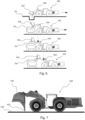
Fig. 5 show the bucket after the dumping motion and situation when the lowest point of the bucket is below the target height, -
Fig. 6 shows different possible scenarios where the bucket or the boom may collide with the dumping target, -
Fig. 7 shows the dump assistance system of a mining vehicle during setting the floor collision protection, -
Fig. 8 shows a simplified version of the boom, -
Fig. 9 shows the bucket, -
Fig. 10 shows examples of the possible lowest points of the bucket, and -
Fig. 11 shows a flowchart of the method for dumping a load from a bucket of a loading vehicle using a dumping assist. - A
loading vehicle 100 is a machine that is used for collecting material into abucket 102 and unloading material from thebucket 102 to a target, such as a box of a truck or other target place, with a dumping motion. Theloading vehicle 100 comprises a body; abucket 102 comprising alip plate 103 and means for measuring a bucket angle; and aboom 104 having a distal end connected to thebucket 102, a proximal end rotatably supported by thebody 101 with aboom joint 105, a boom length L, a boom position sensor, and a boom angle. Thebucket 102 is rotatably connected to the distal end of theboom 104 by a bucket joint 106, and thebucket 102 has a bucket length L2 between the tip of the lip plate and thebucket joint 106. Further, theloading vehicle 100 comprises a control unit, which is configured to control an action of theloading vehicle 100. Theloading vehicle 100 may comprise also other structural elements, such as dog bones and swivel levers or arms for controlling the movement of theboom 104 and/or thebucket 102. - The boom length L1 should be understood as the distance between the bucket joint 106 at the distal end of the and the boom joint 105 at the proximal end of the
boom 104. - The boom angle is an angle between the horizontal level and the
boom 104. - The bucket angle is an angle between the horizontal level and bucket length L2, i.e. the line between the bucket joint 106 and the tip of the
lip plate 103. - A dumping operation is a task of a
loading vehicle 100, in which theloading vehicle 100, being in a transport position, is driven near the dumping target, thebucket 102 is lifted and moved above the dumping target, dumping motion is performed, i.e. thebucket 102 is tilted and the material is removed from thebucket 102, and theloading vehicle 100 is driven back to the transport position. The weight of the material in thebucket 102 may be measured at any time during the dumping operation. - The dump assistance system comprises target height TH data, and the height of the lowest point of the
bucket 102 is calculated or measured. The target height TH is a value of minimum height at which thebucket 102 may move above the target point (dumping target) and perform a dumping motion, i.e. unload the material from thebucket 102 into a dumping target, safely without hitting any obstacles. In other words, the lowest point of thebucket 102 must be at the target height TH or above the target height TH when thebucket 102 is moved above the dumping target, during the dumping motion, and after the dumping motion when theloading vehicle 100 is reversed. - In this disclosure, term calculated is used in several embodiments. It should be understood that calculation includes also measuring, e.g. some dimension(s) or values may not need calculation per se and only measuring is used. Thus, measuring may be used instead of calculating in each embodiment.
- The lowest point, i.e. the reference point, of the
bucket 102 may vary. The lowest point of thebucket 102 may be the tip of thelip plate 103 of thebucket 102, e.g. when thebucket 102 is tilted downwards, i.e. the tip of thelip plate 103 is towards the ground of a mine. Optionally, the lowest point of thebucket 102 is some other point of thebucket 102 between the lip plate and the bucket joint 106 when thebucket 102 is tilted upwards, i.e. the tip of thelip plate 103 is towards the roof of a mine. The lowest point of thebucket 102 may be for example the heel of thebucket 102 or any other point between the heel and the tip of thelip plate 103. - The lowest point of the
bucket 102 is kept at the target height TH or above the target height TH during the dumping motion. For example, theboom 104 may be lowered or lifted, i.e. boom angle is adjusted, automatically by the control unit in response to the manual bucket movement, e.g. whenbucket 102 is tilted, during the dumping motion. Or, thebucket 102 may be lowered or lifted, i.e. the bucket angle is adjusted automatically by the control unit in response to the manual movement of theboom 104 during the dumping motion. In any case the lowest point of thebucket 102 is kept at the same level, i.e. at the target height TH, during the dumping motion. If the lowest point of thebucket 102 is lower than the target height TH, safety measures may be enabled for preventing collision to any obstacles. E.g. the control unit may be configured to prevent movement, e.g. reverse motion of theloading vehicle 100, if the lowest point of thebucket 102 is below the target height TH, or limiting or stopping thebucket 102 and/or boom 104 movement downwards. If the automatic motion of theboom 104 or thebucket 102, depending on which one is controlled by the control unit and which one is controlled manually by the operator, does not response fast enough to the movement of the other, the manual movement of the other may be limited, i.e. reducing speed, or stopped by the control unit. By using the dumping assist, the operator may perform the dumping motion by controlling only one (bucket or boom) motion. The same controlling may be used after the dumping motion when theloading vehicle 100 is reversed back to transport position. - The dump assistance system may be configured to measure reversed distance after the dumping motion and the control unit may be configured to prevent at least one of lowering the
boom 104 or tilting thebucket 102 if reverse distance is below a pre-stored value or measured distance from the transport position to the dumping position (where the bucket is emptied). If the reversed distance is below the pre-stored value or the measured distance from the transport position to the dumping position, lowering theboom 104 orbucket 102 would cause collision with the dumping target, e.g. box of a dump truck. - The target height TH may be either calculated, measured, or taught manually. It may be calculated or measured by using at least the length of the
boom 104, the boom angle, and the bucket angle. Other parameters that may be used for calculating or measuring the target height TH may be for example, the reference point(s) of thebucket 102, i.e. the possible lowest point(s) of thebucket 102, geometry of thebucket 102, swivel arm of thebucket 102, any levers supporting thebucket 102 to theboom 104 orvehicle body 101 andloading vehicle 100 dimension (e.g. height of the boom joint 105). Below are shown some examples of how to calculate the lowest position of thebucket 102. - It should be noted that some of the information that may be needed for calculating the lowest point of the
bucket 102 needs to be known beforehand. For example, the geometry of thebucket 102 is known beforehand and the possible reference points, i.e. the possible lowest points of thebucket 102, are known. They may be for example the tip of thelip plate 103 or the heel, i.e. the back section, of thebucket 102, or any other point between the heel and the tip of thelip plate 103. Also, the geometry of theboom 104 is known beforehand. The boom angle and the bucket angle information may be received from sensors or other means to determine the angle values. The boom angle and the bucket angle are always in relation to the horizontal level. Thus, the angle may be negative if thebucket 102 is tilted downwards, or theboom 104 is pointing downwards. Further, the height of the boom joint and the boom length L1, i.e. the distance between theboom joint 105 and the bucket joint 106, is known or may be measured beforehand. - For defining the target height TH, the lowest point of the
bucket 102 may be used, and additional safety margin may be added to the value. - As noted above, the bucket angle and the boom angle may be used for calculating the lowest point of the
bucket 102 and the target height TH. Thus, the dump assistance system of theloading vehicle 100 comprises means for measuring a bucket angle, which may comprise an angle sensor (e.g. an inclinometer) and/or a linear position sensor (e.g. cylinder sensor). Optionally or additionally, the bucket angle may be calculated by using geometry of theboom 104 and/or thebucket 102. - The boom angle may be determined by using a boom position sensor, such as an angle sensor, which indicates the angle variations of the
boom 104. Optionally, an inclinometer may be used for determining the boom angle. Optionally or additionally, the boom angle may be determined by using position data of a boom cylinder and calculating the angle using the position data of the boom cylinder, locations of the fastening points of the boom cylinder in the boom and/or body, the dimensions of the boom. - The dump assistance system may comprise a sensor device which is configured to measure distance between a target and the
loading vehicle 100. The distance sensor may be for example ultrasonic sensor, infrared (IR) proximity sensor, laser distance sensor, radar sensor or measuring wheel encoder. - Optionally and additionally, the target height TH may be taught by manually driving, i.e. lifting or lowering, the
bucket 102 to the desired position and storing, manually or automatically, the position in the control unit. Once the target height TH is stored, the control unit may automatically adjust the position of thebucket 102 and/or thebucket 102 in response to the movement of the other for keeping the lowest point of thebucket 102 at or above the target height TH during the dumping motion. - The following figures show some embodiments of the dumping assist of the
loading vehicle 100 in use. -
Figure 1a shows aloading vehicle 100 1 wherein abucket 102 has been lifted above the target height TH (the dashed line), theloading vehicle 100 has been driven to a dumping position, i.e. thebucket 102 is above the dumping target, and is ready for dumping the material from thebucket 102. The dumping target in this case is a box of a truck. The dashed line represents the target height TH. The lowest point of thebucket 102 is the tip of thelip plate 103. -
Figure 1b shows thesame loading vehicle 100 as infigure 1a , but the dumping motion has been started and thebucket 102 has been tilted for emptying the material from thebucket 102. The lowest point of thebucket 102, i.e. the tip of thelip plate 103, is kept at the target height TH during the dumping motion. The operator controls either the movement of thebucket 102 or theboom 104 and the control unit adjust the position of the other in response to the manual movement of theboom 104 orbucket 102 for keeping the lowest point of thebucket 102 at the target level. In this case, thebucket 102 has been tilted open, and theboom 104 has been lifted higher, i.e. the boom angle has been increased, for keeping the tip of thelip plate 103 at the target height TH. - The dumping operation has been performed by using a dump assistance system . The first step is to determine the target height TH of the
bucket 102 for safe dumping motion. As noted, this may be done by teaching or calculating. When teaching the target height TH, the operator of theloading vehicle 100 lifts thebucket 102, e.g. lifts theboom 104 andbucket 102, to height that is above the box of the truck. Once the desired height is achieved, the target height TH is stored in the control unit. Another option is to calculate the lowest point of thebucket 102 as explained above and adjust the height of thebucket 102 so that the lowest point of thebucket 102 is at or above the target height TH. Once the desired height for the lowest point of thebucket 102 is calculated, measured or taught, the data may be used during the dumping motion. - The operator triggers the dumping motion, and the
bucket 102 is lifted automatically or manually to the target height TH. Optionally, thebucket 102 is lifted manually, and the movement is stopped once the target height TH is achieved. Once the target height TH is achieved, the operator may drive thebucket 102, i.e. driving theloading vehicle 100 forward, above the dumping target, i.e. the box, and start the dumping motion. The dumping motion may be started even before thebucket 102 is above the dumping target if the operator finds it safe. During the dumping motion, thebucket 102 is tilted downwards, i.e. the tip of lip plate of thebucket 102 is lowered. The control unit is configured to keep the lowest point of thebucket 102 at the target height TH all the time by adjusting theboom 104 position in response to the tilting motion of thebucket 102. The operator controls only thebucket 102 manually. Optionally, the operator adjusts theboom 104 position, i.e. the boom angle, and thebucket 102 is lifted/lowered, i.e. tilted, automatically by the control unit in response to theboom 104 motion for keeping the lowest point of thebucket 102 at the target height TH. In other words, if the lowest point of thebucket 102 starts to go below the target height TH, theboom 104 is lifted automatically to keep the lowest point of thebucket 102 at the target height TH, or the tilt thebucket 102 upwards if theboom 104 is moved too low so that the lowest point of thebucket 102 goes below the target height TH. After the dumping motion, theloading vehicle 100 is reversed back to the transport position and the lowest point of thebucket 102 is kept at the target level until the operator finds it safe to lower thebucket 102. Optionally, the return/reversed motion may be done automatically following the route that was used prior to the dumping motion. - The above operation principle applies also to a scenario where the dumping target is on the ground, e.g. a shaft or a crusher, and there is some edge or barrier etc. The edge may be raised, i.e. it is extending from the ground upwards. Such scenarios are shown in alter figures.
- The target height TH may be taught during each dumping operation, i.e. the previous target height TH may be overridden each time when dumping motion is performed if needed. The target height TH may be taught during the dumping operation so that the
bucket 102 does not need to be lowered after the target height TH is taught, but the operator may continue to perform the dumping motion. -
Figure 2 shows thebucket 102 in a transport position, i.e. before the dumping operation. In the transport position, the reference point, i.e. the lowest point of thebucket 102 is the bottom of the bucket and during the dumping motion, the lowest point is the tip of thelip plate 103. The dashed line represents the target height TH and the small circles at the dashed line represent positions of the reference point during the dumping operation and show how the reference point is kept at the same level, i.e. at the target height TH, during the dumping operation. It should be noted that the lowest point of the bucket may be some other part of the bucket also during the dumping motion. -
Figure 3 shows the different positions of thebucket 102 during the dumping operation starting from the transport position, in which thebucket 102 is lowest, to the position where thebucket 102 has been tilted for emptying the material from thebucket 102 into the dumpingtarget 107. The lowest point of thebucket 102 is kept at the target height TH at the whole time during the dumping motion either by automatically adjusting theboom 104 in response to the manual movement of thebucket 102, or by automatically adjusting thebucket 102 in response to the manual movement of theboom 104. -
Figure 4 showsdifferent bucket 102 positions in a scenario where the dumping target is a shaft, and abarrier 108 is between the shaft and theloading vehicle 100. The dumping operation is performed as with the truck, but the target height TH (the lower dashed line) is lower. The different positions of thebucket 102 are shown starting from the transport position, in which thebucket 102 is lowest, to the position where thebucket 102 has been tilted for emptying the material from thebucket 102 into the dumpingtarget 107. The lowest point of thebucket 102 is kept at the target height TH at the whole time during the dumping motion either by automatically adjusting theboom 104 in response to the manual movement of thebucket 102, or by automatically adjusting thebucket 102 in response to the manual movement of theboom 104. - In
figure 5 shows an embodiment comprising additional safety measures for preventing hitting any obstacles after the dumping motion. After the dumping motion, the lowest point of thebucket 102, i.e. the tip of thelip plate 103, may be lower than the target height TH. If theloading vehicle 100 is reversed, thebucket 102 would collide with the box or thebarrier 108. When the lowest point of thebucket 102 is below the target height TH (dashed line) after dumping motion, the control unit prevents theloading vehicle 100 from reversing back to the transport position. The reverse motion is only allowed if the lowest point of thebucket 102 is at or above the target height TH and the reverse motion may be performed safely. - The dump assistance system may comprise a distance sensor or means to measure travelled distance from the transport position (before the dumping operation started) to the position where the dumping motion is performed. The distance sensor may determine the distance between the
loading vehicle 100 and the dumping target and compare that value to the needed space for lowering thebucket 102 back to the transport position. If the distance between theloading vehicle 100 and the dumping target is less than the length of thebucket 102 and the boom length L1 together in horizontal level, lowering thebucket 102 by lowering theboom 104 is prevented. If the distance is more than the length of thebucket 102 and the boom length L1 together in horizontal level, thebucket 102 may be lowered back to the transport position. Optionally, the travelled distance from the transport position to the position where the dumping motion is performed is measured and the same distance is needed to be reversed after the dumping motion before thebucket 102 may be lowered back to the transport position by lowering theboom 104. If the reversed distance is less than the measured travelling distance before the dumping motion, lowering thebucket 102 and theboom 104 is prevented. This may be done automatically by the control unit. -
Figure 6 shows different scenarios where above-mentioned safety measures may take place. The two upper most drawings show scenarios where the reverse motion of theloading vehicle 100 is prevented because the lowest point of thebucket 102 is below the target height TH and reversing would cause a collision with the box. The two lowermost drawings show a scenario where theloading vehicle 100 has not reversed enough and thebucket 102 and theboom 104 are still above the dumping target, i.e. the box. Thus, lowering thebucket 102 and theboom 104 is prevented for avoiding the collision. -
Figure 7 shows another embodiment, wherein the dump assistance system is used for preventing ground collisions. The target height TH is the lowest safe position of thebucket 102 where thebucket 102 does not hit the ground. The target height TH may be taught by tilting thebucket 102 towards theground 109 and lowering thebucket 102 to the lowest desired position and storing the target height TH in the control unit. Optionally, the target height TH is calculated by using the boom angle, bucket angle, boom length L1 and the boom joint 105 height as explained above. The ground collision may be prevented by keeping the lowest point of thebucket 102 at or above the target height TH. If the lowest point of thebucket 102 is getting close to the target height TH, the speed of the boom or bucket motion downwards may be lowered or stopped. It should be noted that the system may comprise several target heights TH. For example, one target height for the dumping motion and reversing after the dumping motion, and one for preventing the ground collision. -
Figure 8 is a simplified illustration of theboom 104. Theboom 104 comprises a distal end, which is connected to thebucket 102 by abucket joint 106. The proximal end of theboom 104 is rotatably supported by thebody 101 of theloading vehicle 100 withboom joint 105. The boom angle represents the angle between the horizontal level and the boom axis between the bucket joint 106 and theboom joint 105. The boom length L1 is the distance between the bucket joint 106 and theboom joint 105. -
Figure 9 shows abucket 102 which is rotatably connected to theboom 104 by abucket joint 106. The bucket angle b represents the angle between the horizontal level and the line between the bucket joint 106 and the tip of thelip plate 103. The bucket length L2 is the distance between the bucket joint 106 and the tip of thelip plate 103. -
Figure 10 shows examples of the possible lowest points of the bucket. Possible lowest points may be for example, the tip of thebucket 201a, thetop points back points heel 201f. - It should be noted that in each embodiment, the target height TH may comprise some safety margin added to the lowest point of the
bucket 102. The safety margin value depends on the situation and may be some millimeters to tens of centimeters. -
Figure 11 shows a flowchart of the method for dumping a load from a bucket of a loading vehicle using a dumping assist. - Although the invention has been the described in conjunction with a certain type of system, it should be understood that the invention is not limited to any certain type of system. While the present inventions have been described in connection with a number of exemplary embodiments, and implementations, the present inventions are not so limited, but rather cover various modifications, and equivalent arrangements, which fall within the purview of prospective claims.
Claims (20)
- A dump assistance system of a loading vehicle (100), wherein the loading vehicle comprises- a body (101),- a bucket (102) comprising a lip plate (103),- means for measuring a bucket angle (a),- a boom (104) having a distal end connected to the bucket, a proximal end rotatably supported by the body with a boom joint (105), a length (L), a boom position sensor, and a boom angle (b),- a control unit (CU) configured to control an action of the loading vehicle,wherein the bucket is rotatably connected to the distal end of the boom by a bucket joint (106), and the bucket has a bucket length (L2) between the tip of the lip plate and the bucket joint,wherein the loading vehicle is configured to perform a dumping motion, in which the material is removed from the bucket by tilting the bucket,wherein the dump assistance system comprises target height (TH) data, andthe height of the lowest point of the bucket is calculated, measured or taught.
- The dump assistance system according to claim 1, wherein the control unit (CU) is configured to lift the boom, when boom lift is triggered manually or automatically, and stop the boom lift motion once the lowest point of the bucket is at the target height.
- The dump assistance system according to claim 1 or 2, wherein the control unit (CU) is configured to keep the lowest point of the bucket (102) at or above the target height (TH) by automatically adjusting the boom angle (a) when the bucket is tilted manually.
- The dump assistance system according to claim 1 or 2, wherein the control unit (CU) is configured to keep the lowest point of the bucket (102) at or above the target height (TH) by automatically tilting the bucket (102) when the boom is moved manually.
- The dump assistance system according to any one of the preceding claims, wherein the control unit (CU) is configured to detect the dumping motion.
- The dump assistance system according to any one of the preceding claims, wherein the control unit (CU) is configured to keep the lowest point of the bucket at the target height or above the target height during the dumping motion.
- The dump assistance system according to any one of the preceding claims, wherein the control unit (CU) is configured to prevent movement of the loading vehicle after dumping motion, if the lowest point of the bucket is below the target height (TH).
- The dump assistance system according to any one of the preceding claims, wherein the system is configured to measure reversed distance after the dumping motion, wherein control unit (CU) is configured to prevent at least one of lowering the boom or tilting the bucket if reverse distance is below pre-stored value.
- The dump assistance system according to any one of the preceding claims, wherein the target height (TH) is calculated by using at least the boom length (L1), boom angle (a), bucket joint height and bucket angle (b) .
- The dump assistance system according to any one of the preceding claims, comprising a sensor device configured to measure a distance between a target and the loading vehicle.
- A method for dumping a load from a bucket of a loading vehicle using a dump assistance system according to any one of the preceding claims, comprising steps of:- defining a target height for the lowest point of the bucket by teaching or calculating,- triggering a dumping operation,- moving the lowest point of the bucket to or above the target height,- driving the loading vehicle to a position, in which the bucket is above a dumping target,- dumping the load from a bucket while keeping the lowest point of the bucket at or above the target height automatically.
- The method according to claim 11, wherein the target height of the lowest position of the bucket is taught prior the dumping operation by moving the bucket by moving the boom manually to a position and storing the bucket position data, and the lifting the lowest point of the bucket to the target height during dumping operation is done automatically.
- The method according to claim 11 or 12, wherein the lowest point of the bucket is kept at or above the target height by automatically moving the boom in response to the tilting motion of the bucket.
- The method according to claim 11 or 12, wherein the lowest point of the bucket is kept at or above the target height by automatically tilting the bucket in response to the boom movement.
- The method according to any one of claims 11 to 14, wherein the lowest point of the bucket is lifted at the target height by tilting the bucket and/or moving the boom automatically when dumping operation is triggered.
- The method according to any one of claims 11 to 15, comprising a further step of triggering an obstacle collision protection after dumping the load, in which- the lowest point of the bucket is calculated or measured and compared to the target height, and- reverse motion of the loading vehicle is prevented if the lowest point of the bucket is below the target height.
- The method according to any one of claims 11 to 16, comprising steps for defining lowest position of the bucket for preventing collision to the ground, comprising following steps:- defining a lowest bucket position above the ground, and- storing the lowest bucket position to the control unit.
- The method according to claim 17, wherein the lowest bucket position is defined by tilting the bucket tip towards the ground and lowering the bucket near the ground by moving the boom downwards.
- The method according to claim 17 or 18, wherein floor collision protection is enabled after the dumping motion, wherein lowering the bucket below the lowest bucket position is prevented by stopping the boom motion downwards automatically once the lowest bucket position is reached.
- A loading vehicle (100) comprising a dump assistance system according to any one of claims 1 to 10.
Priority Applications (3)
| Application Number | Priority Date | Filing Date | Title |
|---|---|---|---|
| EP24150288.9A EP4582635A1 (en) | 2024-01-04 | 2024-01-04 | Dump assistance system of a loading vehicle, method for dumping a load from a bucket, and a loading vehicle |
| PCT/EP2024/078954 WO2025146261A1 (en) | 2024-01-04 | 2024-10-15 | Dump assistance system of a loading vehicle and method for dumping a load from a bucket |
| AU2024416742A AU2024416742A1 (en) | 2024-01-04 | 2024-10-15 | Dump assistance system of a loading vehicle and method for dumping a load from a bucket |
Applications Claiming Priority (1)
| Application Number | Priority Date | Filing Date | Title |
|---|---|---|---|
| EP24150288.9A EP4582635A1 (en) | 2024-01-04 | 2024-01-04 | Dump assistance system of a loading vehicle, method for dumping a load from a bucket, and a loading vehicle |
Publications (1)
| Publication Number | Publication Date |
|---|---|
| EP4582635A1 true EP4582635A1 (en) | 2025-07-09 |
Family
ID=89474036
Family Applications (1)
| Application Number | Title | Priority Date | Filing Date |
|---|---|---|---|
| EP24150288.9A Pending EP4582635A1 (en) | 2024-01-04 | 2024-01-04 | Dump assistance system of a loading vehicle, method for dumping a load from a bucket, and a loading vehicle |
Country Status (3)
| Country | Link |
|---|---|
| EP (1) | EP4582635A1 (en) |
| AU (1) | AU2024416742A1 (en) |
| WO (1) | WO2025146261A1 (en) |
Citations (3)
| Publication number | Priority date | Publication date | Assignee | Title |
|---|---|---|---|---|
| US20200263385A1 (en) * | 2018-01-31 | 2020-08-20 | Komatsu Ltd. | Loading machine control device and control method |
| EP3751058A1 (en) * | 2018-04-27 | 2020-12-16 | Komatsu Ltd. | Loading machine control device and loading machine control method |
| US20230074375A1 (en) * | 2020-04-17 | 2023-03-09 | Komatsu Ltd. | Control system and control method |
-
2024
- 2024-01-04 EP EP24150288.9A patent/EP4582635A1/en active Pending
- 2024-10-15 AU AU2024416742A patent/AU2024416742A1/en active Pending
- 2024-10-15 WO PCT/EP2024/078954 patent/WO2025146261A1/en active Pending
Patent Citations (3)
| Publication number | Priority date | Publication date | Assignee | Title |
|---|---|---|---|---|
| US20200263385A1 (en) * | 2018-01-31 | 2020-08-20 | Komatsu Ltd. | Loading machine control device and control method |
| EP3751058A1 (en) * | 2018-04-27 | 2020-12-16 | Komatsu Ltd. | Loading machine control device and loading machine control method |
| US20230074375A1 (en) * | 2020-04-17 | 2023-03-09 | Komatsu Ltd. | Control system and control method |
Also Published As
| Publication number | Publication date |
|---|---|
| AU2024416742A1 (en) | 2026-04-23 |
| WO2025146261A1 (en) | 2025-07-10 |
Similar Documents
| Publication | Publication Date | Title |
|---|---|---|
| US8500387B2 (en) | Electronic parallel lift and return to carry or float on a backhoe loader | |
| US7530185B2 (en) | Electronic parallel lift and return to carry on a backhoe loader | |
| US12091840B2 (en) | Work machine | |
| US20100254793A1 (en) | Electronic Anti-Spill | |
| EP3333325A1 (en) | Work vehicle | |
| EP3719223B1 (en) | Work machine and system including work machine | |
| US11933017B2 (en) | Work machine | |
| US11788254B2 (en) | System and method for controlling work machine | |
| US20100215469A1 (en) | Electronic Parallel Lift And Return To Dig On A Backhoe Loader | |
| RU2681800C2 (en) | Excavator handle control system | |
| KR102649042B1 (en) | work vehicle | |
| JP2021042523A (en) | Work machine | |
| US20220381008A1 (en) | Work machine, weighing method, and system including work machine | |
| AU2024416742A1 (en) | Dump assistance system of a loading vehicle and method for dumping a load from a bucket | |
| EP4596793A1 (en) | Method of protecting a loading vehicle from hitting a roof of a mine during a dumping operation | |
| EP4589078A1 (en) | A mobile mining machine, a method for automatically dumping a load, and a control system | |
| CA2689325A1 (en) | Electronic parallel lift and return to carry or float on a backhoe loader | |
| JP7595788B2 (en) | Wheel Loader | |
| US20240360648A1 (en) | Control Device for Wheel Loader | |
| US20250003188A1 (en) | Work machine | |
| JP7786041B2 (en) | Work machinery | |
| JP2022124472A (en) | Loading table lifting device | |
| EP4506508A1 (en) | Work machine, system including work machine, and method for controlling work machine | |
| US12516500B2 (en) | Method and system for controlling work machine, and work machine | |
| JP2024172373A (en) | Work Machine |
Legal Events
| Date | Code | Title | Description |
|---|---|---|---|
| PUAI | Public reference made under article 153(3) epc to a published international application that has entered the european phase |
Free format text: ORIGINAL CODE: 0009012 |
|
| STAA | Information on the status of an ep patent application or granted ep patent |
Free format text: STATUS: THE APPLICATION HAS BEEN PUBLISHED |
|
| AK | Designated contracting states |
Kind code of ref document: A1 Designated state(s): AL AT BE BG CH CY CZ DE DK EE ES FI FR GB GR HR HU IE IS IT LI LT LU LV MC ME MK MT NL NO PL PT RO RS SE SI SK SM TR |
|
| STAA | Information on the status of an ep patent application or granted ep patent |
Free format text: STATUS: REQUEST FOR EXAMINATION WAS MADE |
|
| 17P | Request for examination filed |
Effective date: 20260109 |