EP4582625A1 - Automatic dispensing device, control method, and multi-drum washing machine - Google Patents
Automatic dispensing device, control method, and multi-drum washing machine Download PDFInfo
- Publication number
- EP4582625A1 EP4582625A1 EP23870102.3A EP23870102A EP4582625A1 EP 4582625 A1 EP4582625 A1 EP 4582625A1 EP 23870102 A EP23870102 A EP 23870102A EP 4582625 A1 EP4582625 A1 EP 4582625A1
- Authority
- EP
- European Patent Office
- Prior art keywords
- water
- waterway
- delivery
- water supply
- pipeline
- Prior art date
- Legal status (The legal status is an assumption and is not a legal conclusion. Google has not performed a legal analysis and makes no representation as to the accuracy of the status listed.)
- Pending
Links
Images


Classifications
-
- D—TEXTILES; PAPER
- D06—TREATMENT OF TEXTILES OR THE LIKE; LAUNDERING; FLEXIBLE MATERIALS NOT OTHERWISE PROVIDED FOR
- D06F—LAUNDERING, DRYING, IRONING, PRESSING OR FOLDING TEXTILE ARTICLES
- D06F39/00—Details of washing machines not specific to a single type of machines covered by groups D06F9/00 - D06F27/00
- D06F39/08—Liquid supply or discharge arrangements
- D06F39/088—Liquid supply arrangements
-
- D—TEXTILES; PAPER
- D06—TREATMENT OF TEXTILES OR THE LIKE; LAUNDERING; FLEXIBLE MATERIALS NOT OTHERWISE PROVIDED FOR
- D06F—LAUNDERING, DRYING, IRONING, PRESSING OR FOLDING TEXTILE ARTICLES
- D06F29/00—Combinations of a washing machine with other separate apparatus in a common frame or the like, e.g. with rinsing apparatus
-
- D—TEXTILES; PAPER
- D06—TREATMENT OF TEXTILES OR THE LIKE; LAUNDERING; FLEXIBLE MATERIALS NOT OTHERWISE PROVIDED FOR
- D06F—LAUNDERING, DRYING, IRONING, PRESSING OR FOLDING TEXTILE ARTICLES
- D06F33/00—Control of operations performed in washing machines or washer-dryers
- D06F33/30—Control of washing machines characterised by the purpose or target of the control
- D06F33/32—Control of operational steps, e.g. optimisation or improvement of operational steps depending on the condition of the laundry
- D06F33/37—Control of operational steps, e.g. optimisation or improvement of operational steps depending on the condition of the laundry of metering of detergents or additives
-
- D—TEXTILES; PAPER
- D06—TREATMENT OF TEXTILES OR THE LIKE; LAUNDERING; FLEXIBLE MATERIALS NOT OTHERWISE PROVIDED FOR
- D06F—LAUNDERING, DRYING, IRONING, PRESSING OR FOLDING TEXTILE ARTICLES
- D06F39/00—Details of washing machines not specific to a single type of machines covered by groups D06F9/00 - D06F27/00
- D06F39/02—Devices for adding soap or other washing agents
- D06F39/022—Devices for adding soap or other washing agents in a liquid state
-
- D—TEXTILES; PAPER
- D06—TREATMENT OF TEXTILES OR THE LIKE; LAUNDERING; FLEXIBLE MATERIALS NOT OTHERWISE PROVIDED FOR
- D06F—LAUNDERING, DRYING, IRONING, PRESSING OR FOLDING TEXTILE ARTICLES
- D06F2105/00—Systems or parameters controlled or affected by the control systems of washing machines, washer-dryers or laundry dryers
- D06F2105/02—Water supply
-
- D—TEXTILES; PAPER
- D06—TREATMENT OF TEXTILES OR THE LIKE; LAUNDERING; FLEXIBLE MATERIALS NOT OTHERWISE PROVIDED FOR
- D06F—LAUNDERING, DRYING, IRONING, PRESSING OR FOLDING TEXTILE ARTICLES
- D06F2105/00—Systems or parameters controlled or affected by the control systems of washing machines, washer-dryers or laundry dryers
- D06F2105/06—Recirculation of washing liquids, e.g. by pumps or diverting valves
-
- D—TEXTILES; PAPER
- D06—TREATMENT OF TEXTILES OR THE LIKE; LAUNDERING; FLEXIBLE MATERIALS NOT OTHERWISE PROVIDED FOR
- D06F—LAUNDERING, DRYING, IRONING, PRESSING OR FOLDING TEXTILE ARTICLES
- D06F2105/00—Systems or parameters controlled or affected by the control systems of washing machines, washer-dryers or laundry dryers
- D06F2105/42—Detergent or additive supply
-
- D—TEXTILES; PAPER
- D06—TREATMENT OF TEXTILES OR THE LIKE; LAUNDERING; FLEXIBLE MATERIALS NOT OTHERWISE PROVIDED FOR
- D06F—LAUNDERING, DRYING, IRONING, PRESSING OR FOLDING TEXTILE ARTICLES
- D06F33/00—Control of operations performed in washing machines or washer-dryers
- D06F33/30—Control of washing machines characterised by the purpose or target of the control
-
- D—TEXTILES; PAPER
- D06—TREATMENT OF TEXTILES OR THE LIKE; LAUNDERING; FLEXIBLE MATERIALS NOT OTHERWISE PROVIDED FOR
- D06F—LAUNDERING, DRYING, IRONING, PRESSING OR FOLDING TEXTILE ARTICLES
- D06F39/00—Details of washing machines not specific to a single type of machines covered by groups D06F9/00 - D06F27/00
- D06F39/02—Devices for adding soap or other washing agents
- D06F39/028—Arrangements for selectively supplying water to detergent compartments
Definitions
- the present invention relates to a drum washing machine in the field of household appliances, in particular to a multi-drum washing machine with at least two water drums, and more particularly to an automatic dispensing device applied to the multi-drum washing machine for adding additives in a clothing processing process.
- the additives used in the washing process of traditional washing machines such as detergents, softeners, disinfectants, etc.
- the additives used in the washing process of traditional washing machines are placed separately from the washing machine.
- There is no device for dispensing additives on the washing machine and the additives cannot be automatically dispensed.
- This structure cannot realize the fully automatic washing control process of the washing machine.
- most washing machines are configured to connect the additive box containing detergents and/or softeners with the water inlet pipeline, and the detergents and/or softeners in the additive box are flushed into the water drum through the water inlet.
- this structure requires that the detergents and/or softeners be placed in the additive box first for each washing, and the fully automatic washing control process is also not realized.
- the applicant's previous application provided an automatic dispensing device applicable to a multi-drum washing machine, which directly extracts the additives in the corresponding liquid storage box by using the negative pressure generated by the flowing water, and dispenses the additives into the corresponding drum along with the water flow.
- the additives are extracted from the liquid storage box into the waterway, and the additives in the waterway are dispensed into the corresponding drum by the negative pressure structure provided on the waterway.
- problems such as the small extraction force for the additives in the liquid storage box, resulting in a slow dispensing rate, and inaccurate control during the dispensing process.
- An automatic dispensing device comprising at least two liquid storage boxes 3 containing additives; a delivery waterway 10, wherein the liquid storage boxes 3 are connected to the delivery waterway 10 via a pump 13, and the additives in the corresponding liquid storage boxes 3 are extracted into the delivery waterway 10 by the action of the pump 13; at least two water supply pipelines 2, which can respectively transport incoming water to the outlets of the corresponding water supply pipelines 2.
- the delivery waterway 10 is respectively connected in parallel with each water supply pipeline 2, and the additives extracted by the pump 13 in the delivery waterway 10 are flushed to the outlet of the selected water supply pipeline 2 by the water flow flowing through the selected water supply pipeline 2.
- each water supply pipeline 2 is provided with a suction structure 1, which can generate negative pressure by the water flow passing through the corresponding water supply pipeline 2.
- the suction port 12 of the suction structure 1 is connected with the outlet of the delivery waterway 10, and the additive pumped into the delivery waterway 10 is drawn into the suction structure 1 and transported to the water outlet of the corresponding water supply pipeline 2 along with the water flow.
- each suction structure 1 is connected to the outlet of the delivery waterway 10 via a one-to-one connecting pipe 4, and a one-way valve 8 is provided on the connecting pipe 4 to control the fluid to flow only along the delivery waterway 10 toward the suction structure 1.
- each water supply pipeline 2 is also connected to a flushing pipeline 6, and the inlet of the delivery waterway 10 is connected to each flushing pipeline 6, so that part of the water flow of the water supply pipeline 2 is directly introduced into the delivery waterway 10 to flush the additives in the delivery waterway 10, and then the flushing water containing the additives flows back to the water supply pipeline 2 and flows out through the outlet.
- a one-way valve is provided on the flushing pipeline 6 to ensure that the water in the pipeline flows in a single direction along the water supply pipeline 2 to the delivery waterway.
- control valve for controlling the on/off of water flow in the flushing pipeline 6 is provided.
- each of the flushing pipelines 6 is connected to the inlet of the delivery waterway 10 via the same reversing valve 9, and the reversing valve 9 is used to control each flushing pipeline 6 to be selectively connected to the delivery waterway 10.
- suction structure 1 provided on the water supply pipeline 2 is located at the upstream of where the water supply pipeline (2) connected with the flushing pipeline 6.
- outlets of the liquid storage boxes 3 are connected to the same delivery waterway 10 via corresponding pumps 13, and the pumps 13 pump the additives stored in the corresponding liquid storage boxes 3 into the delivery waterway 10 when they are in operation.
- the pump 13 is integrated with an on-off valve assembly; when the pump 13 is in a non-operating state, the outlet of the liquid storage box 3 is disconnected from the delivery waterway 10, and the additive stored in the liquid storage box 3 can no longer flow into the delivery waterway 10.
- the pump 13 is integrated with a metering component for metering the amount of additive flowing through the pump 13 and pumped from the liquid storage box 3 to the delivery waterway 10.
- the pump 13 is integrated with a one-way valve assembly for limiting the fluid flowing through the pump 13 to flow in only one direction along the liquid storage box 3 to the delivery waterway 10.
- each of the water supply pipelines 2 is connected to a corresponding and different outlet.
- a one-way valve is provided on the water supply pipeline 2 to ensure that the water in the pipeline flows in a single direction from the water inlet end to the water outlet end.
- control valve 7 is provided at the inlet end of the water supply pipeline 2 for controlling the on-off of water flow into the pipeline.
- the suction structure 1 includes a venturi tube 100 provided in the water supply pipeline 2 and capable of generating negative pressure by the flow of water, and the negative pressure area 11 is provided with a suction port 12 connected to the liquid storage box 3 and utilizing negative pressure to extract additives into the water supply pipeline 2.
- both ends of the venturi tube 100 are connected to the corresponding water supply pipeline 2 and are respectively connected to the water inlet and the water outlet.
- the middle part of the venturi tube 100 is provided with a constricted portion with a convexly reduced pipe diameter, and negative pressure is generated at the constricted portion as the water flow velocity suddenly increases to form a negative pressure area 11, and the negative pressure area 11 is provided with a port connected to the outside, and the port constitutes a suction port 12 of the suction structure 1 connected to the waterway 10.
- Another object of the present invention is to provide a control method of the automatic dispensing device.
- the pump 13 corresponding to the selected liquid storage box 3 is turned on, so that the additive in the selected liquid storage box 3 is pumped into the delivery waterway 10.
- the water at the water supply source flows through a selected water supply pipeline 2 to the corresponding outlet, and part of the water flow in the water supply pipeline 2 flows into the delivery waterway 10, flushing the additive in the delivery waterway 10 into the selected water supply pipeline 2, and then flushing it to the outlet of the selected water supply pipeline 2 with the water flow in the water supply pipeline 2.
- the negative pressure generated when the water flows through the suction structure 1 provided on the water supply pipeline 2 is utilized to extract the additives in the delivery waterway 10, and the additives enter the selected water supply pipeline 2 through the suction port 12, and then are flushed to the water outlet of the selected water supply pipeline 2 along with the water flow in the water supply pipeline 2.
- the water outlet end of the waterway 10 is connected to the suction port 12 of the suction structure 1 provided on the selected water supply pipeline 2.
- the negative pressure generated by the suction structure 1 is used to return the flushing water after flushing the waterway 10 through the flushing pipeline 6 from the suction port 12 to the selected water supply pipeline 2, and flows out through the water outlet of the water supply pipeline 2 along with the water flow.
- the above-mentioned automatic dispensing device is installed on a multi-drum washing machine, so that multiple water drums of the multi-drum washing machine can share a set of additive dispensing system, thereby achieving the purpose of controllably dispensing additives into a selected water drum along with the incoming water flow.
- the pump provides power to draw the additive from the liquid storage box into the delivery waterway
- the suction structure provides driving force for the additive in the delivery waterway to flow toward the water drum, thereby achieving the effect of different power components driving the additives at different stages in steps, thereby greatly improving the accuracy of dispensing control.
- the additive is driven by a two-stage power component, so that the flow rate of the additive during the delivery process can be significantly increased, thereby greatly improving the delivery efficiency.
- the pump and the water supply delivery waterway can be executed together, so that the additives are extracted from the liquid storage box into the delivery waterway, and the additives in the delivery waterway are flushed and released into the water drum by the water flow can be run synchronously.
- the time consumption of dispensing is greatly reduced and the speed is significantly improved.
- the invention has a simple structure, significant effects and is suitable for popularization and use.
- First liquid extraction pipeline 102, second venturi tube; 22, second water supply pipeline; 32, second liquid storage box; 42, second connecting pipeline; 52, second water drum; 62, second flushing pipeline; 72, second control valve; 82, second one-way valve; 122, second suction port; 132, second pump; 142, second liquid extraction pipeline.
- an embodiment of the present invention introduces a multi-drum washing machine, which includes a plurality of water drums 5 independently arranged, and each water drum 5 can process clothes respectively.
- the washing machine is provided with a water inlet structure 15 for introducing external water flow into the washing machine; the washing machine is also provided with an automatic dispensing device, which delivers additives along with the water flow flowing into the water inlet structure into the corresponding water drum 5, so as to use the additives delivered along with the water flow to process the clothes in the corresponding water drum 5.
- the additives include but are not limited to the following types: detergents, softeners, disinfectants, fragrances, bleaches, etc.
- an automatic dispensing device is also introduced in an embodiment of the present invention.
- the automatic dispensing device can be applied to the above-mentioned multi-drum washing machine to dispense additives into the corresponding water drum 5 of the washing machine; it can also be applied to any existing equipment to dispense corresponding additives into any waterway in the equipment.
- the automatic dispensing device described in the embodiment of the present invention includes a liquid storage box 3, which contains additives used for treating clothes; at least two water supply pipelines 2, the water inlet end of each water supply pipeline 2 is connected to the same water supply source, and the water supply source is the water inlet structure 15 of the washing machine.
- Each water supply pipeline 2 has different and corresponding water outlets connected to each other, so that each water supply pipeline 2 can transport the incoming water to the water outlet of the corresponding pipeline.
- a delivery waterway 10 the liquid storage box 3 is connected to the delivery waterway 10 through a pump 13, and the additives in the corresponding liquid storage box 3 are extracted into the delivery waterway 10 through the action of the pump 13.
- the delivery waterway 10 is connected in parallel with each water supply pipeline 2, and the additives extracted by the pump 13 in the delivery waterway 10 are flushed to the water outlet of the selected water supply pipeline 2 by the water flow flowing through the selected water supply pipeline 2.
- the water outlets of each water supply pipeline 2 of the automatic dispensing device are connected to each water drum 5 of the washing machine in a one-to-one correspondence, and the water supply source is provided by the washing machine water inlet structure 15, so that in the process of washing water entering the corresponding water drum 5 of the multi-drum washing machine, the additives are put into the corresponding water drum 5 together with the inlet water flow.
- the number of water outlets of the automatic dispensing device and the number of water drums can also be set to be different, so that at least one water drum corresponds to multiple water outlets, or at least one water outlet corresponds to multiple water drums.
- the automatic dispensing device can extract additives from different liquid storage boxes into the delivery waterway through the pump, and use the water flow flowing through the corresponding water supply pipeline to dispense the extracted additives in the parallel delivery waterway to the corresponding water outlet along with the water flow, thereby achieving the purpose of dispensing additives in the same liquid storage box to multiple locations respectively through a set of system.
- the above automatic dispensing device is installed on a multi-drum washing machine, so that multiple water drums of the multi-drum washing machine can share a set of additive dispensing system, thereby achieving the purpose of controllably dispensing additives into a selected water drum along with the incoming water flow.
- the automatic dispensing device described in the embodiment of the present invention includes at least two liquid storage boxes 3, each of which can store additives of different categories and/or different concentrations. Of course, the same additives can also be stored in some of the liquid storage boxes 3, so that one or more of the liquid storage boxes 3 can be used as a backup.
- Each liquid storage box 3 is connected to the delivery waterway 10 through different liquid extraction pipelines 14; each liquid extraction pipeline 14 is provided with a pump 13, which is used to extract the additives in different liquid storage boxes 3 into the delivery waterway 10, thereby realizing that different drums of the washing machine share a set of liquid storage boxes 3, so that various additives in a set of liquid storage boxes 3 can be controlled to be dispensed into different water drums 5.
- this embodiment introduces an automatic dispensing device, including a liquid storage box 3, which contains additives used for treating clothes; at least two water supply pipelines 2, the water inlet of each water supply pipeline 2 is respectively connected to the water inlet structure 15 of the multi-drum washing machine, and the water outlet of each water supply pipeline 2 is respectively connected to different, one-to-one corresponding water drums 5, so that each water supply pipeline 2 can transport the washing machine water to the corresponding water drum 5, so as to achieve the purpose of supplying washing water to any water drum 5 of the multi-drum washing machine.
- Each water supply pipeline 2 is provided with a suction structure 1, which can generate negative pressure through the water flow flowing through the corresponding water supply pipeline 2; the suction port 12 of the suction structure 1 is connected to the water outlet of the delivery waterway 10 through the connecting pipeline 4, so that the additives extracted from the delivery waterway 10 can be sucked into the suction structure 1, and the additives are dispensed into the corresponding washing machine water drum 5 along with the water flow.
- the water outlets of the automatic dispensing device are connected to the water drums 5 of the washing machine in a one-to-one correspondence, and the water supply source is provided by the water inlet structure 15 of the washing machine, so that in the process of washing water entering the corresponding water drum 5 of the multi-drum washing machine, the additives are dispensed into the corresponding water drum 5 together with the inlet water flow, so as to achieve the purpose of automatically dispensing the additives into the corresponding water drum 5 along with the inlet water flow.
- the suction structure 1 includes a venturi tube 100 provided in the water supply pipeline 2, which can generate negative pressure by the flow of water.
- the negative pressure area 11 of the venturi tube 100 is provided with a suction port 12 connected to the delivery waterway 10 and uses negative pressure to extract additives into the water supply pipeline 2.
- both ends of the venturi tube 100 are connected to the water supply pipeline 2 and are respectively connected to the water inlet and the water outlet; the middle part of the venturi tube 100 is provided with a closing part in which the diameter of the pipe in the pipeline is convexly reduced.
- the closing part Due to the sudden decrease in the inner diameter of the pipe wall of the closing part, the water flow velocity in this area suddenly increases, so that the closing part forms a negative pressure area 11 that generates negative pressure as the water flows, and the negative pressure area 11 is provided with a port connected to the outside, and the port constitutes the suction port 12 of the suction structure 1 connected to the delivery waterway 10 through the connecting pipeline 4.
- the suction structure 1 can be directly composed of a venturi tube 100 that generates a negative pressure suction effect according to changes in the water flow rate, thereby achieving the purpose of pumping the stored additives in the delivery waterway 10 into the inlet water flow of the corresponding water supply pipeline 2 along with the inlet water flow, thereby achieving the purpose of putting the additives into the water drum of the washing machine.
- each water supply pipeline 2 is respectively connected to a corresponding, different water drum 5.
- a one-way valve 8 (not indicated in the attached figure) is provided on the water supply pipeline 2 to ensure that the water in the pipeline flows in a single direction from the water inlet source end to the water outlet end.
- the automatic dispensing device is fed with water through different water supply waterways to achieve the purpose of feeding water and delivering additives into different water drums respectively.
- a control valve 7 is provided at the water inlet end of the water supply pipeline 2 to control the on-off of the water flow of the water supply pipeline 2.
- the control valve 7 is provided at the upstream part of the suction structure 1 to achieve on-off control of the water inlet at the suction structure 1.
- the automatic dispensing device further includes a flushing pipeline 6, the water inlet end of the flushing pipeline 6 is connected to partially of the water supply pipeline 2 at the downstream of the venturi tube 100, and the water outlet end of the flushing pipeline 6 is connected to the water inlet of the delivery waterway 10; the other end of the delivery waterway 10 is a water outlet, which is connected to the suction port 12 of the suction structure 1 through the connecting pipeline 4.
- the water flow at the water outlet end of the water supply pipeline 2 is directly introduced into the delivery waterway 10, and then circulated back to the water supply pipeline 2 through the suction structure 1, and the delivery waterway 10 is flushed with circulating water, so that the additives pumped into the delivery waterway 10 by the pump 13 are all flushed into the water supply pipeline 2, and the additives remaining in the pipeline can be flushed, so as to ensure that the additives pumped into the delivery waterway 10 by the pump 13 of the automatic dispensing device can be completely discharged into the water supply pipeline 2 with the water flow.
- the purpose of flushing the automatic dispensing device and preventing the residual additives from affecting the subsequent use of the device can also be achieved.
- a one-way valve 8 can be provided on the flushing pipeline 6 and/or the connecting pipeline 4 to ensure that the water in the pipeline flows in a single direction from the water inlet end to the water outlet end.
- a one-way valve 8 is provided on the connecting pipeline 4. The one-way valve 8 is used to ensure that the liquid in the connecting pipeline 4 flows only in a single direction from the delivery waterway 10 to the water supply pipeline 2 to avoid backflow.
- a control valve 7 for controlling the water flow in the flushing pipeline 6 and/or the connecting pipeline 4 is provided to control the flow of flushing water from the water supply pipeline 2 to the delivery waterway 10 (not indicated in the drawings).
- each water supply pipeline 2 is connected to a flushing pipeline 6, and the water outlet end of each flushing pipeline 6 is connected to the same reversing valve 9.
- the reversing valve 9 is also connected to the water inlet of the delivery waterway 10, so that under the control of the reversing valve 9, each flushing pipeline 6 can be selectively connected to the water inlet of the delivery waterway 10.
- the automatic dispensing device comprises at least two liquid storage boxes 3, and different types of additives are added to each liquid storage box 3, so that the automatic dispensing device can classify and automatically dispense different types of additives.
- the water inlet end of the first water supply pipeline 21 is provided with a first venturi tube 101, and the water outlet end is connected to the first water drum 51.
- the water inlet end of the second water supply pipeline 22 is provided with a second venturi tube 102, and the water outlet end is connected to the second water drum 52.
- the water outlet ends of the first water supply pipeline 21 and the second water supply pipeline 22 are respectively provided with ports, and the two ports are respectively connected to the water inlet end of a flushing pipeline 6.
- the water outlet ends of the two flushing pipelines 6 are connected to the same reversing valve 9, and the reversing valve 9 has two inlets and one outlet, and the two inlets are respectively connected to the water outlet ends of the first flushing pipeline 61 and the second flushing pipeline 62, and the outlet is connected to the water inlet of the delivery waterway 10.
- the reversing valve 9 has two states, which communicate one of the two inlets with the outlet, so as to realize that the first flushing pipeline 61 and the second flushing pipeline 62 are respectively communicated with the delivery waterway 10.
- the water outlet of the delivery waterway 10 is connected to the first suction port 121 of the first venturi tube 101 through the first connecting pipeline 41 provided with the first one-way valve 81, and is connected to the second suction port 122 of the second venturi tube 102 through the second connecting pipeline 42 provided with the second one-way valve 82.
- one-way valves 8 are respectively installed on the two connecting pipelines 4, so that the one-way valves 8 are used to control the flow direction of the liquid in the pipeline, so as to ensure that the liquid in the pipeline always flows in a single direction toward the side of the venturi tube 100, thereby preventing the water flow in the water supply pipeline 2 from directly flowing from the connecting pipeline 4 into the delivery waterway 10.
- the first liquid storage box 31 is connected to the delivery waterway 10 via a first liquid extraction pipeline 141 provided with a first pump 131
- the second liquid storage box 32 is connected to the delivery waterway 10 via a second liquid extraction pipeline 142 provided with a second pump 132.
- a one-way valve 8 can be installed on the liquid extraction pipeline 14 provided with the pump 13, and the pump 13 can be directly integrated with a one-way valve assembly, or a one-way valve assembly can be integrated and installed at the liquid outlet of the liquid storage box 3, etc., so as to prevent the liquid from flowing back into the liquid storage box.
- the automatic dispensing device When the additive A in the first liquid storage box 31 is added into the first water drum 51, the automatic dispensing device is in the following state: As shown in Figure 2 , the outlet of the reversing valve 9 is connected to the first inlet and disconnected from the second inlet, the first pump 131 is working, the second pump 132 is not working, the first control valve 71 is opened, and the second control valve 72 is closed. At this time, the delivery waterway 10 connects the first connecting pipeline 41 and the first flushing pipeline 61, and the additive A in the first liquid storage box 31 is acted upon by the first pump 131 and pumped into the delivery waterway 10 through the first liquid extraction pipeline 141.
- the water flow in the first water supply pipeline 21 flows through the first venturi tube 101, and the first venturi tube 101 draws the additive A pumped in the delivery waterway 10 into the first water supply pipeline 21, and flows into the first water drum 51 along with the water flow in the first water supply pipeline 21.
- part of the incoming water flow in the first water supply pipeline 21 enters the delivery waterway 10 to flush the delivery waterway 10.
- the flushing water then flows back into the first water supply pipeline 21 through the first venturi tube 101 and flows into the first water drum 51 from the water outlet together with the incoming water flow.
- the automatic dispensing device When the additive B in the second liquid storage box 32 is added into the first water drum 51, the automatic dispensing device is in the following operating state: As shown in Figure 3 , the outlet of the reversing valve 9 is connected to the first inlet and disconnected from the second inlet, the first pump 131 is not working, the second pump 132 is working, the first control valve 71 is opened, and the second control valve 72 is closed. At this time, the delivery waterway 10 connects the first connecting pipeline 41 and the first flushing pipeline 61, and the additive B in the second liquid storage box 32 is acted upon by the second pump 132 and pumped into the delivery waterway 10 through the second liquid extraction pipeline 142.
- the water flow in the first water supply pipeline 21 flows through the first venturi tube 101, and the first venturi tube 101 draws the additive B pumped in the delivery waterway 10 into the first water supply pipeline 21, and flows into the first water drum 51 along with the water flow in the first water supply pipeline 21.
- part of the incoming water flow in the first water supply pipeline 21 enters the delivery waterway 10 to flush the delivery waterway 10.
- the flushing water then flows back into the first water supply pipeline 21 through the first venturi tube 101 and flows into the first water drum 51 from the water outlet together with the incoming water flow.
- the automatic dispensing device When the additive A in the first liquid storage box 31 is added into the second water drum 52, the automatic dispensing device is in the following operating state: As shown in Figure 4 , the outlet of the reversing valve 9 is disconnected from the first inlet and connected to the second inlet, the first pump 131 is working and the second pump 132 is not working, the first control valve 71 is closed and the second control valve 72 is opened. At this time, the delivery waterway 10 connects the second connecting pipeline 42 and the second flushing pipeline 62, and the additive A in the first liquid storage box 31 is pumped into the delivery waterway 10 by the first pump 131. The water flow in the second water supply pipeline 22 flows through the second venturi tube 102.
- the second venturi tube 102 draws the additive A pumped in the delivery waterway 10 into the second water supply pipeline 22, and flows into the second water drum 52 along with the water flow in the second water supply pipeline 22. At the same time, part of the incoming water flow in the second water supply pipeline 22 enters the delivery waterway 10 to flush the delivery waterway 10. The flushing water then flows back into the second water supply pipeline 22 through the second venturi tube 102 and flows into the second water drum 52 from the water outlet together with the incoming water flow.
- the automatic dispensing device When the additive B in the second liquid storage box 32 is added into the second water drum 52, the automatic dispensing device is in the following operating state: As shown in Figure 5 , the outlet of the reversing valve 9 is disconnected from the first inlet and connected to the second inlet, the first pump 131 is not working, the second pump 132 is working, the first control valve 71 is closed, and the second control valve 72 is opened. At this time, the delivery waterway 10 connects the second connecting pipeline 42 and the second flushing pipeline 62, and the additive B in the second liquid storage box 32 is pumped into the delivery waterway 10 by the second pump 132. The water flow in the second water supply pipeline 22 flows through the second venturi tube 102.
- the second venturi tube 102 draws the additive B pumped in the delivery waterway 10 into the second water supply pipeline 22, and flows into the second water drum 52 along with the water flow in the second water supply pipeline 22. At the same time, part of the incoming water flow in the second water supply pipeline 22 enters the delivery waterway 10 to flush the delivery waterway 10. The flushing water then flows back into the second water supply pipeline 22 through the second venturi tube 102 and flows into the second water drum 52 from the water outlet together with the incoming water flow.
- a labyrinth flow path can also be set on the delivery waterway 10.
- the labyrinth flow path is composed of a waterway that is coiled and spirally arranged to extend the axial length of the pipeline.
- the labyrinth flow path is located at one end of the delivery waterway 10 connected to the connecting pipeline 4, and the labyrinth flow path is located at the downstream of the place where each liquid storage box 3 is connected to the delivery waterway 10 through the pump 13, so that the water inlet end of the labyrinth flow path is connected to the liquid storage boxes 3 at upstream, and the water outlet end is respectively connected to the inlet of each connecting pipeline 4 (not indicated in the drawings).
- a metering device for detecting the flow rate of the liquid flowing through is provided on the connecting pipe 4 between the labyrinth flow path and the suction port 12 of the suction structure.
- the metering component can also be directly integrated on the pump 13, so that the pump 13 itself is a metering pump, and the parameters of the pump 13 are used to directly measure and count the dosage of the additive.
- the pump 13 can be any existing metering pump with a metering function, for example: a metering pump that indirectly obtains the dosage by counting any parameter such as the number of revolutions of the impeller in the pump, the speed, time, power, etc.
- This embodiment also introduces a control method applied to the above-mentioned automatic dispensing device.
- the pump 13 corresponding to the selected liquid storage box 3 is turned on, so that the additive in the selected liquid storage box 3 is pumped into the delivery waterway 10.
- Water at the water supply source flows through a selected water supply pipeline 2 to the corresponding water outlet, and part of the water flow in the water supply pipeline 2 flows into the delivery waterway 10, flushing the additive in the delivery waterway 10 into the selected water supply pipeline 2, and then flushing it to the outlet of the selected water supply pipeline 2 with the water flow in the water supply pipeline 2.
- the steps of pumping the additive in the liquid storage box 3 into the delivery waterway 10 via the pump 13 and introducing water into the water supply pipe 2 to flush the additive in the delivery waterway 10 into the water drum 5 can be performed simultaneously.
- the steps of pumping the additive in the liquid storage box 3 into the delivery waterway 10 via the pump 13 and introducing water into the water supply pipe 2 to flush the additive in the delivery waterway 10 into the water drum 5 can be performed alternately.
- control method of the present invention has more diverse delivery methods and can realize different delivery logics compared to the limited technology.
- the steps of pumping the additive in the liquid storage box into the delivery waterway through the pump and flushing the additive in the delivery waterway into the water drum can be executed simultaneously, making the delivery process more concise and time-saving.
- the negative pressure generated when the water flows through the suction structure 1 provided on the water supply pipeline 2 is used to extract the additive in the delivery waterway 10, and enter the corresponding water supply pipeline 2 through the suction port 12, and then rush to the outlet of the selected water supply pipeline 2 with the water flow in the water supply pipeline 2.
- the additive is injected into the delivery waterway with power provided by the pump, and the additive is dispensed into the drum with power provided by the suction structure provided on the delivery waterway, thereby increasing the flow rate of the additive and further improving the dispensing reaction efficiency.
- the flushing pipeline 6 connected to the water supply pipeline 2 is selected to be connected to the delivery waterway 10, and the liquid storage box 3 is disconnected from the delivery waterway 10.
- the flushing water containing the additive then flows back into the water supply pipeline 2 to ensure that the circulating flushing water can be used to completely flush the additive in the delivery waterway 10 during the additive delivery process, thereby achieving the effect of preventing the residual of the additive in the delivery waterway.
- the water outlet end of the delivery waterway 10 is connected to the suction port 12 of the suction structure 1 provided on the selected water supply pipeline 2, so that after the delivery waterway 10 is flushed through the flushing pipeline 6, the flushing water that flows back from the suction port 12 to the selected water supply pipeline 2 can flow out through the water outlet of the selected water supply pipeline 2, thereby switching the water supply to the two water supply pipelines 2, and achieving the effect of respectively putting additives into different water drums 5, thereby improving the diversity of additive placement.
- the water inlet structure 15 of the washing machine intakes water into the corresponding water drum 5 through the selected water supply pipeline 2, part of the intake water flow will flow through the delivery waterway 10, and part of the water flow will flush the delivery waterway 10, so that the water supply pipeline 2 intakes water into the water drum 5 and the flushing of the delivery waterway 10 can be performed simultaneously.
- the automatic dispensing device can dispense different types of additives stored in each liquid storage box 3 respectively.
- the automatic dispensing device dispenses additives
- one of the suction ports 12 is connected to the delivery waterway 10
- one of the pumps 13 corresponding to each liquid storage box 3 is turned on, so that the corresponding liquid storage box 3 is connected to the water supply pipeline 10, and the additive pump 13 stored in the corresponding liquid storage box 3 is dispensed to the delivery waterway 10, and is flushed into the corresponding water supply pipeline 2 with the inlet water flow under the action of the suction structure 1, and enters the corresponding water drum 5 with the water flow in the water supply pipeline 2.
- the following is an example of a multi-drum washing machine with two water drums 5, namely the first water drum 51 and the second water drum 52; and two liquid storage boxes 3, namely the first liquid storage box 31 and the second liquid storage box 32.
- the specific control method is as follows: When the additive A stored in the first liquid storage box 31 is added into the first water drum 51.
- the first water supply pipeline 21 of the automatic dispensing device intakes water into the first water drum 51.
- the first pump 131 connected to the outlet of the first liquid storage box 31 is turned on, and the first pump 131 pumps the additive A stored in the first liquid storage box 31 to the delivery waterway 10.
- negative pressure is generated, and the additive A in the delivery waterway 10 is sucked into the first water supply pipeline 21 by the negative pressure, and flushed into the first water drum 51 along with the incoming water flow.
- part of the water in the first water supply pipeline 21 flows through the first flushing pipeline 61, the delivery waterway 10, and the first connecting pipeline 41 into the first venturi tube 101, so as to flush the residual additive A in the suction structure 1 and the delivery waterway 10, so that the additive A pumped to the delivery waterway 10 by the first pump 131 is completely flushed into the first water drum 51 along with the flushing water flow.
- the second water supply pipeline 22 of the automatic dispensing device flows into the second water drum 52.
- the first pump 131 provided at the outlet of the first liquid storage box 31 is turned on, and the first pump 131 pumps the additive A stored in the first liquid storage box 31 to the delivery waterway 10.
- Negative pressure is generated when the second water supply pipeline 22 flows through the second venturi tube 102, and the additive A in the delivery waterway 10 is sucked into the second water supply pipeline 22 by the negative pressure, and flushed into the second water drum 52 along with the incoming water flow.
- part of the water in the second water supply pipeline 22 flows through the second flushing pipeline 62, the delivery waterway 10, and the second connecting pipeline 42 into the second venturi tube 102, so as to flush the residual additive A in the suction structure 1 and the delivery waterway 10, so that the additive A pumped to the delivery waterway 10 by the first pump 131 is completely flushed into the second water drum 52 along with the flushing water flow.
- the first water supply pipeline 21 of the automatic dispensing device intakes water into the first water drum 51.
- the second pump 132 provided at the outlet of the second liquid storage box 32 is turned on, and the second pump 132 pumps the additive B stored in the second liquid storage box 32 to the delivery waterway 10.
- Negative pressure is generated when the water in the first water supply pipeline 21 flows through the first venturi tube 101, and the additive B in the delivery waterway 10 is sucked into the first water supply pipeline 21 by the negative pressure, and flushed into the first water drum 51 along with the inflowing water flow.
- part of the water in the first water supply pipeline 21 flows through the first flushing pipeline 61, the delivery waterway 10, and the first connecting pipeline 41 into the first venturi tube 101, so as to flush the residual additive B in the suction structure 1 and the delivery waterway 10, so that the additive B pumped into the delivery waterway 10 by the second pump 132 is completely flushed into the first water drum 51 along with the flushing water flow.
- the second water supply pipeline 22 of the automatic dispensing device intakes water into the second water drum 52.
- the second pump 132 provided at the outlet of the second liquid storage box 32 is turned on, and the second pump 132 pumps the additive B stored in the second liquid storage box 32 to the delivery waterway 10.
- negative pressure is generated, and the additive B in the delivery waterway 10 is sucked into the second water supply pipeline 22 by the negative pressure, and flushed into the second water drum 52 along with the incoming water flow.
Landscapes
- Engineering & Computer Science (AREA)
- Textile Engineering (AREA)
- Detail Structures Of Washing Machines And Dryers (AREA)
- Feeding, Discharge, Calcimining, Fusing, And Gas-Generation Devices (AREA)
Abstract
Description
- The present invention relates to a drum washing machine in the field of household appliances, in particular to a multi-drum washing machine with at least two water drums, and more particularly to an automatic dispensing device applied to the multi-drum washing machine for adding additives in a clothing processing process.
- The additives used in the washing process of traditional washing machines, such as detergents, softeners, disinfectants, etc., are placed separately from the washing machine. There is no device for dispensing additives on the washing machine, and the additives cannot be automatically dispensed. This structure cannot realize the fully automatic washing control process of the washing machine. With the improvement of the automation of washing machines, most washing machines are configured to connect the additive box containing detergents and/or softeners with the water inlet pipeline, and the detergents and/or softeners in the additive box are flushed into the water drum through the water inlet. However, this structure requires that the detergents and/or softeners be placed in the additive box first for each washing, and the fully automatic washing control process is also not realized.
- At the same time, with the improvement of people's living standards, in order to meet the purpose of users' diverse and high demands for clothing processing, the applicant has previously proposed a multi-drum washing machine, which is provided with multiple water drums that are independently arranged and can process clothes separately, so as to achieve separate processing of different clothes of users and meet the needs of users for diverse and personalized processing of different clothes. Therefore, how to set up an automatic dispensing device to use the inlet water of the washing machine to deliver corresponding additives to different water drums has become an urgent problem to be solved.
- For example, the applicant's previous application provided an automatic dispensing device applicable to a multi-drum washing machine, which directly extracts the additives in the corresponding liquid storage box by using the negative pressure generated by the flowing water, and dispenses the additives into the corresponding drum along with the water flow. However, in the above technical solution, the additives are extracted from the liquid storage box into the waterway, and the additives in the waterway are dispensed into the corresponding drum by the negative pressure structure provided on the waterway. There are problems such as the small extraction force for the additives in the liquid storage box, resulting in a slow dispensing rate, and inaccurate control during the dispensing process.
- In view of this, the present invention is proposed.
- An object of the present invention is to provide an automatic dispensing device to achieve the purpose of automatically dispensing different additives using one same dispensing device. Another object of the present invention is to provide an automatic dispensing device to achieve the purpose of improving the efficiency of additive dispensing. Another object of the present invention is to provide an automatic dispensing device and method to achieve the purpose of automatically dispensing different additives using different water inlet flows. Another object of the present invention is to provide a multi-drum washing machine to achieve the purpose of automatically dispensing different types of additives to different water drums.
- To achieve the above purpose, the specific technical solution adopted by the present invention is as follows:
An automatic dispensing device comprising at least two liquid storage boxes 3 containing additives; adelivery waterway 10, wherein the liquid storage boxes 3 are connected to thedelivery waterway 10 via a pump 13, and the additives in the corresponding liquid storage boxes 3 are extracted into thedelivery waterway 10 by the action of the pump 13; at least two water supply pipelines 2, which can respectively transport incoming water to the outlets of the corresponding water supply pipelines 2. Thedelivery waterway 10 is respectively connected in parallel with each water supply pipeline 2, and the additives extracted by the pump 13 in thedelivery waterway 10 are flushed to the outlet of the selected water supply pipeline 2 by the water flow flowing through the selected water supply pipeline 2. - Furthermore, each water supply pipeline 2 is provided with a suction structure 1, which can generate negative pressure by the water flow passing through the corresponding water supply pipeline 2. The suction port 12 of the suction structure 1 is connected with the outlet of the
delivery waterway 10, and the additive pumped into thedelivery waterway 10 is drawn into the suction structure 1 and transported to the water outlet of the corresponding water supply pipeline 2 along with the water flow. - Furthermore, the suction port 12 of each suction structure 1 is connected to the outlet of the
delivery waterway 10 via a one-to-one connecting pipe 4, and a one-way valve 8 is provided on the connecting pipe 4 to control the fluid to flow only along thedelivery waterway 10 toward the suction structure 1. - Furthermore, each water supply pipeline 2 is also connected to a flushing pipeline 6, and the inlet of the
delivery waterway 10 is connected to each flushing pipeline 6, so that part of the water flow of the water supply pipeline 2 is directly introduced into thedelivery waterway 10 to flush the additives in thedelivery waterway 10, and then the flushing water containing the additives flows back to the water supply pipeline 2 and flows out through the outlet. - Furthermore, a one-way valve is provided on the flushing pipeline 6 to ensure that the water in the pipeline flows in a single direction along the water supply pipeline 2 to the delivery waterway.
- Furthermore, a control valve for controlling the on/off of water flow in the flushing pipeline 6 is provided.
- Furthermore, the water outlet end of each of the flushing pipelines 6 is connected to the inlet of the
delivery waterway 10 via the same reversingvalve 9, and the reversingvalve 9 is used to control each flushing pipeline 6 to be selectively connected to thedelivery waterway 10. - Furthermore, the suction structure 1 provided on the water supply pipeline 2 is located at the upstream of where the water supply pipeline (2) connected with the flushing pipeline 6.
- Furthermore, the outlets of the liquid storage boxes 3 are connected to the
same delivery waterway 10 via corresponding pumps 13, and the pumps 13 pump the additives stored in the corresponding liquid storage boxes 3 into thedelivery waterway 10 when they are in operation. - Furthermore, the pump 13 is integrated with an on-off valve assembly; when the pump 13 is in a non-operating state, the outlet of the liquid storage box 3 is disconnected from the
delivery waterway 10, and the additive stored in the liquid storage box 3 can no longer flow into thedelivery waterway 10. - Furthermore, the pump 13 is integrated with a metering component for metering the amount of additive flowing through the pump 13 and pumped from the liquid storage box 3 to the
delivery waterway 10. - Furthermore, the pump 13 is integrated with a one-way valve assembly for limiting the fluid flowing through the pump 13 to flow in only one direction along the liquid storage box 3 to the
delivery waterway 10. - Furthermore, the water outlet end of each of the water supply pipelines 2 is connected to a corresponding and different outlet.
- Furthermore, a one-way valve is provided on the water supply pipeline 2 to ensure that the water in the pipeline flows in a single direction from the water inlet end to the water outlet end.
- Furthermore, a control valve 7 is provided at the inlet end of the water supply pipeline 2 for controlling the on-off of water flow into the pipeline.
- Furthermore, the suction structure 1 includes a venturi tube 100 provided in the water supply pipeline 2 and capable of generating negative pressure by the flow of water, and the
negative pressure area 11 is provided with a suction port 12 connected to the liquid storage box 3 and utilizing negative pressure to extract additives into the water supply pipeline 2. - Furthermore, both ends of the venturi tube 100 are connected to the corresponding water supply pipeline 2 and are respectively connected to the water inlet and the water outlet. The middle part of the venturi tube 100 is provided with a constricted portion with a convexly reduced pipe diameter, and negative pressure is generated at the constricted portion as the water flow velocity suddenly increases to form a
negative pressure area 11, and thenegative pressure area 11 is provided with a port connected to the outside, and the port constitutes a suction port 12 of the suction structure 1 connected to thewaterway 10. - Furthermore, a labyrinth flow path is provided on the
delivery waterway 10, which is arranged in a spiral manner and extends the axial length of the pipeline; the labyrinth flow path is located at the downstream of where thedelivery waterway 10 is connected to each liquid storage box 3. - Another object of the present invention is to provide a control method of the automatic dispensing device. When dispensing the additive, the pump 13 corresponding to the selected liquid storage box 3 is turned on, so that the additive in the selected liquid storage box 3 is pumped into the
delivery waterway 10. The water at the water supply source flows through a selected water supply pipeline 2 to the corresponding outlet, and part of the water flow in the water supply pipeline 2 flows into thedelivery waterway 10, flushing the additive in thedelivery waterway 10 into the selected water supply pipeline 2, and then flushing it to the outlet of the selected water supply pipeline 2 with the water flow in the water supply pipeline 2. - Furthermore, when water at the water supply source flows through a selected water supply pipeline 2 to the corresponding outlet, the negative pressure generated when the water flows through the suction structure 1 provided on the water supply pipeline 2 is utilized to extract the additives in the
delivery waterway 10, and the additives enter the selected water supply pipeline 2 through the suction port 12, and then are flushed to the water outlet of the selected water supply pipeline 2 along with the water flow in the water supply pipeline 2. - Furthermore, when flushing the additives in the
delivery waterway 10, the flushing pipeline 6 connected to the water supply pipeline 2 is selected to be connected to thedelivery waterway 10, and the liquid storage box 3 is disconnected from thedelivery waterway 10. At least part of the water flowing through the water supply pipeline 2 flows through the flushing pipeline 6 to thedelivery waterway 10 to flush the additives in thedelivery waterway 10. - Furthermore, when flushing the additives in the
waterway 10, the water outlet end of thewaterway 10 is connected to the suction port 12 of the suction structure 1 provided on the selected water supply pipeline 2. The negative pressure generated by the suction structure 1 is used to return the flushing water after flushing thewaterway 10 through the flushing pipeline 6 from the suction port 12 to the selected water supply pipeline 2, and flows out through the water outlet of the water supply pipeline 2 along with the water flow. - The present invention also discloses a multi-drum washing machine, comprising at least two water drums 5; equipped with any of the above-mentioned automatic dispensing devices. Each of the water drums 5 is connected to each outlet of the automatic dispensing device in a one-to-one correspondence, so that the additive extracted from the liquid storage box 3 can be transported to any water drum 5 in a controllable manner.
- Furthermore, the water inlet end of each of the water supply pipelines 2 of the automatic dispensing device is respectively connected to the
water inlet structure 15 of the washing machine. The washing water supplied by thewater inlet structure 15 of the washing machine serves as the water supply source for the water inlet end of each of the water supply pipes 2. The washing water flows into one of the water supply pipelines 2, and flows from the outlet of the water supply pipeline 2 to the corresponding water drum 5, so that the additives pumped into the corresponding water supply pipeline 2 flow into the corresponding water drum 5 along with the inlet water flow of the washing machine. - The beneficial effects of the present invention compared with the prior art are as follows:
Through the above-mentioned device and method, the automatic dispensing device can extract additives from different liquid storage boxes into the delivery waterway through a pump, and use the water flow flowing through the corresponding water supply pipeline to dispense the extracted additives in the parallel delivery waterway to the corresponding water outlet along with the water flow. Thereby achieving the purpose of dispensing additives in the same liquid storage box to multiple locations respectively through a set of system. At the same time, the above-mentioned automatic dispensing device is installed on a multi-drum washing machine, so that multiple water drums of the multi-drum washing machine can share a set of additive dispensing system, thereby achieving the purpose of controllably dispensing additives into a selected water drum along with the incoming water flow. - In addition, through the above-mentioned dispensing device, the pump provides power to draw the additive from the liquid storage box into the delivery waterway, and the suction structure provides driving force for the additive in the delivery waterway to flow toward the water drum, thereby achieving the effect of different power components driving the additives at different stages in steps, thereby greatly improving the accuracy of dispensing control.
- In addition, through the above-mentioned dispensing device, during the additive delivery process, the additive is driven by a two-stage power component, so that the flow rate of the additive during the delivery process can be significantly increased, thereby greatly improving the delivery efficiency.
- In addition, through the control method set up as above, the pump and the water supply delivery waterway can be executed together, so that the additives are extracted from the liquid storage box into the delivery waterway, and the additives in the delivery waterway are flushed and released into the water drum by the water flow can be run synchronously. Compared with the prior arts, the time consumption of dispensing is greatly reduced and the speed is significantly improved.
- At the same time, the invention has a simple structure, significant effects and is suitable for popularization and use.
- The present invention will be described in detail below with reference to the accompanying drawings.
-
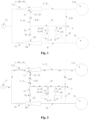
Figure 1 is a schematic diagram of the structure of an automatic dispensing device according to an embodiment of the present invention; -
Figures 2 to 5 are schematic diagrams of the structure of adding additives in different liquid storage boxes to different drums in an embodiment of the present invention. - Description of main components: 1. Suction structure; 2. Water supply pipeline; 3. Liquid storage box; 4. Connecting pipeline; 5. Water drum; 6. Flushing pipeline; 7. Control valve; 8. One-way valve; 9. Reversing valve; 10. Delivery waterway; 11. Negative pressure area; 12. Suction port; 13. Pump; 14. Liquid extraction pipeline; 15. Water inlet structure; 100. Venturi tube; 101. First Venturi tube; 21. First water supply pipeline; 31. First liquid storage box; 41. First connecting pipeline; 51. first water drum; 61. First flushing pipeline; 71. First control valve; 81. First one-way valve; 121. First suction port; 131. First pump; 141. First liquid extraction pipeline; 102, second venturi tube; 22, second water supply pipeline; 32, second liquid storage box; 42, second connecting pipeline; 52, second water drum; 62, second flushing pipeline; 72, second control valve; 82, second one-way valve; 122, second suction port; 132, second pump; 142, second liquid extraction pipeline.
- As shown in
Figures 1 to 5 , an embodiment of the present invention introduces a multi-drum washing machine, which includes a plurality of water drums 5 independently arranged, and each water drum 5 can process clothes respectively. The washing machine is provided with awater inlet structure 15 for introducing external water flow into the washing machine; the washing machine is also provided with an automatic dispensing device, which delivers additives along with the water flow flowing into the water inlet structure into the corresponding water drum 5, so as to use the additives delivered along with the water flow to process the clothes in the corresponding water drum 5. - In the embodiment of the present invention, the additives include but are not limited to the following types: detergents, softeners, disinfectants, fragrances, bleaches, etc.
- As shown in
Figures 1 to 5 , an automatic dispensing device is also introduced in an embodiment of the present invention. The automatic dispensing device can be applied to the above-mentioned multi-drum washing machine to dispense additives into the corresponding water drum 5 of the washing machine; it can also be applied to any existing equipment to dispense corresponding additives into any waterway in the equipment. - The automatic dispensing device described in the embodiment of the present invention includes a liquid storage box 3, which contains additives used for treating clothes; at least two water supply pipelines 2, the water inlet end of each water supply pipeline 2 is connected to the same water supply source, and the water supply source is the
water inlet structure 15 of the washing machine. Each water supply pipeline 2 has different and corresponding water outlets connected to each other, so that each water supply pipeline 2 can transport the incoming water to the water outlet of the corresponding pipeline. Adelivery waterway 10, the liquid storage box 3 is connected to thedelivery waterway 10 through a pump 13, and the additives in the corresponding liquid storage box 3 are extracted into thedelivery waterway 10 through the action of the pump 13. Thedelivery waterway 10 is connected in parallel with each water supply pipeline 2, and the additives extracted by the pump 13 in thedelivery waterway 10 are flushed to the water outlet of the selected water supply pipeline 2 by the water flow flowing through the selected water supply pipeline 2. - In the embodiment of the present invention, when the automatic dispensing device is installed on a multi-drum washing machine, the water outlets of each water supply pipeline 2 of the automatic dispensing device are connected to each water drum 5 of the washing machine in a one-to-one correspondence, and the water supply source is provided by the washing machine
water inlet structure 15, so that in the process of washing water entering the corresponding water drum 5 of the multi-drum washing machine, the additives are put into the corresponding water drum 5 together with the inlet water flow. Of course, for the needs of washing machine design, the number of water outlets of the automatic dispensing device and the number of water drums can also be set to be different, so that at least one water drum corresponds to multiple water outlets, or at least one water outlet corresponds to multiple water drums. - Through the above arrangement, the automatic dispensing device can extract additives from different liquid storage boxes into the delivery waterway through the pump, and use the water flow flowing through the corresponding water supply pipeline to dispense the extracted additives in the parallel delivery waterway to the corresponding water outlet along with the water flow, thereby achieving the purpose of dispensing additives in the same liquid storage box to multiple locations respectively through a set of system. At the same time, the above automatic dispensing device is installed on a multi-drum washing machine, so that multiple water drums of the multi-drum washing machine can share a set of additive dispensing system, thereby achieving the purpose of controllably dispensing additives into a selected water drum along with the incoming water flow.
- The automatic dispensing device described in the embodiment of the present invention includes at least two liquid storage boxes 3, each of which can store additives of different categories and/or different concentrations. Of course, the same additives can also be stored in some of the liquid storage boxes 3, so that one or more of the liquid storage boxes 3 can be used as a backup. Each liquid storage box 3 is connected to the
delivery waterway 10 through different liquid extraction pipelines 14; each liquid extraction pipeline 14 is provided with a pump 13, which is used to extract the additives in different liquid storage boxes 3 into thedelivery waterway 10, thereby realizing that different drums of the washing machine share a set of liquid storage boxes 3, so that various additives in a set of liquid storage boxes 3 can be controlled to be dispensed into different water drums 5. - As shown in
Figure 1 , this embodiment introduces an automatic dispensing device, including a liquid storage box 3, which contains additives used for treating clothes; at least two water supply pipelines 2, the water inlet of each water supply pipeline 2 is respectively connected to thewater inlet structure 15 of the multi-drum washing machine, and the water outlet of each water supply pipeline 2 is respectively connected to different, one-to-one corresponding water drums 5, so that each water supply pipeline 2 can transport the washing machine water to the corresponding water drum 5, so as to achieve the purpose of supplying washing water to any water drum 5 of the multi-drum washing machine. Each water supply pipeline 2 is provided with a suction structure 1, which can generate negative pressure through the water flow flowing through the corresponding water supply pipeline 2; the suction port 12 of the suction structure 1 is connected to the water outlet of thedelivery waterway 10 through the connecting pipeline 4, so that the additives extracted from thedelivery waterway 10 can be sucked into the suction structure 1, and the additives are dispensed into the corresponding washing machine water drum 5 along with the water flow. In the embodiment of the present invention, when the automatic dispensing device is installed on a multi-drum washing machine, the water outlets of the automatic dispensing device are connected to the water drums 5 of the washing machine in a one-to-one correspondence, and the water supply source is provided by thewater inlet structure 15 of the washing machine, so that in the process of washing water entering the corresponding water drum 5 of the multi-drum washing machine, the additives are dispensed into the corresponding water drum 5 together with the inlet water flow, so as to achieve the purpose of automatically dispensing the additives into the corresponding water drum 5 along with the inlet water flow. - In this embodiment, the suction structure 1 includes a venturi tube 100 provided in the water supply pipeline 2, which can generate negative pressure by the flow of water. The
negative pressure area 11 of the venturi tube 100 is provided with a suction port 12 connected to thedelivery waterway 10 and uses negative pressure to extract additives into the water supply pipeline 2. In this embodiment, both ends of the venturi tube 100 are connected to the water supply pipeline 2 and are respectively connected to the water inlet and the water outlet; the middle part of the venturi tube 100 is provided with a closing part in which the diameter of the pipe in the pipeline is convexly reduced. Due to the sudden decrease in the inner diameter of the pipe wall of the closing part, the water flow velocity in this area suddenly increases, so that the closing part forms anegative pressure area 11 that generates negative pressure as the water flows, and thenegative pressure area 11 is provided with a port connected to the outside, and the port constitutes the suction port 12 of the suction structure 1 connected to thedelivery waterway 10 through the connecting pipeline 4. Through the above arrangement, the suction structure 1 can be directly composed of a venturi tube 100 that generates a negative pressure suction effect according to changes in the water flow rate, thereby achieving the purpose of pumping the stored additives in thedelivery waterway 10 into the inlet water flow of the corresponding water supply pipeline 2 along with the inlet water flow, thereby achieving the purpose of putting the additives into the water drum of the washing machine. - In this embodiment, the water outlets of each water supply pipeline 2 are respectively connected to a corresponding, different water drum 5. Preferably, a one-way valve 8 (not indicated in the attached figure) is provided on the water supply pipeline 2 to ensure that the water in the pipeline flows in a single direction from the water inlet source end to the water outlet end. Thereby, the automatic dispensing device is fed with water through different water supply waterways to achieve the purpose of feeding water and delivering additives into different water drums respectively. Further preferably, as shown in
Figure 1 , a control valve 7 is provided at the water inlet end of the water supply pipeline 2 to control the on-off of the water flow of the water supply pipeline 2. The control valve 7 is provided at the upstream part of the suction structure 1 to achieve on-off control of the water inlet at the suction structure 1. - In this embodiment, the automatic dispensing device further includes a flushing pipeline 6, the water inlet end of the flushing pipeline 6 is connected to partially of the water supply pipeline 2 at the downstream of the venturi tube 100, and the water outlet end of the flushing pipeline 6 is connected to the water inlet of the
delivery waterway 10; the other end of thedelivery waterway 10 is a water outlet, which is connected to the suction port 12 of the suction structure 1 through the connecting pipeline 4. Through the above arrangement, the water flow at the water outlet end of the water supply pipeline 2 is directly introduced into thedelivery waterway 10, and then circulated back to the water supply pipeline 2 through the suction structure 1, and thedelivery waterway 10 is flushed with circulating water, so that the additives pumped into thedelivery waterway 10 by the pump 13 are all flushed into the water supply pipeline 2, and the additives remaining in the pipeline can be flushed, so as to ensure that the additives pumped into thedelivery waterway 10 by the pump 13 of the automatic dispensing device can be completely discharged into the water supply pipeline 2 with the water flow. At the same time, the purpose of flushing the automatic dispensing device and preventing the residual additives from affecting the subsequent use of the device can also be achieved. - Preferably, a one-way valve 8 can be provided on the flushing pipeline 6 and/or the connecting pipeline 4 to ensure that the water in the pipeline flows in a single direction from the water inlet end to the water outlet end. In the present embodiment, as shown in
Figure 1 , in order to avoid the water supply pipeline from diverting to the delivery waterway, a one-way valve 8 is provided on the connecting pipeline 4. The one-way valve 8 is used to ensure that the liquid in the connecting pipeline 4 flows only in a single direction from thedelivery waterway 10 to the water supply pipeline 2 to avoid backflow. - Preferably, a control valve 7 for controlling the water flow in the flushing pipeline 6 and/or the connecting pipeline 4 is provided to control the flow of flushing water from the water supply pipeline 2 to the delivery waterway 10 (not indicated in the drawings). In this embodiment, in order to ensure that each water supply pipeline 2 can be connected to the
delivery waterway 10 connected to the same set of additive storage boxes 3, and to achieve the effect of flushing and delivering the pumped additive, the following settings are made:
As shown inFigure 1 , each water supply pipeline 2 is connected to a flushing pipeline 6, and the water outlet end of each flushing pipeline 6 is connected to the same reversingvalve 9. The reversingvalve 9 is also connected to the water inlet of thedelivery waterway 10, so that under the control of the reversingvalve 9, each flushing pipeline 6 can be selectively connected to the water inlet of thedelivery waterway 10. - In this embodiment, the automatic dispensing device comprises at least two liquid storage boxes 3, and different types of additives are added to each liquid storage box 3, so that the automatic dispensing device can classify and automatically dispense different types of additives.
- The following is an example of a multi-drum washing machine with two water drums 5, namely the first water drum 51 and the
second water drum 52; and two liquid storage boxes 3, namely the first liquid storage box 31 and the secondliquid storage box 32. The specific structure is as follows:
As shown inFigure 1 to Figure 5 , in this embodiment, the water inlet end of the first water supply pipeline 21 is provided with a first venturi tube 101, and the water outlet end is connected to the first water drum 51. The water inlet end of the secondwater supply pipeline 22 is provided with asecond venturi tube 102, and the water outlet end is connected to thesecond water drum 52. The water outlet ends of the first water supply pipeline 21 and the secondwater supply pipeline 22 are respectively provided with ports, and the two ports are respectively connected to the water inlet end of a flushing pipeline 6. The water outlet ends of the two flushing pipelines 6 are connected to the same reversingvalve 9, and the reversingvalve 9 has two inlets and one outlet, and the two inlets are respectively connected to the water outlet ends of the first flushing pipeline 61 and thesecond flushing pipeline 62, and the outlet is connected to the water inlet of thedelivery waterway 10. The reversingvalve 9 has two states, which communicate one of the two inlets with the outlet, so as to realize that the first flushing pipeline 61 and thesecond flushing pipeline 62 are respectively communicated with thedelivery waterway 10. - In this embodiment, the water outlet of the
delivery waterway 10 is connected to the first suction port 121 of the first venturi tube 101 through the first connecting pipeline 41 provided with the first one-way valve 81, and is connected to thesecond suction port 122 of thesecond venturi tube 102 through the second connectingpipeline 42 provided with the second one-way valve 82. In this embodiment, in order to prevent the water flow in the water supply pipeline 2 from flowing back from the suction port 12 to thedelivery waterway 10, one-way valves 8 are respectively installed on the two connecting pipelines 4, so that the one-way valves 8 are used to control the flow direction of the liquid in the pipeline, so as to ensure that the liquid in the pipeline always flows in a single direction toward the side of the venturi tube 100, thereby preventing the water flow in the water supply pipeline 2 from directly flowing from the connecting pipeline 4 into thedelivery waterway 10. - In this embodiment, the first liquid storage box 31 is connected to the
delivery waterway 10 via a first liquid extraction pipeline 141 provided with a first pump 131, and the secondliquid storage box 32 is connected to thedelivery waterway 10 via a secondliquid extraction pipeline 142 provided with asecond pump 132. Preferably, in order to avoid the problem that the liquid in thedelivery waterway 10 flows back into the liquid storage box 3, a one-way valve 8 can be installed on the liquid extraction pipeline 14 provided with the pump 13, and the pump 13 can be directly integrated with a one-way valve assembly, or a one-way valve assembly can be integrated and installed at the liquid outlet of the liquid storage box 3, etc., so as to prevent the liquid from flowing back into the liquid storage box. - When the additive A in the first liquid storage box 31 is added into the first water drum 51, the automatic dispensing device is in the following state:
As shown inFigure 2 , the outlet of the reversingvalve 9 is connected to the first inlet and disconnected from the second inlet, the first pump 131 is working, thesecond pump 132 is not working, the first control valve 71 is opened, and thesecond control valve 72 is closed. At this time, thedelivery waterway 10 connects the first connecting pipeline 41 and the first flushing pipeline 61, and the additive A in the first liquid storage box 31 is acted upon by the first pump 131 and pumped into thedelivery waterway 10 through the first liquid extraction pipeline 141. The water flow in the first water supply pipeline 21 flows through the first venturi tube 101, and the first venturi tube 101 draws the additive A pumped in thedelivery waterway 10 into the first water supply pipeline 21, and flows into the first water drum 51 along with the water flow in the first water supply pipeline 21. At the same time, part of the incoming water flow in the first water supply pipeline 21 enters thedelivery waterway 10 to flush thedelivery waterway 10. The flushing water then flows back into the first water supply pipeline 21 through the first venturi tube 101 and flows into the first water drum 51 from the water outlet together with the incoming water flow. - When the additive B in the second
liquid storage box 32 is added into the first water drum 51, the automatic dispensing device is in the following operating state:
As shown inFigure 3 , the outlet of the reversingvalve 9 is connected to the first inlet and disconnected from the second inlet, the first pump 131 is not working, thesecond pump 132 is working, the first control valve 71 is opened, and thesecond control valve 72 is closed. At this time, thedelivery waterway 10 connects the first connecting pipeline 41 and the first flushing pipeline 61, and the additive B in the secondliquid storage box 32 is acted upon by thesecond pump 132 and pumped into thedelivery waterway 10 through the secondliquid extraction pipeline 142. The water flow in the first water supply pipeline 21 flows through the first venturi tube 101, and the first venturi tube 101 draws the additive B pumped in thedelivery waterway 10 into the first water supply pipeline 21, and flows into the first water drum 51 along with the water flow in the first water supply pipeline 21. At the same time, part of the incoming water flow in the first water supply pipeline 21 enters thedelivery waterway 10 to flush thedelivery waterway 10. The flushing water then flows back into the first water supply pipeline 21 through the first venturi tube 101 and flows into the first water drum 51 from the water outlet together with the incoming water flow. - When the additive A in the first liquid storage box 31 is added into the
second water drum 52, the automatic dispensing device is in the following operating state:
As shown inFigure 4 , the outlet of the reversingvalve 9 is disconnected from the first inlet and connected to the second inlet, the first pump 131 is working and thesecond pump 132 is not working, the first control valve 71 is closed and thesecond control valve 72 is opened. At this time, thedelivery waterway 10 connects the second connectingpipeline 42 and thesecond flushing pipeline 62, and the additive A in the first liquid storage box 31 is pumped into thedelivery waterway 10 by the first pump 131. The water flow in the secondwater supply pipeline 22 flows through thesecond venturi tube 102. Thesecond venturi tube 102 draws the additive A pumped in thedelivery waterway 10 into the secondwater supply pipeline 22, and flows into thesecond water drum 52 along with the water flow in the secondwater supply pipeline 22. At the same time, part of the incoming water flow in the secondwater supply pipeline 22 enters thedelivery waterway 10 to flush thedelivery waterway 10. The flushing water then flows back into the secondwater supply pipeline 22 through thesecond venturi tube 102 and flows into thesecond water drum 52 from the water outlet together with the incoming water flow. - When the additive B in the second
liquid storage box 32 is added into thesecond water drum 52, the automatic dispensing device is in the following operating state:
As shown inFigure 5 , the outlet of the reversingvalve 9 is disconnected from the first inlet and connected to the second inlet, the first pump 131 is not working, thesecond pump 132 is working, the first control valve 71 is closed, and thesecond control valve 72 is opened. At this time, thedelivery waterway 10 connects the second connectingpipeline 42 and thesecond flushing pipeline 62, and the additive B in the secondliquid storage box 32 is pumped into thedelivery waterway 10 by thesecond pump 132. The water flow in the secondwater supply pipeline 22 flows through thesecond venturi tube 102. Thesecond venturi tube 102 draws the additive B pumped in thedelivery waterway 10 into the secondwater supply pipeline 22, and flows into thesecond water drum 52 along with the water flow in the secondwater supply pipeline 22. At the same time, part of the incoming water flow in the secondwater supply pipeline 22 enters thedelivery waterway 10 to flush thedelivery waterway 10. The flushing water then flows back into the secondwater supply pipeline 22 through thesecond venturi tube 102 and flows into thesecond water drum 52 from the water outlet together with the incoming water flow. - In this embodiment, in order to increase the amount of additives dispensed by the automatic dispensing device at a single time, a labyrinth flow path can also be set on the
delivery waterway 10. The labyrinth flow path is composed of a waterway that is coiled and spirally arranged to extend the axial length of the pipeline. The labyrinth flow path is located at one end of thedelivery waterway 10 connected to the connecting pipeline 4, and the labyrinth flow path is located at the downstream of the place where each liquid storage box 3 is connected to thedelivery waterway 10 through the pump 13, so that the water inlet end of the labyrinth flow path is connected to the liquid storage boxes 3 at upstream, and the water outlet end is respectively connected to the inlet of each connecting pipeline 4 (not indicated in the drawings). - In this embodiment, in order to realize the metering detection of the dosage of the additive, the following settings can be made: a metering device for detecting the flow rate of the liquid flowing through is provided on the connecting pipe 4 between the labyrinth flow path and the suction port 12 of the suction structure. Of course, in the embodiment of the present invention, in order to simplify the structure, the metering component can also be directly integrated on the pump 13, so that the pump 13 itself is a metering pump, and the parameters of the pump 13 are used to directly measure and count the dosage of the additive. The pump 13 can be any existing metering pump with a metering function, for example: a metering pump that indirectly obtains the dosage by counting any parameter such as the number of revolutions of the impeller in the pump, the speed, time, power, etc.
- This embodiment also introduces a control method applied to the above-mentioned automatic dispensing device. When delivering additives, the pump 13 corresponding to the selected liquid storage box 3 is turned on, so that the additive in the selected liquid storage box 3 is pumped into the
delivery waterway 10. Water at the water supply source flows through a selected water supply pipeline 2 to the corresponding water outlet, and part of the water flow in the water supply pipeline 2 flows into thedelivery waterway 10, flushing the additive in thedelivery waterway 10 into the selected water supply pipeline 2, and then flushing it to the outlet of the selected water supply pipeline 2 with the water flow in the water supply pipeline 2. - In this embodiment, the steps of pumping the additive in the liquid storage box 3 into the
delivery waterway 10 via the pump 13 and introducing water into the water supply pipe 2 to flush the additive in thedelivery waterway 10 into the water drum 5 can be performed simultaneously. Or the steps of pumping the additive in the liquid storage box 3 into thedelivery waterway 10 via the pump 13 and introducing water into the water supply pipe 2 to flush the additive in thedelivery waterway 10 into the water drum 5 can be performed alternately. - Therefore, the control method of the present invention has more diverse delivery methods and can realize different delivery logics compared to the limited technology. In particular, through the above-mentioned setting, when the additive is delivered, the steps of pumping the additive in the liquid storage box into the delivery waterway through the pump and flushing the additive in the delivery waterway into the water drum can be executed simultaneously, making the delivery process more concise and time-saving.
- In this embodiment, when the water at the water supply source flows through a selected water supply pipeline 2 to the corresponding water outlet, the negative pressure generated when the water flows through the suction structure 1 provided on the water supply pipeline 2 is used to extract the additive in the
delivery waterway 10, and enter the corresponding water supply pipeline 2 through the suction port 12, and then rush to the outlet of the selected water supply pipeline 2 with the water flow in the water supply pipeline 2. Through the above arrangement, the additive is injected into the delivery waterway with power provided by the pump, and the additive is dispensed into the drum with power provided by the suction structure provided on the delivery waterway, thereby increasing the flow rate of the additive and further improving the dispensing reaction efficiency. - Preferably, in the present embodiment, when flushing the additive in the
delivery waterway 10, the flushing pipeline 6 connected to the water supply pipeline 2 is selected to be connected to thedelivery waterway 10, and the liquid storage box 3 is disconnected from thedelivery waterway 10. Water flows through the water supply pipeline 2, and at least part of the water flows through the flushing pipeline 6 to thedelivery waterway 10, so as to flush the additive in thedelivery waterway 10 that has been extracted by the liquid storage box 3 by the pump 13. The flushing water containing the additive then flows back into the water supply pipeline 2 to ensure that the circulating flushing water can be used to completely flush the additive in thedelivery waterway 10 during the additive delivery process, thereby achieving the effect of preventing the residual of the additive in the delivery waterway. - In this embodiment, when flushing the additives in the
delivery waterway 10, the water outlet end of thedelivery waterway 10 is connected to the suction port 12 of the suction structure 1 provided on the selected water supply pipeline 2, so that after thedelivery waterway 10 is flushed through the flushing pipeline 6, the flushing water that flows back from the suction port 12 to the selected water supply pipeline 2 can flow out through the water outlet of the selected water supply pipeline 2, thereby switching the water supply to the two water supply pipelines 2, and achieving the effect of respectively putting additives into different water drums 5, thereby improving the diversity of additive placement. - In this embodiment, during the normal water intake process of the washing machine: the
water inlet structure 15 of the washing machine intakes water into the corresponding water drum 5 through the selected water supply pipeline 2, part of the intake water flow will flow through thedelivery waterway 10, and part of the water flow will flush thedelivery waterway 10, so that the water supply pipeline 2 intakes water into the water drum 5 and the flushing of thedelivery waterway 10 can be performed simultaneously. - In this embodiment, the automatic dispensing device can dispense different types of additives stored in each liquid storage box 3 respectively. When the automatic dispensing device dispenses additives, one of the suction ports 12 is connected to the
delivery waterway 10, and one of the pumps 13 corresponding to each liquid storage box 3 is turned on, so that the corresponding liquid storage box 3 is connected to thewater supply pipeline 10, and the additive pump 13 stored in the corresponding liquid storage box 3 is dispensed to thedelivery waterway 10, and is flushed into the corresponding water supply pipeline 2 with the inlet water flow under the action of the suction structure 1, and enters the corresponding water drum 5 with the water flow in the water supply pipeline 2. - The following is an example of a multi-drum washing machine with two water drums 5, namely the first water drum 51 and the
second water drum 52; and two liquid storage boxes 3, namely the first liquid storage box 31 and the secondliquid storage box 32. The specific control method is as follows:
When the additive A stored in the first liquid storage box 31 is added into the first water drum 51. - As shown in
Figure 2 , the first water supply pipeline 21 of the automatic dispensing device intakes water into the first water drum 51. During the water intake process, the first pump 131 connected to the outlet of the first liquid storage box 31 is turned on, and the first pump 131 pumps the additive A stored in the first liquid storage box 31 to thedelivery waterway 10. When the water in the first water supply pipeline 21 flows through the first venturi tube 101, negative pressure is generated, and the additive A in thedelivery waterway 10 is sucked into the first water supply pipeline 21 by the negative pressure, and flushed into the first water drum 51 along with the incoming water flow. During the above process, part of the water in the first water supply pipeline 21 flows through the first flushing pipeline 61, thedelivery waterway 10, and the first connecting pipeline 41 into the first venturi tube 101, so as to flush the residual additive A in the suction structure 1 and thedelivery waterway 10, so that the additive A pumped to thedelivery waterway 10 by the first pump 131 is completely flushed into the first water drum 51 along with the flushing water flow. - When the additive A stored in the first liquid storage box 31 is added into the
second water drum 52. - As shown in
Figure 4 , the secondwater supply pipeline 22 of the automatic dispensing device flows into thesecond water drum 52. During the water intake process, the first pump 131 provided at the outlet of the first liquid storage box 31 is turned on, and the first pump 131 pumps the additive A stored in the first liquid storage box 31 to thedelivery waterway 10. Negative pressure is generated when the secondwater supply pipeline 22 flows through thesecond venturi tube 102, and the additive A in thedelivery waterway 10 is sucked into the secondwater supply pipeline 22 by the negative pressure, and flushed into thesecond water drum 52 along with the incoming water flow. During the above process, part of the water in the secondwater supply pipeline 22 flows through thesecond flushing pipeline 62, thedelivery waterway 10, and the second connectingpipeline 42 into thesecond venturi tube 102, so as to flush the residual additive A in the suction structure 1 and thedelivery waterway 10, so that the additive A pumped to thedelivery waterway 10 by the first pump 131 is completely flushed into thesecond water drum 52 along with the flushing water flow. - When the additive B stored in the second
liquid storage box 32 is added into the first water drum 51. - As shown in
Figure 3 , the first water supply pipeline 21 of the automatic dispensing device intakes water into the first water drum 51. During the water intake process, thesecond pump 132 provided at the outlet of the secondliquid storage box 32 is turned on, and thesecond pump 132 pumps the additive B stored in the secondliquid storage box 32 to thedelivery waterway 10. Negative pressure is generated when the water in the first water supply pipeline 21 flows through the first venturi tube 101, and the additive B in thedelivery waterway 10 is sucked into the first water supply pipeline 21 by the negative pressure, and flushed into the first water drum 51 along with the inflowing water flow. During the above process, part of the water in the first water supply pipeline 21 flows through the first flushing pipeline 61, thedelivery waterway 10, and the first connecting pipeline 41 into the first venturi tube 101, so as to flush the residual additive B in the suction structure 1 and thedelivery waterway 10, so that the additive B pumped into thedelivery waterway 10 by thesecond pump 132 is completely flushed into the first water drum 51 along with the flushing water flow. - When the additive B stored in the second
liquid storage box 32 is added into thesecond water drum 52. - As shown in
Figure 5 , the secondwater supply pipeline 22 of the automatic dispensing device intakes water into thesecond water drum 52. During the water intake process, thesecond pump 132 provided at the outlet of the secondliquid storage box 32 is turned on, and thesecond pump 132 pumps the additive B stored in the secondliquid storage box 32 to thedelivery waterway 10. When the secondwater supply pipeline 22 flows through thesecond venturi tube 102, negative pressure is generated, and the additive B in thedelivery waterway 10 is sucked into the secondwater supply pipeline 22 by the negative pressure, and flushed into thesecond water drum 52 along with the incoming water flow. During the above process, part of the water in the secondwater supply pipeline 22 flows through thesecond flushing pipeline 62, thedelivery waterway 10, and the second connectingpipeline 42 into thesecond venturi tube 102, so as to flush the residual additive B in the suction structure 1 and thedelivery waterway 10, so that the additive B pumped into thedelivery waterway 10 by thesecond pump 132 is completely flushed into thesecond water drum 52 along with the flushing water flow. - The above is only a preferred embodiment of the present invention, and does not limit the present invention in any form. Although the present invention has been disclosed as a preferred embodiment, it is not used to limit the present invention. Any technician familiar with this patent can make some changes or modify the technical contents suggested above into equivalent embodiments without departing from the scope of the technical solution of the present invention. However, any simple modification, equivalent change and modification made to the above embodiments according to the technical essence of the present invention without departing from the content of the technical solution of the present invention still fall within the scope of the solution of the present invention.
Claims (15)
- An automatic dispensing device, comprising:a liquid storage box (3), containing additive;a delivery waterway (10), wherein the liquid storage box (3) is connected to the delivery waterway (10) via a pump (13), and the additives in the liquid storage box (3) is extracted into the delivery waterway (10) by an action of the pump (13);at least two water supply pipelines (2), respectively transporting intake water to outlets of the corresponding water supply pipelines (2); whereinthe delivery waterway (10) is connected in parallel respectively to each of the water supply pipelines (2), and the additive extracted by the pump (13) in the delivery waterway (10) is flushed to the outlet of the selected water supply pipeline (2) by water flow flowing through the selected water supply pipeline (2).
- The automatic dispensing device according to claim 1, characterized in thateach of the water supply pipelines (2) is provided with a suction structure (1), which is capable of generating negative pressure through the water flow flowing through the corresponding water supply pipeline (2);a suction port (12) of the suction structure (1) is connected to an outlet of the delivery waterway (10), and the additive pumped into the delivery waterway (10) is sucked into the suction structure (1) and transported to the outlet of the corresponding water supply pipeline (2) along with the water flow.
- The automatic dispensing device according to claim 2, characterized in that
the suction port (12) of the suction structure (1) is connected to the outlet of the delivery waterway (10) via a corresponding connecting pipeline (4), and the connecting pipeline (4) is provided with a one-way valve (8) for controlling a fluid to flow only in a direction of the delivery waterway (10) toward the suction structure (1). - The automatic dispensing device according to any one of claims 1 to 3, characterized in thateach of the water supply pipelines (2) is also connected to a flushing pipeline (6), and an inlet of the delivery waterway (10) is connected to the flushing pipeline (6), so that part of the water flow of the water supply pipeline (2) is directly introduced into the delivery waterway (10) to flush the additive in the delivery waterway (10), and then the flushing water flows back to the water supply pipeline (2) and flows out through the outlet;preferably, a one-way valve is provided on the flushing pipeline (6) to ensure that the water flows in a single direction along the water supply pipeline (2) toward the delivery waterway;preferably, a control valve for controlling on/off of the water flow in the flushing pipeline (6) is provided on the flushing pipeline (6).
- The automatic dispensing device according to claim 4, characterized in that a water outlet of each the flushing pipeline (6) is connected to the inlet of the delivery waterway (10) through the same reversing valve (9), and the reversing valve (9) is used to control each the flushing pipeline (6) to be connected to the delivery waterway (10) selectively.
- The automatic dispensing device according to claim 4, characterized in that the suction structure (1) provided on the water supply pipeline (2) is located at an upstream of where the water supply pipeline (2) connected with the flushing pipeline (6).
- The automatic dispensing device according to any one of claims 1 to 6, characterized in that outlets of liquid storage box (3) are connected to the same delivery waterway (10) via corresponding pumps (13), and when the pumps (13) are in working state, the additive stored in the corresponding liquid storage box (3) is pumped into the delivery waterway (10);preferably, the pump (13) is integrated with an on-off valve assembly; when the pump (13) is in a non-operating state, the outlet of the liquid storage box (3) is disconnected from the delivery waterway (10), and the additive stored in the liquid storage box (3) not flow into the delivery waterway (10);preferably, the pump (13) is integrated with a metering component for metering an amount of additive flowing through the pump (13) and pumped from the liquid storage box (3) to the delivery waterway (10);preferably, the pump (13) is integrated with a one-way valve assembly for limiting a fluid flowing through the pump (13) to flow in only one direction along the liquid storage box (3) to the delivery waterway (10).
- The automatic dispensing device according to any one of claims 1 to 7, characterized in that water outlet end of each the water supply pipeline (2) is respectively connected to the corresponding and different outlet;preferably, the water supply pipeline (2) is provided with a one-way valve for allowing the water to flow in a single direction from a water inlet end to the water outlet end;preferably, a control valve (7) is provided at the inlet end of the water supply pipeline (2) for controlling on-off of water flow into the pipeline.
- The automatic dispensing device according to any one of claims 2 to 8, characterized in that the suction structure (1) comprises a venturi tube (100) provided in the water supply pipeline (2) and capable of generating negative pressure by water flowing through, and a negative pressure area (11) is provided with a suction port (12) connected to the liquid storage box (3) and utilizing negative pressure to extract the additive into the water supply pipeline (2);
preferably, both ends of the venturi tube (100) are connected to the corresponding water supply pipeline (2) and are respectively connected to a water inlet end and a water outlet end; a middle part of the venturi tube (100) is provided with a constricted portion with a convexly reduced diameter, and negative pressure is generated at the constricted portion as a flow velocity of the water flow increases suddenly to form the negative pressure area (11); the negative pressure area (11) is provided with a port connected to outside, and the port constitutes the suction port (12) of the suction structure (1) connected to the delivery waterway (10). - The automatic dispensing device according to any one of claims 1 to 9, characterized in that a labyrinth flow path is arranged on the delivery waterway (10) and is in a spiral arrangement to extend an axial length of the pipeline; the labyrinth flow path is located at a downstream of a connection between the delivery waterway (10) and each the liquid storage box (3).
- A control method of the automatic dispensing device according to any one of claims 1 to 10, characterized in that when dispensing the additive, the pump (13) corresponding to the selected liquid storage box (3) is turned on, so that the additive in a selected liquid storage box (3) is pumped into the delivery waterway (10);
water from a water supply source flows through a selected water supply pipeline (2) to a corresponding outlet, and part of the water in the water supply pipeline (2) flows into the delivery waterway (10), flushing the additive in the delivery waterway (10) into the selected water supply pipeline (2), and then flushing the additive to the selected outlet of the water supply pipeline (2) along with the water flow in the water supply pipeline (2). - The control method of the automatic dispensing device according to claim 11, characterized in that when water at the water supply source flows through the selected water supply pipeline (2) to the corresponding outlet, a negative pressure generated when the water flows through the suction structure (1) provided on the water supply pipeline (2) is utilized to extract the additive in the delivery waterway (10), and the additive enters the selected water supply pipeline (2) through a suction port (12), and then is flushed to the outlet of the selected water supply pipeline (2) along with the water flow in the water supply pipeline (2).
- The control method of the automatic dispensing device according to claim 11 or 12, characterized in that when flushing the additive in the delivery waterway (10), the flushing pipeline (6) connected to the water supply pipeline (2) is selected to be connected to the delivery waterway (10), and the liquid storage box (3) is disconnected from the delivery waterway (10), and at least part of the water flowing through the water supply pipeline (2) flows through the flushing pipeline (6) to the delivery waterway (10), so as to flush the additive in the delivery waterway (10);
preferably, when flushing the additive in the delivery waterway (10), a water outlet end of the delivery waterway (10) is connected to the suction port (12) of the suction structure (1) provided on the selected water supply pipeline (2), and the flushing water after flushing the delivery waterway (10) through the flushing pipeline (6) is returned from the suction port (12) to the selected water supply pipeline (2) through the suction port (12) by means of the negative pressure generated by the suction structure (1), and flows out through the water outlet of the water supply pipeline (2) along with the water flow. - A multi-drum washing machine, comprising at least two water drums (5) and the automatic dispensing device according to any one of claims 1 to 10, characterized in that each of the water drums (5) is connected to each outlet of the automatic dispensing device in a one-to-one correspondence, so that the additive extracted from the liquid storage box (3) is controllably transported to any of the water drums (5).
- The multi-drum washing machine according to claim 14, characterized in that the water inlet ends of the water supply pipes (2) of the automatic dispensing device are respectively connected to a water inlet structure (15) of the washing machine, and the washing water supplied by the water inlet structure (15) of the washing machine serves as the water supply source for the water inlet ends of the water supply pipes (2); the washing water is configured to selectively flow into one of the water supply pipes (2), and flows from the outlet of the water supply pipe (2) to the corresponding water drum (5), so that the additive pumped into the corresponding water supply pipe (2) flows into the corresponding water drum (5) along with the washing machine inlet water flow.
Applications Claiming Priority (2)
| Application Number | Priority Date | Filing Date | Title |
|---|---|---|---|
| CN202211218069.2A CN117845555A (en) | 2022-09-30 | 2022-09-30 | Automatic dispensing device and control method and multi-drum washing machine |
| PCT/CN2023/115392 WO2024066859A1 (en) | 2022-09-30 | 2023-08-29 | Automatic dispensing device, control method, and multi-drum washing machine |
Publications (2)
| Publication Number | Publication Date |
|---|---|
| EP4582625A1 true EP4582625A1 (en) | 2025-07-09 |
| EP4582625A4 EP4582625A4 (en) | 2025-12-10 |
Family
ID=90476066
Family Applications (1)
| Application Number | Title | Priority Date | Filing Date |
|---|---|---|---|
| EP23870102.3A Pending EP4582625A4 (en) | 2022-09-30 | 2023-08-29 | Automatic dispensing device, control method, and multi-drum washing machine |
Country Status (6)
| Country | Link |
|---|---|
| US (1) | US20260110132A1 (en) |
| EP (1) | EP4582625A4 (en) |
| JP (1) | JP2025531508A (en) |
| CN (1) | CN117845555A (en) |
| AU (1) | AU2023350301A1 (en) |
| WO (1) | WO2024066859A1 (en) |
Family Cites Families (13)
| Publication number | Priority date | Publication date | Assignee | Title |
|---|---|---|---|---|
| JP2001129292A (en) * | 1999-11-04 | 2001-05-15 | Sharp Corp | Cleaning equipment |
| CN201258409Y (en) * | 2008-08-15 | 2009-06-17 | 无锡小天鹅股份有限公司 | Washing machine detergent feeding device utilizing Venturi effect |
| CN104178975B (en) * | 2013-05-22 | 2018-02-16 | 青岛海尔洗衣机有限公司 | The automatic washing machine and its method for launching additive |
| DE102015116919A1 (en) * | 2015-10-06 | 2017-04-06 | Miele & Cie. Kg | Washing machine with a device for the supply of liquid and dosing device for liquid |
| CN107881710B (en) * | 2016-09-30 | 2023-11-03 | 杭州神林电子有限公司 | Flow path switcher and liquid detergent dispensing device |
| CN110629464B (en) * | 2018-06-21 | 2022-04-26 | 青岛海尔洗涤电器有限公司 | Automatic feeding device, control method and multi-drum washing machine |
| WO2019242546A1 (en) * | 2018-06-21 | 2019-12-26 | 青岛海尔滚筒洗衣机有限公司 | Automatic dispensing device and control method thereof, and multi-drum washing machine |
| CN208455295U (en) * | 2018-06-29 | 2019-02-01 | 杭州神林电子有限公司 | Detergent dispenser |
| DE102019135125A1 (en) * | 2019-12-19 | 2021-06-24 | Miele & Cie. Kg | Device for supplying treatment agent for a washing machine and washing machine |
| CN212199706U (en) * | 2019-12-30 | 2020-12-22 | 杭州神林电子有限公司 | A double barrel dispenser |
| JP2022015157A (en) * | 2020-07-08 | 2022-01-21 | 東芝ライフスタイル株式会社 | Clothing treatment apparatus |
| US12485434B2 (en) * | 2020-08-31 | 2025-12-02 | Chongqing Haier Drum Washing Machine Co., Ltd. | Nozzle structure, additive delivery device and washing machine |
| CN218910874U (en) * | 2022-09-30 | 2023-04-25 | 青岛海尔洗衣机有限公司 | Automatic throwing device and multi-drum washing machine |
-
2022
- 2022-09-30 CN CN202211218069.2A patent/CN117845555A/en active Pending
-
2023
- 2023-08-29 WO PCT/CN2023/115392 patent/WO2024066859A1/en not_active Ceased
- 2023-08-29 EP EP23870102.3A patent/EP4582625A4/en active Pending
- 2023-08-29 JP JP2025518425A patent/JP2025531508A/en active Pending
- 2023-08-29 US US19/117,029 patent/US20260110132A1/en active Pending
- 2023-08-29 AU AU2023350301A patent/AU2023350301A1/en active Pending
Also Published As
| Publication number | Publication date |
|---|---|
| US20260110132A1 (en) | 2026-04-23 |
| WO2024066859A1 (en) | 2024-04-04 |
| AU2023350301A1 (en) | 2025-05-01 |
| JP2025531508A (en) | 2025-09-19 |
| CN117845555A (en) | 2024-04-09 |
| EP4582625A4 (en) | 2025-12-10 |
Similar Documents
| Publication | Publication Date | Title |
|---|---|---|
| CN109518425B (en) | Detergent delivery system | |
| US11987922B2 (en) | Automatic feeding device, control method thereof and multi drum washing machine | |
| CN210287842U (en) | A water inlet device that automatically dispenses detergent | |
| CN110629464A (en) | Automatic feeding device and control method, and multi-drum washing machine | |
| CN110629465A (en) | Automatic feeding device and control method, and multi-drum washing machine | |
| CN106758016B (en) | Washing liquid feeding system, washing equipment and washing liquid feeding method | |
| CN110629463A (en) | Automatic feeding device and control method, and multi-drum washing machine | |
| CN107059350A (en) | A kind of disposable detergent delivers structure, washing machine and put-on method | |
| EP3521500B1 (en) | Flow patch switcher and liquid detergent dispensing apparatus | |
| CN218910874U (en) | Automatic throwing device and multi-drum washing machine | |
| US20260110132A1 (en) | Automatic dispensing device, control method and multi-drum washing machine | |
| CN211772147U (en) | Additive injection device and washing machine | |
| WO2023185316A1 (en) | Automatic additive dispensing device and washing machine control method | |
| CN211571119U (en) | Additive injection device and washing machine | |
| CN219218456U (en) | An automatic feeding device and a multi-drum washing machine | |
| CN112376222A (en) | A put in subassembly, put in device and washing machine for putting in lotion | |
| CN112239938A (en) | Additive feeding device and washing machine | |
| CN112239936B (en) | Additive feeding device and washing machine | |
| CN118056941A (en) | Automatic dispensing device, multi-drum washing machine and control method | |
| CN216378806U (en) | Anti-siphon detergent dispensing system | |
| CN118422470A (en) | External delivery module and clothing processing equipment | |
| CN112239937B (en) | Additive dispensing device and washing machine | |
| CN117286683A (en) | Detergent quantitative dosing device, laundry processing equipment, quantitative dosing method | |
| CN112900015A (en) | Detergent dispensing system | |
| CN223738343U (en) | Multi-drum washing machine |
Legal Events
| Date | Code | Title | Description |
|---|---|---|---|
| STAA | Information on the status of an ep patent application or granted ep patent |
Free format text: STATUS: THE INTERNATIONAL PUBLICATION HAS BEEN MADE |
|
| PUAI | Public reference made under article 153(3) epc to a published international application that has entered the european phase |
Free format text: ORIGINAL CODE: 0009012 |
|
| STAA | Information on the status of an ep patent application or granted ep patent |
Free format text: STATUS: REQUEST FOR EXAMINATION WAS MADE |
|
| 17P | Request for examination filed |
Effective date: 20250401 |
|
| AK | Designated contracting states |
Kind code of ref document: A1 Designated state(s): AL AT BE BG CH CY CZ DE DK EE ES FI FR GB GR HR HU IE IS IT LI LT LU LV MC ME MK MT NL NO PL PT RO RS SE SI SK SM TR |
|
| A4 | Supplementary search report drawn up and despatched |
Effective date: 20251107 |
|
| RIC1 | Information provided on ipc code assigned before grant |
Ipc: D06F 39/02 20060101AFI20251103BHEP Ipc: D06F 39/08 20060101ALI20251103BHEP Ipc: D06F 29/00 20060101ALI20251103BHEP Ipc: D06F 33/30 20200101ALN20251103BHEP Ipc: D06F 105/02 20200101ALN20251103BHEP Ipc: D06F 105/06 20200101ALN20251103BHEP Ipc: D06F 105/42 20200101ALN20251103BHEP |
|
| DAV | Request for validation of the european patent (deleted) | ||
| DAX | Request for extension of the european patent (deleted) |