EP4582370A1 - Self-cleaning multi-servings beverage dispensing system - Google Patents
Self-cleaning multi-servings beverage dispensing system Download PDFInfo
- Publication number
- EP4582370A1 EP4582370A1 EP24223111.6A EP24223111A EP4582370A1 EP 4582370 A1 EP4582370 A1 EP 4582370A1 EP 24223111 A EP24223111 A EP 24223111A EP 4582370 A1 EP4582370 A1 EP 4582370A1
- Authority
- EP
- European Patent Office
- Prior art keywords
- cleaning
- water
- pump
- ingredient
- self
- Prior art date
- Legal status (The legal status is an assumption and is not a legal conclusion. Google has not performed a legal analysis and makes no representation as to the accuracy of the status listed.)
- Granted
Links
Images





Classifications
-
- B—PERFORMING OPERATIONS; TRANSPORTING
- B67—OPENING, CLOSING OR CLEANING BOTTLES, JARS OR SIMILAR CONTAINERS; LIQUID HANDLING
- B67D—DISPENSING, DELIVERING OR TRANSFERRING LIQUIDS, NOT OTHERWISE PROVIDED FOR
- B67D1/00—Apparatus or devices for dispensing beverages on draught
- B67D1/07—Cleaning beverage-dispensing apparatus
-
- A—HUMAN NECESSITIES
- A47—FURNITURE; DOMESTIC ARTICLES OR APPLIANCES; COFFEE MILLS; SPICE MILLS; SUCTION CLEANERS IN GENERAL
- A47J—KITCHEN EQUIPMENT; COFFEE MILLS; SPICE MILLS; APPARATUS FOR MAKING BEVERAGES
- A47J31/00—Apparatus for making beverages
- A47J31/44—Parts or details or accessories of beverage-making apparatus
- A47J31/60—Cleaning devices
-
- B—PERFORMING OPERATIONS; TRANSPORTING
- B67—OPENING, CLOSING OR CLEANING BOTTLES, JARS OR SIMILAR CONTAINERS; LIQUID HANDLING
- B67D—DISPENSING, DELIVERING OR TRANSFERRING LIQUIDS, NOT OTHERWISE PROVIDED FOR
- B67D1/00—Apparatus or devices for dispensing beverages on draught
- B67D1/08—Details
- B67D1/0878—Safety, warning or controlling devices
- B67D1/0882—Devices for controlling the dispensing conditions
-
- B—PERFORMING OPERATIONS; TRANSPORTING
- B67—OPENING, CLOSING OR CLEANING BOTTLES, JARS OR SIMILAR CONTAINERS; LIQUID HANDLING
- B67D—DISPENSING, DELIVERING OR TRANSFERRING LIQUIDS, NOT OTHERWISE PROVIDED FOR
- B67D1/00—Apparatus or devices for dispensing beverages on draught
- B67D1/08—Details
- B67D1/0888—Means comprising electronic circuitry (e.g. control panels, switching or controlling means)
-
- B—PERFORMING OPERATIONS; TRANSPORTING
- B67—OPENING, CLOSING OR CLEANING BOTTLES, JARS OR SIMILAR CONTAINERS; LIQUID HANDLING
- B67D—DISPENSING, DELIVERING OR TRANSFERRING LIQUIDS, NOT OTHERWISE PROVIDED FOR
- B67D1/00—Apparatus or devices for dispensing beverages on draught
- B67D1/08—Details
- B67D1/10—Pump mechanism
- B67D1/108—Pump mechanism of the peristaltic type
-
- B—PERFORMING OPERATIONS; TRANSPORTING
- B67—OPENING, CLOSING OR CLEANING BOTTLES, JARS OR SIMILAR CONTAINERS; LIQUID HANDLING
- B67D—DISPENSING, DELIVERING OR TRANSFERRING LIQUIDS, NOT OTHERWISE PROVIDED FOR
- B67D2210/00—Indexing scheme relating to aspects and details of apparatus or devices for dispensing beverages on draught or for controlling flow of liquids under gravity from storage containers for dispensing purposes
- B67D2210/00002—Purifying means
- B67D2210/00013—Sterilising means
- B67D2210/00015—UV radiation
Definitions
- the present disclosure relates to the field of beverage dispensing systems. More specifically, the present disclosure presents a self-cleaning multi-servings beverage dispensing system.
- the present disclosure provides a self-cleaning multi-servings beverage dispensing system adapted for preparing and serving a beverage.
- the system comprising a container engaging inlet port adapted for removably engaging a container storing an ingredient liquid.
- the system comprises a liquid extraction component slidably movable between a retracted position and an extended position. The liquid extraction component is not in contact with the ingredient liquid when the container is engaged in the container engaging inlet port and the liquid extraction component is in the retracted position. The liquid extraction component is in contact with the ingredient liquid when the container is engaged in the container engaging inlet port and the liquid extraction component is in the extended position.
- the system comprises an actuator adapted for moving the liquid extraction component between the retracted position and the extended position.
- the system comprises an ingredient pump for extracting at least some of the ingredient liquid from the container via the liquid extraction component when the liquid extraction component is in the extended position and the container is engaged in the container engaging inlet port, and transferring the extracted ingredient liquid from the liquid extraction component to a mixing unit.
- the system comprises a water tank for storing water and a water pump for transferring water from the water tank to the mixing unit.
- the system comprises the mixing unit for receiving and mixing the ingredient liquid transferred to the mixing unit and the water transferred to the mixing unit.
- the system comprises a mixing unit outlet for pouring a content of the mixing unit.
- the system comprises a cleaning pump for transferring cleaning water from the water tank to the liquid extraction component.
- the system comprises a controller comprising electronic means for controlling operations of the beverage dispensing system.
- the controller is adapted to perform a self-cleaning procedure by sending commands to the cleaning pump, the water pump and the ingredient pump to execute at least one of the following functionalities.
- An air cleaning functionality comprising a transfer of air by the ingredient pump through the liquid extraction component to the mixing unit, the air being sucked into the liquid extraction component via the liquid extraction inlet.
- a water cleaning functionality comprising a transfer of water by the water pump from the water tank to the mixing unit, a transfer of cleaning water by the cleaning pump from the water tank to the liquid extraction component, and a transfer of the cleaning water by the ingredient pump from the liquid extraction component to the mixing unit.
- the design of the liquid extraction component 120 is not limited to the implementation described in the present disclosure and illustrated in Figure 3 . Any design of the liquid extraction component 120 allowing to perform the beverage dispensing and the self-cleaning procedures described in the following paragraphs is within the scope of the present disclosure.
- Action 2 the controller 180 commands the water pump 160 to transfer water from the water tank 230 to the mixing unit 140 through the water filter 210.
- the water filter 210 is not present and the water is transferred directly from the water tank 230 to the mixing unit 140 (the water pump 160 connects directly the water tank 230 to the mixing unit 140).
- Action 3 the controller 180 commands the ingredient pump 170 to extract (by exerting a suction) ingredient liquid from the ingredient container 110 via the liquid extraction component 120 and to transfer the extracted ingredient liquid from the liquid extraction component 120 to the mixing unit 140. Under the action of the ingredient pump 170, the beverage resulting from mixing the ingredient liquid with the water in the mixing unit 140, is further transferred to, and dispensed by, the faucet 150.
- the order of actions 1, 2 and 3 may vary based on the implementation of the beverage dispensing procedure.
- the cleaning pump 220 is not active (no water is transferred to the liquid extraction component 120.
- the controller 180 commands the actuator 130 to move the liquid extraction component 120 downwardly to disengage from the ingredient container 110, in the retracted position of the liquid extraction component 120. In its retracted position, the liquid extraction component 120 is no longer in contact with the ingredient liquid stored in the ingredient container 110.
- the controller 180 also commands the water pump 160 and the ingredient pump 170 to stop (e.g. for a short period of time before starting the self-cleaning procedure).
- the self-cleaning procedure is performed.
- the self-cleaning procedure is based on the following two functionalities: water cleaning functionality (illustrated in Figure 9 ) and air cleaning functionality (illustrated in Figure 10 ).
- water cleaning functionality illustrated in Figure 9
- air cleaning functionality illustrated in Figure 10 .
- Action 1 the controller 180 commands the water pump 160 to transfer water from the water tank 230 to the mixing unit 140 (through the water filter 210 when present as illustrated in Figure 9 ).
- Action 2 the controller 180 commands the cleaning pump 220 to transfer cleaning water from the water tank 230 to the liquid extraction component 120 (through the water filter 210 when present).
- Action 3 the controller 180 commands the ingredient pump 170 to transfer the cleaning water from the liquid extraction component 120 to the mixing unit 140. Under the action of the ingredient pump 170, the cleaning water resulting from mixing the cleaning water transferred by the ingredient pump 170 from the liquid extraction component 120 and the water transferred by the water pump 160 from the water tank 230 (though the water filter 210 if present), is further transferred to, and dispensed by, the faucet 150.
- the order of actions 1, 2 and 3 may vary based on the implementation of the water cleaning functionality. However, in the configuration illustrated in Figure 9 , the water pump 160 and the cleaning pump 220 need to be activated simultaneously to circulate cleaning water through the liquid extraction component 120. In an alternative configuration (not represented in the Figures), the cleaning pump 220 can be directly connected to the water tank 230, in which case it can be operated independently of the water pump 160.
- the speed of the corresponding pump is set to a given value (which determines a corresponding flow rate of fluid through the pump).
- the given speed value of each pump (160, 220 and 170) is transmitted via the respective commands sent by the controller 180.
- the speed of each pump (160, 220 and 170) remains constant during the execution of the water cleaning functionality.
- the speed of at least one of the pumps (160, 220 or 170) varies during the execution of the water cleaning functionality.
- the pumps (160, 220 and 170) are active for the same duration corresponding to the duration of the execution of the water cleaning functionality. Alternatively, at least one of the pumps (160, 220 or 170) is not active during the entire duration of the execution of the water cleaning functionality. For example, one of the pumps becomes active a certain time after the beginning of the execution of the water cleaning functionality, becomes inactive a certain time before the end of the execution of the water cleaning functionality, etc.
- the controller 180 commands the pump to stop. At least, at the end of the execution of the water cleaning functionality, the three pumps (160, 220 and 170) become inactive.
- the circulation of cleaning water cleans the liquid extraction component 120, the ingredient pump 170, the mixing unit 140 and the faucet 150.
- the liquid conduits interconnecting the liquid extraction component 120 and the ingredient pump 170, the ingredient pump 170 and the mixing unit 140, the mixing unit 140 and the faucet 150, are also cleaned by the circulation of cleaning water.
- Action 1 the controller 180 commands the water pump 160 to transfer water from the water tank 230 to the mixing unit 140 (through the water filter 210 when present as illustrated in Figure 9 ).
- Action 2 the controller 180 commands the ingredient pump 170 to transfer air through the liquid extraction component 120 to the mixing unit 140. The air is sucked into the liquid extraction component 120 via the liquid extraction inlet 122. Under the action of the ingredient pump 170, the air transferred by the ingredient pump 170 from the liquid extraction component 120 and the water transferred by the water pump 160 from the water tank 230 (though the water filter 210 if present), are further transferred to, and dispensed by, the faucet 150.
- the order of actions 1 and 2 may vary based on the implementation of the air cleaning functionality.
- the cleaning pump 220 is not active during the execution of the air cleaning functionality.
- the speed of the corresponding pump (160 or 170) is set to a given value (which determines a corresponding flow rate of fluid through the pump).
- the given speed value of each pump (160 and 170) is transmitted via the respective commands sent by the controller 180.
- the speed of each pump (160 and 170) remains constant during the execution of the air cleaning functionality. Alternatively, the speed of at least one of the pumps (160 or 170) varies during the execution of the air cleaning functionality.
- the controller 180 commands the pump to stop. At least, at the end of the execution of the air cleaning functionality, the two pumps (160 and 170) become inactive.
- the circulation of air cleans the liquid extraction component 120, the ingredient pump 170, the mixing unit 140 and the faucet 150.
- the liquid conduits interconnecting the liquid extraction component 120 and the ingredient pump 170, the ingredient pump 170 and the mixing unit 140, the mixing unit 140 and the faucet 150, are also cleaned by the circulation air.
- the simultaneous circulation of water in the mixing unit 140, the faucet 150 and the liquid conduit interconnecting the mixing unit 140 and the faucet 150 improves the evacuation of residues detached by the circulation of air.
- action 1 is not performed when executing the air cleaning functionality, so that no water is not circulated during the procedure.
- action 2 results in sucking air through the liquid extraction component 120 towards the mixing unit 140, the air being further transferred to, and dispensed by, the faucet 150.
- the self-cleaning procedure comprises the execution of at least one of the water cleaning functionality and the air cleaning functionality.
- the self-cleaning procedure generally comprises (but is not limited to) a sequence of execution of multiple instances of any one of the water cleaning functionality and the air cleaning functionality, two consecutive instances being optionally separated by a time interval. The sequence may start with the water cleaning functionality or the air cleaning functionality.
- An instance of the water cleaning functionality is generally followed by an instance of the air cleaning functionality. However, several consecutive instances of the water cleaning functionality may be executed before an instance of the air cleaning functionality.
- an instance of the air cleaning functionality is generally followed by an instance of the water cleaning functionality. However, several consecutive instances of the air cleaning functionality may be executed before an instance of the water cleaning functionality.
- the self-cleaning procedure may also comprise one or more instances of the air cleaning functionality only or one or more instances of the water cleaning functionality only.
- the water cleaning and air cleaning functionalities can be defined by the respective speeds of the water pump 160, ingredient pump 170 and cleaning pump 220; as well as optional time intervals when all the pumps remain idle.
- sequence is defined by:
Landscapes
- Engineering & Computer Science (AREA)
- Mechanical Engineering (AREA)
- Food Science & Technology (AREA)
- Devices For Dispensing Beverages (AREA)
Abstract
Description
- The present disclosure relates to the field of beverage dispensing systems. More specifically, the present disclosure presents a self-cleaning multi-servings beverage dispensing system.
- Customer expectations have radically changed over the past years and have shown a strong demand for water, low-calorie beverages, and functional beverages; while in the meantime, a part of the population wants to live an eco-friendly lifestyle and refuses to buy single-use bottled water.
- There is also an increasing concern about the integrity of the public's municipal water quality and whether ordinary tap water is always safe to drink. In response to these concerns, people commonly buy bottled water as an alternative to tap water.
- Most of the beverage dispensers, coffee machines and tea brewers on the market use single servings pods, which are often costly and criticized by the consumers who are aware of the massive pollution generated by single use containers. A growing number of consumers are therefore willing to use reusable or multi servings containers.
- To accommodate user expectations, multi-servings beverage dispensing systems have been developed, allowing a single ingredient container to be used for dispensing several servings of a beverage. Such multi-servings beverage dispensing systems generally include a mixing unit, where an ingredient liquid stored in the container is mixed with water for preparing the beverage serving.
- Most multi-servings beverage dispensing systems are further adapted to receive different types of containers, each type of container having its own specific ingredient or combination of ingredients. While very attractive for the user, there is also an increased risk of contamination of a currently dispensed beverage using an ingredient liquid stored in a container, by another ingredient liquid (stored in another container) used for a previously dispensed beverage.
- Effective cleaning of such multi-servings beverage dispensing systems is of great importance, to guarantee a constant quality of the dispensed beverages and to avoid potential health issues for the users. However, existing cleaning procedures generally have the following shortcomings: the cleaning procedure is implemented only once in a while and not after each beverage dispensing, the cleaning procedure requires the intervention of the user, etc.
- Furthermore, even for water filtration systems that do not involve flavoring, significant amounts of chlorine and other substances used in tap water to ensure its safety are removed by the filtration process. While this improves the taste and quality of the filtered water, it also creates conditions where bacteria, mold, or fungi could develop more easily in the system.
- Therefore, there is a need for a new self-cleaning multi-servings beverage dispensing system.
- According to a first aspect, the present disclosure provides a self-cleaning multi-servings beverage dispensing system adapted for preparing and serving a beverage. The system comprising a container engaging inlet port adapted for removably engaging a container storing an ingredient liquid. The system comprises a liquid extraction component slidably movable between a retracted position and an extended position. The liquid extraction component is not in contact with the ingredient liquid when the container is engaged in the container engaging inlet port and the liquid extraction component is in the retracted position. The liquid extraction component is in contact with the ingredient liquid when the container is engaged in the container engaging inlet port and the liquid extraction component is in the extended position. The system comprises an actuator adapted for moving the liquid extraction component between the retracted position and the extended position. The system comprises an ingredient pump for extracting at least some of the ingredient liquid from the container via the liquid extraction component when the liquid extraction component is in the extended position and the container is engaged in the container engaging inlet port, and transferring the extracted ingredient liquid from the liquid extraction component to a mixing unit. The system comprises a water tank for storing water and a water pump for transferring water from the water tank to the mixing unit. The system comprises the mixing unit for receiving and mixing the ingredient liquid transferred to the mixing unit and the water transferred to the mixing unit. The system comprises a mixing unit outlet for pouring a content of the mixing unit. The system comprises a cleaning pump for transferring cleaning water from the water tank to the liquid extraction component. The system comprises a controller comprising electronic means for controlling operations of the beverage dispensing system. The controller is adapted to perform a self-cleaning procedure by sending commands to the cleaning pump, the water pump and the ingredient pump to execute at least one of the following functionalities. An air cleaning functionality comprising a transfer of air by the ingredient pump through the liquid extraction component to the mixing unit, the air being sucked into the liquid extraction component via the liquid extraction inlet. A water cleaning functionality comprising a transfer of water by the water pump from the water tank to the mixing unit, a transfer of cleaning water by the cleaning pump from the water tank to the liquid extraction component, and a transfer of the cleaning water by the ingredient pump from the liquid extraction component to the mixing unit.
- In a particular aspect, the air cleaning functionality further comprises a transfer of water by the water pump from the water tank to the mixing unit.
- In another particular aspect, the liquid extraction component further comprises a liquid extraction outlet adapted for transferring any of the ingredient liquid, the cleaning water and the air to the mixing unit.
- In still another particular aspect, the liquid extraction component further comprises a cleaning water inlet adapted for receiving the cleaning water from the cleaning pump.
- In yet another particular aspect, the cleaning pump is in direct or indirect liquid communication with the water pump.
- In another particular aspect, the beverage dispensing system further comprises a water filter, the water pump being in liquid communication with the water tank and the water filter, the mixing unit being in liquid communication with the water filter, and the cleaning pump being in liquid communication with the water filter.
- In still another particular aspect, performing the self-cleaning procedure comprises repeating N iterations of: an execution of the air cleaning functionality followed by an execution of the water cleaning functionality or an execution of the water cleaning functionality followed by an execution of the air cleaning functionality, N being an integer greater than 0.
- In yet another particular aspect, performing the self-cleaning procedure comprises an execution of the air cleaning functionality, followed by a pre-determined time interval during which the cleaning pump, the water pump and the ingredient pump are inactive, followed by an execution of the water cleaning functionality; or an execution of the water cleaning functionality, followed by a pre-determined time interval during which the cleaning pump, the water pump and the ingredient pump are inactive, followed by an execution of the air cleaning functionality.
- In another particular aspect, the self-cleaning procedure is performed after a beverage has been prepared and served, and the liquid extraction component has been moved in the retracted position by the actuator through a command sent by the controller to the actuator. In a particular embodiment, the self-cleaning procedure is repeated at least one time after a pre-determined time interval, if a new beverage has not been prepared and served during the time interval. In another particular embodiment, the self-cleaning procedure is adapted based on the type of beverage being prepared and served. For instance, the container further comprises a tag storing data for performing the self-cleaning procedure, the beverage dispensing system further comprises a contactless data reader adapted for reading the data stored by the tag, and the controller uses the data read by the contactless data reader from the tag to perform the self-cleaning procedure.
- In still another particular aspect, during the self-cleaning procedure, the mixing unit outlet pours any liquid present in the mixing unit.
- In yet another particular aspect, performing the self-cleaning procedure by the controller comprises determining time of operation and speed of operation for the cleaning pump, the water pump and the ingredient pump.
- In another particular aspect, the system further comprises an air pump, the controller being further adapted to perform a drying procedure by sending commands to the air pump, the cleaning pump and the ingredient pump to circulate air in the cleaning pump, the liquid extraction component, the ingredient pump and the mixing unit. In a particular embodiment, the air pump is connected to a liquid conduit connecting the cleaning pump and the mixing unit to the water pump.
- In still another particular aspect, the container stores a cleaning liquid, the cleaning liquid being circulated into the liquid extraction component, the ingredient pump, the mixing unit and the mixing unit outlet when performing a beverage dispensing procedure.
- In yet another particular aspect, the system further comprises an Ultraviolet-C (UV-C) module, UV-C radiations emitted by the UV-C module covering an area of the beverage dispensing system where one or more components of the beverage dispensing system are located. In a particular embodiment, at least one of the following components is located in the area covered by the UV-C radiations: the cleaning pump, the ingredient pump, the mixing unit, the water pump and the liquid extraction component.
- Embodiments of the disclosure will be described by way of example only with reference to the accompanying drawings, in which:
-
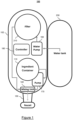
Figure 1 is a top view of a beverage dispensing system; -
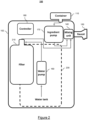
Figure 2 is a front view of the beverage dispensing system ofFigure 1 ; -
Figure 3 is a perspective view comprising additional components of the beverage dispensing system ofFigures 1 and2 ; -
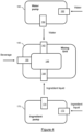
Figure 4 is a functional view of interactions between components of the beverage dispensing system ofFigures 1 and2 ; -
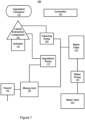
Figure 5 is another functional view of interactions between components of the beverage dispensing system ofFigures 1 and2 ; -
Figure 6 is a schematic representation of a liquid extraction component of the beverage dispensing system ofFigures 1-3 adapted for implementing a self-cleaning procedure; -
Figures 7 ,8 ,9 and10 are schematic representations of the beverage dispensing system ofFigures 1-3 adapted for implementing the self-cleaning procedure; -
Figure 11 is a schematic representation of the beverage dispensing system ofFigure 7 further comprising an air pump; and -
Figure 12 is a schematic representation of the beverage dispensing system ofFigure 7 further comprising an Ultraviolet-C (UV-C) module. - The foregoing and other features will become more apparent upon reading of the following non-restrictive description of illustrative embodiments thereof, given by way of example only with reference to the accompanying drawings.
- The present disclosure aims at providing a compelling alternative to bottled water and other water-based ready-to-drink beverages, by disclosing a new multi-servings beverage dispensing system with self-cleaning capabilities. The beverage dispensing system is meant to offer a convenient, reliable, and cost-effective beverage solution to consumers' beverage needs. The beverage dispensing system is adapted to produce filtered water, as well as other unique beverages, through a container adapted for storing a liquid and allowing extraction of the liquid on-demand. For example, the container stores a liquid concentrate, which is mixed (by the beverage dispensing system) with filtered water, to produce a beverage. Instead of filtered water, the liquid concentrate may be mixed with any of the following: still (not sparkling) water, flavored water, enhanced water, infused water, and an alcoholic drink.
- The beverage dispensing system is adapted to offer the following functionalities and benefits. Providing on-demand filtered water, by filtering the eventual bad taste, unhealthy contaminants or particles present in water. Providing on-demand custom beverages, by preparing a variety of appealing beverages, produced with filtered water, the consumer having the option to control the level of infusion of each beverage. Reducing carbon dioxide (CO2) emissions, by avoiding transport of heavy bottled beverages to the point of consumption. Saving space, by avoiding stockage of voluminous beverage containers (e.g. in a fridge at home or an the office). Providing health benefit, resulting from more convenient and improved hydration options, including better concentration. Providing distribution benefit, the containers being light and valuable enough to be shipped directly to consumers at low shipping costs.
- Furthermore, the beverage dispensing system implements a self-cleaning procedure after each beverage dispensing. The self-cleaning procedure is instantaneous, entirely automated and smoothly integrated with the beverage dispensing phase (the self-cleaning procedure relies on a small number of standard and cost-effective components dedicated to the cleaning phase).
- Reference is now made concurrently to
Figures 1 ,2 ,3 ,4 and5 .Figures 1 and2 are respective top and front views of abeverage dispensing system 100.Figure 3 is a perspective view comprising additional components of thebeverage dispensing system 100 not represented inFigures 1 and2 for simplification purposes.Figures 4 and5 are functional views of interactions between components of thebeverage dispensing system 100. The self-cleaning functionalities of thebeverage dispensing system 100 are not illustrated inFigures 1-4 and will be detailed later in the description. - For simplification purposes,
Figures 1 and2 represent thebeverage dispensing system 100 without components used for the self-cleaning procedure, whileFigures 3 and5 introduce the components used for the self-cleaning procedure (which will be detailed later in relation toFigures 6-12 ). - The
beverage dispensing system 100 comprises a housing 102 (illustrated inFigures 1 ,2 and3 ), a water tank 230 (illustrated inFigures 1 and2 ), a water pump 160 (illustrated inFigures 1 ,2 ,4 and5 ), a water filter 210 (illustrated inFigures 1 and2 ), an ingredient container 110 (illustrated inFigures 1 ,2 ,3 and5 ), aningredient pump 170 illustrated inFigures 1 ,2 ,3 ,4 and5 ), a mixing unit 140 (illustrated inFigures 1 ,2 and4 ), a mixing unit outlet 150 (illustrated as a faucet inFigures 1 ,2 and also illustrated inFigure 4 ), a controller 180 (illustrated inFigures 1 ,2 and5 ), a user control interface 190 (illustrated inFigure 5 ), a liquid extraction tube 120 (illustrated inFigure 3 ) and an actuator 130 (illustrated inFigures 3 and5 ). - The
beverage dispensing system 100 is multi-servings and is adapted for preparing and dispensing a custom beverage. The beverage is prepared by mixing water contained in thewater tank 230 and a liquid contained in theingredient container 110. Examples of liquids contained in theingredient container 110 have been provided previously. Thecontainer 110 is referred to as the ingredient container, since the liquid contained in thecontainer 110 is an ingredient which is mixed with the liquid (generally water) contained in thewater tank 230, to dispense a customized beverage (e.g a beverage having a customized flavor due to the flavor of the ingredient). Thus, the liquid contained in theingredient container 110 will also be referred to as the ingredient liquid. Furthermore, as mentioned previously, thewater tank 230 is not limited to containing water, but may also contain an alcoholic beverage, etc. Thus, although the liquid contained in thewater tank 230 is referred to as water in the rest of the description, thebeverage dispensing system 100 is adapted to process other types of liquids contained in thewater tank 230. - The arrows in
Figures 1 and2 schematically illustrate the respective flows of water and ingredient liquid between components of thebeverage dispensing system 100. Similarly, the arrows inFigure 4 schematically illustrate the respective flows of water, ingredient liquid and beverage involving thewater pump 160, theingredient pump 170 and themixing unit 140. Additional flows related to the self-cleaning functionalities will be detailed later in the description. - The
water tank 230 is generally a removable and refillable water tank, thehousing 102 being adapted for receiving and removing thewater tank 230, as is well known in the art (e.g. in a manner similar to water tanks used for pod based coffee infusers). - In an exemplary implementation, a water tank engaging port (not represented in the Figures for simplification purposes) is mounted on the
housing 102 and connected in liquid communication with a water pump inlet 162 (schematically represented inFigure 4 ) of thewater pump 160. Thewater tank 230 comprises a bottom port (not represented in the Figures for simplification purposes) configured for saleably and removably engaging the water tank engaging port on thehousing 102. Theremovable water tank 230 also comprises a reclosable top opening for allowing a user to fill thewater tank 230 with water. Thus, the water contained in thewater tank 230 is made available to thebeverage dispensing system 100 via thewater pump 160. Alternatively, thewater tank 230 is directly connected to a municipal water network. - The
water pump 160 is mounted inside thehousing 102. Thewater pump 160 comprises the previously mentionedwater pump inlet 162 in liquid communication with thewater source 230 via the previously mentioned water tank engaging port. Thewater pump 160 also comprises a water pump outlet 164 (schematically represented inFigure 4 ) in liquid communication with a mixing unit water inlet 142 (schematically represented inFigure 4 ) of themixing unit 140. This configuration is used when thebeverage dispensing system 100 does not comprise thewater filter 210. - Optionally, the
beverage dispensing system 100 further comprises thewater filter 210 in serial liquid communication between thewater pump 160 and the mixing unit 140 (more specifically in serial liquid communication between the previously mentionedwater pump outlet 164 of thewater pump 160 and the previously mentioned mixingunit water inlet 142 of the mixing unit 140). - In an exemplary implementation, the
water filter 210 is a user selectively removable water filter, and thebeverage dispensing system 100 comprises a removable filter mounting arrangement for removably receiving thewater filter 210. The filter mounting arrangement is generally located along a rear portion of thehousing 102. Thus, after a predetermined usage or volume of filtered water, the user may conveniently proceed with replacing theremovable water filter 210 with a new one. The spent removable water filter may be appropriately recycled or disposed of according to the manufacturer instructions. - The
ingredient container 110 is a removable, single-use or refillable ingredient container. Theingredient container 110 comprises a casing 114 (represented inFigure 3 ) having a sufficient capacity for storing ingredient liquid for one serving or for multi-servings of the custom beverage served by thebeverage dispensing system 100. The ingredient container 110 (in particular the casing 114) can be made of a recyclable material or material(s). - In an exemplary implementation, the
casing 114 comprises a container outlet port 112 (represented inFigure 3 ) through which the liquid stored inside thecasing 114 is extracted. - The
beverage dispensing system 100 further comprises a container engaging inlet port (not represented in the Figures for simplification purposes). The container engaging inlet port is generally mounted along an upper portion of thehousing 102. The container engaging inlet port is adapted for removably engaging theingredient container 110. The respective design of a container engaging inlet port andcorresponding ingredient container 110 allowing removable engagement of theingredient container 110 into the container engaging inlet port is well known in the art of beverage dispensing systems. - In an exemplary implementation, the container engaging inlet port defines a container port engaging cavity (not represented in the Figures for simplification purposes) extending at least slightly inwardly relative to the upper portion of the
housing 102. The container port engaging cavity is suitably sized and configured for removably engaging therein in a snug-fit relation thecontainer outlet port 112 of asuitable ingredient container 110 containing an ingredient liquid. The container engaging inlet port further defines an inlet port guide opening (not represented in the Figures for simplification purposes) extending coaxially centrally and inwardly relative to an innermost surface portion of a container port engaging cavity. - The
liquid extraction tube 120 comprises a substantially elongated tubular member defining a liquid extraction inlet 122 (represented inFigure 3 ), a liquid extraction outlet 124 (represented inFigure 3 ), and a liquid extraction passageway extending there between (not represented in the Figures for simplification purposes). In an exemplary implementation, theliquid extraction tube 120 is a plunger. Adaptation of theliquid extraction tube 120 to the self-cleaning functionalities will be detailed later in the description. - The
liquid extraction tube 120 is slidably mounted inside thehousing 102, so as to be slidably movable between a retracted position and an extended position. In the retracted position, theliquid extraction inlet 122 is retracted within the container engaging inlet port. For example, in the previously mentioned implementation of the container engaging inlet port, theliquid extraction inlet 122 is retracted within the previously mentioned inlet port guide opening of the container engaging inlet port. In the extended position, an end portion of theliquid extraction tube 120, including theliquid extraction inlet 122, protrudes from the container engaging inlet port. - The
actuator 130 is mounted inside the housing 102.Theactuator 130 comprises an actuator drive member 134 (represented inFigure 3 ). Theactuator drive member 134 is connected to theliquid extraction tube 120, and is adapted for moving theliquid extraction tube 120 between its retracted position and its extended position. - The
actuator 130, in cooperation with theliquid extraction tube 120 and the container engaging inlet port, are suitably sized and configured such that, when theingredient container 110 is engaged in the container engaging inlet port and theliquid extraction tube 120 is in the retracted position, theliquid extraction inlet 122 does not contact theingredient container 110. For example, if theingredient container 110 comprises thecontainer outlet port 112, theliquid extraction inlet 122 does not contact thecontainer outlet port 112. When theliquid extraction tube 120 is in the extended position, theliquid extraction inlet 122 longitudinally engages through theingredient container 110, so as to be in liquid communication with the interior of theingredient container 110. For example, if theingredient container 110 comprises thecontainer outlet port 112, theliquid extraction inlet 122 longitudinally engages through thecontainer outlet port 112. - In the implementation illustrated in
Figure 3 , theliquid extraction inlet 122 is a detachable member of theliquid extraction component 120 for facilitating cleaning of theliquid extraction inlet 122. Theliquid extraction inlet 122 is integrated to an upperflexible extension 123 adapted to adhere to theingredient container 110. Theflexible extension 123 prevents leaking of the ingredient liquid stored in theingredient container 110 when theliquid extraction inlet 122 longitudinally engages through theingredient container 110 when moved in the extended position by theactuator 130. However, other implementations of the liquid extraction inlet 122 (e.g. not detachable from theliquid extraction component 120, without the upperflexible extension 123, etc.) are also within the scope of the present disclosure. - The
ingredient pump 170 is mounted inside thehousing 102. Theingredient pump 170 comprises an ingredient pump inlet 172 (represented inFigures 3 and4 ) in liquid communication with theliquid extraction outlet 124 of theliquid extraction tube 120. A liquid conduit 171 (represented inFigure 3 ) interconnects theingredient pump 170 with the mixing unit 140 (not represented inFigure 3 for simplification purposes). Theingredient pump 170 also comprises an ingredient pump outlet 174 (schematically represented inFigure 4 ) in liquid communication with a mixing unit ingredient inlet 144 (schematically represented inFigure 4 ) of themixing unit 140. - In an exemplary implementation, the
ingredient pump 170 is a peristaltic pump. Peristaltic pumps are well known in the art, particularly in medical contexts. Peristaltic pumps generally comprise a flexible and resilient liquid conduit in liquid communication between theingredient pump inlet 172 andingredient pump outlet 174. Peristaltic pumps further comprise a rotating actuator applying a cyclical pressure in a direction along a portion of the flexible conduit, so as to force a liquid flow in the ingredient liquid present in the conduit. - Similarly to medical contexts, the peristaltic pump is used in the context of the present
beverage dispensing system 100 for its capability to controllably deliver a relatively small and precise flow of ingredient liquid, as well as for its ease of cleaning (since there is no turbine, piston or moving parts in contact with the pumped liquid). - The
mixing unit 140 is mounted inside thehousing 102. Themixing unit 140 comprises an internal mixing unit chamber 148 (schematically represented inFigure 4 ), the mixingunit water inlet 142, the mixingunit ingredient inlet 144. Themixing unit 140 further comprises the mixing unit outlet 150 (schematically represented inFigure 4 ) connected to themixing unit 140 and extending forward from a front surface portion of thehousing 102.Figures 1 and2 illustrate an exemplary implementation of the mixingunit outlet 150 consisting of a faucet. - Each one of the mixing
unit water inlet 142, mixingunit ingredient inlet 144 and mixingunit outlet 150, is in liquid communication with the interior of the mixingunit chamber 148. The mixingunit outlet 150 comprises an output opening that is suitably adapted for pouring the content of the mixingunit chamber 148 into an underlying user cup or bottle. - The
controller 180 is mounted inside thehousing 102. Thecontroller 180 is suitably operatively connected and adapted for operatively controlling thewater pump 160, theingredient pump 170, and theactuator 130.Figure 5 provides a schematic representation of the interactions of thecontroller 180 with other components (e.g. thewater pump 160, theingredient pump 170 and the actuator 130) of thebeverage dispensing system 100. - Interactions with a
cleaning pump 220, optionally with an Ultraviolet-C (UV-C)module 240 and optionally with anair pump 250 are also represented inFigure 5 . These three components are related to the self-cleaning functionalities and will be detailed later in the description. - In an exemplary implementation, the
controller 180 consists of any suitable electronic microcontroller. Thecontroller 180 comprises at least some of the following components (not represented inFigure 5 for simplification purposes): one or more processor, memory, interface inputs and outputs (I/O), and communication capabilities that are generally found in known beverage dispensing systems. Examples of communication capabilities comprise a wireless communication interface (e.g. Bluetooth®, Bluetooth Low Energy (BLE), Wi-Fi, Near Field Communication (NFC), etc.), a wired communication interface (e.g. Ethernet, etc.), or a combination thereof. - The user control interface 190 (schematically represented in
Figure 5 , but not represented inFigures 1 and2 for simplification purposes) is mounted on thehousing 102 and is in operative communication with thecontroller 180. Theuser control interface 190 comprises at least one of a button and Light Emitting Diodes (LEDs), a touch actuated user interface located on thehousing 102, a voice actuated user interface mounted inside thehousing 102, a remote user interface accessible through a mobile application or equivalent executed on aremote computing device 400 and communicating with thecontroller 180 through a wired or wireless communication link, or a combination thereof. Theuser control interface 190 may also comprise a display (e.g. a basic screen, a touch screen allowing interactions with the user, etc.) for displaying information related to the operations of thebeverage dispensing system 100. - In an exemplary implementation, the user control interface 190 (comprising buttons and LEDs) is partly accessible along a front surface portion of the
housing 102 and the mixing unit outlet (e.g. faucet) 150. - The
user control interface 190 and thecontroller 180 are suitably adapted and configured for at least enabling the user to select a custom beverage, and actuate a start command, either simultaneously or consecutively with the selection of the custom beverage, so as to efficiently mix and deliver the desired custom beverage through the mixing unit outlet (e.g. faucet) 150. - Additional information is usually selectable by the user through the
user control interface 190 such as, but not limited to, a desired volume of beverage, a desired intensity of flavor, selecting to be simply served water, etc. - Functionalities of the
user control interface 190 may be accomplished (at least partially) through any suitable remote communication arrangements and software applications in cooperative operational relation with thecontroller 180 and/oruser control interface 190. For this purpose, a remote computing device 400 (schematically represented inFigure 5 ) interfaces with thecontroller 180 and/oruser control interface 190 via the communication interface of thecontroller 180. Examples ofremote computing devices 400 comprise a smartphone, a tablet, a laptop, a table top computer, etc. - Following is an exemplary sequence of operations of the
beverage dispensing system 100 managed via theuser control interface 190 and thecontroller 180. When thebeverage dispensing system 100 is powered on, provided with water in thewater tank 230, and a user selectedingredient container 110 is engaged in the container engaging inlet port on thehousing 102, a user may position a cup or bottle under the mixing unit outlet (e.g. faucet) 150, select a custom beverage through theuser control interface 190, and actuate a start command of the beverage dispensing system 100 (the selection and actuation are performed either consecutively or simultaneously). - Following the start command, the
controller 180 automatically determines a suitable time and speed of operation of thewater pump 160, and a suitable time and speed of operation of theingredient pump 170, according to the custom beverage selected by the user. Thecontroller 180 also automatically determines suitable operating parameters of the actuator 130 (e.g. direction of movement, suitable time and speed of operation for each movement, etc.). Once the determinations are completed, thecontroller 180 applies corresponding commands to bothpumps actuator 130, so as to efficiently mix and deliver the desired custom beverage through the mixing unit outlet (e.g. faucet) 150. - Thus, a user may advantageously select to be served a differently flavored custom beverage as desired, by simply engaging in the container engaging inlet port of the beverage dispensing system 100 a
removable ingredient container 110 corresponding to the desired flavor. Alternatively, the user may simply select to be served plain water of the water tank 230 (in which case theingredient pump 170 is not activated by the controller 180). - Optionally, the
beverage dispensing system 100 further comprises liquid flow measuring means capable of providing a liquid flow measure of the ingredient liquid entering themixing unit 140 through the mixingunit ingredient inlet 144. - In a first exemplary implementation, the liquid flow measuring means consists of a time based liquid measuring algorithm executed by the
controller 180, based on the operating time of theingredient pump 170 and a predetermined viscosity value of the ingredient liquid in theingredient container 110. - In a second exemplary implementation, the liquid flow measuring means consists of a liquid flow meter (not represented in the Figures for simplification purposes) in operative communication with the
controller 180. The liquid flow meter measures the flow of liquid circulating from theingredient container 110 towards the mixingunit 140. For example, the liquid flow meter is coupled in serial liquid communication between theliquid extraction inlet 122 of theliquid extraction tube 120 and themixing unit 140. Thecontroller 180 instantly actuates theingredient pump 170 at a predetermined speed of operation following the start command, and determines the remaining time and speed of operation of theingredient pump 170, based on the real time liquid flow measurements provided by the liquid flow meter. Thus, the estimated ingredient liquid volume actually delivered into themixing unit 140 takes into account the current viscosity, fluidity and/or temperature of the ingredient liquid contained in theremovable ingredient container 110. - Optionally, consumer data, operational data, statistics and/or maintenance information are exchanged between the
controller 180 and a customer database on a remote computing device 400 (e.g. a server), via the communication capabilities provided by thecontroller 180. - Optionally, the
beverage dispensing system 100 comprises a contactless data reader 195 (schematically represented inFigure 5 , but not represented inFigures 1 and2 for simplification purposes) in operative communication with the controller 180 (or directly integrated to the controller 180). Thecontactless data reader 195 allows thecontroller 180 to read data from theingredient container 110 engaged in the container engaging inlet of thebeverage dispensing system 100. Optionally, theingredient container 110 comprises a component 115 (schematically represented inFigure 5 ) capable of storing the data and allowing reading of the data by thecontactless data reader 195. Thecomponent 115 will be referred to as a tag in the following. - In an exemplary implementation, the
contactless data reader 195 comprises a barcode reader or a quick response (QR) code reader. In an exemplary configuration, the reader is mounted on thehousing 102 and is substantially adjacent to the container engaging inlet port. A compatiblebar code tag 115 orQR code tag 115 is integrated to theingredient container 110. In an exemplary configuration, thetag 115 is located along a plane portion of theingredient container 110. Thetag 115 is further positioned so as to allow reading by the bar code reader or QR code reader mounted on thehousing 102. - In an alternative or complementary exemplary implementation, the
contactless data reader 195 comprises a Radio Frequency Identification (RFID) reader. A corresponding read or read/write RFID tag 115 is integrated to theingredient container 110. - Examples of data stored by the
tag 115 comprise at least some of the following information related to the ingredient liquid present in the ingredient container 110: type of ingredient liquid, flavor, viscosity, density, temperature, remaining level of ingredient liquid in theingredient container 110, etc. As mentioned previously, thecontactless data reader 195 integrated into thebeverage dispensing system 100 is capable of reading the information stored via the tag. Optionally, thetag 115 provides the capability of modifying the information stored by thetag 115. In this case, thecontactless data reader 195 is also capable of transferring data to thetag 115, to modify at least some of the information stored by thetag 115. - The information collected from or exchanged with the
tag 115 can be used by thecontroller 180 to more accurately determine the appropriate time and speed of operation of theingredient pump 170, to simplify the choices or information needed to be entered by the user via theuser control interface 190, etc. Furthermore, some of the information collected from or exchanged with thetag 115 can be displayed on the display of the user control interface 190 (when theuser control interface 190 comprises one). - Information used for the implementation of the self-cleaning procedure, which will be detailed later in the description, can also be stored by the
tag 115. - Optionally, the
controller 180 implements a machine learning algorithm (e.g. a neural network) to make decision(s) based on (at least) some of the information stored by thetag 115. For example, in the case of a neural network, a predictive model of the neural network is stored in the memory of thecontroller 180. The predictive model has been generated during a training phase, using a large amount of training data. When ready, the predictive model is transmitted to thecontroller 180 via its communication interface and stored in its memory. Using the predictive model, the neural network is capable of predicting the most effective time and / or speed of operation of theingredient pump 170 based on relevant information read from the tag 115 (e.g. at least some of the type of ingredient, viscosity, density, temperature, remaining level of ingredient liquid, etc.). - The same (or a complementary) predictive model can also be used for predicting the most effective operating parameters for the implementation of the self-cleaning procedure, which will be detailed later in the description.
- In an alternative implementation, the
tag 115 is comprised in a cap (which will be detailed later in the description) for theingredient container 110. - Although not represented in the Figures for simplification purposes, an electrical power source powers the components of the
beverage dispensing system 100 which need power to operate (thewater pump 160, theingredient pump 170, thecontroller 180, theuser control interface 190, etc.). - The electrical power source may be any suitable electrical power source such as, for example, a 110 Volts Alternative Current (AC) outlet providing electrical power to the components of the
system 100 through a conventional control switch and extension cord arrangement, a rechargeable battery mounted inside thehousing 102, or a combination thereof. - Furthermore, suitable tubing, molded liquid networks, or a combination thereof, may provide the liquid communications between the various components of the
beverage dispensing system 100 as described above. - Details of the implementation of the
ingredient container 110 are out of the scope of the present disclosure.US patent application 18/063,156 (published asUS 20240010421A1 ) provides several exemplary implementations of theingredient container 110. - Reference is now made concurrently to
Figures 5 ,6 ,7 ,8 ,9 and10 , whereFigures 6 ,7 ,8 ,9 and10 schematically represent the beverage dispensing system 100 (previously described in relation toFigures 1-5 ) being adapted for performing the self-cleaning procedure after each serving of a beverage. - The self-cleaning procedure allows to clean and purge components of the
beverage dispensing system 100, to avoid the risks of having ingredient liquid remaining in the beverage dispensing system 100 (more specifically, remaining in other components than the ingredient container 110) between two servings of a beverage. The self-cleaning procedure also prevents microbiological development in thebeverage dispensing system 100. - The
water tank 230,water pump 160,water filter 210,ingredient container 110,actuator 130,ingredient pump 170, mixingunit 140, mixing unit outlet 150 (illustrated as a faucet in the Figures) andcontroller 180 have been described previously in relation toFigures 1-5 . - The
beverage dispensing system 100 further comprises the cleaning pump 220 (previously introduced in relation toFigures 3 and5 ) for performing the self-cleaning procedure. In an exemplary implementation, thecleaning pump 220 is a peristaltic pump, with characteristics similar to those of theingredient pump 170. A liquid conduit 221 (represented inFigure 3 only for simplification purposes) interconnects thecleaning pump 220 with thewater filter 210, either directly or indirectly through a water conduit connecting thewater filter 210 to themixing unit 140. If thewater filter 210 is not present, theliquid conduit 221 interconnects thecleaning pump 220 with thewater pump 160, through a water conduit connecting thewater pump 160 to themixing unit 140. In all of the previously described configurations, thecleaning pump 220 is in direct or indirect liquid communication with thewater pump 160, to transfer liquid from thewater tank 230 to thecleaning pump 220 through the water pump 160 (and through thewater filter 210 if present). Theliquid conduit 221 may also be directly connected to thewater tank 230. - The
liquid extraction component 120 is adapted to perform the self-cleaning procedure, by being in liquid communication with thecleaning pump 220. More specifically, theliquid extraction component 120 comprises a cleaning water inlet 126 (represented inFigure 3 and schematically represented inFigure 6 ) in liquid communication with thecleaning pump 220, via a liquid conduit 222 (represented inFigure 5 but not represented inFigure 6 for simplification purposes). Theliquid extraction component 120 is designed to let ingredient liquid or air flow from theliquid extraction inlet 122 to theliquid extraction outlet 124; and to allow cleaning water flow from the cleaningwater inlet 126 to theliquid extraction outlet 124. -
Figure 3 illustrates an implementation where the cleaningwater inlet 126 extends horizontally and theliquid extraction outlet 124 extends vertically. However, other geometric configurations are possible, to adapt to the respective positions and designs of other components of thebeverage dispensing system 100. For example, in another configuration not represented in the Figures, the cleaningwater inlet 126 and theliquid extraction outlet 124 extend horizontally. - More generally, the design of the
liquid extraction component 120 is not limited to the implementation described in the present disclosure and illustrated inFigure 3 . Any design of theliquid extraction component 120 allowing to perform the beverage dispensing and the self-cleaning procedures described in the following paragraphs is within the scope of the present disclosure. - Liquid conduits interconnecting the
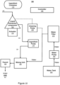
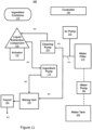
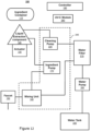
water tank 230 and thewater pump 160, thewater pump 160 and thewater filter 210, thewater filter 210 and themixing unit 140, thewater filter 210 and thecleaning pump 220, thecleaning pump 220 and theliquid extraction component 120, theliquid extraction component 120 and theingredient pump 170, theingredient pump 170 and themixing unit 140, themixing unit 140 and thefaucet 150, are schematically represented in full lines inFigure 7 . InFigures 8 ,9 and10 , the liquid conduits schematically represented inFigure 7 are represented with dashed lines when liquid is circulating therethrough and with arrows indicating the direction of circulation when fluid (liquid or air) is circulating therethrough. - The self-cleaning procedure is performed each time a beverage dispensing occurs, at the end of the beverage dispensing procedure, so that the water used for the self-cleaning process is added to the beverage dispensed through the faucet 150 (e.g. in a glass or bottle placed under the faucet 150). Following is a description of the beverage dispensing and self-cleaning procedures, which are controlled by the
controller 180. - The
controller 180 executes a control software in charge of implementing the aforementioned procedures, by sending commands to the various components of thebeverage dispensing system 100 under its control. The execution of the control software and sending of the commands will be referred to as thecontroller 180 commanding the various components to perform their respective tasks. - Referring more specifically to
Figures 3 ,5 and8 , following is a simplified description of the beverage dispensing procedure (this procedure has already been described in detail previously). The following actions are taken when executing the beverage dispensing procedure. - Action 1: the
controller 180 commands theactuator 130 to move theliquid extraction component 120 upwardly inside theingredient container 110, in the extended position of theliquid extraction component 120. In its extended position, theliquid extraction component 120 is in contact with the ingredient liquid stored in theingredient container 110. - Action 2: the
controller 180 commands thewater pump 160 to transfer water from thewater tank 230 to themixing unit 140 through thewater filter 210. As already mentioned previously, in an alternative configuration, thewater filter 210 is not present and the water is transferred directly from thewater tank 230 to the mixing unit 140 (thewater pump 160 connects directly thewater tank 230 to the mixing unit 140). - Action 3: the
controller 180 commands theingredient pump 170 to extract (by exerting a suction) ingredient liquid from theingredient container 110 via theliquid extraction component 120 and to transfer the extracted ingredient liquid from theliquid extraction component 120 to themixing unit 140. Under the action of theingredient pump 170, the beverage resulting from mixing the ingredient liquid with the water in themixing unit 140, is further transferred to, and dispensed by, thefaucet 150. - The order of actions 1, 2 and 3 may vary based on the implementation of the beverage dispensing procedure. During the beverage dispensing procedure, the
cleaning pump 220 is not active (no water is transferred to theliquid extraction component 120. - After a beverage has been served (according to the aforementioned beverage dispensing procedure), the
controller 180 commands theactuator 130 to move theliquid extraction component 120 downwardly to disengage from theingredient container 110, in the retracted position of theliquid extraction component 120. In its retracted position, theliquid extraction component 120 is no longer in contact with the ingredient liquid stored in theingredient container 110. Optionally, thecontroller 180 also commands thewater pump 160 and theingredient pump 170 to stop (e.g. for a short period of time before starting the self-cleaning procedure). - Referring more specifically to
Figures 3 ,5 ,9 and10 , following is a description of the self-cleaning procedure. - After a beverage has been served (according to the aforementioned beverage dispensing procedure), the self-cleaning procedure is performed. The self-cleaning procedure is based on the following two functionalities: water cleaning functionality (illustrated in
Figure 9 ) and air cleaning functionality (illustrated inFigure 10 ). When performing the self-cleaning procedure, theliquid extraction component 120 is in the retracted position (no longer in contact with the ingredient liquid stored in the ingredient container 110). - The following actions are taken when executing the water cleaning functionality. Water circulating through the
cleaning pump 220 to themixing unit 140 via theliquid extraction component 120 and theingredient pump 170 is referred to as cleaning water, since this circulation of water only occurs during the cleaning procedure. - Action 1: the
controller 180 commands thewater pump 160 to transfer water from thewater tank 230 to the mixing unit 140 (through thewater filter 210 when present as illustrated inFigure 9 ). - Action 2: the
controller 180 commands thecleaning pump 220 to transfer cleaning water from thewater tank 230 to the liquid extraction component 120 (through thewater filter 210 when present). - Action 3: the
controller 180 commands theingredient pump 170 to transfer the cleaning water from theliquid extraction component 120 to themixing unit 140. Under the action of theingredient pump 170, the cleaning water resulting from mixing the cleaning water transferred by theingredient pump 170 from theliquid extraction component 120 and the water transferred by thewater pump 160 from the water tank 230 (though thewater filter 210 if present), is further transferred to, and dispensed by, thefaucet 150. - The order of actions 1, 2 and 3 may vary based on the implementation of the water cleaning functionality. However, in the configuration illustrated in
Figure 9 , thewater pump 160 and thecleaning pump 220 need to be activated simultaneously to circulate cleaning water through theliquid extraction component 120. In an alternative configuration (not represented in the Figures), thecleaning pump 220 can be directly connected to thewater tank 230, in which case it can be operated independently of thewater pump 160. - For each action (1, 2 and 3), the speed of the corresponding pump (160, 220 or 170) is set to a given value (which determines a corresponding flow rate of fluid through the pump). The given speed value of each pump (160, 220 and 170) is transmitted via the respective commands sent by the
controller 180. The speed of each pump (160, 220 and 170) remains constant during the execution of the water cleaning functionality. Alternatively, the speed of at least one of the pumps (160, 220 or 170) varies during the execution of the water cleaning functionality. - The pumps (160, 220 and 170) are active for the same duration corresponding to the duration of the execution of the water cleaning functionality. Alternatively, at least one of the pumps (160, 220 or 170) is not active during the entire duration of the execution of the water cleaning functionality. For example, one of the pumps becomes active a certain time after the beginning of the execution of the water cleaning functionality, becomes inactive a certain time before the end of the execution of the water cleaning functionality, etc.
- When any of the pumps (160, 220 or 170) no longer needs to be active, the
controller 180 commands the pump to stop. At least, at the end of the execution of the water cleaning functionality, the three pumps (160, 220 and 170) become inactive. - The circulation of cleaning water cleans the
liquid extraction component 120, theingredient pump 170, themixing unit 140 and thefaucet 150. The liquid conduits interconnecting theliquid extraction component 120 and theingredient pump 170, theingredient pump 170 and themixing unit 140, themixing unit 140 and thefaucet 150, are also cleaned by the circulation of cleaning water. - The following actions are taken when executing the air cleaning functionality.
- Action 1: the
controller 180 commands thewater pump 160 to transfer water from thewater tank 230 to the mixing unit 140 (through thewater filter 210 when present as illustrated inFigure 9 ). - Action 2: the
controller 180 commands theingredient pump 170 to transfer air through theliquid extraction component 120 to themixing unit 140. The air is sucked into theliquid extraction component 120 via theliquid extraction inlet 122. Under the action of theingredient pump 170, the air transferred by theingredient pump 170 from theliquid extraction component 120 and the water transferred by thewater pump 160 from the water tank 230 (though thewater filter 210 if present), are further transferred to, and dispensed by, thefaucet 150. - The order of actions 1 and 2 may vary based on the implementation of the air cleaning functionality. The
cleaning pump 220 is not active during the execution of the air cleaning functionality. - For each action (1 and 2), the speed of the corresponding pump (160 or 170) is set to a given value (which determines a corresponding flow rate of fluid through the pump). The given speed value of each pump (160 and 170) is transmitted via the respective commands sent by the
controller 180. The speed of each pump (160 and 170) remains constant during the execution of the air cleaning functionality. Alternatively, the speed of at least one of the pumps (160 or 170) varies during the execution of the air cleaning functionality. - The pumps (160 and 170) are active for the same duration corresponding to the duration of the execution of the air cleaning functionality. Alternatively, at least one of the pumps (160 or 170) is not active during the entire duration of the execution of the air cleaning functionality. For example, one of the pumps becomes active a certain time after the beginning of the execution of the air cleaning functionality, becomes inactive a certain time before the end of the execution of the air cleaning functionality, etc.
- When any of the pumps (160 or 170) no longer needs to be active, the
controller 180 commands the pump to stop. At least, at the end of the execution of the air cleaning functionality, the two pumps (160 and 170) become inactive. - The circulation of air cleans the
liquid extraction component 120, theingredient pump 170, themixing unit 140 and thefaucet 150. The liquid conduits interconnecting theliquid extraction component 120 and theingredient pump 170, theingredient pump 170 and themixing unit 140, themixing unit 140 and thefaucet 150, are also cleaned by the circulation air. The simultaneous circulation of water in themixing unit 140, thefaucet 150 and the liquid conduit interconnecting themixing unit 140 and thefaucet 150 improves the evacuation of residues detached by the circulation of air. - Optionally, action 1 is not performed when executing the air cleaning functionality, so that no water is not circulated during the procedure. In this case, action 2 results in sucking air through the
liquid extraction component 120 towards the mixingunit 140, the air being further transferred to, and dispensed by, thefaucet 150. - The self-cleaning procedure comprises the execution of at least one of the water cleaning functionality and the air cleaning functionality. The self-cleaning procedure generally comprises (but is not limited to) a sequence of execution of multiple instances of any one of the water cleaning functionality and the air cleaning functionality, two consecutive instances being optionally separated by a time interval. The sequence may start with the water cleaning functionality or the air cleaning functionality. An instance of the water cleaning functionality is generally followed by an instance of the air cleaning functionality. However, several consecutive instances of the water cleaning functionality may be executed before an instance of the air cleaning functionality. Similarly, an instance of the air cleaning functionality is generally followed by an instance of the water cleaning functionality. However, several consecutive instances of the air cleaning functionality may be executed before an instance of the water cleaning functionality. The self-cleaning procedure may also comprise one or more instances of the air cleaning functionality only or one or more instances of the water cleaning functionality only.
- The water cleaning and air cleaning functionalities can be defined by the respective speeds of the
water pump 160,ingredient pump 170 and cleaningpump 220; as well as optional time intervals when all the pumps remain idle. - For example, the sequence is defined by:
- N (e.g. 10) repetitions of a first cycle (1);
- optionally followed by a time interval T (e.g. 2 milliseconds, but could also be null) where the
pumps - followed by M (e.g. 4) repetitions of a second cycle (2).
- Cycle 1 comprises:
- for a time interval t1 (e.g. 100 milliseconds): operate the
water pump 160 at speed v1, operate thecleaning pump 220 at speed v2 and operate theingredient pump 170 at speed v3; - optionally having
pumps - for a time interval t3 (e.g. 100 milliseconds): operate the
water pump 160 at speed v4, operate thecleaning pump 220 at speed v5 and operate theingredient pump 170 at speed v6; - optionally having
pumps - For example, v1, v2 and v3 are set to values (e.g. respectively 35%, 0% and 100% of their maximum capacity) implementing the air cleaning functionality; while v4, v5 and v6 (e.g. respectively 35%, 75% and 100% of their maximum capacity) are set to values implementing the water cleaning functionality.
- Cycle 2 comprises:
- for a time interval t5 (e.g. 50 milliseconds): operate the
water pump 160 at speed v7, operate thecleaning pump 220 at speed v8 and operate theingredient pump 170 at speed v9; - optionally having
pumps - for a time interval t7 (e.g. 25 milliseconds): operate the
water pump 160 at speed v10, operate thecleaning pump 220 at speed v11 and operate theingredient pump 170 at speed v12; - optionally having
pumps - For example, v7, v8 and v9 are set to values (e.g. respectively 35%, 0% and 100% of their maximum capacity) implementing the air cleaning functionality; while v10, v11 and v12 are set to values (e.g. respectively 35%, 0% and 100% of their maximum capacity) implementing the water cleaning functionality.
- The sequence performing the self-cleaning procedure, which occurs just after a beverage preparation and serving, is referred to as the first sequence. Optionally, one or more additional sequences are performed after respective pre-determined interval(s) of time, if no new beverage preparation and serving occurs. For example, a second sequence occurs 3 hours after the beverage preparation and serving, and a third sequence is performed 2 hours after the second sequence (if no beverage has been prepared and served in the meantime). The second and third sequences have their own execution parameters (speed of the pumps, number of repetitions, idle time intervals, etc.), as was previously described with the exemplary implementation of the first sequence.
- To implement the beverage dispensing and self-cleaning procedures, the
controller 180 automatically determines operating parameters (e.g. suitable activation time, speed of operation, time in operation, etc.) for thewater pump 160, theingredient pump 170 and thecleaning pump 220. Thecontroller 180 also automatically determines suitable operating parameters of the actuator 130 (e.g. direction of movement, suitable time and speed of operation for each movement, etc.). Based on these determinations, the corresponding control commands are respectively sent to thewater pump 160, theingredient pump 170, thecleaning pump 220 and theactuator 130. - Furthermore, as mentioned previously in relation to
Figure 5 , data related to thecontainer 110 may be stored by thetag 115. In an exemplary implementation, data stored by thetag 115 are used by thecontroller 180 for determining one or more operating parameters of at least one of thewater pump 160, theingredient pump 170, thecleaning pump 220 and theactuator 130. The one or more operating parameters are used for implementing at least one of the beverage dispensing and the self-cleaning procedures. This allows a customization of the implementation of the beverage dispensing procedure and / or self-cleaning procedure, based on a given type ofcontainer 110 being used. The given type ofcontainer 110 being used stores a given type of liquid ingredient, different from other type(s) of liquid ingredient(s) stored in other type(s) of container. Thebeverage dispensing system 110 supports (and adapts to) the various types of containers storing the various types of liquid ingredients, by customizing the beverage dispensing procedure and / or the self-cleaning procedure based on the parameters stored in thetag 115. - The previously described self-cleaning procedure has several advantages, resulting from its close integration with the beverage dispensing procedure. The cleaning procedure is performed each time a beverage dispensing procedure occurs. The cleaning water resulting from the cleaning procedure is added to the beverage, by performing the cleaning procedure just after completion of the beverage dispensing procedure. Consequently, the cleaning water does not need to be disposed of. The self-cleaning procedure allows the usage of containers storing different ingredient liquids, without risking contamination of a currently dispensed beverage using an ingredient liquid stored in a container, by another ingredient liquid (stored in another container) used for a previously dispensed beverage.
- Moreover, the self-cleaning procedure is also beneficial with respect to the water filtration functionality of the
system 100, implemented when thewater filter 210 is present. During filtration, significant amounts of chlorine and other substances used in tap water to ensure its safety are removed. While this improves the taste and quality of the filtered water, it also creates conditions where bacteria, mold, or fungi could develop more easily in the system. By incorporating an automated cleaning or drainage mode (such as the presently described self-cleaning procedure), thesystem 100 ensures that these risks are mitigated, maintaining the hygiene and safety of the water, and extending the overall lifespan of the filtration components. - Optionally, a dedicated cleaning container can be used, to perform a deeper cleaning of the
beverage dispensing system 100, once in a while (e.g. after a pre-defined number of occurrences of beverage dispensing has occurred). The cleaning container stores a cleaning liquid which is circulated in theliquid extraction component 120,ingredient pump 170, mixingunit 140 andfaucet 150 during the beverage dispensing procedure. The self-cleaning procedure evacuates potential remnants of the cleaning liquid circulated during the beverage dispensing procedure. Examples of cleaning liquid include water, water mixed with cleaning product(s), etc. - Reference is now made concurrently to
Figures 5 and11 . Thebeverage dispensing system 100 illustrated inFigure 11 comprises all the previously described components, and further comprises the air pump 250 (previously introduced in relation toFigure 5 ). Theair pump 250 is optional and aims at complementing the previously described self-cleaning procedure, by performing a drying procedure. -
Figure 11 illustrates theair pump 250 being connected to theliquid conduit 251 connecting thewater filter 210 to both thecleaning pump 220 and themixing unit 140. - The drying procedure is performed by a simultaneous activation of the
air pump 250, thecleaning pump 220 and theingredient pump 170, to circulate air in thecleaning pump 220, theliquid extraction component 120, theingredient pump 170, themixing unit 140 and thefaucet 150; and in all the liquid conduits interconnecting these components. The circulation of air dries the aforementioned components and liquid conduits, ensuring a minimum level of humidity to avoid proliferation of microorganisms. - The
air pump 250 is controlled by thecontroller 180 in a manner similar to the previously described control of the other pumps. The localization of theair pump 250 may vary, based on a particular implementation of thebeverage dispensing system 100. - The drying procedure can be performed at any time, including just after one of the previously described sequences of the self-cleaning procedure, an interval of time (e.g. 1 minute) after one of the previously described sequences of the self-cleaning procedure, etc. The drying procedure can also be integrated to one of the previously described sequences of the self-cleaning procedure.
- Reference is now made concurrently to
Figures 5 and12 . Thebeverage dispensing system 100 illustrated inFigure 12 comprises all the previously described components, and further comprises the UV-C module 240 (previously introduced in relation toFigure 5 ). The UV-C module 240 is optional and aims at complementing the previously described self-cleaning procedure. - As is well known in the art, the UV-
C module 240 emits UV-C radiations, which have the property to eliminate microbial pathogens when operated at a pre-defined wavelength. Such microbial pathogens may develop on internal walls of components of thebeverage dispensing system 100, where water or ingredient liquid circulate. In an exemplary implementation, the UV-C module comprises an UV-C led operating at the pre-defined wavelength. - The UV-
C module 240 is positioned within thebeverage dispensing system 100, so that the emitted UV-C radiations cover a givenarea 245 within thebeverage dispensing system 100. For illustration purposes, thearea 245 illustrated inFigure 12 includes thecleaning pump 220, theingredient pump 170 and themixing unit 140. However, additional components such as thewater pump 160 and / or theliquid extraction component 120 may be included in thearea 245. Furthermore, liquid conduits interconnecting the aforementioned components are also at least partially included in the area 245 (e.g. liquid conduit between the cleaningpump 220 and theliquid extraction component 120, liquid conduit between theingredient pump 170 and themixing unit 140, etc.). - The representation of the
area 245 inFigure 12 is schematic, and only aims at illustrating which components of thebeverage dispensing system 100 are covered (at least partially) by the UV-C radiations. In reality, the area covered by the UV-C radiations is a three-dimensional (3D) shape, for example a cone extending downwardly from the UV-C module 240. - The design of the beverage dispensing system 100 (e.g. size, shape and positioning of various components) can be adapted so that the targeted components are included in the
area 245. Furthermore, the targeted components (e.g. pumps 170 and 220, liquid conduits, etc.) need to be made of a material allowing transmission of the UV-C radiations, so that microbial pathogens on internal walls of the targeted components can be eliminated. - The UV-
C module 240 is activated after each beverage dispensing procedure, which has been described previously. For example, the UV-C module 240 is activated during and / or after completion of the previously described self-cleaning procedure. - Operations of the UV-
C module 240 are controlled by thecontroller 180. For instance, thecontroller 180 determines when to command the UV-C module 240 to emit UV-C radiations and for which duration. For example, the duration of emission of the UV-C radiations is determined based on the wavelength of the UV-C radiations and the irradiance needed for efficiently eliminating microbial pathogens (e.g. eliminating 99.9% of the microbial pathogens). - Although the present disclosure has been described hereinabove by way of non-restrictive, illustrative embodiments thereof, these embodiments may be modified at will within the scope of the appended claims without departing from the spirit and nature of the present disclosure.
Claims (15)
- A self-cleaning multi-servings beverage dispensing system (100) adapted for preparing and serving a beverage, the system comprising:a container engaging inlet port adapted for removably engaging a container (110) storing an ingredient liquid;a liquid extraction component (120) slidably movable between a retracted position and an extended position, the liquid extraction component (120) not being in contact with the ingredient liquid when the container (110) is engaged in the container engaging inlet port and the liquid extraction component (120) is in the retracted position, the liquid extraction component (120) being in contact with the ingredient liquid when the container (110) is engaged in the container engaging inlet port and the liquid extraction component (120) is in the extended position;an actuator (130) adapted for moving the liquid extraction component (120) between the retracted position and the extended position;an ingredient pump (170) for extracting at least some of the ingredient liquid from the container (110) via the liquid extraction component (120) when the liquid extraction component (120) is in the extended position and the container (110) is engaged in the container engaging inlet port, and transferring the extracted ingredient liquid from the liquid extraction component (120) to a mixing unit (140);a water tank (230) for storing water;a water pump (160) for transferring water from the water tank (230) to the mixing unit (140);the mixing unit (140) for receiving and mixing the ingredient liquid transferred to the mixing unit (140) and the water transferred to the mixing unit (140);a mixing unit outlet (150) for pouring a content of the mixing unit (140);a cleaning pump (220) for transferring cleaning water from the water tank (230) to the liquid extraction component (120); anda controller (180) comprising electronic means for controlling operations of the beverage dispensing system (100), the controller (180) being adapted to perform a self-cleaning procedure by sending commands to the cleaning pump (220), the water pump (160) and the ingredient pump (170) to execute at least one of:an air cleaning functionality comprising:
a transfer of air by the ingredient pump (170) through the liquid extraction component (120) to the mixing unit (140), the air being sucked into the liquid extraction component (120) via the liquid extraction inlet (122); anda water cleaning functionality comprising:a transfer of water by the water pump (160) from the water tank (230) to the mixing unit (140);a transfer of cleaning water by the cleaning pump (220) from the water tank (230) to the liquid extraction component (120); anda transfer of the cleaning water by the ingredient pump (170) from the liquid extraction component (120) to the mixing unit (140). - The self-cleaning multi-servings beverage dispensing system of claim 1, wherein the air cleaning functionality further comprises a transfer of water by the water pump (160) from the water tank (230) to the mixing unit (140).
- The self-cleaning multi-servings beverage dispensing system of claim 1, wherein the liquid extraction component (120) further comprises a liquid extraction outlet (124) adapted for transferring any of the ingredient liquid, the cleaning water and the air to the mixing unit (140); and the liquid extraction component (120) further comprises a cleaning water inlet (126) adapted for receiving the cleaning water from the cleaning pump (220).
- The self-cleaning multi-servings beverage dispensing system of claim 1, wherein the cleaning pump (220) is in direct or indirect liquid communication with the water pump (160).
- The self-cleaning multi-servings beverage dispensing system of claim 1, further comprising a water filter (210), the water pump (160) being in liquid communication with the water tank (230) and the water filter (210), the mixing unit (140) being in liquid communication with the water filter (210), and the cleaning pump (220) being in liquid communication with the water filter (210).
- The self-cleaning multi-servings beverage dispensing system of claim 1, wherein performing the self-cleaning procedure comprises repeating N iterations of: an execution of the air cleaning functionality followed by an execution of the water cleaning functionality or an execution of the water cleaning functionality followed by an execution of the air cleaning functionality, N being an integer greater than 0.
- The self-cleaning multi-servings beverage dispensing system of claim 1, wherein performing the self-cleaning procedure comprises:an execution of the air cleaning functionality, followed by a pre-determined time interval during which the cleaning pump (220), the water pump (160) and the ingredient pump (170) are inactive, followed by an execution of the water cleaning functionality; oran execution of the water cleaning functionality, followed by a pre-determined time interval during which the cleaning pump (220), the water pump (160) and the ingredient pump (170) are inactive, followed by an execution of the air cleaning functionality.
- The self-cleaning multi-servings beverage dispensing system of claim 1, wherein the self-cleaning procedure is performed after a beverage has been prepared and served, and the liquid extraction component (120) has been moved in the retracted position by the actuator (130) through a command sent by the controller (180) to the actuator (130).
- The self-cleaning multi-servings beverage dispensing system of claim 8, wherein the self-cleaning procedure is repeated at least one time after a pre-determined time interval, if a new beverage has not been prepared and served during the time interval.
- The self-cleaning multi-servings beverage dispensing system of claim 8, wherein the self-cleaning procedure is adapted based on the type of beverage being prepared and served.
- The self-cleaning multi-servings beverage dispensing system of claim 10, wherein the container (110) further comprises a tag (115) storing data for performing the self-cleaning procedure, the beverage dispensing system (100) further comprising a contactless data reader (195) adapted for reading the data stored by the tag (115), the controller (180) using the data read by the contactless data reader (195) from the tag (115) to perform the self-cleaning procedure.
- The self-cleaning multi-servings beverage dispensing system of claim 1, wherein during the self-cleaning procedure, the mixing unit outlet (150) pours any liquid present in the mixing unit (140).
- The self-cleaning multi-servings beverage dispensing system of claim 1, wherein performing the self-cleaning procedure by the controller (180) comprises determining time of operation and speed of operation for the cleaning pump (220), the water pump (160) and the ingredient pump (170).
- The self-cleaning multi-servings beverage dispensing system of claim 1 further comprising an air pump (250), the controller (180) being further adapted to perform a drying procedure by sending commands to the air pump (250), the cleaning pump (220) and the ingredient pump (170) to circulate air in the cleaning pump (220), the liquid extraction component (120), the ingredient pump (170) and the mixing unit (140), the air pump (250) being connected to a liquid conduit (251) connecting the cleaning pump (220) and the mixing unit (140) to the water pump (160).
- The self-cleaning multi-servings beverage dispensing system of claim 1 further comprising an Ultraviolet-C (UV-C) module (240), UV-C radiations emitted by the UV-C module (240) covering an area (245) of the beverage dispensing system (100) where one or more components of the beverage dispensing system (100) are located.
Applications Claiming Priority (1)
| Application Number | Priority Date | Filing Date | Title |
|---|---|---|---|
| US202463617891P | 2024-01-05 | 2024-01-05 |
Publications (2)
| Publication Number | Publication Date |
|---|---|
| EP4582370A1 true EP4582370A1 (en) | 2025-07-09 |
| EP4582370B1 EP4582370B1 (en) | 2026-02-25 |
Family
ID=96014177
Family Applications (1)
| Application Number | Title | Priority Date | Filing Date |
|---|---|---|---|
| EP24223111.6A Active EP4582370B1 (en) | 2024-01-05 | 2024-12-23 | Self-cleaning multi-servings beverage dispensing system |
Country Status (2)
| Country | Link |
|---|---|
| US (1) | US20250223149A1 (en) |
| EP (1) | EP4582370B1 (en) |
Citations (4)
| Publication number | Priority date | Publication date | Assignee | Title |
|---|---|---|---|---|
| US2777452A (en) * | 1952-10-30 | 1957-01-15 | Michael J Zwosta | Cleaning apparatus for beer dispensing systems |
| WO2022169569A1 (en) * | 2021-02-05 | 2022-08-11 | Cana Technology, Inc. | Post-mix beverage dispensing systems and methods for sanitising the mixing area thereof |
| EP4303172A1 (en) * | 2022-07-07 | 2024-01-10 | Bello Solutions Inc. | Container, cap and multi-servings beverage dispensing system |
| US20240010421A1 (en) | 2022-07-07 | 2024-01-11 | Bello Solutions Inc. | Container, cap and multi-servings beverage dispensing system |
-
2024
- 2024-12-23 EP EP24223111.6A patent/EP4582370B1/en active Active
-
2025
- 2025-01-02 US US19/007,842 patent/US20250223149A1/en active Pending
Patent Citations (4)
| Publication number | Priority date | Publication date | Assignee | Title |
|---|---|---|---|---|
| US2777452A (en) * | 1952-10-30 | 1957-01-15 | Michael J Zwosta | Cleaning apparatus for beer dispensing systems |
| WO2022169569A1 (en) * | 2021-02-05 | 2022-08-11 | Cana Technology, Inc. | Post-mix beverage dispensing systems and methods for sanitising the mixing area thereof |
| EP4303172A1 (en) * | 2022-07-07 | 2024-01-10 | Bello Solutions Inc. | Container, cap and multi-servings beverage dispensing system |
| US20240010421A1 (en) | 2022-07-07 | 2024-01-11 | Bello Solutions Inc. | Container, cap and multi-servings beverage dispensing system |
Also Published As
| Publication number | Publication date |
|---|---|
| US20250223149A1 (en) | 2025-07-10 |
| EP4582370B1 (en) | 2026-02-25 |
Similar Documents
| Publication | Publication Date | Title |
|---|---|---|
| US10577234B2 (en) | System for mixing and dispensing beverages | |
| CN103946145B (en) | For being controlled the method and system of the dropping from beverage allotter by expansion valve | |
| JP7019570B2 (en) | A system with a beverage preparation machine, a method, and a computer program for its operation. | |
| US20210380392A1 (en) | Smart phone drink maker | |
| AU2009333464B2 (en) | An integrated method and system for dispensing beverage ingredients | |
| CN103025646B (en) | System and method for rapid reconfiguration of post-mix beverage dispensers | |
| US20130189400A1 (en) | Single serve beverage dispensing system including an ionizer | |
| CN114449928B (en) | Beverage forming system with remote user interface | |
| EP4303172B1 (en) | Container, cap and multi-servings beverage dispensing system | |
| JP2013504140A (en) | Beverage machine on the network | |
| TW201534259A (en) | Single-serve beverage production machine | |
| JP6557665B2 (en) | Beverage making equipment | |
| EP4582370B1 (en) | Self-cleaning multi-servings beverage dispensing system | |
| CN111743410A (en) | Intelligent method, device and equipment for constant-temperature tea extraction | |
| US20240010421A1 (en) | Container, cap and multi-servings beverage dispensing system | |
| US12156610B2 (en) | Autonomous rapid batch beverage maker, system and method | |
| US12318033B2 (en) | Nitro/cold brew automated robotic kiosk with contactless technology | |
| WO2023180775A1 (en) | A concentrates dispensing apparatus, a concentrates capsule, and method of using such | |
| WO2023180776A1 (en) | A detergents dispensing vending machine, capsule, and method of use therewith | |
| EP4586864B1 (en) | Beverage dispensing machine and method for controlling the same | |
| CN111802915A (en) | Automatic tea extracting and making machine and working method thereof |
Legal Events
| Date | Code | Title | Description |
|---|---|---|---|
| PUAI | Public reference made under article 153(3) epc to a published international application that has entered the european phase |
Free format text: ORIGINAL CODE: 0009012 |
|
| STAA | Information on the status of an ep patent application or granted ep patent |
Free format text: STATUS: THE APPLICATION HAS BEEN PUBLISHED |
|
| AK | Designated contracting states |
Kind code of ref document: A1 Designated state(s): AL AT BE BG CH CY CZ DE DK EE ES FI FR GB GR HR HU IE IS IT LI LT LU LV MC ME MK MT NL NO PL PT RO RS SE SI SK SM TR |
|
| STAA | Information on the status of an ep patent application or granted ep patent |
Free format text: STATUS: REQUEST FOR EXAMINATION WAS MADE |
|
| GRAP | Despatch of communication of intention to grant a patent |
Free format text: ORIGINAL CODE: EPIDOSNIGR1 |
|
| STAA | Information on the status of an ep patent application or granted ep patent |
Free format text: STATUS: GRANT OF PATENT IS INTENDED |
|
| 17P | Request for examination filed |
Effective date: 20250820 |
|
| INTG | Intention to grant announced |
Effective date: 20250923 |
|
| GRAS | Grant fee paid |
Free format text: ORIGINAL CODE: EPIDOSNIGR3 |
|
| GRAA | (expected) grant |
Free format text: ORIGINAL CODE: 0009210 |
|
| STAA | Information on the status of an ep patent application or granted ep patent |
Free format text: STATUS: THE PATENT HAS BEEN GRANTED |
|
| AK | Designated contracting states |
Kind code of ref document: B1 Designated state(s): AL AT BE BG CH CY CZ DE DK EE ES FI FR GB GR HR HU IE IS IT LI LT LU LV MC ME MK MT NL NO PL PT RO RS SE SI SK SM TR |
|
| REG | Reference to a national code |
Ref country code: CH Ref legal event code: F10 Free format text: ST27 STATUS EVENT CODE: U-0-0-F10-F00 (AS PROVIDED BY THE NATIONAL OFFICE) Effective date: 20260225 Ref country code: GB Ref legal event code: FG4D |
|
| REG | Reference to a national code |
Ref country code: DE Ref legal event code: R096 Ref document number: 602024002840 Country of ref document: DE |
|
| REG | Reference to a national code |
Ref country code: IE Ref legal event code: FG4D |