EP4582357A1 - System, method and main control system for handling malfunctioning vehicles in an automated storage and retrieval system comprising a rail system - Google Patents
System, method and main control system for handling malfunctioning vehicles in an automated storage and retrieval system comprising a rail system Download PDFInfo
- Publication number
- EP4582357A1 EP4582357A1 EP24221785.9A EP24221785A EP4582357A1 EP 4582357 A1 EP4582357 A1 EP 4582357A1 EP 24221785 A EP24221785 A EP 24221785A EP 4582357 A1 EP4582357 A1 EP 4582357A1
- Authority
- EP
- European Patent Office
- Prior art keywords
- vehicle
- service vehicle
- service
- container handling
- support unit
- Prior art date
- Legal status (The legal status is an assumption and is not a legal conclusion. Google has not performed a legal analysis and makes no representation as to the accuracy of the status listed.)
- Pending
Links
Images







Classifications
-
- G—PHYSICS
- G07—CHECKING-DEVICES
- G07C—TIME OR ATTENDANCE REGISTERS; REGISTERING OR INDICATING THE WORKING OF MACHINES; GENERATING RANDOM NUMBERS; VOTING OR LOTTERY APPARATUS; ARRANGEMENTS, SYSTEMS OR APPARATUS FOR CHECKING NOT PROVIDED FOR ELSEWHERE
- G07C5/00—Registering or indicating the working of vehicles
- G07C5/008—Registering or indicating the working of vehicles communicating information to a remotely located station
-
- B—PERFORMING OPERATIONS; TRANSPORTING
- B65—CONVEYING; PACKING; STORING; HANDLING THIN OR FILAMENTARY MATERIAL
- B65G—TRANSPORT OR STORAGE DEVICES, e.g. CONVEYORS FOR LOADING OR TIPPING, SHOP CONVEYOR SYSTEMS OR PNEUMATIC TUBE CONVEYORS
- B65G1/00—Storing articles, individually or in orderly arrangement, in warehouses or magazines
- B65G1/02—Storage devices
- B65G1/04—Storage devices mechanical
- B65G1/137—Storage devices mechanical with arrangements or automatic control means for selecting which articles are to be removed
- B65G1/1373—Storage devices mechanical with arrangements or automatic control means for selecting which articles are to be removed for fulfilling orders in warehouses
- B65G1/1378—Storage devices mechanical with arrangements or automatic control means for selecting which articles are to be removed for fulfilling orders in warehouses the orders being assembled on fixed commissioning areas remote from the storage areas
-
- B—PERFORMING OPERATIONS; TRANSPORTING
- B65—CONVEYING; PACKING; STORING; HANDLING THIN OR FILAMENTARY MATERIAL
- B65G—TRANSPORT OR STORAGE DEVICES, e.g. CONVEYORS FOR LOADING OR TIPPING, SHOP CONVEYOR SYSTEMS OR PNEUMATIC TUBE CONVEYORS
- B65G1/00—Storing articles, individually or in orderly arrangement, in warehouses or magazines
- B65G1/02—Storage devices
- B65G1/04—Storage devices mechanical
- B65G1/0492—Storage devices mechanical with cars adapted to travel in storage aisles
-
- B—PERFORMING OPERATIONS; TRANSPORTING
- B25—HAND TOOLS; PORTABLE POWER-DRIVEN TOOLS; MANIPULATORS
- B25J—MANIPULATORS; CHAMBERS PROVIDED WITH MANIPULATION DEVICES
- B25J11/00—Manipulators not otherwise provided for
- B25J11/008—Manipulators for service tasks
-
- B—PERFORMING OPERATIONS; TRANSPORTING
- B65—CONVEYING; PACKING; STORING; HANDLING THIN OR FILAMENTARY MATERIAL
- B65G—TRANSPORT OR STORAGE DEVICES, e.g. CONVEYORS FOR LOADING OR TIPPING, SHOP CONVEYOR SYSTEMS OR PNEUMATIC TUBE CONVEYORS
- B65G1/00—Storing articles, individually or in orderly arrangement, in warehouses or magazines
- B65G1/02—Storage devices
- B65G1/04—Storage devices mechanical
-
- B—PERFORMING OPERATIONS; TRANSPORTING
- B65—CONVEYING; PACKING; STORING; HANDLING THIN OR FILAMENTARY MATERIAL
- B65G—TRANSPORT OR STORAGE DEVICES, e.g. CONVEYORS FOR LOADING OR TIPPING, SHOP CONVEYOR SYSTEMS OR PNEUMATIC TUBE CONVEYORS
- B65G1/00—Storing articles, individually or in orderly arrangement, in warehouses or magazines
- B65G1/02—Storage devices
- B65G1/04—Storage devices mechanical
- B65G1/0464—Storage devices mechanical with access from above
-
- B—PERFORMING OPERATIONS; TRANSPORTING
- B65—CONVEYING; PACKING; STORING; HANDLING THIN OR FILAMENTARY MATERIAL
- B65G—TRANSPORT OR STORAGE DEVICES, e.g. CONVEYORS FOR LOADING OR TIPPING, SHOP CONVEYOR SYSTEMS OR PNEUMATIC TUBE CONVEYORS
- B65G1/00—Storing articles, individually or in orderly arrangement, in warehouses or magazines
- B65G1/02—Storage devices
- B65G1/04—Storage devices mechanical
- B65G1/0478—Storage devices mechanical for matrix-arrangements
-
- B—PERFORMING OPERATIONS; TRANSPORTING
- B65—CONVEYING; PACKING; STORING; HANDLING THIN OR FILAMENTARY MATERIAL
- B65G—TRANSPORT OR STORAGE DEVICES, e.g. CONVEYORS FOR LOADING OR TIPPING, SHOP CONVEYOR SYSTEMS OR PNEUMATIC TUBE CONVEYORS
- B65G1/00—Storing articles, individually or in orderly arrangement, in warehouses or magazines
- B65G1/02—Storage devices
- B65G1/04—Storage devices mechanical
- B65G1/137—Storage devices mechanical with arrangements or automatic control means for selecting which articles are to be removed
- B65G1/1373—Storage devices mechanical with arrangements or automatic control means for selecting which articles are to be removed for fulfilling orders in warehouses
-
- G—PHYSICS
- G05—CONTROLLING; REGULATING
- G05B—CONTROL OR REGULATING SYSTEMS IN GENERAL; FUNCTIONAL ELEMENTS OF SUCH SYSTEMS; MONITORING OR TESTING ARRANGEMENTS FOR SUCH SYSTEMS OR ELEMENTS
- G05B19/00—Program-control systems
- G05B19/02—Program-control systems electric
- G05B19/418—Total factory control, i.e. centrally controlling a plurality of machines, e.g. direct or distributed numerical control [DNC], flexible manufacturing systems [FMS], integrated manufacturing systems [IMS] or computer integrated manufacturing [CIM]
- G05B19/4189—Total factory control, i.e. centrally controlling a plurality of machines, e.g. direct or distributed numerical control [DNC], flexible manufacturing systems [FMS], integrated manufacturing systems [IMS] or computer integrated manufacturing [CIM] characterised by the transport system
- G05B19/41895—Total factory control, i.e. centrally controlling a plurality of machines, e.g. direct or distributed numerical control [DNC], flexible manufacturing systems [FMS], integrated manufacturing systems [IMS] or computer integrated manufacturing [CIM] characterised by the transport system using automatic guided vehicles [AGV]
-
- G—PHYSICS
- G05—CONTROLLING; REGULATING
- G05D—SYSTEMS FOR CONTROLLING OR REGULATING NON-ELECTRIC VARIABLES
- G05D1/00—Control of position, course, altitude or attitude of land, water, air or space vehicles, e.g. using automatic pilots
- G05D1/60—Intended control result
- G05D1/69—Coordinated control of the position or course of two or more vehicles
- G05D1/698—Control allocation
- G05D1/6987—Control allocation by centralised control off-board any of the vehicles
-
- G—PHYSICS
- G07—CHECKING-DEVICES
- G07C—TIME OR ATTENDANCE REGISTERS; REGISTERING OR INDICATING THE WORKING OF MACHINES; GENERATING RANDOM NUMBERS; VOTING OR LOTTERY APPARATUS; ARRANGEMENTS, SYSTEMS OR APPARATUS FOR CHECKING NOT PROVIDED FOR ELSEWHERE
- G07C5/00—Registering or indicating the working of vehicles
- G07C5/08—Registering or indicating performance data other than driving, working, idle, or waiting time, with or without registering driving, working, idle or waiting time
- G07C5/0816—Indicating performance data, e.g. occurrence of a malfunction
-
- H—ELECTRICITY
- H04—ELECTRIC COMMUNICATION TECHNIQUE
- H04W—WIRELESS COMMUNICATION NETWORKS
- H04W28/00—Network traffic management; Network resource management
- H04W28/02—Traffic management, e.g. flow control or congestion control
-
- H—ELECTRICITY
- H04—ELECTRIC COMMUNICATION TECHNIQUE
- H04W—WIRELESS COMMUNICATION NETWORKS
- H04W4/00—Services specially adapted for wireless communication networks; Facilities therefor
- H04W4/90—Services for handling of emergency or hazardous situations, e.g. earthquake and tsunami warning systems [ETWS]
-
- B—PERFORMING OPERATIONS; TRANSPORTING
- B25—HAND TOOLS; PORTABLE POWER-DRIVEN TOOLS; MANIPULATORS
- B25J—MANIPULATORS; CHAMBERS PROVIDED WITH MANIPULATION DEVICES
- B25J5/00—Manipulators mounted on wheels or on carriages
- B25J5/02—Manipulators mounted on wheels or on carriages travelling along a guideway
-
- B—PERFORMING OPERATIONS; TRANSPORTING
- B65—CONVEYING; PACKING; STORING; HANDLING THIN OR FILAMENTARY MATERIAL
- B65G—TRANSPORT OR STORAGE DEVICES, e.g. CONVEYORS FOR LOADING OR TIPPING, SHOP CONVEYOR SYSTEMS OR PNEUMATIC TUBE CONVEYORS
- B65G2201/00—Indexing codes relating to handling devices, e.g. conveyors, characterised by the type of product or load being conveyed or handled
- B65G2201/02—Articles
- B65G2201/0235—Containers
-
- G—PHYSICS
- G05—CONTROLLING; REGULATING
- G05D—SYSTEMS FOR CONTROLLING OR REGULATING NON-ELECTRIC VARIABLES
- G05D1/00—Control of position, course, altitude or attitude of land, water, air or space vehicles, e.g. using automatic pilots
- G05D1/0011—Control of position, course, altitude or attitude of land, water, air or space vehicles, e.g. using automatic pilots associated with a remote control arrangement
- G05D1/0027—Control of position, course, altitude or attitude of land, water, air or space vehicles, e.g. using automatic pilots associated with a remote control arrangement involving a plurality of vehicles, e.g. fleet or convoy travelling
-
- G—PHYSICS
- G05—CONTROLLING; REGULATING
- G05D—SYSTEMS FOR CONTROLLING OR REGULATING NON-ELECTRIC VARIABLES
- G05D2105/00—Specific applications of the controlled vehicles
- G05D2105/45—Specific applications of the controlled vehicles for manufacturing, maintenance or repairing
- G05D2105/47—Specific applications of the controlled vehicles for manufacturing, maintenance or repairing for maintenance or repairing, e.g. fuelling or battery replacement
-
- G—PHYSICS
- G05—CONTROLLING; REGULATING
- G05D—SYSTEMS FOR CONTROLLING OR REGULATING NON-ELECTRIC VARIABLES
- G05D2107/00—Specific environments of the controlled vehicles
- G05D2107/70—Industrial sites, e.g. warehouses or factories
-
- G—PHYSICS
- G05—CONTROLLING; REGULATING
- G05D—SYSTEMS FOR CONTROLLING OR REGULATING NON-ELECTRIC VARIABLES
- G05D2109/00—Types of controlled vehicles
- G05D2109/10—Land vehicles
- G05D2109/14—Land vehicles moving on a grid
Definitions
- the present invention relates to a method for handling malfunctioning vehicles on a rail system constituting part of a storage and retrieval system configured to store a plurality of stacks of storage containers, a storage and retrieval system and a control system carrying out the method, and a main control system for an automated storage and retrieval system.
- Fig. 1A discloses a typical prior art automated storage and retrieval system 1 with a framework structure 100.
- the framework structure 100 comprises a plurality of upright members 102 and optionally a plurality of horizontal members 103 supporting the upright members 102.
- the members 102, 103 may typically be made of metal, e.g. extruded aluminum profiles.
- the framework structure 100 defines a storage grid 104 comprising storage columns 105 arranged in rows, in which storage columns 105 storage containers 106 (also known as bins) are stacked one on top of another to form stacks 107.
- Each storage container 106 may typically hold a plurality of product items (not shown), and the product items within a storage container 106 may be identical or may be of different product types depending on the application.
- the rail system 108 comprises a first set of parallel rails 110 arranged to guide movement of the container handling vehicles 250 in a first direction X across the top of the frame structure 100, and a second set of parallel rails 111 arranged perpendicular to the first set of rails 110 to guide movement of the container handling vehicles 250 in a second direction Y which is perpendicular to the first direction X .
- the rail system 108 defines grid columns above which the container handling vehicles 250 can move laterally above the storage columns 105, i.e. in a plane which is parallel to the horizontal X-Y plane.
- the rail system 108 may be a single rail system or a double rail system as is shown in Fig. 1B .
- the latter rail configuration allows a container handling vehicle 250 having a footprint generally corresponding to the lateral area defined by a grid cell 122 to travel along a row of grid columns even if another container handling vehicle 250 is positioned above a grid cell neighboring that row.
- rails 110a and 110b form pairs of rails defining parallel rows of grid cells running in the X direction
- rails 111a and 111b form pairs of rails defining parallel rows of grid cells running in the Y direction.
- Each prior art container handling vehicle 250 also comprises a lifting device (not shown) for vertical transportation of storage containers 106, e.g. raising a storage container 106 from, and lowering a storage container 106 into, a storage column 105.
- the lifting device may comprise one or more gripping / engaging devices which are adapted to engage a storage container 106, and which gripping / engaging devices can be lowered from the vehicle 250 so that the position of the gripping / engaging devices with respect to the vehicle can be adjusted in a third direction Z which is orthogonal the first direction X and the second direction Y .
- Each container handling vehicle 250 comprises a storage compartment or space (not shown) for receiving and stowing a storage container 106 when transporting the storage container 106 across the rail system 108.
- the storage space may comprise a cavity arranged centrally within the vehicle body 252, e.g. as is described in WO2014/090684A1 , the contents of which are incorporated herein by reference.
- the container handling vehicles 250 may have a footprint, i.e. an extent in the X and Y directions, which is generally equal to the lateral extent of a grid cell 122, i.e. the extent of a grid cell 122 in the X and Y directions, e.g. as is described in WO2015/193278A1 , the contents of which are incorporated herein by reference.
- the term "lateral" used herein may mean "horizontal".
- the container handling vehicles may have a footprint which is larger than the lateral extent of (lateral area defined by) a grid column 105, e.g. as is disclosed in WO2014/090684A1 .
- neighboring grid cells are arranged in contact with each other such that there is no space there-between.
- a majority of the grid columns are storage columns 105, i.e. grid columns 105 where storage containers 106 are stored in stacks 107.
- a grid 104 normally has at least one grid column which is used not for storing storage containers 106, but which comprises a location where the container handling vehicles 250 can drop off and/or pick up storage containers 106 so that they can be transported to a second location (not shown) where the storage containers 106 can be accessed from outside of the grid 104 or transferred out of or into the grid 104.
- a location is normally referred to as a "port” and the grid column in which the port is located may be referred to as a "delivery column" 119,120.
- the drop-off and pick-up ports of the container handling vehicles are referred to as the "upper ports of a delivery column" 119,120. While the opposite end of the delivery column is referred to as the "lower ports of a delivery column”.
- the storage grid 104 in Fig. 1A comprises two delivery columns 119 and 120.
- the first delivery column 119 may for example comprise a dedicated drop-off port where the container handling vehicles 250 can drop off storage containers 106 to be transported through the delivery column 119 and further to an access or a transfer station
- the second delivery column 120 may comprise a dedicated pick-up port where the container handling vehicles 250 can pick up storage containers 106 that have been transported through the delivery column 120 from an access or a transfer station.
- Each of the ports of the first and second delivery column may comprise a port suitable for both pick up and drop of storage containers.
- the second location may typically be a picking or a stocking station where product items are removed from or positioned into the storage containers 106.
- the storage containers 106 are normally never removed from the automated storage and retrieval system 1 but are returned into the storage grid 104 once accessed.
- there are also lower ports provided in a delivery column such lower ports are e.g. for transferring storage containers 106 to another storage facility (e.g. to another storage grid), directly to a transport vehicle (e.g. a train or a lorry), or to a production facility.
- a conveyor system may also be arranged to transfer storage containers between different storage grids, e.g. as is described in WO2014/075937A1 , the contents of which are incorporated herein by reference.
- one of the container handling vehicles 250 is instructed to retrieve the target storage container 106 from its position in the grid 104 and transport it to or through the transfer column 119.
- This operation involves moving the container handling vehicle 250 to a grid location above the storage column 105 in which the target storage container 106 is positioned, retrieving the storage container 106 from the storage column 105 using the container handling vehicle's lifting device (not shown), and transporting the storage container 106 to the transfer column 119. If the target storage container 106 is located deep within a stack 107, i.e.
- the operation also involves temporarily moving the above-positioned storage containers prior to lifting the target storage container 106 from the storage column 105.
- This step which is sometimes referred to as "digging" within the art, may be performed with the same container handling vehicle 250 that is subsequently used for transporting the target storage container 106 to the transfer column, or with one or a plurality of other cooperating container handling vehicles 250.
- the automated storage and retrieval system 1 may have container handling vehicles specifically dedicated to the task of temporarily removing storage containers 106 from a storage column 105. Once the target storage container 106 has been removed from the storage column 105, the temporarily removed storage containers can be repositioned into the original storage column 105. However, the removed storage containers may alternatively be relocated to other storage columns 105.
- one of the container handling vehicles 250 is instructed to pick up the storage container 106 from the transfer column 120 and to transport it to a grid location above the storage column 105 where it is to be stored. After any storage containers positioned at or above the target position within the storage column stack 107 have been removed, the container handling vehicle 250 positions the storage container 106 at the desired position. The removed storage containers may then be lowered back into the storage column 105 or relocated to other storage columns 105.
- the automated storage and retrieval system 1 For monitoring and controlling the automated storage and retrieval system 1 so that a desired storage container 106 can be delivered to the desired location at the desired time without the container handling vehicles 250 colliding with each other, the automated storage and retrieval system 1 comprises a control system 109, which typically is computerized and comprises a database for monitoring and controlling e.g. the location of the respective storage containers 106 within the storage grid 104, the content of each storage container 106 and the movement of the container handling vehicles 250.
- a control system 109 typically is computerized and comprises a database for monitoring and controlling e.g. the location of the respective storage containers 106 within the storage grid 104, the content of each storage container 106 and the movement of the container handling vehicles 250.
- a problem associated with known automated storage and retrieval systems 1 is that it is challenging for personnel to access the rail system 108 for carrying out inspection, or to carry out maintenance of or to remove malfunctioning container handling vehicles 250.
- Another important problem with maintenance or removal of malfunctioning vehicles 250 is that a complete shutdown of the system 1 is needed for the personnel to access with low or zero risk of injury.
- a complete shutdown is highly undesired due to significant cost for the operator.
- WO2015/140216A1 disclosing a service robot which operates under the same control system as the container robots.
- WO2015/140216A1 discloses a service vehicle for cleaning the grid and for inspection of the grid.
- the service vehicle is arranged with a releasable latching mechanism for docking with a malfunctioning container handling vehicle.
- the publication suggests that the service vehicle may be arranged with a seat for carrying a user to inspect and carry out maintenance. This personnel carrying version of the service vehicle may be manually operated by the user, or alternatively remotely controlled by the control system.
- the main control system may thus monitor and control the movement of the plurality of container handling vehicles via the first communication system.
- Both the first communication system and the second communication system preferably operate using wireless communication.
- the main control system may be configured to perform, by wireless data communication, at least the following steps:
- a malfunctioning vehicle may be a vehicle which is partly malfunctioning or a vehicle which is not functioning at all.
- a vehicle not functioning at all may e.g. have completely stopped and/or communication with the first communication system may have been interrupted for some reason.
- the main control system is further configured to perform: D. setting up a two-dimensional exclusion zone extending from the malfunctioning vehicle to a position of the service vehicle.
- the exclusion zone may be set up along the shortest route to the malfunction vehicle.
- the exclusion zone may not be the shortest route but selected based on other parameters.
- the exclusion zone may be along a perimeter of the rail system, e.g., to maintain an as large as possible and an as effective as possible working area for the vehicles to operate in. In other words, the exclusion zone might take up more overall area of the working area but that might still result in more efficient operation.
- the main control system may further be configured to perform: E. updating a movement pattern of the plurality of remotely operated vehicles by instructing any remotely operated vehicles positioned within the two-dimensional exclusion zone to move outside of the two-dimensional exclusion zone and avoiding entry of any of the remaining remotely operated vehicles into the two-dimensional exclusion zone.
- the remotely operated vehicles that are currently in the exclusion zone when the main control system updates the movement pattern and sets up an exclusion zone are routed to a position outside the exclusion zone.
- Such re-routing of the remotely operated vehicles ensure that remotely operated vehicles do not represent obstacles to the service vehicle. It also allows these remotely operated vehicles to perform container handling operations whilst the exclusion zone is in effect.
- any remotely operated vehicle currently in grid cells that are to form part of an exclusion zone are re-rerouted to grid cells outside of the planned exclusion zone. Therefore, the remotely operated vehicles will need to be identified and moved out of the way before the occupied cells forms part of a planned exclusion zone.
- the secondary control system may be configured to perform, by wireless data communication, at least the following step: F. operating the at least one service vehicle to move from an initial position to a position next to the malfunctioning vehicle along the exclusion zone.
- the first communication system and the second communication system may be the same communication system or different communication systems.
- Such communication system may include WiFi, light (e.g. Lifi) etc.
- the first communication system and the second communication system may operate with different frequencies.
- the first communication system and the second communication system may have different coding and de-coding processes.
- the first communication system is wireless fidelity (WiFi) and the second communication system is light fidelity (LiFi).
- WiFi wireless fidelity
- LiFi light fidelity
- the service area preferably comprises rails connected to the rail system.
- the main control system may be configured, once the service vehicle has moved out of the exclusion zone of the rail system, to:
- the automated storage and retrieval system 1 comprises a framework structure 100 which includes a storage grid 104 of in total 1144 grid cells, where the width and length of the grid 104 corresponds to the width and length of 143 grid columns.
- the top layer of the framework structure 100 is a rail system 108 onto which a plurality of container handling vehicles 250 are operated.
- the framework structure 100 may be constructed in accordance with the prior art framework structure 100 described above, i.e. a plurality of upright members 102 and a plurality of horizontal members 103 which are supported by the upright members 102.
- the rail system 108 includes parallel rails 110,111 along the X direction and the Y direction, respectively, arranged across the top of storage columns 105.
- the horizontal area of a grid cell 122 delimiting the opening into the storage column 105 may be defined by the distance between adjacent rails 110 and 111, respectively.
- a single grid cell 122 is marked on the rail system 108 by thick lines in Fig. 1A and shown in a top view in Fig. 1B .
- the rail system 108 allows the container handling vehicles 250 to move horizontally between different grid locations, where each grid location is associated with a grid cell 122.
- the storage grid 104 is shown with a height of eight cells. It is understood, however, that the storage grid 104 can in principle be of any size. In particular, It is understood that storage grid 104 can be considerably wider and/or longer than disclosed in Fig. 1 .
- the grid 104 may have a horizontal extension of more than 700x700 grid cells 122.
- the grid 104 can be considerably deeper than disclosed in Figs. 1 and 2 .
- the storage grid 104 may have a depth corresponding to a stable 107 of ten storage containers 106 or more.
- All container handling vehicles 250 may be controlled by a main control system with a first communication system as indicated with reference numeral 109'.
- the container handling vehicles 250 may be of any type known in the art, e.g. any one of the automated container handling vehicles disclosed in WO2014/090684 A1 , in NO317366 or in WO2015/193278A1 .
- Fig. 2 shows a top view of an automated storage and retrieval system 1.
- the system 1 comprises three framework structures 100a-c, each having a storage grid 104 with stacks 107 of storage containers 106, a rail system 108a-c arranged on top of the storage grid 104 and a service area 160a-c.
- the framework structures 100a-c are separated by two vehicle blocking barriers 125, e.g., walls, arranged between the rail systems 108a-c.
- Each of the barriers 125 includes one or more passages 130a,b in which container handling vehicles 250 may drive through during normal operation.
- FIG. 2 a particular situation is depicted where a container handling vehicle 240 has been labeled malfunctional and brought to a halt at a location on the mid rail system 108b.
- the service areas 160a-c may be adjacent to a mezzanine outside the boundary of the rail systems 108, for supporting the service vehicle 20 while it is inactive.
- a service area 160a-c and a service vehicle 20 is depicted for each of the rail systems 108a-c.
- other configurations may be envisaged such as an arrangement of only one mid service area 160b, allowing entrance of a service vehicle 20 into the mid rail system 108b.
- the service vehicle 20 may, with such a configuration, travel through the respective passage 130a,b and into the affected rail system 108a,c.
- FIG. 3A A different automated storage and retrieval system 1 is shown in part in Fig. 3A .
- the upright members 102 constitute part of a framework structure 100 onto which a transport rail system 108 with a plurality of container handling vehicles 250 are operating.
- a plurality of vehicles 330,340,350 may operate on a rail system 308 comprising a first set of parallel rails 310 directed in a first direction X and a second set of parallel rails 311 directed in a second direction Y perpendicular to the first direction X , thereby forming a grid pattern in the horizontal plane P L comprising a plurality of rectangular and uniform grid locations or grid cells 322.
- Each grid cell of this lower rail system 308 comprises a grid opening 315 being delimited by a pair of neighboring rails 310a,310b of the first set of rails 310 and a pair of neighboring rails 311a,311b of the second set of rails 311.
- the part of the lower rail system 308 that extends below the storage columns 105 are aligned such that its grid cells 322 are in the horizontal plane P L coincident with the grid cells 122 of the upper rail system 108 in the horizontal plane P.
- connection interface CI is shown to comprise a plate-shaped connection structure CS with a keyhole KH.
- the keyhole KH comprises a circular opening Kha into which the pin head 31a can be easily inserted and a narrower slot KHb above the circular opening Kha into which the shank 31b can be moved, but from which the pin head 31a cannot easily be retrieved.
- the further connection system 30 on the second side 3b of the vehicle body 21 also comprises two such connector pins 31 provided in two spaced apart slots 24.
- Movement of the service vehicle in a direction perpendicular to the push/pull direction will cause the unit to be dragged or pushed in parallel with the service vehicle 20. This last movement will, as described in the introduction above, require that the correct set of wheels become in contact with tracks 111, or tracks parallel with tracks 111, in Fig. 15 .
- connection system 30 is configured to be connected from the connection interface CI by the following operation:
- the service vehicle 20 is connected to an intermediate supporting unit 60.
- the purpose of the intermediate supporting unit 60 is to transport a failed container handling vehicle 240 which is stuck in a position on the rail system 108 and is not itself capable to move to the service area due to a failure, such as an empty battery, an electrical or mechanical failure etc. To fix the vehicle 240, it must be moved to the service area.
- the intermediate supporting unit 60 comprises a connection interface CI fixed to a rigid framework formed by elongated bar elements 62 protruding away from the connection interface CI and cross bar elements 61 interconnecting the bar elements 62.
- the framework of the unit 60 comprises downwardly protruding supporting elements 64.
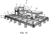
- connection pins 31 of the connection system 30 of the service vehicle 20 are connected to the connection interface CI and the connector pins 31 are in their upper and locked position. It can also be seen in Fig. 15 that the unit 60 is lifted by the service vehicle 20, i.e. the unit 60 is not in contact with the track system 108.
- the distance between the respective downwardly protruding supporting elements 64 are adapted to the track system 108.
- the downwardly protruding supporting elements 64 will come into contact with the track system 108 and the service vehicle 20 can disconnect from the unit 60.
- the service vehicle 20 can re-connect to the unit 60 by moving towards the unit 60 with its connector pins 31 in their lower position and then elevate the connector pins 31 when they have been inserted into the keyhole of the connection interface again.
- the additional support unit 60 comprises a further connection system 70 for connection to a container handling vehicle 240,250.
- the connection system 70 comprises a wheel actuator 72 and a push body 74, 75 for contact with the container handling vehicle 240,250 when it is pushed by the service vehicle 20.
- the further connection system 70 comprises a pull body 76 for contact with the container handling vehicle 240,250 when pulled by the service vehicle 20.
- the pull body 76 may be hook or other type of connection interface for connection to an interface of the container handling vehicle 240,250.
- connection system 30 of the service vehicle 20 in this example may have a third position.
- the connection system 30 In the first position, as described above, the connection system 30 has lowered the unit and the unit is in contact with the track system 108.
- the service vehicle may move the connector pin 31 into or out from the keyhole KH of the connection interface CI.
- the connection system 30 In the second position, the connection system 30 has lifted the unit and the unit is no longer in contact with the track system 108.
- the pull body 76 is not sufficiently elevated to be moved over the vehicle 240,250.
- the connector pins 31 and hence the unit 60 is elevated to a third position above the second position.
- the length of the elongated bar elements 62 is adapted to the length between the rails 111. Hence, when moving along tracks 111, four tracks 11 are in contact with the wheels of the service vehicle 20 and the wheels of the vehicle 301, while when moving along tracks 110, the same two tracks are used both by the service vehicle 20 and the vehicle 240,250.
- the additional support unit is here a counterweight unit 60d for balancing the service vehicle 20.
- the unit 60d has a connection interface CI (not shown) which in Fig. 18A and 18B is connected to the connection system 30 provided on the second side 3B of the vehicle body 3.
- the counterweight unit 60d is lifted by the service vehicle 20.
- the purpose of the counterweight unit 60d is to enable the service vehicle 20 to lift and transport a failed container handling vehicle 240,250 of the type shown in Fig. 18A and 18B .
- the container handling vehicle 240,250 is similar to prior art vehicles, with one modification:
- the container handling vehicle 240,250 comprises a connection interface CI.
- the connection interface CI is provided as two openings in the vehicle body 252, one opening for each of the connector pins 31 of the connection system 30 on the second side 3B of the vehicle body 3 of the service vehicle 20.
- Fig. 18C it is shown that the connector pins 31 of the connection system 30 moved into the openings of the connection interface CI of the vehicle 240,250.
- connection system 30 is in the second (or third) position, lifting the vehicle 240,250 up from the grid. Due to the counterweight unit 60d, the service vehicle 20 will not tilt when lifting the vehicle 240,250.
- the connector pin 31 including the pin head 31a was rotationally symmetrical around its longitudinal axis.
- FIG. 20A-D It is now referred to Fig. 20A-D , where some examples of alternative embodiments are shown.
- the connector pin 31 is not rotationally symmetrical, as only the upper part of the pin head 31a is protruding upwardly in a direction perpendicular to the longitudinal axis X31.
- the keyhole KH of the connection interface is oval-shaped.
- the pin head 31a is a rectangle protruding up from the connector pin 31.
- the keyhole KH of the connection interface is circular.
- the pin head 31a corresponds to the one shown in Fig. 20B .
- the distal end of the head is rounded, to ease insertion into the keyhole KH.
- the keyhole KH of the connection interface is semicircular.
- the pin head 31a is formed by providing a notch in the connector pin 31 itself, thereby separating the connector pin 31 into two separate sections, a distal section forming the pin head 31a and a proximal section 31b.
- the keyhole KH of the connection interface is rectangular.
- the operation of the actuator 34 may be dependent on, or independent of, the operation of the drive system 40.
- the vertical distance between the slot 24 and the track system will be the same when the service vehicle is moving along tracks 110 and when the service vehicle is moving along tracks 110.
- the operation of the actuator 34 can be independent from the drive system 40.
- the actuator may be operated to change the height of the connector pins based on the travel direction.
Landscapes
- Engineering & Computer Science (AREA)
- Mechanical Engineering (AREA)
- Physics & Mathematics (AREA)
- General Physics & Mathematics (AREA)
- Computer Networks & Wireless Communication (AREA)
- Signal Processing (AREA)
- Automation & Control Theory (AREA)
- Mathematical Physics (AREA)
- Quality & Reliability (AREA)
- Environmental & Geological Engineering (AREA)
- General Engineering & Computer Science (AREA)
- Robotics (AREA)
- Business, Economics & Management (AREA)
- Health & Medical Sciences (AREA)
- Emergency Management (AREA)
- Manufacturing & Machinery (AREA)
- Public Health (AREA)
- Aviation & Aerospace Engineering (AREA)
- Radar, Positioning & Navigation (AREA)
- Remote Sensing (AREA)
- Warehouses Or Storage Devices (AREA)
- Control Of Position, Course, Altitude, Or Attitude Of Moving Bodies (AREA)
- Forklifts And Lifting Vehicles (AREA)
Abstract
- a plurality of remotely operated container handling vehicles (230,330,240,340,250,350) configured to move laterally on the rail system (108,308); and
- a main control system (109) using a first communication system for communicating with the plurality of remotely operated container handling vehicles (230,330,240,340,250,350), wherein the main control system (109) monitors and controls the movement of the plurality of container handling vehicles (230,330,240,340,250,350) via the first communication system;
- at least one service vehicle movable on the rail system (108,308), wherein the at least one service vehicle is configured to bring a malfunctioning remotely operated container handling vehicle to a service area (160) outside of the rail system where the remotely operated container handling vehicles (230,330,240,340,250,350) operate;
wherein the system further comprises:
- a secondary control system using a second communication system, wherein the second communication system is independent of the main communication system, wherein the secondary control system for communicating with the at least one service vehicle on the rail system such as to monitor and control the movement of the at least one service vehicle.
Description
- System, method and main control system for handling malfunctioning vehicles in an automated storage and retrieval system comprising a rail system.
- The present invention relates to a method for handling malfunctioning vehicles on a rail system constituting part of a storage and retrieval system configured to store a plurality of stacks of storage containers, a storage and retrieval system and a control system carrying out the method, and a main control system for an automated storage and retrieval system.
-
Fig. 1A discloses a typical prior art automated storage andretrieval system 1 with aframework structure 100. - The
framework structure 100 comprises a plurality ofupright members 102 and optionally a plurality ofhorizontal members 103 supporting theupright members 102. Themembers - The
framework structure 100 defines astorage grid 104 comprisingstorage columns 105 arranged in rows, in whichstorage columns 105 storage containers 106 (also known as bins) are stacked one on top of another to formstacks 107. - Each
storage container 106 may typically hold a plurality of product items (not shown), and the product items within astorage container 106 may be identical or may be of different product types depending on the application. - The
storage grid 104 guards against horizontal movement of thestorage containers 106 in thestacks 107, and guides vertical movement of thestorage containers 106, but does normally not otherwise support thestorage containers 106 when stacked. - The automated storage and
retrieval system 1 comprises arail system 108 arranged in a grid pattern across the top of thestorage 104, on whichrail system 108 a plurality of container handling vehicles 250 (as exemplified inFig. 1C ) are operated to raisestorage containers 106 from, andlower storage containers 106 into, thestorage columns 105, and also to transport thestorage containers 106 above thestorage columns 105. The horizontal extent of one of thegrid cells 122 constituting the grid pattern is inFigs. 1A marked by thick lines. - The
rail system 108 comprises a first set ofparallel rails 110 arranged to guide movement of thecontainer handling vehicles 250 in a first direction X across the top of theframe structure 100, and a second set ofparallel rails 111 arranged perpendicular to the first set ofrails 110 to guide movement of thecontainer handling vehicles 250 in a second direction Y which is perpendicular to the first direction X. In this way, therail system 108 defines grid columns above which thecontainer handling vehicles 250 can move laterally above thestorage columns 105, i.e. in a plane which is parallel to the horizontal X-Y plane. - The
rail system 108 may be a single rail system or a double rail system as is shown inFig. 1B . The latter rail configuration allows acontainer handling vehicle 250 having a footprint generally corresponding to the lateral area defined by agrid cell 122 to travel along a row of grid columns even if anothercontainer handling vehicle 250 is positioned above a grid cell neighboring that row. Both the single and double rail system, or a combination comprising a single and double rail arrangement in asingle rail system 108, forms a grid pattern in the horizontal plane P comprising a plurality of rectangular and uniform grid locations orgrid cells 122, where eachgrid cell 122 comprises agrid opening 115 being delimited by a pair of neighboringrails rails 110 and a pair of neighboringrails rails 111. - Consequently,
rails rails - As shown in
Fig. 1B , each grid cell 122 (indicated by a dashed box) has a width Wc which is typically within the interval of 30 to 150 cm, and a length Lc which is typically within the interval of 50 to 200 cm. Eachgrid opening 115 has a width Wo and a length Lo which is typically 2 to 10 cm less than the width Wc and the length Lc of thegrid cell 122. -
Fig. 1C discloses a prior artcontainer handling vehicle 250 operating thesystem 1 disclosed inFigs. 1A . Each prior artcontainer handling vehicle 250 comprises avehicle body 252 and awheel arrangement 251 of eight wheels, where a first set of four wheels enable the lateral movement of thecontainer handling vehicles 250 in the X direction and a second set of the remaining four wheels enable the lateral movement in the Y direction. One or both sets of wheels in thewheel arrangement 251 can be lifted and lowered, so that the first set of wheels and/or the second set of wheels can be engaged with the respective set ofrails - Each prior art
container handling vehicle 250 also comprises a lifting device (not shown) for vertical transportation ofstorage containers 106, e.g. raising astorage container 106 from, and lowering astorage container 106 into, astorage column 105. The lifting device may comprise one or more gripping / engaging devices which are adapted to engage astorage container 106, and which gripping / engaging devices can be lowered from thevehicle 250 so that the position of the gripping / engaging devices with respect to the vehicle can be adjusted in a third direction Z which is orthogonal the first direction X and the second direction Y. - Conventionally, and also for the purpose of this application, Z=1 identifies the uppermost layer of the
grid 104, i.e. the layer immediately below therail system 108, Z=2 the second layer below therail system 108, Z=3 the third layer etc. In the exemplaryprior art grid 104 disclosed inFig. 1A , Z=8 identifies the lowermost, bottom layer of thegrid 104. Consequently, as an example, and using the Cartesian coordinate system X, Y, Z indicated inFig. 1A , the storage container identified as 106' inFig. 1A can be said to occupy grid location or cell X=10, Y=2, Z=3. Thecontainer handling vehicles 250 can be said to travel in layer Z=0 and each grid column can be identified by its X and Y coordinates. - Each
container handling vehicle 250 comprises a storage compartment or space (not shown) for receiving and stowing astorage container 106 when transporting thestorage container 106 across therail system 108. The storage space may comprise a cavity arranged centrally within thevehicle body 252, e.g. as is described inWO2014/090684A1 , the contents of which are incorporated herein by reference. - The container handling
vehicles 250 may have a footprint, i.e. an extent in the X and Y directions, which is generally equal to the lateral extent of agrid cell 122, i.e. the extent of agrid cell 122 in the X and Y directions, e.g. as is described inWO2015/193278A1 , the contents of which are incorporated herein by reference. The term "lateral" used herein may mean "horizontal". - Alternatively, the container handling vehicles may have a footprint which is larger than the lateral extent of (lateral area defined by) a
grid column 105, e.g. as is disclosed inWO2014/090684A1 . - In the X and Y directions, neighboring grid cells are arranged in contact with each other such that there is no space there-between.
- In a
storage grid 104, a majority of the grid columns arestorage columns 105,i.e. grid columns 105 wherestorage containers 106 are stored instacks 107. However, agrid 104 normally has at least one grid column which is used not for storingstorage containers 106, but which comprises a location where thecontainer handling vehicles 250 can drop off and/or pick upstorage containers 106 so that they can be transported to a second location (not shown) where thestorage containers 106 can be accessed from outside of thegrid 104 or transferred out of or into thegrid 104. Within the art, such a location is normally referred to as a "port" and the grid column in which the port is located may be referred to as a "delivery column" 119,120. The drop-off and pick-up ports of the container handling vehicles are referred to as the "upper ports of a delivery column" 119,120. While the opposite end of the delivery column is referred to as the "lower ports of a delivery column". - The
storage grid 104 inFig. 1A comprises twodelivery columns first delivery column 119 may for example comprise a dedicated drop-off port where thecontainer handling vehicles 250 can drop offstorage containers 106 to be transported through thedelivery column 119 and further to an access or a transfer station, and thesecond delivery column 120 may comprise a dedicated pick-up port where thecontainer handling vehicles 250 can pick upstorage containers 106 that have been transported through thedelivery column 120 from an access or a transfer station. Each of the ports of the first and second delivery column may comprise a port suitable for both pick up and drop of storage containers. - The second location may typically be a picking or a stocking station where product items are removed from or positioned into the
storage containers 106. In a picking or a stocking station, thestorage containers 106 are normally never removed from the automated storage andretrieval system 1 but are returned into thestorage grid 104 once accessed. For transfer of storage containers out or into thestorage grid 104, there are also lower ports provided in a delivery column, such lower ports are e.g. for transferringstorage containers 106 to another storage facility (e.g. to another storage grid), directly to a transport vehicle (e.g. a train or a lorry), or to a production facility. - A conveyor system may also be arranged to transfer storage containers between different storage grids, e.g. as is described in
WO2014/075937A1 , the contents of which are incorporated herein by reference. - When a
storage container 106 stored in thestorage grid 104 disclosed inFig. 1A is to be accessed, one of thecontainer handling vehicles 250 is instructed to retrieve thetarget storage container 106 from its position in thegrid 104 and transport it to or through thetransfer column 119. This operation involves moving thecontainer handling vehicle 250 to a grid location above thestorage column 105 in which thetarget storage container 106 is positioned, retrieving thestorage container 106 from thestorage column 105 using the container handling vehicle's lifting device (not shown), and transporting thestorage container 106 to thetransfer column 119. If thetarget storage container 106 is located deep within astack 107, i.e. with one or a plurality of other storage containers positioned above thetarget storage container 106, the operation also involves temporarily moving the above-positioned storage containers prior to lifting thetarget storage container 106 from thestorage column 105. This step, which is sometimes referred to as "digging" within the art, may be performed with the samecontainer handling vehicle 250 that is subsequently used for transporting thetarget storage container 106 to the transfer column, or with one or a plurality of other cooperatingcontainer handling vehicles 250. Alternatively, or in addition, the automated storage andretrieval system 1 may have container handling vehicles specifically dedicated to the task of temporarily removingstorage containers 106 from astorage column 105. Once thetarget storage container 106 has been removed from thestorage column 105, the temporarily removed storage containers can be repositioned into theoriginal storage column 105. However, the removed storage containers may alternatively be relocated toother storage columns 105. - When a
storage container 106 is to be stored in thegrid 104, one of thecontainer handling vehicles 250 is instructed to pick up thestorage container 106 from thetransfer column 120 and to transport it to a grid location above thestorage column 105 where it is to be stored. After any storage containers positioned at or above the target position within thestorage column stack 107 have been removed, thecontainer handling vehicle 250 positions thestorage container 106 at the desired position. The removed storage containers may then be lowered back into thestorage column 105 or relocated toother storage columns 105. - For monitoring and controlling the automated storage and
retrieval system 1 so that a desiredstorage container 106 can be delivered to the desired location at the desired time without thecontainer handling vehicles 250 colliding with each other, the automated storage andretrieval system 1 comprises acontrol system 109, which typically is computerized and comprises a database for monitoring and controlling e.g. the location of therespective storage containers 106 within thestorage grid 104, the content of eachstorage container 106 and the movement of thecontainer handling vehicles 250. - A problem associated with known automated storage and
retrieval systems 1 is that it is challenging for personnel to access therail system 108 for carrying out inspection, or to carry out maintenance of or to remove malfunctioningcontainer handling vehicles 250. - Another important problem with maintenance or removal of malfunctioning
vehicles 250 is that a complete shutdown of thesystem 1 is needed for the personnel to access with low or zero risk of injury. In particular forlarge systems 1, forexample systems 1 with in excess of 500 vehicles in operation simultaneously, a complete shutdown is highly undesired due to significant cost for the operator. - Prior art includes
WO2015/140216 A1 disclosing a service robot which operates under the same control system as the container robots.WO2015/140216A1 discloses a service vehicle for cleaning the grid and for inspection of the grid. The service vehicle is arranged with a releasable latching mechanism for docking with a malfunctioning container handling vehicle. In addition, the publication suggests that the service vehicle may be arranged with a seat for carrying a user to inspect and carry out maintenance. This personnel carrying version of the service vehicle may be manually operated by the user, or alternatively remotely controlled by the control system. - For these operations to happen safely it is necessary to stop all container handling vehicles on the grid before the user is allowed access. The higher the number of robotic load handlers in use and the larger the grid, the higher the likelihood of faults occurring and an increased consequence of each fault, due to the number of units which have to be stopped.
- It is an objective of the invention to provide a malfunctioning container handling vehicle without shutting down the system.
- The present invention is set forth and characterized in the independent claims, while the dependent claims describe other characteristics of the invention.
- It is described an automated storage and retrieval system comprising a rail system with perpendicular tracks in X and Y direction, wherein the storage and retrieval system comprises:
- a plurality of remotely operated container handling vehicles configured to move laterally on the rail system; and
- a main control system using a first communication system for communicating with the plurality of remotely operated container handling vehicles; wherein the main control system monitors and controls the movement of the plurality of container handling vehicles via the first communication system;
- at least one service vehicle movable on the rail system, wherein the at least one service vehicle is configured to bring a malfunctioning remotely operated container handling vehicle to a service area outside of the rail system where the remotely operated container handling vehicles operate;
- a second control system using a second communication system, wherein the second communication system is independent of the main communication system, and wherein the secondary control system is communicating with the at least one service vehicle on the rail system such as to monitor and control the movement of the at least one service vehicle.
- The main control system may thus monitor and control the movement of the plurality of container handling vehicles via the first communication system.
- The second control system may thus monitor and control the movement of the at least one service vehicle via the second communication system.
- The term independent, i.e. that the second communication system is independent of the first communication system, shall be understood as the two communication systems which cannot interfere with one another. However, the main control system and secondary control system may operate under a same master controller.
- Both the first communication system and the second communication system preferably operate using wireless communication.
- In an aspect, the main control system may be configured to perform, by wireless data communication, at least the following steps:
- A. determining an anomaly in an operational condition of a vehicle on the rail system,
- B. registering the vehicle with the anomalous operational condition as a malfunctioning vehicle,
- C. registering a position of the malfunctioning vehicle relative to the supporting rail system.
- A malfunctioning vehicle may be a vehicle which is partly malfunctioning or a vehicle which is not functioning at all. A vehicle not functioning at all may e.g. have completely stopped and/or communication with the first communication system may have been interrupted for some reason.
- The main control system is further configured to perform:
D. setting up a two-dimensional exclusion zone extending from the malfunctioning vehicle to a position of the service vehicle. - The exclusion zone may be set up along the shortest route to the malfunction vehicle. Alternatively, the exclusion zone may not be the shortest route but selected based on other parameters. For example, the exclusion zone may be along a perimeter of the rail system, e.g., to maintain an as large as possible and an as effective as possible working area for the vehicles to operate in. In other words, the exclusion zone might take up more overall area of the working area but that might still result in more efficient operation.
- The main control system may further be configured to perform:
E. updating a movement pattern of the plurality of remotely operated vehicles by instructing any remotely operated vehicles positioned within the two-dimensional exclusion zone to move outside of the two-dimensional exclusion zone and avoiding entry of any of the remaining remotely operated vehicles into the two-dimensional exclusion zone. - Therefore, the remotely operated vehicles that are currently in the exclusion zone when the main control system updates the movement pattern and sets up an exclusion zone, are routed to a position outside the exclusion zone. Such re-routing of the remotely operated vehicles ensure that remotely operated vehicles do not represent obstacles to the service vehicle. It also allows these remotely operated vehicles to perform container handling operations whilst the exclusion zone is in effect. In other words, any remotely operated vehicle currently in grid cells that are to form part of an exclusion zone are re-rerouted to grid cells outside of the planned exclusion zone. Therefore, the remotely operated vehicles will need to be identified and moved out of the way before the occupied cells forms part of a planned exclusion zone.
- When the main control system has performed the above steps, the secondary control system may be configured to perform, by wireless data communication, at least the following step:
F. operating the at least one service vehicle to move from an initial position to a position next to the malfunctioning vehicle along the exclusion zone. - The first communication system and the second communication system may be the same communication system or different communication systems. Such communication system may include WiFi, light (e.g. Lifi) etc.
- The first communication system and the second communication system may operate with different frequencies.
- The first communication system and the second communication system may have different coding and de-coding processes.
- For example, the first communication system is wireless fidelity (WiFi) and the second communication system is light fidelity (LiFi).
- The second communication system maybe automatically or manually operated. In the event of manual operation, an operator may remotely control the service vehicle along the exclusion zone using a remote control or similar.
- The service vehicle may comprise wheels which are guided for movement along the rails in X and Y directions.
- The service vehicle may comprise caterpillar tracks for movement over a top surface of the rail system independent of the X and Y directions of the rail system.
- An initial position of the service vehicle may be in a service area outside of the rail system where the remotely operated vehicles operate.
- If the service vehicle comprises wheels, the service area preferably comprises rails connected to the rail system.
- In one embodiment, the rail system is at a top level of a storage grid.
- In one embodiment, the rail system is a delivery rail system.
- It is further described a method for handling malfunctioning vehicles on a rail system wherein the storage and retrieval system comprises:
- a plurality of remotely operated container handling vehicles configured to move laterally on the rail system; and
- a main control system using a first communication system for communicating with the plurality of vehicles wirelessly, wherein the main control system monitors and controls the movement of the plurality of container handling vehicles via the first communication system;
- at least one service vehicle positioned at an initial position, wherein the service vehicle is movable on the rail system, and wherein the at least one service vehicle is configured to bring a malfunctioning remotely operated container handling vehicle to a service area outside of the rail system where the remotely operated container handling vehicles operate;
- a secondary control system, using a second communication system which is independent of the main control system for communicating with the at least one service vehicle on the rail system wirelessly, and wherein the secondary control system monitors and controls the movement of the at least one service vehicle;
- A. determining an anomaly in an operational condition of a vehicle on the rail system,
- B. registering the vehicle with the anomalous operational condition as a malfunctioning vehicle,
- C. registering a position of the malfunctioning vehicle relative to the supporting rail system.
- The method may further comprise utilizing the main control system to perform:
D. setting up a two-dimensional exclusion zone extending from the malfunctioning vehicle to the position of the service vehicle. - The method may further comprise utilizing the main control system to perform:
E. updating movement pattern of the plurality of remotely operated vehicles outside the two-dimensional exclusion zone such that entrance into the two-dimensional exclusion zone is avoided. - The method may further comprise, when the main control system has performed the above steps, the secondary control system performs by wireless data communication at least the following step:
F. operating the at least one service vehicle to move from its initial position to the position where the malfunctioning vehicle is halted along the exclusion zone. - It is further described a main control system for an automated storage and retrieval system, the automated storage and retrieval system comprising:
- a rail system with horizontal tracks extending in perpendicular X and Y directions;
- a plurality of remotely operated container handling vehicles configured to operate on the rail system;
- a service vehicle; and
- a secondary control system for the service vehicle wherein the secondary control system is communicating with the at least one service vehicle on the rail system such as to monitor and control the movement of the at least one service vehicle , and wherein the at least one service vehicle is configured to bring a malfunctioning remotely operated container handling vehicle to a service area outside of the rail system where the remotely operated container handling vehicles operate,
- reconfigure the working zone to divide off an exclusion zone, the exclusion zone defining an area of the rail system containing the malfunctioning remotely operated vehicle and providing a path for the service vehicle to reach the malfunctioning remotely operated vehicle;
- reroute other remotely operated vehicles operating in the exclusion zone and in the reconfigured working zone so that they avoid the area of the rail system defined by the exclusion zone; and
- hand over control of the area of the rail system in the exclusion zone to the secondary control system.
- In one aspect, the automated storage and retrieval system described above comprises the main control system described in the latter.
- The main control system may be configured, once the service vehicle has moved out of the exclusion zone of the rail system, to:
- take back control of the area of the rail system within the exclusion zone from the secondary control system;
- reconfigure the working zone to include the area of the rail system that was previously in the exclusion zone; and
- reroute remotely operated vehicles to take account of the increased working zone with the area of the rail system previously in the exclusion zone included as part of the working zone.
- The following drawings are appended to facilitate the understanding of the invention:
-
Fig. 1 is a perspective view of a prior art automated storage and retrieval system, whereFig. 1 A shows the complete system,Fig. 1 B shows a top view of a prior art double rail grid andFig. 1 C shows an example of a system operable prior art container handling vehicle; -
Fig. 2 is a schematic top view of an automated storage and retrieval system according to wherein the system is divided into three subsystems by physical barriers;Figs. 3A and 3B are perspective views of an exemplary automated storage and retrieval system according to the invention, whereFig. 3A shows a part of the system having a delivery rail system with container delivery vehicles operating below the rail system of container handling vehicles andFig. 3B shows an example of a container delivery vehicle having a storage container stored within; -
Fig. 4 shows a flow chart of operation when an anomaly is registered in an operational condition of a vehicle; -
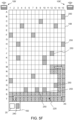
Figs. 5A-5F show an example of operational sequence when it is registered that a vehicle is malfunctioning, i.e. an anomaly in the operational condition of a vehicle, and how an exclusion zone on a rail system may be set up, and further the relationship between a first communication system operating the vehicles and a second communication system operating the service vehicle in order for the service vehicle to move from a service area along the exclusion zone to pick up and transport the malfunction vehicle back to the service area; -
Figs. 6A and 6B are perspective views of ride-on service vehicles suitable for operating on a rail system of an automated storage and retrieval system, whereFig. 6A shows a service vehicle having two set of wheels configured to follow the rails in X and Y directions andFig. 6B shows a service vehicle having caterpillar tracks configured to drive on top of the rail system; -
Figs. 7 A-C are perspective side views of a service vehicle being configured to be operated remotely; -
Figs. 8 A - C are perspective side views of the service vehicle ofFig. 7 , whereFig. 8 A shows the service vehicle approaching a container handling vehicle to be serviced,Fig. 8 B shows the service vehicle partly surrounding the container handling vehicle andFig. 8 C shows the service vehicle gripping the container handling vehicle by use of its handling mechanism; -
Figs. 9 A andB are perspective side views of the service vehicle ofFigs. 7 and8 , whereFig. 9 A andFig. 9 B show the service vehicle in an operating position where the container handling vehicle is contacting the rail system and a transport position where the container handling vehicle is raised above the rail system, respectively; -
Fig. 10 illustrates a perspective view from below of an exemplary service vehicle; -
Fig. 11 illustrates a perspective side view of the service vehicle inFig. 10 ; -
Fig. 12 illustrates another perspective view from below of the service vehicle shown inFig. 10 ; -
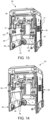
Fig. 13 . illustrates the inside of the service vehicle ofFig. 10 with the actuators in the lower position; -
Fig. 14 illustrates the inside of the service vehicle ofFig. 10 with the actuators on one side in the upper position; -
Fig. 15 illustrates a perspective view of an exemplary service vehicle using an adaptor to connect to a first type of container handling vehicle; -
Fig. 16 illustrates a perspective view of the connection interface of the first type of container handling vehicle before being connected to the adapter; -
Fig. 17 illustrates the service vehicle and adapter ofFig. 16 being connected to the container handling vehicle; -
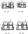
Fig. 18A illustrates a perspective side view of an exemplary service vehicle with to a counterbalance connected to it and adjacent to a second type of container handling vehicle; -
Fig. 18B illustrates another perspective view of the service vehicle ofFig. 18A and the second type of container handling vehicle; -
Fig. 18C illustrates the service vehicle ofFig. 18A being connected to both the weight unit and the second type of container handling vehicle; -
Fig. 18D illustrates how that the service vehicle ofFig. 18A is able to lift the second type of container handling vehicle up from the rails; -
Fig. 19A illustrates a cross sectional view of an exemplary connection system;Fig. 19B illustrates a front view of the connection interface ofFig. 19A ; -
Fig. 19C illustrates a cross sectional view along line A-A inFig. 19B ; -
Fig. 19D illustrates a cross sectional view of some parts of the connection system being in contact with the connection interface; and -
Fig. 20A-D illustrate alternative embodiments of the connection system. - In the drawings, the same reference numerals have been used to indicate like parts, elements or features unless otherwise explicitly stated or implicitly understood from the context.
- In the following, embodiments of the invention will be discussed in more detail with reference to the appended drawings. It should be understood, however, that the drawings are not intended to limit the invention to the subject-matter depicted in the drawings.
- With reference to
Fig. 1 the automated storage andretrieval system 1 comprises aframework structure 100 which includes astorage grid 104 of in total 1144 grid cells, where the width and length of thegrid 104 corresponds to the width and length of 143 grid columns. The top layer of theframework structure 100 is arail system 108 onto which a plurality ofcontainer handling vehicles 250 are operated. - The
framework structure 100 may be constructed in accordance with the priorart framework structure 100 described above, i.e. a plurality ofupright members 102 and a plurality ofhorizontal members 103 which are supported by theupright members 102. - The
rail system 108 includes parallel rails 110,111 along the X direction and the Y direction, respectively, arranged across the top ofstorage columns 105. The horizontal area of agrid cell 122 delimiting the opening into thestorage column 105 may be defined by the distance betweenadjacent rails - In
Fig. 1 , asingle grid cell 122 is marked on therail system 108 by thick lines inFig. 1A and shown in a top view inFig. 1B . - The
rail system 108 allows thecontainer handling vehicles 250 to move horizontally between different grid locations, where each grid location is associated with agrid cell 122. - In
Fig. 1A thestorage grid 104 is shown with a height of eight cells. It is understood, however, that thestorage grid 104 can in principle be of any size. In particular, It is understood thatstorage grid 104 can be considerably wider and/or longer than disclosed inFig. 1 . For example, thegrid 104 may have a horizontal extension of more than700x700 grid cells 122. Also, thegrid 104 can be considerably deeper than disclosed inFigs. 1 and2 . For example, thestorage grid 104 may have a depth corresponding to a stable 107 of tenstorage containers 106 or more. - All
container handling vehicles 250 may be controlled by a main control system with a first communication system as indicated with reference numeral 109'. - The
container handling vehicles 250 may be of any type known in the art, e.g. any one of the automated container handling vehicles disclosed inWO2014/090684 A1 , inNO317366 WO2015/193278A1 . -
Fig. 2 shows a top view of an automated storage andretrieval system 1. Thesystem 1 comprises threeframework structures 100a-c, each having astorage grid 104 withstacks 107 ofstorage containers 106, arail system 108a-c arranged on top of thestorage grid 104 and aservice area 160a-c. Theframework structures 100a-c are separated by twovehicle blocking barriers 125, e.g., walls, arranged between therail systems 108a-c. Each of thebarriers 125 includes one ormore passages 130a,b in whichcontainer handling vehicles 250 may drive through during normal operation. - In
Fig. 2 a particular situation is depicted where acontainer handling vehicle 240 has been labeled malfunctional and brought to a halt at a location on themid rail system 108b. - The
service areas 160a-c may be adjacent to a mezzanine outside the boundary of therail systems 108, for supporting theservice vehicle 20 while it is inactive. - In
Fig. 2 , aservice area 160a-c and aservice vehicle 20 is depicted for each of therail systems 108a-c. However, other configurations may be envisaged such as an arrangement of only onemid service area 160b, allowing entrance of aservice vehicle 20 into themid rail system 108b. In case a malfunctioningvehicle 240 is brought to a halt in theleft rail system 108a or theright rail system 108c, theservice vehicle 20 may, with such a configuration, travel through therespective passage 130a,b and into the affectedrail system 108a,c. - A different automated storage and
retrieval system 1 is shown in part inFig. 3A . Theupright members 102 constitute part of aframework structure 100 onto which atransport rail system 108 with a plurality ofcontainer handling vehicles 250 are operating. - Below this
transport rail system 108, near the floor level, anotherframework structure 300 is shown which partly extends below some of thestorage columns 105 of theframework structure 100. As for theother framework structure 100, a plurality of vehicles 330,340,350 may operate on arail system 308 comprising a first set of parallel rails 310 directed in a first direction X and a second set of parallel rails 311 directed in a second direction Y perpendicular to the first direction X, thereby forming a grid pattern in the horizontal plane PL comprising a plurality of rectangular and uniform grid locations orgrid cells 322. Each grid cell of thislower rail system 308 comprises agrid opening 315 being delimited by a pair of neighboringrails rails - The part of the
lower rail system 308 that extends below thestorage columns 105 are aligned such that itsgrid cells 322 are in the horizontal plane PL coincident with thegrid cells 122 of theupper rail system 108 in the horizontal plane P. - Hence, with this particular alignment of the two rail systems 108,308, a
storage container 106 being lowered down into astorage column 105 by acontainer handling vehicle 250 can be received by adelivery vehicle 350 configured to run on therail system 308 and to receivestorage containers 106 down from thestorage column 105. In other words, thedelivery vehicle 350 is configured to receivestorage containers 106 from above, preferably directly from thecontainer handling vehicle 250. -
Fig. 3B shows an example of such avehicle 350 comprising awheel assembly 351 similar to thewheel assembly 251 described for the prior artcontainer handling vehicle 250 and astorage container support 352 for receiving and supporting astorage container 106 delivered by an abovecontainer handling vehicle 250. - After having received a
storage container 106, thedelivery vehicle 350 may drive to an access station adjacent to the rail system 308 (not shown) for delivery of thestorage container 106 for further handling and shipping. - Hereinafter, the upper and lower rail systems 108,308 are called the
transport rail system 108 and thedelivery rail system 308. Likewise, the vehicle shown inFig. 3B is called acontainer delivery vehicle 350. -
Fig. 4 shows aflow chart 400 of operation when an anomaly is registered in an operational condition of a vehicle. The flow chart includes the following steps: - 401: Registering an anomaly in an operational condition of a vehicle.
- 402: Labelling the vehicle as a malfunctioning vehicle 240,340.
- 403: Requesting the malfunctioning vehicle 240,340 to stop or remain still.
- 404: Registering the stop position XS, YS of the malfunctioning vehicle 240,340.
- 405: Setting up an exclusion zone 225,325 on the rail system 108,308 using the main control system 109' from the stop position of the malfunctioning vehicle 240,340 and to the position of a
service vehicle 20. - 406: Are there operative vehicles within the shutdown zone 225,325?
- If "YES" in
step 406, a step of: - 407: Rerouting all of the operating vehicles 250,350 out of the shutdown zone 225,325. If "NO" in
step 406, a step of: - 408: Routing a
service vehicle 20 using asecondary control system 109" from an initial position along the exclusion zone 225,325 for handling of the malfunctioning vehicle 240,340. - 409: Bringing the malfunctioning vehicle 240,340 using the
service vehicle 20 to aservice area 160. - 410: Utilizing the main control system 109' to re-open the
exclusion zone 225 allowing theoperative vehicles 250 to enter theexclusion zone 225. -
Figs. 5A-5F show an example of operational sequence when it is registered that a vehicle is malfunctioning, i.e. an anomaly in the operational condition of a vehicle, and how an exclusion zone on a rail system may be set up, and further the relationship between a first communication system operating the vehicles and a second communication system operating the service vehicle in order for the service vehicle to move from a service area along the exclusion zone to pick up and transport the malfunction vehicle back to the service area. - In
Fig. 5A the main control system 109' registers that the container handling vehicle 240 (denoted X) in cell M12 is malfunctioning. - In
Fig. 5B thecontainer handling vehicle 250 in cell T8 has moved to cell R8 under instructions from the main control system 109', as indicated by the back end point and front end point of arrow A1. In addition, thecontainer handling vehicle 250 in cell Q14 has moved to cell Q13 under instructions from the main control system 109', as indicated by the back end point and front end point of arrow A2. - In
Fig. 5C , an exclusion zone 225 (indicated by dashed area) has been created by the main control system 109' from theservice area 160 to the malfunctioning container handling vehicle (X,240). The disclosedexclusion zone 225 has two cells width and extends all the way through the S and T rows, further to M14 and M15 and to M12 and N12 creating a continuous path for theservice vehicle 20. - The
exclusion zone 225 has been created at the boundary of therail system 108 in order to minimize the impact on the remainingcontainer handling vehicles 250 operating on therail system 108. However, it will be understood that theexclusion zone 225 can be created anywhere on therail system 108, whatever is most expedient in the specific situation and preferably along a path which minimizes the interruption of the other container handling jobs. - In
Fig. 5D aservice vehicle 20 has left its initial position in theservice area 160 under control of thesecondary control system 109" and occupies cells S5-S6-T5-T6, as indicated by arrow A3. - In
Fig. 5E theservice vehicle 20 has moved to the position of the malfunctioning container handling vehicle X,240 (next to cell M12) as indicated by arrow A4, and under control of the second communication system 109''. - In
Fig. 5F theservice vehicle 20 has brought the malfunctioningcontainer handling vehicle 240,X to theservice area 160 along theexclusion zone 225 under control of the secondary control system 109'', as indicated by arrow A5. - Once the malfunctioning
container handling vehicle 240,X is within theservice area 160, the main control system 109' may be used to re-classify theexclusion zone 225 allowing theoperative vehicles 250 to enter the previously existedexclusion zone 225. - It shall be noted that in the example of
Figs. 5A-5F it is shown acontainer handling vehicle 250 operating on anupper rail system 108, i.e. thetransport rail system 108, however the operation will be identical for a delivery vehicle 330,340,350 operating on alower rail system 308, i.e. a delivery rail system 308 (as illustrated inFigs. 3A and 3B ). -
Figs. 6A and 6B are perspective views of ride-on service vehicles suitable for operating on a rail system of an automated storage and retrieval system, whereFig. 6A shows a service vehicle having two set of wheels configured to follow the rails in X and Y directions andFig. 6B shows a service vehicle having caterpillar tracks configured to drive on top of the rail system. Anotherservice vehicle 20 suitable for the operations described above is shown inFig. 7A, Fig. 7B and Fig. 7C . - In
Fig. 6A theservice vehicle 20 comprises a lifting mechanism. In both examples ofFigs 6A and 6B theservice vehicles 20 comprises aseat 25 for the operator and asupport base 22 for support of malfunctioning vehicles 240,340 and driving means 23 to enable movement of theservice vehicle 20. Theservice vehicle 20 could of course comprise other configurations and the present invention is not limited to these two examples. - In
Fig. 6A the driving means 23 comprises two set of four wheels, where at least one of the sets may be raised and lowered. Hence, the driving means are similar to the driving means of the above describedcontainer handling vehicles 250 andcontainer delivery vehicles 350. The wheels follow the rails 110,310,111,311 of the transport and/or delivery rail system(s) 108,308. - In
Fig. 6B the driving means 23 of theservice vehicle 20 comprises caterpillar tracks configured to drive on top of the rails 110,310,111,311, thereby allowing movement in any direction in the horizontal planes P,PL of either thetransport rail system 108 or thedelivery rail system 308. -
Figs. 7-9 show aservice vehicle 20, in which all operations of thevehicle 20 are performed fully remotely, that is, without any need for a human operator to directly interact with a control system onboard thevehicle 20 during the service procedure. - The
service vehicle 20 ofFigs. 7-9 comprises two caterpillar tracks /rollers vehicle body 3. At least one of the two other vertical sides of thevertical body 3 is configured to receive at least one malfunctioning vehicle 240,340 to be serviced. -
Figures 7-9 shows a particular configuration where theservice vehicle 20 comprises two guidingpins 35 attached to each of the opposite vertical sides of thevehicle body 3 onto which thecaterpillar tracks vehicle body 3 displays a tapered end allowing the malfunctioning vehicle 240,340 to be guided correctly into thevehicle body 3. A remotely operatedregistration unit 9 in form of aforward camera 9a and arearward camera 9b is mounted on the top horizontal side of thevehicle body 3. - The
transfer device 8 comprises alifting mechanism 8c which includes one or more verticallinear actuators 8f. Each of theactuators 8f has one end connected to apivot support 8h that pivotally couples to thevehicle body 3 with a rotational axis parallel to theunderlying rail system 108 and the other end to alifting claw 8d. The liftingclaws 8d may be displaceable in a horizontal direction relative to thevehicle body 3 by use of horizontallinear actuators 8i, i.e. with a horizontal non-zero component. - The
service vehicle 20 is remotely operated by a remote control system via one or moreonboard transmitters 36. Alternatively, or in addition,similar transmitters 36 may be arranged on thevehicle body 3, within theregistration unit 9, on one or both of therollers - As for the above disclosed embodiments the caterpillar tracks /
rollers grid cells 122, preferably four or more. - The opening of the vertical containing handling vehicle receiving side of the
vehicle body 3, including any guidingpins 35, has a minimum width G being equal to, or larger than, the overall width of the malfunctioning vehicle(s) 240,340 to be serviced. - The procedure for picking up a malfunctioning vehicle 240,340 by the
service vehicle 20 may proceed in the following way: - (
Fig. 8A ) Theservice vehicle 20 approaches, along an exclusion zone, a position adjacent to the one or more malfunctioning vehicles 240,340 to be transported using signal communication between the main control system 109' and the one or more of the onboard transmitters / receivers. If needed, the orientation of theservice vehicle 20 is changed so that the vehicle receiving opening of theservice vehicle 20 is facing towards the malfunctioning vehicle(s) 240,340. - (
Fig. 8B and C ) Theservice vehicle 20 is remotely guided so that the malfunctioning vehicle(s) 240,340 enters through the receiving opening of thevehicle body 3, between the two caterpillar tracks /rollers 6 so that thetransfer device 8 is in an interacting position, i.e. with the plurality of liftingclaws 8d arranged on two opposite vertical sides of the or each malfunctioning vehicle 240,340. Alternatively, theservice vehicle 20 may be kept still, and the malfunctioning vehicle(s) 240,340 may be remotely guided into the vehicle receiving opening. The correct horizontal position of the malfunctioning vehicle 240,340 inside thevehicle body 3 can be further controlled by astopper 37 arranged on the vertical side opposite of the receiving opening. Such astopper 37 will also contribute to increase the structural stability of the malfunctioning vehicle 240,340 within thevehicle body 3. In the example shown infigures 7-9 this stopper is illustrated as a horizontal extending bar arranged to abut the malfunctioning vehicle 240,340 when the latter is fully inside thevehicle body 3 of theservice vehicle 20. - (
Fig. 9A ) When thetransfer device 8 is in the interacting position relative to the malfunctioning vehicle(s) 240,240, the liftingclaws 8d are displaced horizontally using the horizontallinear actuators 8i until the liftingclaws 8d make physical contact with the malfunctioning vehicle(s) 240,340. - (
Fig. 9B ) The vertical linear actuator(s) 8f is/are remotely operated, causing thevehicle body 3 to be lifted from therail system 108 due to the pivoting movement of the pivot support(s) 8h. As a result of the established physical contact between the liftingclaws 8d and the malfunctioning vehicle(s) 240,340, the latter is lifted from therail system 108, thereby setting theservice vehicle 20 in a transport position. - The
service vehicle 20 is moved to its predetermined position on therail system 108, or out of therail system 108, with the one or more malfunctioning vehicles 240,340. - In all embodiments, the
rollers toothed belt wheels chains 6d. However, it may be envisaged configuration where one or more of thetoothed wheels chain 6d. Instead oftoothed wheels rollers respective chains 6d. Further, therollers grid cell 122. - All the embodiments of the
service vehicle 20 inFigs 7-9 may be easily configured to be maneuvered on the rail system without the need for an onboard operator 50, for example by operations performed entirely by a remotely located human operator 50 or by a fully or partly automated control system or a combination thereof. - Embodiments may also be envisaged where the full operation of the
service vehicle 20 is partly due to the operation of an onboard operator and partly due to a remotely located human operator or alternatively a combination between the operation of an onboard operator and a fully or partly automated control system. - It is now referred to
Figs. 10-14 . Here, it is shown aservice vehicle 20 for performing support operations in the automated storage andretrieval system 1. - The
service vehicle 20 comprises avehicle body 3 with a central cavity 25 (Fig. 10 ). Adrive system 40 is provided in the lower part of theservice vehicle 20. Thedrive system 40 is configured to drive theservice vehicle 20 along thetrack system 108 of the automated storage andretrieval system 1. Thedrive system 40 comprises a motor, typically an electric motor, and a power source, typically a rechargeable battery. Thedrive system 40 further comprises a first set ofwheels 42 and a second set ofwheels 44, where theservice vehicle 20 is moving in a first direction (for example X-direction) when the first set ofwheels 42 are in contact with thetrack system service vehicle 20 is moving in a second direction (for example the Y-direction) when the second set ofwheels 44 are in contact with thetrack system 108. Thedrive system 40 also comprises an actuator for bringing the desired set of wheels in contact with the track system. Thedrive system 40 further comprises a control system for controlling the movement of theservice vehicle 20 within thesystem 1. It should be noted that thedrive system 40 of theservice vehicle 20 is considered to be known for a person skilled in the art. - The
service vehicle 20 further comprises aconnection system 30 provided on afirst side 3A of thevehicle body 3. Theconnection system 30 is connectable to, and disconnectable from, a connection interface CI, for example a connection interface CI of an additional support unit (seeFig. 15 ). Theconnection system 30 will be described in further in detail below. - First, it should be noted that the embodiment of the
service vehicle 20 shown in the drawings comprises oneconnection system 30 provided on afirst side 3A of thevehicle body 3 and anadditional connection system 30 provided on asecond side 3B, opposite of thefirst side 3A (seFig. 13 ). For many of the applications described herein, onesuch connection system 30 may be sufficient. It is also possible to provide theservice vehicle 20 with acorresponding connection system 30 on a third side and/or fourth side. - Now, the
connection system 30 will be described in detail with reference toFig. 13, 14 andFigs. 19A-19D . - In
Fig. 19A , it is shown that theexemplary connection system 30 comprises a connector member orpin 31 protruding through an aperture or slot 24 of thevehicle body 3. In the present embodiment, theconnector pin 31 has two sections, a first section having a head orpin head 31a and a second elongated section orshank 31b defined with a longitudinal axis X31. Theshank 31b is cylindrical in the present embodiment. - In the present embodiment, the
slot 24 is avertical slot 24, in which theconnector pin 31 can be moved vertically by means of anactuator 34. Theactuator 34 is an electriclinear actuator 34. - On the outside of the
vehicle body 3, afirst contact body 32 is provided. Thefirst contact body 32 can be connected to theconnector pin 31 or to thevehicle body 3 at a horizontal distance from thepin head 31a. In the present embodiment, thefirst contact body 32 is connected to and around theconnector pin 31. - In addition to the
first contact body 32, theconnection system 30 comprises asecond contact body 33 provided at a vertical distance from thefirst contact body 32. - A
rigid member 38 is provided on the inside of thevehicle body 21. Therigid member 38 is used to connect theactuator 34 to theconnector pin 31 and also to thefirst contact body 32. Moreover, thesecond contact body 33 is connected to therigid member 38 by means of aconnector 39. Hence, when theactuator 34 is moving vertically, also therigid member 38, theconnector pin 31 and the first andsecond contact bodies - In
Fig. 19A , theconnection system 30 is in its lower or unlocked position. - It is now referred to
Fig. 19B and 19C , in which the connection interface CI is shown to comprise a plate-shaped connection structure CS with a keyhole KH. In the present embodiment, the keyhole KH comprises a circular opening Kha into which thepin head 31a can be easily inserted and a narrower slot KHb above the circular opening Kha into which theshank 31b can be moved, but from which thepin head 31a cannot easily be retrieved. Hence, when theconnection system 30 is in the lower or unlocked position (and the connection interface CI is stationary), theconnector pin 31 may be moved into and out from the keyhole KH. - It is now referred to
Fig. 19D . Here it is shown that theconnector pin 31 has been moved into the keyhole KH and then moved upwardly by means of theactuator 34. This position is referred to as an upper or locked position. In this locked position, if the service vehicle is moved to the left inFig. 19D , the connection structure CS will be pulled together with theservice vehicle 20 as thepin head 31 is engaged with the rear side RS of the connection structure CS. By moving the connector pin downwardly to the unlocked position by means of the actuator, theconnection system 30 will be free to move out of engagement with the connection interface CI. - It should be noted that in
Fig. 19D ,contact surfaces second contact bodies second contact bodies vehicle body 3. Preferably, the connection interface CI is oriented parallel with theside 3A of thevehicle body 3. Preferably, both thefirst side 3A of thevehicle body 21 and the connection interface CI are oriented vertically as shown inFigs. 19A-D . - In
Fig. 19D it is also shown that the longitudinal distance Lcs between thecontact surface 32a of thecontact body 32 and thepin head 31a is equal to or a little longer than the thickness Tcs of the connection structure CS. - It is now referred to
Figs. 13 and 14 . Here it is shown that theconnection system 30 comprises two connector pins 31 on the first side 3a of thevehicle body 3. The twoconnector pins 31 are provided in twoslots 24 in thevehicle body 3, where the twoslots 24 are spaced apart from each other. - The
further connection system 30 on the second side 3b of thevehicle body 21 also comprises two such connector pins 31 provided in two spaced apartslots 24. - The
rigid member 38 described above with reference toFigs. 12-14 is here used as arigid cross member 38 which is connecting the connector pins 31 to each other. In this way, the twoconnector pins 31 are moved vertically in parallel. It should be noted that twoactuators 34 are connected between the inside of thevehicle body 3 and eachcross member 38. - The
service vehicle 20 is based on the type of prior artcontainer handling vehicle 250 shown inFig. 1C , i.e. acontainer handling vehicle 250 with a cavity arranged centrally within thevehicle body 252. InFig. 14 , another example of such acontainer handling vehicle 250 is shown.. - Only minor modifications are needed to manufacture a
service vehicle 20 from such acontainer handling vehicle 250. One modification is that slots must be provided in thevehicle body 3 and that the different parts of theconnection system 30 must be mounted to the vehicle. Preferably, the container lifting device of the prior artcontainer handling vehicle 250 is removed to save costs and also to provide sufficient space for theactuators 34. In some applications, it may be required to modify the drive system, as theservice vehicle 20 may be designed to handle a larger total weight than a typical container handling vehicle. Hence, a more powerful motor of thedrive system 40 may be needed, possibly also more robust bearings for the wheels may be used etc. All in all, the number of modifications are still relatively low. In addition, relatively small modifications in the control system are needed, for controlling theactuators 34. - The automated storage and
retrieval system 1 may comprise one ormore service vehicles 20 and at least one additional support unit. The additional supporting unit comprises a connection interface CI to which theservice vehicle 20 can connect to and disconnect from. Together, theservice vehicle 20 and the additional supporting units form a support system for an automated storage andretrieval system 1. - In general, the
connection system 30 may be configured to be connected to the connection interface CI of the additional support unit by the following operation: - moving the
connector pin 31 to a first (here: lower) position aligned with the keyhole KH of the connection interface CI of the unit; - moving the
connector pin 31 horizontally into the keyhole KH by moving theservice vehicle 20 along the track system towards the unit; - moving the
connector pin 31 to a second (here: upper) position different from the first position. - In this second position, movement of the
service vehicle 20 away from the unit will cause the unit to be pulled by the service vehicle. Movement of theservice vehicle 20 towards the unit will cause the unit to be pushed by the service vehicle. In the two directions mentioned here, theservice vehicle 20 and the unit will move alongtracks 110 ofFig. 15 . - Movement of the service vehicle in a direction perpendicular to the push/pull direction will cause the unit to be dragged or pushed in parallel with the
service vehicle 20. This last movement will, as described in the introduction above, require that the correct set of wheels become in contact withtracks 111, or tracks parallel withtracks 111, inFig. 15 . - In general, the
connection system 30 is configured to be connected from the connection interface CI by the following operation: - lowering the
connector pin 31 to its first (here: lower) position again; - moving the
connector pin 31 horizontally out of the keyhole KH by moving theservice vehicle 20 along therails track system 108 away from the unit. - Examples of different support units will be described through the following examples:
- It is here referred to
Fig. 15 ,16 and 17 . Here, theservice vehicle 20 is connected to an intermediate supportingunit 60. The purpose of the intermediate supportingunit 60 is to transport a failedcontainer handling vehicle 240 which is stuck in a position on therail system 108 and is not itself capable to move to the service area due to a failure, such as an empty battery, an electrical or mechanical failure etc. To fix thevehicle 240, it must be moved to the service area. - As shown in
Fig. 15 , the intermediate supportingunit 60 comprises a connection interface CI fixed to a rigid framework formed byelongated bar elements 62 protruding away from the connection interface CI and crossbar elements 61 interconnecting thebar elements 62. In addition, the framework of theunit 60 comprises downwardly protruding supportingelements 64. - The connector pins 31 of the
connection system 30 of theservice vehicle 20 are connected to the connection interface CI and the connector pins 31 are in their upper and locked position. It can also be seen inFig. 15 that theunit 60 is lifted by theservice vehicle 20, i.e. theunit 60 is not in contact with thetrack system 108. - The distance between the respective downwardly protruding supporting
elements 64 are adapted to thetrack system 108. Hence, by lowering the connector pins 31 of theservice vehicle 20, the downwardly protruding supportingelements 64 will come into contact with thetrack system 108 and theservice vehicle 20 can disconnect from theunit 60. Theservice vehicle 20 can re-connect to theunit 60 by moving towards theunit 60 with its connector pins 31 in their lower position and then elevate the connector pins 31 when they have been inserted into the keyhole of the connection interface again. - In
Fig. 15 , it is shown that theadditional support unit 60 comprises afurther connection system 70 for connection to a container handling vehicle 240,250. Theconnection system 70 comprises awheel actuator 72 and apush body service vehicle 20. In addition, thefurther connection system 70 comprises apull body 76 for contact with the container handling vehicle 240,250 when pulled by theservice vehicle 20. Thepull body 76 may be hook or other type of connection interface for connection to an interface of the container handling vehicle 240,250. - It should be noted that the
connection system 30 of theservice vehicle 20 in this example may have a third position. In the first position, as described above, theconnection system 30 has lowered the unit and the unit is in contact with thetrack system 108. Here, the service vehicle may move theconnector pin 31 into or out from the keyhole KH of the connection interface CI. In the second position, theconnection system 30 has lifted the unit and the unit is no longer in contact with thetrack system 108. However, thepull body 76 is not sufficiently elevated to be moved over the vehicle 240,250. Hence, to engage theadditional connection system 70 with the vehicle 240,250, the connector pins 31 and hence theunit 60 is elevated to a third position above the second position. Now, thepull body 76 of the unit can be moved over the vehicle 240,250 and then theconnection system 30 can be lowered to the second position again. Now, thepull body 76 is engaged with the vehicle 240,250. To disconnect from the vehicle 240,250, theunit 60 is elevated from the third position and moved away from the vehicle 240,250, as thepull body 76 is not engaged with the vehicle 240,250 in the third position. - The
wheel actuator 72 is connected to amechanical interface 72a of the container handling vehicle 240,250 for adjusting wheel elevation of the container handling vehicle 240,250, i.e. to mechanically control if the wheels should be in contact withtracks 110 ortracks 111 of the track system. Thewheel actuator 72 is driven by an electric motor controlled by the control system of theservice vehicle 20 or by a control system of theentire system 1. - It should be noted that the length of the
elongated bar elements 62 is adapted to the length between therails 111. Hence, when moving alongtracks 111, fourtracks 11 are in contact with the wheels of theservice vehicle 20 and the wheels of the vehicle 301, while when moving alongtracks 110, the same two tracks are used both by theservice vehicle 20 and the vehicle 240,250. - It should be noted that in this example, no modification of the vehicle 340,350 is needed.
- It is now referred to
Figs. 18A-D . The additional support unit is here acounterweight unit 60d for balancing theservice vehicle 20. Theunit 60d has a connection interface CI (not shown) which inFig. 18A and 18B is connected to theconnection system 30 provided on thesecond side 3B of thevehicle body 3. Thecounterweight unit 60d is lifted by theservice vehicle 20. - The purpose of the
counterweight unit 60d is to enable theservice vehicle 20 to lift and transport a failed container handling vehicle 240,250 of the type shown inFig. 18A and 18B . The container handling vehicle 240,250 is similar to prior art vehicles, with one modification: The container handling vehicle 240,250 comprises a connection interface CI. In this example, the connection interface CI is provided as two openings in thevehicle body 252, one opening for each of the connector pins 31 of theconnection system 30 on thesecond side 3B of thevehicle body 3 of theservice vehicle 20. - In
Fig. 18C , it is shown that the connector pins 31 of theconnection system 30 moved into the openings of the connection interface CI of the vehicle 240,250. - In
Fig. 18D , it is shown that theconnection system 30 is in the second (or third) position, lifting the vehicle 240,250 up from the grid. Due to thecounterweight unit 60d, theservice vehicle 20 will not tilt when lifting the vehicle 240,250. - In the above embodiments, the
connector pin 31 including thepin head 31a was rotationally symmetrical around its longitudinal axis. - It is now referred to
Fig. 20A-D , where some examples of alternative embodiments are shown. - In
Fig. 20A , theconnector pin 31 is not rotationally symmetrical, as only the upper part of thepin head 31a is protruding upwardly in a direction perpendicular to the longitudinal axis X31. Here, the keyhole KH of the connection interface is oval-shaped. - In
Fig. 20B , thepin head 31a is a rectangle protruding up from theconnector pin 31. Here, the keyhole KH of the connection interface is circular. - In
Fig. 20C , thepin head 31a corresponds to the one shown inFig. 20B . However, here the distal end of the head is rounded, to ease insertion into the keyhole KH. Here, the keyhole KH of the connection interface is semicircular. - In
Fig. 20D , thepin head 31a is formed by providing a notch in theconnector pin 31 itself, thereby separating theconnector pin 31 into two separate sections, a distal section forming thepin head 31a and aproximal section 31b. Here, the keyhole KH of the connection interface is rectangular. - It should be noted that all of the above connector pins 31 may be used in combination with all of the above keyholes KH. It should be noted that the present invention is not limited to the specific examples described and shown in the drawings, many other alternatives are considered to be within the scope of the invention as defined by the claims.
- It should also be noted that the operation of the
actuator 34 may be dependent on, or independent of, the operation of thedrive system 40. In one embodiment, the vertical distance between theslot 24 and the track system will be the same when the service vehicle is moving alongtracks 110 and when the service vehicle is moving along tracks 110. In such a case, the operation of theactuator 34 can be independent from thedrive system 40. However, in case the vertical distance between theslot 24 and the track system is different when the service vehicle is moving alongtracks 110 and when the service vehicle is moving along tracks 111 (due to different elevation of thevehicle body 3 and the different sets of wheels), then the actuator may be operated to change the height of the connector pins based on the travel direction. - In the preceding description, various aspects of the method and its related system according to the invention have been described with reference to the illustrative embodiment. For purposes of explanation, specific numbers, systems and configurations were set forth in order to provide a thorough understanding of the system and its workings. However, this description is not intended to be construed in a limiting sense. Various modifications and variations of the illustrative embodiment, as well as other embodiments of the method and the system, which are apparent to persons skilled in the art to which the disclosed subject matter pertains, are deemed to lie within the scope of the present invention.
1 Automated storage and retrieval system 3 Service vehicle body 3A First side of service vehicle body 3B Second side of service vehicle body 6 First propulsion means / propulsion mechanism / rolling means / roller / caterpillar track 6a First toothed belt wheel for each endless belt 6,7 6b Second toothed belt wheel for each endless belt 6,7 6d Endless tracks / Looped chain / endless belt 7 Second propulsion means / propulsion mechanism / rolling means / roller / caterpillar track 8 Transfer device 8c Transfer motor / lifting mechanism 8d Attachment device / lifting hook / lifting claw 8f Vertical linear actuator 8h Pivot support for vertical linear actuator 8i Horizontal linear actuator 9 Registration unit / image capturing unit 9a Forward camera 9b Rearward camera 20 Service vehicle 22 A support base for malfunctioning vehicle 23 Driving means service vehicle 24 Aperture/ slot 25 Central cavity 30 Connection system 31 Connector member/ connector pin 31a First section / pin head X31 Longitudinal axis 31b Second elongated section or shank 32 First contact body 33 Second contact body 34 Actuator 35 Guiding pin 36 Transmitter 37 Stopper 38 Rigid member 39 connector 40 Drive system service vehicle / motor/ power source 42 First set of wheels service vehicle 44 Second set of wheels service vehicle 60 Intermediate support unit/ additional support unit 60d Counterweight unit 61 Elongated bar element 62 Cross bar element 64 supporting elements 70 connection system of additional support unit 72 Wheel actuator 72a Mechanical interface 74,75 Push body 76 Pull body 108 Rail system 108a First transport rail system 108b Second transport rail system 108c Third transport rail system 109' Main Control system/first communication system 109'' Secondary control system/second communication system 110 First set of parallel rails in first direction (X) 111 Second set of parallel rails in second direction (Y) 115 Grid opening in transport rail system 119 Delivery column/ transfer column 120 Delivery column/ transfer column 122 Grid cell of transport rail system 125 Vehicle blocking barrier 130a First vehicle passage between transport rail systems 130b Second vehicle passage between transport rail systems 160 Service area to transport rail system for service vehicle 160a First service area 160b Second service area 160c Third service area 225 Exclusion zone on transport rail system 230 Parked container handling vehicle 230' Boundary defining, parked vehicle 230'' Non-boundary defining, parked vehicle 240 Malfunctioning container handling vehicle 250 Operative container handling vehicle 251 Wheel assembly for container handling vehicle 252 Vehicle body for container handling vehicle 300 Delivery framework structure 308 Delivery rail system 310 First set of parallel rails in first direction (X) on delivery rail system 311 Second set of parallel rails in second direction (Y) on delivery rail system 315 Grid opening in delivery rail system 322 Grid cell of delivery rail system 330 Parked container delivery vehicle 330' Boundary defining, parked vehicle 330'' Non-boundary defining, parked vehicle 340 Malfunctioning container delivery vehicle 350 Operative container delivery vehicle 351 Wheel assembly for container delivery vehicle 352 Storage container support X First direction Y Second direction z Third direction P Horizontal plane of rail system A1, A2 Arrow indicating movement of container handling vehicle A3,A4 Arrow indicating movement of service vehicle A5 Arrow indicating movement of service vehicle with malfunctioning container handling vehicle CI Connection interface CS Connection structure G Minimum width KH Keyhole Kha Circular opening KHb slot RS Rear side FS Front side Lcs Longitudinal distance Tcs Thickness connection structure -
- 1. An automated storage and retrieval system (1) comprising a rail system (108,308) with perpendicular tracks in X and Y direction, wherein the storage and retrieval system (1) comprises:
- a plurality of remotely operated container handling vehicles (230,330,240,340,250,350) configured to move laterally on the rail system (108,308); and
- a main control system (109) using a first communication system for communicating with the plurality of remotely operated container handling vehicles (230,330,240,340,250,350), wherein the main control system (109) monitors and controls the movement of the plurality of container handling vehicles (230,330,240,340,250,350) via the first communication system;
- at least one service vehicle movable on the rail system (108,308), wherein the at least one service vehicle is configured to bring a malfunctioning remotely operated container handling vehicle to a service area (160) outside of the rail system where the remotely operated container handling vehicles (230,330,240,340,250,350) operate;
- a secondary control system using a second communication system, wherein the second communication system is independent of the main communication system, and wherein the secondary control system is communicating with the at least one service vehicle on the rail system such as to monitor and control the movement of the at least one service vehicle.
- a plurality of remotely operated container handling vehicles (230,330,240,340,250,350) configured to move laterally on the rail system (108,308); and
- 2. The automated storage and retrieval system (1) according to
clause 1,
wherein the
the main control system (109) is configured to perform, by wireless data communication, at least the following steps:- A. determining an anomaly in an operational condition of a vehicle (240,340) on the rail system (108,308),
- B. registering the vehicle with the anomalous operational condition as a malfunctioning vehicle (240,340),
- C. registering a position of the malfunctioning vehicle (240,340) relative to the supporting rail system (108,308).
- 3. The automated storage and retrieval system (1) according to
clause 2,
wherein the main control system is further configured to perform:
D. setting up a two-dimensional exclusion zone (225) extending from the malfunctioning vehicle (240,340) to a position of the service vehicle. - 4. The automated storage and retrieval system (1) according to
clause 3, wherein the main control system is further configured to perform:
E. updating movement pattern of the plurality of remotely operated vehicles (230,330, 250,350) by instructing any remotely operated vehicles (230,330, 250,350) positioned within the two-dimensional exclusion zone (225) to move outside the two-dimensional exclusion zone (225) and avoiding entry of any of the remaining remotely operated vehicles (230,330, 250,350) into the two-dimensional exclusion zone (225). - 5. The automated storage and retrieval system (1) according to
clause 4, wherein, when the main control system has performed the above steps, the secondary control system is configured to perform, by wireless data communication, at least the following step:
F. operating the at least one service vehicle to move from an initial position to a position next to the malfunctioning vehicle (240,340) along the exclusion zone (225). - 6. The automated storage and retrieval system (1) according to any of the preceding clauses, wherein the first communication system and the second communication system are the same communication system or different communication systems.
- 7. The automated storage and retrieval system (1) according to
clause 6, wherein the first communication system and the second communication system operate with different frequencies. - 8. The automated storage and retrieval system (1) according to
clause 6, wherein the first communication system and the second communication system have different coding and de-coding processes. - 9. The automated storage and retrieval system (1) according to any preceding clause, wherein the main control system is wireless fidelity (WiFi) and the second system is light fidelity (LiFi).
- 10. The automated storage and retrieval system (1) according to any of the preceding clauses, wherein the service vehicle comprises wheels which are guided for movement along the rails in X and Y directions.
- 11. The automated storage and retrieval system (1) according to clauses 1-9, wherein the service vehicle comprises caterpillar tracks for movement over a top surface of the rail system independent of the X and Y directions of the rail system.
- 12. The automated storage and retrieval system (1) according to any of the preceding clauses, wherein an initial position of the service vehicle is in a service area outside of the rail system where the remotely operated vehicles (230,330, 250,350) operate.
- 13. The automated storage and retrieval system (1) according to any of the preceding clauses, wherein the rail system is at a top level of a storage grid.
- 14. The automated storage and retrieval system (1) according to any of the preceding clauses 1-12, wherein the rail system is a delivery rail system (308).
- 15. A method for handling malfunctioning vehicles (240,340) on a rail system (108,308) wherein the storage and retrieval system (1) comprises:
- a plurality of remotely operated container handling vehicles (230,330,240,340,250,350) configured to move laterally on the rail system (108,308); and
- a main control system (109) using a first communication system for communicating with the plurality of vehicles (230,330,240,340,250,350) wirelessly, wherein the main control system (109) monitors and controls the movement of the plurality of container handling vehicles (230,330,240,340,250,350) via the first communication system;
- at least one service vehicle positioned at an initial position, wherein the service vehicle is movable on the rail system (108,308), and wherein the at least one service vehicle is configured to bring a malfunctioning remotely operated container handling vehicle to a service area (160) outside of the rail system where the remotely operated container handling vehicles (230,330,240,340,250,350) operate;
- a secondary control system, using a second communication system which is independent of the main control system for communicating with the at least one service vehicle on the rail system wirelessly, and wherein the secondary control system monitors and controls the movement of the at least one service vehicle;
- A. determining an anomaly in an operational condition of a vehicle (240,340) on the rail system (108,308),
- B. registering the vehicle with the anomalous operational condition as a malfunctioning vehicle (240,340),
- C. registering a position of the malfunctioning vehicle (240,340) relative to the supporting rail system (108,308).
- 16. The method according to
clause 15, wherein the method further comprises utilizing the main control system to perform:
D. setting up a two-dimensional exclusion zone (225) extending from the malfunctioning vehicle (240,340) to the position of the service vehicle. - 17. The method according to clause 16, wherein the method further comprises utilizing the main control system to:
E. updating a movement pattern of the plurality of remotely operated vehicles (230,330, 250,350) outside the two-dimensional exclusion zone (225) such that entrance into the two-dimensional exclusion zone (225) is avoided. - 18. The method according to clause 17, wherein the method further comprises, when the main control system has performed the above steps, the secondary control system performs by wireless data communication at least the following step:
F. operating the at least one service vehicle to move from its initial position to the position where the malfunctioning vehicle (240,340) is halted along the exclusion zone (225). - 19. A main control system for an automated storage and retrieval system, the automated storage and retrieval system comprising:
- a rail system (108, 308) with horizontal tracks extending in perpendicular X and Y directions;
- a plurality of remotely operated container handling vehicles (230, 330, 240, 340, 250, 350) configured to operate on the rail system;
- a service vehicle; and
- a secondary control system for the service vehicle, wherein the secondary control system is communicating with the at least one service vehicle on the rail system such as to monitor and control the movement of the at least one service vehicle, and wherein the at least one service vehicle is configured to bring a malfunctioning remotely operated container handling vehicle to a service area (160) outside of the rail system where the remotely operated container handling vehicles (230,330,240,340,250,350) operate,
- reconfigure the working zone to divide off an exclusion zone, the exclusion zone defining an area of the rail system containing the malfunctioning remotely operated vehicle and providing a path for the service vehicle to reach the malfunctioning remotely operated vehicle;
- reroute other remotely operated vehicles operating in the exclusion zone and in the reconfigured working zone so that they avoid the area of the rail system defined by the exclusion zone; and
- hand over control of the area of the rail system in the exclusion zone to the secondary control system.
- 20. The main control system according to clause 19, wherein the main control system is configured, once the service vehicle has moved out of the exclusion zone of the rail system, to:
- take back control of the area of the rail system within the exclusion zone from the secondary control system;
- reconfigure the working zone to include the area of the rail system that was previously in the exclusion zone; and
- reroute remotely operated vehicles to take account of the increased working zone with the area of the rail system previously in the exclusion zone included as part of the working zone.
Claims (15)
- A service vehicle 20 for performing support operations in an automated storage and retrieval system comprising:a vehicle body 3,a drive system 40 configured to drive the service vehicle, anda connection system 30 provided on a first side of the vehicle body, wherein the connection system 30 comprises:a connector member 31 protruding through an aperture 24 of the vehicle body, the connector member 31 having a first section having a head 31a and a second elongated section 31b defined with a longitudinal axis X31, andan actuator 34 configured to vertically move the connector member 31 between an unlocked position and a locked position.
- The service vehicle 20 of claim 1, wherein the connection system 30 further comprises a first contact body 32 connected to the connector member 31 or the vehicle body 3, wherein the first contact body 32 is configured to be in contact with a front side FS of a connection structure CS to orient a connection interface CI of the connection structure CS with respect to the vehicle body 3.
- The service vehicle of claim 2, wherein the connection system 30 further comprises a second contact body 33 connected to the connector member 31 or the vehicle body 3, wherein the second contact body 33 is configured to be in contact with a front side FS of the connection structure CS to orient the connection interface CI with respect to the vehicle body 3.
- The service vehicle 20 of any preceding claim, wherein the connector member 31 is connected to the actuator 34 via a rigid member 38 provided on the inside of the vehicle body 3.
- The service vehicle 20 of any preceding claim, wherein the connection system 30 is in the unlocked position when the connector member 31 is in a lowered position, and the connection system 30 is in the locked position when the connector member 31 is in an upper position.
- The service vehicle 20 of any preceding claim, further comprising a support unit, the support unit comprising a connection structure CS configured to connect to the connector member 31.
- The service vehicle 20 of claim 6, wherein the connection structure CS comprises a connection interface CI oriented parallel with the first side of the vehicle body 3.
- The service vehicle of claim 7, wherein the connection interface CI comprises a keyhole KH having a circular opening into with the head 31a of the connector member 31 can be inserted, and a slot above the circular opening into which the second elongated section 31b can be moved.
- A method of connecting the service vehicle 20 of any preceding claim to a support unit by:moving the connector member 31 to a first position aligned with a connection interface CI of the support unit,moving the connector member 31 horizontally into the connection interface CI of the support unit by moving the service vehicle 20 towards the support unit, andmoving the connector member 31 to a second position different from the first position.
- The method of claim 9, wherein in the second position of the connector member 31, movement of the service vehicle 20 away from the support unit causes the support unit to be pulled by the service vehicle, and movement of the service vehicle 20 towards the support unit causes the support unit to be pushed by the service vehicle 20.
- A method of disconnecting the service vehicle 20 of any of claims 1 to 8 from a support unit by:lowering the connector member 31 to a first position aligned with a connection interface CI of the support unit,moving the connector member 31 horizontally out of the connection interface CI of the support unit, andmoving the service vehicle 20 away from the support unit.
- The service vehicle 20 or the method of any preceding claim, wherein the support unit is an intermediate supporting unit 60, the intermediate supporting unit 60 comprising a connection system 70 for connection to a container handling vehicle 240, 250 in an automated storage and retrieval system.
- The service vehicle 20 or the method of any preceding claim, wherein the connector member 31 is movable to a third position, wherein in the third position the service vehicle 20 lifts the support unit such that it is no longer in contact with a track system 108 of the automated storage and retrieval system.
- The service vehicle 20 or the method of claim 13, wherein the support unit is a counterweight unit 60d for balancing the service vehicle 20.
- The service vehicle 20 or the method of claim 14, wherein the counterweight unit 60d is configured such that the service vehicle 20 will not tilt when lifting a vehicle 240, 250 up from the track system 108 of the automated storage and retrieval system.
Applications Claiming Priority (3)
| Application Number | Priority Date | Filing Date | Title |
|---|---|---|---|
| NO20191265A NO20191265A1 (en) | 2019-10-23 | 2019-10-23 | System, method and main control system for handling malfunctioning vehicles in an automated storage and retrieval system comprising a rail system |
| PCT/EP2020/078729 WO2021078582A1 (en) | 2019-10-23 | 2020-10-13 | System, method and main control system for handling malfunctioning vehicles in an automated storage and retrieval system comprising a rail system |
| EP20790283.4A EP4048611A1 (en) | 2019-10-23 | 2020-10-13 | System, method and main control system for handling malfunctioning vehicles in an automated storage and retrieval system comprising a rail system |
Related Parent Applications (1)
| Application Number | Title | Priority Date | Filing Date |
|---|---|---|---|
| EP20790283.4A Division EP4048611A1 (en) | 2019-10-23 | 2020-10-13 | System, method and main control system for handling malfunctioning vehicles in an automated storage and retrieval system comprising a rail system |
Publications (1)
| Publication Number | Publication Date |
|---|---|
| EP4582357A1 true EP4582357A1 (en) | 2025-07-09 |
Family
ID=72852672
Family Applications (2)
| Application Number | Title | Priority Date | Filing Date |
|---|---|---|---|
| EP20790283.4A Pending EP4048611A1 (en) | 2019-10-23 | 2020-10-13 | System, method and main control system for handling malfunctioning vehicles in an automated storage and retrieval system comprising a rail system |
| EP24221785.9A Pending EP4582357A1 (en) | 2019-10-23 | 2020-10-13 | System, method and main control system for handling malfunctioning vehicles in an automated storage and retrieval system comprising a rail system |
Family Applications Before (1)
| Application Number | Title | Priority Date | Filing Date |
|---|---|---|---|
| EP20790283.4A Pending EP4048611A1 (en) | 2019-10-23 | 2020-10-13 | System, method and main control system for handling malfunctioning vehicles in an automated storage and retrieval system comprising a rail system |
Country Status (8)
| Country | Link |
|---|---|
| US (2) | US12283137B2 (en) |
| EP (2) | EP4048611A1 (en) |
| JP (2) | JP7678801B2 (en) |
| KR (1) | KR20220084149A (en) |
| CN (2) | CN114728742B (en) |
| CA (1) | CA3154203A1 (en) |
| NO (1) | NO20191265A1 (en) |
| WO (1) | WO2021078582A1 (en) |
Families Citing this family (9)
| Publication number | Priority date | Publication date | Assignee | Title |
|---|---|---|---|---|
| JP7319309B2 (en) | 2018-06-12 | 2023-08-01 | アウトストア・テクノロジー・エーエス | Method for handling defective vehicles on rail systems and warehouse system utilizing said method |
| CN114524337B (en) * | 2022-02-11 | 2023-09-22 | 内蒙古大唐国际托克托发电有限责任公司 | A multi-level inspection and lifting connection device for a track inspection robot |
| GB202203211D0 (en) * | 2022-03-08 | 2022-04-20 | Ocado Innovation Ltd | Communication system |
| CN115321067B (en) * | 2022-08-09 | 2026-02-17 | 北京京东乾石科技有限公司 | Handling robot fault processing method and system |
| NO348030B1 (en) * | 2022-11-29 | 2024-06-24 | Autostore Tech As | Service vehicle with a center drive unit, system and method for operating service vehicle |
| NO20221405A1 (en) * | 2022-12-23 | 2024-06-24 | Autostore Tech As | A service vehicle and a method for retrieving a malfunctioning container handling vehicle |
| JPWO2024161671A1 (en) * | 2023-02-02 | 2024-08-08 | ||
| US12595125B2 (en) * | 2023-02-02 | 2026-04-07 | Robotics Co., Ltd. | Automated warehouse system and retreat mechanism |
| EP4516698A1 (en) | 2023-08-31 | 2025-03-05 | VOLUME Lagersysteme GmbH | Service vehicle for use in a warehouse system for three-dimensional arrangement of storage bins |
Citations (6)
| Publication number | Priority date | Publication date | Assignee | Title |
|---|---|---|---|---|
| NO317366B1 (en) | 1999-07-01 | 2004-10-18 | Autostore As | Storage system with remote controlled wagons with two wheelsets and lifting device for operation on rails arranged in cross over columns of storage units separated by vertical profile posts |
| WO2014075937A1 (en) | 2012-11-13 | 2014-05-22 | Jakob Hatteland Logistics As | Storage system |
| WO2014090684A1 (en) | 2012-12-10 | 2014-06-19 | Jakob Hatteland Logistics As | Robot for transporting storage bins |
| WO2015140216A1 (en) | 2014-03-18 | 2015-09-24 | Ocado Innovation Limited | Robotic service device |
| WO2015193278A1 (en) | 2014-06-19 | 2015-12-23 | Jakob Hatteland Logistics As | Robot for transporting storage bins |
| EP4428064A2 (en) * | 2018-04-26 | 2024-09-11 | AutoStore Technology AS | Support vehicle for performing support operations in an automated storage and retrieval system |
Family Cites Families (14)
| Publication number | Priority date | Publication date | Assignee | Title |
|---|---|---|---|---|
| US9020636B2 (en) * | 2010-12-16 | 2015-04-28 | Saied Tadayon | Robot for solar farms |
| JP5454512B2 (en) | 2011-05-24 | 2014-03-26 | 村田機械株式会社 | Transport vehicle system |
| US10068396B2 (en) * | 2016-01-15 | 2018-09-04 | John C. S. Koo | Light-based security systems |
| GB201310125D0 (en) * | 2013-06-06 | 2013-07-24 | Ocado Ltd | Storage and retrieval system |
| GB201410025D0 (en) * | 2014-06-05 | 2014-07-16 | Ocado Ltd | Systems and methods for communication |
| US9672710B2 (en) * | 2015-02-26 | 2017-06-06 | International Business Machines Corporation | Item movement tracking with three-dimensional (3D) proximity exclusions |
| US10611568B2 (en) * | 2017-01-25 | 2020-04-07 | Intelligrated Headquarters, Llc | AS/RS lift having vertically-aligned dual carriages |
| CN109748022B (en) * | 2017-11-03 | 2020-09-01 | 北京京东乾石科技有限公司 | Shuttle car racking system and its control method |
| US11623342B2 (en) * | 2017-12-12 | 2023-04-11 | Walmart Apollo, Llc | Configurable service isolation zones for service of equipment employing mobile robots |
| US11491642B2 (en) * | 2018-03-14 | 2022-11-08 | Fedex Corporate Services, Inc. | Methods of performing a dispatched store-to-consumer logistics operation for an ordered item and using a modular autonomous bot apparatus assembly and a dispatch server |
| NO344889B1 (en) | 2018-06-06 | 2020-06-15 | Autostore Tech As | A service vehicle, an automated storage and retrieval system using such a service vehicle and a method thereof |
| WO2019238662A1 (en) * | 2018-06-12 | 2019-12-19 | Autostore Technology AS | Method for handling malfunctioning vehicles on a rail system and a storage and retrieval system using such a method |
| NO348395B1 (en) * | 2019-01-23 | 2025-01-06 | Autostore Tech As | Service vehicle, an automated storage and retrieval system and a method for operating a service vehicle on the system |
| CN109877831B (en) * | 2019-02-27 | 2021-08-24 | 广州高新兴机器人有限公司 | Multi-robot autonomous fault rescue method and device and computer storage medium |
-
2019
- 2019-10-23 NO NO20191265A patent/NO20191265A1/en unknown
-
2020
- 2020-10-13 WO PCT/EP2020/078729 patent/WO2021078582A1/en not_active Ceased
- 2020-10-13 CA CA3154203A patent/CA3154203A1/en active Pending
- 2020-10-13 EP EP20790283.4A patent/EP4048611A1/en active Pending
- 2020-10-13 CN CN202080074883.4A patent/CN114728742B/en active Active
- 2020-10-13 CN CN202510844481.2A patent/CN120504077A/en active Pending
- 2020-10-13 KR KR1020227016664A patent/KR20220084149A/en active Pending
- 2020-10-13 EP EP24221785.9A patent/EP4582357A1/en active Pending
- 2020-10-13 US US17/770,884 patent/US12283137B2/en active Active
- 2020-10-13 JP JP2022523598A patent/JP7678801B2/en active Active
-
2025
- 2025-03-26 US US19/090,643 patent/US20250225824A1/en active Pending
- 2025-05-02 JP JP2025076808A patent/JP2025107354A/en active Pending
Patent Citations (6)
| Publication number | Priority date | Publication date | Assignee | Title |
|---|---|---|---|---|
| NO317366B1 (en) | 1999-07-01 | 2004-10-18 | Autostore As | Storage system with remote controlled wagons with two wheelsets and lifting device for operation on rails arranged in cross over columns of storage units separated by vertical profile posts |
| WO2014075937A1 (en) | 2012-11-13 | 2014-05-22 | Jakob Hatteland Logistics As | Storage system |
| WO2014090684A1 (en) | 2012-12-10 | 2014-06-19 | Jakob Hatteland Logistics As | Robot for transporting storage bins |
| WO2015140216A1 (en) | 2014-03-18 | 2015-09-24 | Ocado Innovation Limited | Robotic service device |
| WO2015193278A1 (en) | 2014-06-19 | 2015-12-23 | Jakob Hatteland Logistics As | Robot for transporting storage bins |
| EP4428064A2 (en) * | 2018-04-26 | 2024-09-11 | AutoStore Technology AS | Support vehicle for performing support operations in an automated storage and retrieval system |
Also Published As
| Publication number | Publication date |
|---|---|
| KR20220084149A (en) | 2022-06-21 |
| EP4048611A1 (en) | 2022-08-31 |
| WO2021078582A1 (en) | 2021-04-29 |
| CN114728742A (en) | 2022-07-08 |
| NO20191265A1 (en) | 2021-04-26 |
| CN120504077A (en) | 2025-08-19 |
| JP7678801B2 (en) | 2025-05-16 |
| US12283137B2 (en) | 2025-04-22 |
| US20220392273A1 (en) | 2022-12-08 |
| CA3154203A1 (en) | 2021-04-29 |
| JP2025107354A (en) | 2025-07-17 |
| WO2021078582A8 (en) | 2022-06-16 |
| JP2022553331A (en) | 2022-12-22 |
| CN114728742B (en) | 2025-06-17 |
| US20250225824A1 (en) | 2025-07-10 |
Similar Documents
| Publication | Publication Date | Title |
|---|---|---|
| US20250225824A1 (en) | System, method and main control system for handling malfunctioning vehicles in an automated storage and retrieval system comprising a rail system | |
| US12116206B2 (en) | Robotic service device and handling method | |
| EP3784606B1 (en) | Support vehicle for performing support operations in an automated storage and retrieval system | |
| US12214960B2 (en) | Service vehicle | |
| US20230039960A1 (en) | Service vehicle for a storage system | |
| AU2020202231B2 (en) | Robotic service device and handling method | |
| CN114650955B (en) | Rescue system and method for retrieving a disabled vehicle from a track system | |
| CN117177920A (en) | Method and vehicle for rescuing a broken down container handling vehicle | |
| HK40070078A (en) | System, method and main control system for handling malfunctioning vehicles in an automated storage and retrieval system comprising a rail system | |
| HK40070078B (en) | System, method and main control system for handling malfunctioning vehicles in an automated storage and retrieval system comprising a rail system | |
| EP4588839A1 (en) | Storage system | |
| CN120418168A (en) | Service vehicle for an automatic storage and retrieval system | |
| HK40111850A (en) | Rescue vehicle for retrieving a malfunctioning vehicle from an automated storage and retrieval system |
Legal Events
| Date | Code | Title | Description |
|---|---|---|---|
| PUAI | Public reference made under article 153(3) epc to a published international application that has entered the european phase |
Free format text: ORIGINAL CODE: 0009012 |
|
| STAA | Information on the status of an ep patent application or granted ep patent |
Free format text: STATUS: REQUEST FOR EXAMINATION WAS MADE |
|
| 17P | Request for examination filed |
Effective date: 20241219 |
|
| AC | Divisional application: reference to earlier application |
Ref document number: 4048611 Country of ref document: EP Kind code of ref document: P |
|
| AK | Designated contracting states |
Kind code of ref document: A1 Designated state(s): AL AT BE BG CH CY CZ DE DK EE ES FI FR GB GR HR HU IE IS IT LI LT LU LV MC MK MT NL NO PL PT RO RS SE SI SK SM TR |
|
| RAP3 | Party data changed (applicant data changed or rights of an application transferred) |
Owner name: AUTOSTORE TECHNOLOGY AS |