EP4582342A1 - Meal table with rotational lifting assistance - Google Patents
Meal table with rotational lifting assistance Download PDFInfo
- Publication number
- EP4582342A1 EP4582342A1 EP25150046.8A EP25150046A EP4582342A1 EP 4582342 A1 EP4582342 A1 EP 4582342A1 EP 25150046 A EP25150046 A EP 25150046A EP 4582342 A1 EP4582342 A1 EP 4582342A1
- Authority
- EP
- European Patent Office
- Prior art keywords
- sleeve
- fixed column
- lateral post
- slot
- vertical
- Prior art date
- Legal status (The legal status is an assumption and is not a legal conclusion. Google has not performed a legal analysis and makes no representation as to the accuracy of the status listed.)
- Granted
Links
Images




Classifications
-
- A—HUMAN NECESSITIES
- A47—FURNITURE; DOMESTIC ARTICLES OR APPLIANCES; COFFEE MILLS; SPICE MILLS; SUCTION CLEANERS IN GENERAL
- A47B—TABLES; DESKS; OFFICE FURNITURE; CABINETS; DRAWERS; GENERAL DETAILS OF FURNITURE
- A47B13/00—Details of tables or desks
- A47B13/08—Table tops; Rims therefor
- A47B13/16—Holders for glasses, ashtrays, lamps, candles or the like forming part of tables
-
- A—HUMAN NECESSITIES
- A47—FURNITURE; DOMESTIC ARTICLES OR APPLIANCES; COFFEE MILLS; SPICE MILLS; SUCTION CLEANERS IN GENERAL
- A47B—TABLES; DESKS; OFFICE FURNITURE; CABINETS; DRAWERS; GENERAL DETAILS OF FURNITURE
- A47B21/00—Tables or desks for office equipment, e.g. typewriters, keyboards
- A47B21/02—Tables or desks for office equipment, e.g. typewriters, keyboards with vertical adjustable parts
-
- B—PERFORMING OPERATIONS; TRANSPORTING
- B60—VEHICLES IN GENERAL
- B60N—SEATS SPECIALLY ADAPTED FOR VEHICLES; VEHICLE PASSENGER ACCOMMODATION NOT OTHERWISE PROVIDED FOR
- B60N3/00—Arrangements or adaptations of other passenger fittings, not otherwise provided for
- B60N3/001—Arrangements or adaptations of other passenger fittings, not otherwise provided for of tables or trays
-
- B—PERFORMING OPERATIONS; TRANSPORTING
- B64—AIRCRAFT; AVIATION; COSMONAUTICS
- B64D—EQUIPMENT FOR FITTING IN OR TO AIRCRAFT; FLIGHT SUITS; PARACHUTES; ARRANGEMENT OR MOUNTING OF POWER PLANTS OR PROPULSION TRANSMISSIONS IN AIRCRAFT
- B64D11/00—Passenger or crew accommodation; Flight-deck installations not otherwise provided for
- B64D11/06—Arrangements of seats, or adaptations or details specially adapted for aircraft seats
- B64D11/0638—Arrangements of seats, or adaptations or details specially adapted for aircraft seats with foldable tables, trays or cup holders
-
- A—HUMAN NECESSITIES
- A47—FURNITURE; DOMESTIC ARTICLES OR APPLIANCES; COFFEE MILLS; SPICE MILLS; SUCTION CLEANERS IN GENERAL
- A47B—TABLES; DESKS; OFFICE FURNITURE; CABINETS; DRAWERS; GENERAL DETAILS OF FURNITURE
- A47B2200/00—General construction of tables or desks
- A47B2200/0084—Accessories for tables or desks
-
- B—PERFORMING OPERATIONS; TRANSPORTING
- B64—AIRCRAFT; AVIATION; COSMONAUTICS
- B64D—EQUIPMENT FOR FITTING IN OR TO AIRCRAFT; FLIGHT SUITS; PARACHUTES; ARRANGEMENT OR MOUNTING OF POWER PLANTS OR PROPULSION TRANSMISSIONS IN AIRCRAFT
- B64D11/00—Passenger or crew accommodation; Flight-deck installations not otherwise provided for
- B64D11/06—Arrangements of seats, or adaptations or details specially adapted for aircraft seats
- B64D11/0602—Seat modules, i.e. seat systems including furniture separate from the seat itself
- B64D11/0605—Seat modules, i.e. seat systems including furniture separate from the seat itself including tables or desks
Definitions
- any reference to “one embodiment” or “some embodiments” means that a particular element, feature, structure, or characteristic described in connection with the embodiment is included in at least one embodiment of the inventive concepts disclosed herein.
- the appearances of the phrase “in some embodiments” in various places in the specification are not necessarily all referring to the same embodiment, and embodiments of the inventive concepts disclosed may include one or more of the features expressly described or inherently present herein, or any combination of sub-combination of two or more such features, along with any other features which may not necessarily be expressly described or inherently present in the instant invention.
- inventions of the inventive concepts disclosed herein are directed to a meal table assembly configured to be mounted to a console.
- the meal table is movable between a stowed position to one side of a passenger seat, and a deployed position overlying the passenger seat.
- the meal table assembly includes a mechanism configured to provide synchronous rotational and vertical motion such that the meal table raises when rotated to the stowed position, and lowers when rotated to the deployed position.
- the meal table motion is counterbalanced such that the meal table is configured to deploy substantially on its own in a slow dampened manner when unlatched, and feels substantially weightless to the passenger when being manually stowed.
- the meal table remains substantially horizontal to permit continued use when stowed while still allowing seat egress.
- a support arm 110 is mounted at one end to the sleeve 108.
- the meal table 106 is mounted on the support arm 110.
- the meal table 106 may be movably mounted to the support arm 110 such that the meal table 106 can translate 'forward' and ⁇ aft' to provide further adjustability for the meal table 106. Translation may be achieved by a mechanism including guides and tracks that operates independent of the rotational lift assistance of the meal table assembly 100 discussed below.
- the meal table 106 may be a bifold configuration including a first table 112 and a second table 114 hinged to the first table 112. In use, the second table 114 may be folded onto the first table 112 when the meal table 106 is stowed, and unfolded from the first table 112 when the meal table 106 is deployed to expand the table surface area.
- the meal table assembly 100 may include a symmetrical arrangement of fixed lateral posts 118, 122 and helical slots 120, 124 configured to act at the same time to synchronize rotational and vertical motion of the sleeve 108 relative to the fixed column 102.
- the fixed lateral posts 118, 122 may carry a vertically oriented roller.
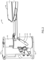
- FIG. 2 further illustrates a first position of the sleeve 108 corresponding to a deployed condition of the meal table 106.
- the fixed lateral post(s) 118, 122 are positioned at the upper end of their corresponding helical slot(s) 120, 124.
- the fully deployed position of the meal table 106 may also coincide with physical contact between the bottom of the sleeve 108 and a top of a lower plate 126 to which the fixed column 102 is mounted.
- the fixed column 102 is mounted vertically between the lower plate 126 and an upper plate 128 as discussed below.
- FIG. 3 illustrates the rotational lifting mechanism 116 by which the fixed column 102 and the sleeve 108 interact to synchronize rotational and vertical motion of the sleeve 108 relative to the fixed column 102 to move the sleeve 108 to a second position corresponding to a stowed condition of the meal table.
- the meal table may be manipulated by pushing the meal table away from the passenger (e.g., 'forward' direction), thereby causing the sleeve 108 to rotate around the fixed column 102 and at the same time undergo a vertical position change (e.g., raise) toward the upper plate 128.
- a vertical position change e.g., raise
- the length and steepness of the helical slots 120, 124 may be customized to control the angular rotation of the meal table between the fully stowed and fully deployed conditions.
- the length and steepness of the helical slots 120, 124 may be customized to provide a rotation angle of about 60 degrees and a vertical motion of about 2 inches.
- the sleeve 108 may rotate counterclockwise to stow and raise the meal table, and rotate clockwise to deploy and lower the meal table, or vice versa.
- FIG. 3 further illustrates an additional support element of the meal table assembly 100.
- a vertical support 130 is positioned radially outward of the sleeve 108 and includes a further helical slot 132.
- a bracket 134 may be mounted to the sleeve 108 such that the bracket 134 rotates with the sleeve 108 and is positioned between the sleeve 108 and the vertical support 130.
- the bracket 134 carries a further lateral post 136 engaged in and configured to travel along the further helical slot 132 to further, guide, support and synchronize the rotational and vertical motion of the sleeve 108 about the fixed column 102.
- FIG. 4 illustrates a latch and catch mechanism 138 of the meal table assembly 100 for maintaining the sleeve 108, and consequently the meal table, rotationally fixed relative to the fixed column 102.
- the latch and catch mechanism 138 includes a latch 140 carried on the bracket 134 such that the latch 140 is configured to rotate with the sleeve 108.
- a catch 142 is carried by the vertical support 130, for instance through an intermediate bracket 144 attached to the vertical support 130 which is rotationally fixed.
- the catch 142 may be inclined such that the latch 140 engages in the catch at the end of the 'upward' rotational motion of the sleeve 108 corresponding to the stowed condition of the meal table.
- the catch 142 may be released by actuating a release mechanism, for instance an actuator depressed to pull a Bowden cable having one end attached to a movable member of the catch 142.
- the latch 140 may automatically locate and be received in the catch 142 at the top of the motion, and be actuated to release the latch 140 from the catch 142 to allow the sleeve 108 to rotate the meal table down and toward the passenger.
- FIG. 5 illustrates a vertical lifting mechanism 146 of the meal table assembly 100.
- a gas spring 148 or like device is disposed vertically in the fixed column 102.
- the gas spring 148 includes a gas cylinder 150 and a reciprocating piston rod 152.
- a lateral post 154 is carried by the piston rod 152 and is configured to travel up and down vertically along a vertical slot 156 provided in the fixed column 102.
- the sleeve 108 further includes a horizontal slot 158.
- the lateral post 154 extends through each of the vertical slot 156 and the horizontal slot 158, in sequence. In use, the lateral post 154 travels up and down as the sleeve 108 rotates around the fixed column 102 allowable by the horizontal slot 158.
- the vertical lifting mechanism 146 may include a further lateral post 160 also carried by the piston rod 152, wherein the further lateral post 160 may be positioned diametrically opposite the lateral post 154.
- a further vertical slot 162 is provided in the fixed column 102 positioned diametrically opposite the vertical slot 156
- a further horizontal slot 164 is provided in the sleeve 108 positioned diametrically opposite the horizontal slot 158.
- the further lateral post 160 extends through each of the further vertical slot 164 and the further horizontal slot 164.
- the gas spring 150 operates to provide lift assistance to the sleeve 108, in contact with the lateral post(s) 154, 160, as the sleeve 108 is rotated in a first direction around the fixed column 102, and the gas spring 150 operates to store potential energy as the sleeve 108 is rotated in a second direction, opposite the first direction, around the fixed column 102.
- the gas springs 150 loads to damper the meal table motion as the meal table rotates and lowers toward the deployed position, and unloads to provide lift assistance as the meal table rotates toward the stowed position.
- FIG. 7 illustrates the positional relationships between the vertical slot 156 formed in the fixed column 102, the lateral post 154 carried by the piston rod, and the horizontal slot 158 formed in the sleeve 108.
- Each of the vertical slot 156 and the horizontal slot 158 has a length and relative position which allows the lateral post 154 to travel up and down vertically and the sleeve 108 to rotate around the fixed column 108.
- each of the slot lengths as described herein may be 'matched' such that the respective posts travel the full length of the slots as the table moves between the fully stowed and fully deployed positions.
- the sleeve 108 may further include a lateral feature for attaching the support arm to the sleeve 108.
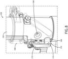
- FIG. 8 illustrates a locating feature of the meal table assembly 100.
- the locating feature includes a plurality of detents 168 formed in an outer circumferential surface of the fixed column 102. Each detent corresponds to a predefined position of the meal table.
- An opening 170 is provided through the sleeve 108.
- a spring lever 172 is mounted to the sleeve 108, and includes a detached end 174 disposed through the opening 170 provided in the sleeve 108 and configured to releasably engage in one of the plurality of detents 168 at a time to maintain the meal table in the corresponding predefined position.
- the detached end 174 may be rounded and the detents 168 correspondingly shaped such that the detached end 174 self-locates in the respective detent 168 and releases from the respective detent by the pushing or pulling force on the meal table.
- detents 168 may be positioned at the top, the bottom, and in at least one intermediate position of the meal table, corresponding to the stowed, deployed, and intermediate positions of the meal table.
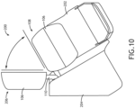
- FIGS. 9 and 10 illustrate the meal table assembly 100 in the context of a passenger seating arrangement 200.
- the passenger seating arrangement 200 includes a passenger seat 202, a console 204 positioned to one side of the passenger seat 202, and the meal table assembly 100 mounted to the console 204.
- the lower and upper plates 126, 128 shown in FIG. 2 may be upper and lower console portions to which the assembly components are attached.
- the console 204 may include a lateral slot through which the support arm 110 extends outside of the console 204. In this configuration, the majority of the meal table assembly 100 is housed and concealed within the console 204.
- FIG. 9 shows the upper and lower relative positions of the meal table 106 in each of the stowed position 206 and the deployed position 208.
- FIG. 10 shows the stowed and deployed positions 206, 208.
- the passenger seat 202 may be angled relative to the aircraft longitudinal axis
- the console 204 may be positioned along the fuselage wall or adjacent another seat console
- the meal table 106 stows forward of and generally to one side of the passenger seat 202.
- the meal table 106 may be folded when stowed and unfolded when deployed.
Landscapes
- Engineering & Computer Science (AREA)
- Aviation & Aerospace Engineering (AREA)
- Transportation (AREA)
- Mechanical Engineering (AREA)
- Accommodation For Nursing Or Treatment Tables (AREA)
Abstract
Description
- The present invention relates generally to meal tables for aircraft and other conveyances, and more particularly, to a deployable meal table with rotational lifting assistance and counterbalanced motion.
- Meal tables are commonly used in aircraft and other conveyances for dining and working. In economy seating classes, meal tables typically deploy from a stowed position against a backrest. In premium seating classes, meal tables may deploy from within an end bay or console.
- Meal tables associated with seating arrangements including side consoles typically require that the support arm translate toward and apart from the seat, and the table rotate between a vertical orientation for stowing and a horizontal orientation for deployment. As such, conventional meal table assemblies require horizontal tracks, rotating hinges, and a housing to store the meal table between uses. Such assemblies are complex, consume a significant amount of cabin space to implement, and do not allow the meal table to be usable when stowed.
- Therefore, what is needed is a meal table assembly that overcomes the disadvantages of conventional meal table solutions.
- According to one aspect, the invention provides a meal table assembly including a fixed column, a sleeve rotatably mounted on the fixed column, a support arm mounted at one end to the sleeve, and a meal table mounted on the support arm, and a rotational lifting mechanism. In embodiments, the rotational lifting mechanism includes a fixed lateral post mounted on the fixed column, and a helical slot provided in the sleeve. In use, the fixed lateral post and the helical slot are configured to interact to synchronize rotational and vertical motion of the sleeve relative to the fixed column.
- In some embodiments, the rotational lifting mechanism further includes a further fixed lateral post mounted on the fixed column, the further fixed lateral post positioned diametrically opposite the fixed lateral post, a further helical slot provided in the sleeve, the further helical slot positioned diametrically opposite the helical slot, and the further fixed lateral post and the further helical slot configured to interact to synchronize rotational and vertical motion of the sleeve relative to the fixed column.
- In some embodiments, the assembly further includes a vertical lifting mechanism including a gas spring disposed vertically in the fixed column, the gas spring including a gas cylinder and a reciprocating piston rod, a lateral post carried by the piston rod, a vertical slot provided in the fixed column, and a horizontal slot provided in the sleeve. In embodiments, the lateral post extends through each of the vertical slot and the horizontal slot such that, in use, the gas spring operates to provide lift assistance to the sleeve, in contact with the lateral post, as the sleeve is rotated in a first direction around the fixed column, and the gas spring operates to store potential energy as the sleeve is rotated in a second direction, opposite the first direction, around the fixed column.
- In some embodiments, the vertical lifting mechanism further includes a further lateral post carried by the piston rod, the further lateral post positioned diametrically opposite the lateral post, a further vertical slot provided in the fixed column, the further vertical slot positioned diametrically opposite the vertical slot, and a further horizontal slot provided in the sleeve, the further horizontal slot positioned diametrically opposite the horizontal slot. In embodiments, the further lateral post extends through each of the further vertical slot and the further horizontal slot such that, in use, the gas spring operates to provide lift assistance to the sleeve, in contact with the lateral post and the further lateral post, as the sleeve is rotated in a first direction around the fixed column, and the gas spring operates to store potential energy as the sleeve is rotated in a second direction, opposite the first direction, around the fixed column.
- In some embodiments, the meal table assembly further includes a vertical support positioned radially outward of the sleeve, the vertical support including a helical slot, a bracket mounted to the sleeve, the bracket disposed between the sleeve and the vertical support, and a lateral post mounted to the bracket, the lateral post engaged to travel along the helical slot to further synchronize rotational and vertical motion of the sleeve relative to the fixed column.
- In some embodiments, the meal table assembly further includes one of a latch and a catch carried by the vertical support and the other of the latch and the catch carried by the bracket, the latch and the catch configured to releasably engage to retain the sleeve at a top of its travel corresponding to a stowed position of the meal table.
- In some embodiments, the meal table assembly further includes a top plate attached to each of the fixed column and the vertical support, and a bottom plate attached to each of the fixed column and the vertical support.
- In some embodiments, the meal table assembly further includes a plurality of detents formed in an outer circumferential surface of the fixed column, each detent corresponding to a predefined position of the meal table, an opening provided through the sleeve, and a spring lever mounted to the sleeve, the spring lever having one end disposed through the opening provided in the sleeve and configured to releasably engage in one of the plurality of detents to maintain the meal table in the corresponding predefined position.
- In some embodiments, the meal table is a bifold table.
- According to another aspect, the invention provides a seating configuration including a passenger seat, a console positioned to one side of the passenger seat, and a meal table assembly associated with the console. In embodiments, the meal table assembly includes a fixed column disposed within the console, a sleeve rotatably mounted on the fixed column, a support arm mounted at one end to the sleeve, a portion of the support arm extending outside of the console, a meal table mounted on the portion of the support arm extending outside of the console, and a rotational lifting mechanism. In embodiments, the rotational lifting mechanism includes a fixed lateral post mounted on the fixed column, a helical slot provided in the sleeve, and the fixed lateral post and the helical slot configured to interact to synchronize rotational and vertical motion of the sleeve relative to the fixed column.
- According to a further aspect, the invention provides a console mountable meal table assembly including a fixed cylindrical column, a sleeve rotatably mounted on the fixed cylindrical column, a support arm mounted at one end to the sleeve, a meal table mounted on the support arm, and a rotational lifting mechanism configured to synchronize rotational and vertical motion of the sleeve relative to the fixed cylindrical column.
- This summary is provided solely as an introduction to subject matter that is fully described in the following detailed description and drawing figures. This summary should not be considered to describe essential features nor be used to determine the scope of the claims. Moreover, it is to be understood that both the foregoing summary and the following detailed description are explanatory only and are not necessarily restrictive of the subject matter claimed.
- Implementations of the inventive concepts disclosed herein may be better understood when consideration is given to the following detailed description thereof. Such description refers to the included drawings, which are not necessarily to scale, and in which some features may be exaggerated and some features may be omitted or may be represented schematically in the interest of clarity. Like reference numerals in the drawings may represent and refer to the same or similar element, feature, or function. In the drawings:
-
FIG. 1 is an isometric view of a meal table assembly shown from a first perspective, in accordance with example embodiments of this invention; -
FIG. 2 is a perspective viewing of the meal table assembly showing a first position of the meal table, in accordance with example embodiments of this invention; -
FIG. 3 is a detailed view of the meal table assembly showing a second position of the meal table, in accordance with example embodiments of this invention; -
FIG. 4 is a detailed view showing a latch and catch mechanism of the meal table assembly, in accordance with example embodiments of this invention; -
FIG. 5 is a sectional view of the meal table assembly showing a vertical lift mechanism in a first position, in accordance with example embodiments of this invention; -
FIG. 6 is a sectional view of the meal table assembly showing the vertical lift mechanism in a second position, in accordance with example embodiments of this invention; -
FIG. 7 is a detailed view of the meal table assembly showing features of the vertical lift mechanism, in accordance with example embodiments of this invention; -
FIG. 8 is a detailed view of the meal table assembly showing a lever and detent configuration for maintaining meal table positions, in accordance with example embodiments of this invention; -
FIG. 9 is a side elevation view showing the meal table assembly in the context of a seating arrangement, in accordance with example embodiments of this invention; and -
FIG. 10 is a top plan view showing the meal table in each of stowed and deployed positions, in accordance with example embodiments of this invention. - Before explaining at least one embodiment of the inventive concepts disclosed herein in detail, it is to be understood that the inventive concepts are not limited in their application to the details of construction and the arrangement of the components or steps or methodologies set forth in the following description or illustrated in the drawings. In the following detailed description of embodiments of the instant inventive concepts, numerous specific details are set forth in order to provide a more thorough understanding of the inventive concepts. However, it will be apparent to one of ordinary skill in the art having the benefit of the instant invention that the inventive concepts disclosed herein may be practiced without these specific details. In other instances, well-known features may not be described in detail to avoid unnecessarily complicating the instant invention. The inventive concepts disclosed herein are capable of other embodiments or of being practiced or carried out in various ways provided they fall within the scope of the claims. Also, it is to be understood that the phraseology and terminology employed herein is for the purpose of description and should not be regarded as limiting.
- As used herein, a letter following a reference numeral is intended to reference an embodiment of the feature or element that may be similar, but not necessarily identical, to a previously described element or feature bearing the same reference numeral (e.g., 1, 1a, 1b). Such shorthand notations are used for purposes of convenience only, and should not be construed to limit the inventive concepts disclosed herein in any way unless expressly stated to the contrary.
- Further, unless expressly stated to the contrary, "or" refers to an inclusive or and not to an exclusive or. For example, a condition A or B is satisfied by anyone of the following: A is true (or present) and B is false (or not present), A is false (or not present) and B is true (or present), and both A and B are true (or present).
- In addition, use of the "a" or "an" are employed to describe elements and components of embodiments of the instant inventive concepts. This is done merely for convenience and to give a general sense of the inventive concepts, and "a" and "an" are intended to include one or at least one and the singular also includes the plural unless it is obvious that it is meant otherwise.
- Finally, as used herein any reference to "one embodiment" or "some embodiments" means that a particular element, feature, structure, or characteristic described in connection with the embodiment is included in at least one embodiment of the inventive concepts disclosed herein. The appearances of the phrase "in some embodiments" in various places in the specification are not necessarily all referring to the same embodiment, and embodiments of the inventive concepts disclosed may include one or more of the features expressly described or inherently present herein, or any combination of sub-combination of two or more such features, along with any other features which may not necessarily be expressly described or inherently present in the instant invention.
- Broadly, embodiments of the inventive concepts disclosed herein are directed to a meal table assembly configured to be mounted to a console. The meal table is movable between a stowed position to one side of a passenger seat, and a deployed position overlying the passenger seat. The meal table assembly includes a mechanism configured to provide synchronous rotational and vertical motion such that the meal table raises when rotated to the stowed position, and lowers when rotated to the deployed position. The meal table motion is counterbalanced such that the meal table is configured to deploy substantially on its own in a slow dampened manner when unlatched, and feels substantially weightless to the passenger when being manually stowed. The meal table remains substantially horizontal to permit continued use when stowed while still allowing seat egress.
-
FIG. 1 illustrates ameal table assembly 100 according to the present invention. A fixedcolumn 102 defines a vertical axis ofrotation 104 about which a meal table 106 rotates or pivots between stowed and deployed positions of the meal table 106. Asleeve 108 is rotatably mounted on the fixedcolumn 102. In embodiments, the fixedcolumn 102 is cylindrical, thesleeve 108 is cylindrical, and the fixedcolumn 102 and thesleeve 108 are arranged concentric to one another. The length of thesleeve 108 is less than the length of the fixedcolumn 102 such that thesleeve 108 is able to travel up and down the fixedcolumn 102 to achieve the stowed and deployed positions as discussed below. - A
support arm 110 is mounted at one end to thesleeve 108. The meal table 106 is mounted on thesupport arm 110. In some embodiments, the meal table 106 may be movably mounted to thesupport arm 110 such that the meal table 106 can translate 'forward' and `aft' to provide further adjustability for the meal table 106. Translation may be achieved by a mechanism including guides and tracks that operates independent of the rotational lift assistance of themeal table assembly 100 discussed below. In some embodiments, the meal table 106 may be a bifold configuration including a first table 112 and a second table 114 hinged to the first table 112. In use, the second table 114 may be folded onto the first table 112 when the meal table 106 is stowed, and unfolded from the first table 112 when the meal table 106 is deployed to expand the table surface area. -
FIG. 2 illustrates arotational lifting mechanism 116 by which the fixedcolumn 102 and thesleeve 108 interact to synchronize rotational and vertical motion of thesleeve 108 relative to the fixedcolumn 102. In embodiments, therotational lifting mechanism 116 includes a fixedlateral post 118 mounted on the fixedcolumn 102, and ahelical slot 120 provided or formed in thesleeve 108. In use, the fixedlateral post 118 and thehelical slot 120 interact to synchronize the rotational and vertical motion of thesleeve 108 relative to the fixedcolumn 102. In embodiments, therotational lifting mechanism 116 includes a further fixed lateral post (see 122 inFIG. 7 ) mounted on the fixedcolumn 102 diametrically opposed to the fixedlateral post 118, and a further helical slot (see 124 inFIG. 7 ) provided in thesleeve 108 diametrically opposed to thehelical slot 120. In other words, themeal table assembly 100 may include a symmetrical arrangement of fixedlateral posts helical slots sleeve 108 relative to the fixedcolumn 102. In some embodiments, the fixedlateral posts -
FIG. 2 further illustrates a first position of thesleeve 108 corresponding to a deployed condition of the meal table 106. When in the fully deployed condition as shown, the fixed lateral post(s) 118, 122 are positioned at the upper end of their corresponding helical slot(s) 120, 124. In some embodiments, the fully deployed position of the meal table 106 may also coincide with physical contact between the bottom of thesleeve 108 and a top of alower plate 126 to which the fixedcolumn 102 is mounted. In embodiments, the fixedcolumn 102 is mounted vertically between thelower plate 126 and anupper plate 128 as discussed below. -
FIG. 3 illustrates therotational lifting mechanism 116 by which the fixedcolumn 102 and thesleeve 108 interact to synchronize rotational and vertical motion of thesleeve 108 relative to the fixedcolumn 102 to move thesleeve 108 to a second position corresponding to a stowed condition of the meal table. In use, the meal table may be manipulated by pushing the meal table away from the passenger (e.g., 'forward' direction), thereby causing thesleeve 108 to rotate around the fixedcolumn 102 and at the same time undergo a vertical position change (e.g., raise) toward theupper plate 128. The length and steepness of thehelical slots helical slots sleeve 108 may rotate counterclockwise to stow and raise the meal table, and rotate clockwise to deploy and lower the meal table, or vice versa. -
FIG. 3 further illustrates an additional support element of themeal table assembly 100. In embodiments, avertical support 130 is positioned radially outward of thesleeve 108 and includes a furtherhelical slot 132. Abracket 134 may be mounted to thesleeve 108 such that thebracket 134 rotates with thesleeve 108 and is positioned between thesleeve 108 and thevertical support 130. Thebracket 134 carries a furtherlateral post 136 engaged in and configured to travel along the furtherhelical slot 132 to further, guide, support and synchronize the rotational and vertical motion of thesleeve 108 about the fixedcolumn 102. -
FIG. 4 illustrates a latch andcatch mechanism 138 of themeal table assembly 100 for maintaining thesleeve 108, and consequently the meal table, rotationally fixed relative to the fixedcolumn 102. In embodiments, the latch andcatch mechanism 138 includes alatch 140 carried on thebracket 134 such that thelatch 140 is configured to rotate with thesleeve 108. Acatch 142 is carried by thevertical support 130, for instance through anintermediate bracket 144 attached to thevertical support 130 which is rotationally fixed. In embodiments, thecatch 142 may be inclined such that thelatch 140 engages in the catch at the end of the 'upward' rotational motion of thesleeve 108 corresponding to the stowed condition of the meal table. - Although not shown, the
catch 142 may be released by actuating a release mechanism, for instance an actuator depressed to pull a Bowden cable having one end attached to a movable member of thecatch 142. In use, thelatch 140 may automatically locate and be received in thecatch 142 at the top of the motion, and be actuated to release thelatch 140 from thecatch 142 to allow thesleeve 108 to rotate the meal table down and toward the passenger. -
FIG. 5 illustrates avertical lifting mechanism 146 of themeal table assembly 100. In embodiments, agas spring 148 or like device is disposed vertically in the fixedcolumn 102. Thegas spring 148 includes agas cylinder 150 and areciprocating piston rod 152. Alateral post 154 is carried by thepiston rod 152 and is configured to travel up and down vertically along avertical slot 156 provided in the fixedcolumn 102. Thesleeve 108 further includes ahorizontal slot 158. Thelateral post 154 extends through each of thevertical slot 156 and thehorizontal slot 158, in sequence. In use, thelateral post 154 travels up and down as thesleeve 108 rotates around the fixedcolumn 102 allowable by thehorizontal slot 158. - In embodiments, the
vertical lifting mechanism 146 may include a furtherlateral post 160 also carried by thepiston rod 152, wherein the furtherlateral post 160 may be positioned diametrically opposite thelateral post 154. Likewise, a furthervertical slot 162 is provided in the fixedcolumn 102 positioned diametrically opposite thevertical slot 156, and a furtherhorizontal slot 164 is provided in thesleeve 108 positioned diametrically opposite thehorizontal slot 158. The furtherlateral post 160 extends through each of the furthervertical slot 164 and the furtherhorizontal slot 164. - Referring to
FIGS. 5 and6 , is use, thegas spring 150 operates to provide lift assistance to thesleeve 108, in contact with the lateral post(s) 154, 160, as thesleeve 108 is rotated in a first direction around the fixedcolumn 102, and thegas spring 150 operates to store potential energy as thesleeve 108 is rotated in a second direction, opposite the first direction, around the fixedcolumn 102. For example, the gas springs 150 loads to damper the meal table motion as the meal table rotates and lowers toward the deployed position, and unloads to provide lift assistance as the meal table rotates toward the stowed position. -
FIG. 7 illustrates the positional relationships between thevertical slot 156 formed in the fixedcolumn 102, thelateral post 154 carried by the piston rod, and thehorizontal slot 158 formed in thesleeve 108. Each of thevertical slot 156 and thehorizontal slot 158 has a length and relative position which allows thelateral post 154 to travel up and down vertically and thesleeve 108 to rotate around the fixedcolumn 108. In embodiments, each of the slot lengths as described herein may be 'matched' such that the respective posts travel the full length of the slots as the table moves between the fully stowed and fully deployed positions. Thesleeve 108 may further include a lateral feature for attaching the support arm to thesleeve 108. -
FIG. 8 illustrates a locating feature of themeal table assembly 100. In embodiments, the locating feature includes a plurality ofdetents 168 formed in an outer circumferential surface of the fixedcolumn 102. Each detent corresponds to a predefined position of the meal table. Anopening 170 is provided through thesleeve 108. A spring lever 172 is mounted to thesleeve 108, and includes adetached end 174 disposed through theopening 170 provided in thesleeve 108 and configured to releasably engage in one of the plurality ofdetents 168 at a time to maintain the meal table in the corresponding predefined position. In embodiments, thedetached end 174 may be rounded and thedetents 168 correspondingly shaped such that thedetached end 174 self-locates in therespective detent 168 and releases from the respective detent by the pushing or pulling force on the meal table. In embodiments,detents 168 may be positioned at the top, the bottom, and in at least one intermediate position of the meal table, corresponding to the stowed, deployed, and intermediate positions of the meal table. -
FIGS. 9 and10 illustrate themeal table assembly 100 in the context of apassenger seating arrangement 200. In a non-limiting example, thepassenger seating arrangement 200 includes apassenger seat 202, aconsole 204 positioned to one side of thepassenger seat 202, and themeal table assembly 100 mounted to theconsole 204. In embodiments, the lower andupper plates FIG. 2 may be upper and lower console portions to which the assembly components are attached. Theconsole 204 may include a lateral slot through which thesupport arm 110 extends outside of theconsole 204. In this configuration, the majority of themeal table assembly 100 is housed and concealed within theconsole 204. -
FIG. 9 shows the upper and lower relative positions of the meal table 106 in each of the stowedposition 206 and the deployedposition 208.FIG. 10 shows the stowed and deployedpositions passenger seat 202 may be angled relative to the aircraft longitudinal axis, theconsole 204 may be positioned along the fuselage wall or adjacent another seat console, and the meal table 106 stows forward of and generally to one side of thepassenger seat 202. In addition, the meal table 106 may be folded when stowed and unfolded when deployed. - From the above description, it is clear that the inventive concepts disclosed herein are well adapted to achieve the objectives and to attain the advantages mentioned herein as well as those inherent in the inventive concepts disclosed herein. While presently preferred embodiments of the inventive concepts disclosed herein have been described for purposes of this invention, it will be understood that numerous changes may be made which fall within the scope of the invention as defined by the claims.
Claims (15)
- A meal table assembly (100), comprising:a fixed column (102);a sleeve (108) rotatably mounted on the fixed column;a support arm (110) mounted at one end to the sleeve;a meal table (106) mounted on the support arm; anda rotational lifting mechanism (116) comprising:a fixed lateral post (118) mounted on the fixed column;a helical slot (120) provided in the sleeve; andthe fixed lateral post and the helical slot configured to interact to synchronize rotational and vertical motion of the sleeve relative to the fixed column.
- The meal table assembly (100) according to claim 1, wherein the rotational lifting mechanism further comprises:a further fixed lateral post (122) mounted on the fixed column, the further fixed lateral post positioned diametrically opposite the fixed lateral post;a further helical slot (124) provided in the sleeve, the further helical slot positioned diametrically opposite the helical slot; andthe further fixed lateral post and the further helical slot configured to interact to synchronize rotational and vertical motion of the sleeve relative to the fixed column.
- The meal table assembly (100) according to claim 1 or 2, further comprising a vertical lifting mechanism, comprising:a gas spring (148) disposed vertically in the fixed column, the gas spring including a gas cylinder and a reciprocating piston rod;a lateral post (154) carried by the piston rod;a vertical slot (156) provided in the fixed column; anda horizontal slot (158) provided in the sleeve;wherein:the lateral post extends through each of the vertical slot and the horizontal slot;in use, the gas spring operates to provide lift assistance to the sleeve, in contact with the lateral post, as the sleeve is rotated in a first direction around the fixed column; andin use, the gas spring operates to store potential energy as the sleeve is rotated in a second direction, opposite the first direction, around the fixed column.
- The meal table assembly (100) according to claim 3, further comprising:a further lateral post (160) carried by the piston rod, the further lateral post positioned diametrically opposite the lateral post;a further vertical slot (162) provided in the fixed column, the further vertical slot positioned diametrically opposite the vertical slot; anda further horizontal slot (164) provided in the sleeve, the further horizontal slot positioned diametrically opposite the horizontal slot;wherein:the further lateral post extends through each of the further vertical slot and the further horizontal slot;in use, the gas spring operates to provide lift assistance to the sleeve, in contact with the lateral post and the further lateral post, as the sleeve is rotated in a first direction around the fixed column; andin use, the gas spring operates to store potential energy as the sleeve is rotated in a second direction, opposite the first direction, around the fixed column.
- The meal table assembly (100) according to any preceding claim, further comprising:a vertical support (130) positioned radially outward of the sleeve, the vertical support including a helical slot;a bracket (134) mounted to the sleeve, the bracket disposed between the sleeve and the vertical support; anda lateral post (136) mounted to the bracket, the lateral post engaged to travel along the helical slot to further synchronize rotational and vertical motion of the sleeve relative to the fixed column.
- The meal table assembly (100) according to claim 5, further comprising:one of a latch and a catch (138) carried by the vertical support; andthe other of the latch and the catch carried by the bracket;the latch and the catch configured to releasably engage to retain the sleeve at a top of its travel corresponding to a stowed position of the meal table.
- The meal table assembly (100) according to claim 5, further comprising:a top plate (128) attached to each of the fixed column and the vertical support; anda bottom plate (126) attached to each of the fixed column and the vertical support.
- The meal table assembly (100) according to any preceding claim, further comprising:a plurality of detents (168) formed in an outer circumferential surface of the fixed column, each detent corresponding to a predefined position of the meal table;an opening (170) provided through the sleeve; anda spring lever (172) mounted to the sleeve, the spring lever having one end disposed through the opening provided in the sleeve and configured to releasably engage in one of the plurality of detents to maintain the meal table in the corresponding predefined position.
- The meal table assembly (100) according to any preceding claim, wherein the meal table is a bifold table.
- A seating configuration (200), comprising:a passenger seat (202);a console (204) positioned to one side of the passenger seat; anda meal table assembly (208) associated with the console, the meal table assembly comprising:a fixed column (102) disposed within the console;a sleeve (108) rotatably mounted on the fixed column;a support arm (110) mounted at one end to the sleeve, a portion of the support arm extending outside of the console;a meal table (106) mounted on the portion of the support arm extending outside of the console; anda rotational lifting mechanism (116) comprising:a fixed lateral post (118) mounted on the fixed column;a helical slot (120) provided in the sleeve; andthe fixed lateral post and the helical slot configured to interact to synchronize rotational and vertical motion of the sleeve relative to the fixed column.
- The seating configuration (200) according to claim 10, wherein the rotational lifting mechanism further comprises:a further fixed lateral post (122) mounted on the fixed column, the further fixed lateral post positioned diametrically opposite the fixed lateral post;a further helical slot (124) provided in the sleeve, the further helical slot positioned diametrically opposite the helical slot; andthe further fixed lateral post and the further helical slot configured to interact to synchronize rotational and vertical motion of the sleeve relative to the fixed column.
- The seating configuration (200) according to claim 11, the meal table assembly further comprising a vertical lifting mechanism, comprising:a gas spring (148) disposed vertically in the fixed column, the gas spring including a gas cylinder and a reciprocating piston rod;a lateral post (154) carried by the piston rod;a vertical slot (156) provided in the fixed column; anda horizontal slot (158) provided in the sleeve;wherein:the lateral post extends through each of the vertical slot and the horizontal slot;in use, the gas spring operates to provide lift assistance to the sleeve, in contact with the lateral post, as the sleeve is rotated in a first direction around the fixed column; andin use, the gas spring operates to store potential energy as the sleeve is rotated in a second direction, opposite the first direction, around the fixed column.
- The seating configuration (200) according to claim 12, further comprising:a further lateral post (160) carried by the piston rod, the further lateral post positioned diametrically opposite the lateral post;a further vertical slot (162) provided in the fixed column, the further vertical slot positioned diametrically opposite the vertical slot; anda further horizontal slot (164) provided in the sleeve, the further horizontal slot positioned diametrically opposite the horizontal slot;wherein:the further lateral post extends through each of the further vertical slot and the further horizontal slot;in use, the gas spring operates to provide lift assistance to the sleeve, in contact with the lateral post and the further lateral post, as the sleeve is rotated in a first direction around the fixed column; andin use, the gas spring operates to store potential energy as the sleeve is rotated in a second direction, opposite the first direction, around the fixed column.
- The seating configuration (200) according to any of claims 10 to 13, further comprising:a vertical support (130) disposed within the console and positioned radially outward of the sleeve, the vertical support including a helical slot;a bracket mounted (134) to the sleeve, the bracket disposed between the sleeve and the vertical support; anda lateral post (136) mounted to the bracket, the lateral post engaged to travel along the helical slot to further synchronize rotational and vertical motion of the sleeve relative to the fixed column.
- The seating configuration (200) according to claim 14, further comprising:one of a latch and a catch (138) carried by the vertical support; andthe other of the latch and the catch carried by the bracket;the latch and the catch configured to releasably engage to retain the sleeve at a top of its travel corresponding to a stowed position of the meal table.
Applications Claiming Priority (1)
| Application Number | Priority Date | Filing Date | Title |
|---|---|---|---|
| US18/403,090 US12522359B2 (en) | 2024-01-03 | 2024-01-03 | Meal table with rotational lifting assistance |
Publications (2)
| Publication Number | Publication Date |
|---|---|
| EP4582342A1 true EP4582342A1 (en) | 2025-07-09 |
| EP4582342B1 EP4582342B1 (en) | 2026-04-01 |
Family
ID=94173018
Family Applications (1)
| Application Number | Title | Priority Date | Filing Date |
|---|---|---|---|
| EP25150046.8A Active EP4582342B1 (en) | 2024-01-03 | 2025-01-02 | Meal table with rotational lifting assistance |
Country Status (2)
| Country | Link |
|---|---|
| US (1) | US12522359B2 (en) |
| EP (1) | EP4582342B1 (en) |
Citations (3)
| Publication number | Priority date | Publication date | Assignee | Title |
|---|---|---|---|---|
| US5520122A (en) * | 1994-01-17 | 1996-05-28 | Fischer; Matthias | Furniture having a stationary top and articulated leaves |
| US7311354B2 (en) * | 2003-04-30 | 2007-12-25 | 3861589 Canada Inc. | Seat for aircraft |
| US20080120785A1 (en) * | 2006-08-31 | 2008-05-29 | Airbus | Aircraft subassembly and aircraft comprising such a subassembly |
Family Cites Families (22)
| Publication number | Priority date | Publication date | Assignee | Title |
|---|---|---|---|---|
| US5562049A (en) * | 1994-08-23 | 1996-10-08 | Helton, Inc. | Table with extendable and rotatable surfaces and mechanism for same |
| US5653499A (en) * | 1994-11-30 | 1997-08-05 | Goodall; Kirk Bryant | Chair bracket supporting keyboard and mouse platforms |
| US5573301A (en) * | 1995-05-16 | 1996-11-12 | Charles S. Fox | Table for chair |
| US6059357A (en) * | 1998-11-18 | 2000-05-09 | Bernhardt, L.L.C. | Chair with adjustable table |
| US6142559A (en) * | 1998-11-20 | 2000-11-07 | Steelcase Development Inc. | Seating product |
| US6726276B1 (en) * | 1999-02-25 | 2004-04-27 | Health Postures, Inc. | Synergistic body positioning and dynamic support system |
| US6422646B1 (en) * | 1999-04-29 | 2002-07-23 | Mcnally Michael Francis | Keyboard support |
| US6412862B1 (en) * | 2000-09-27 | 2002-07-02 | Randy Wayne Dickerson | Mounting socket for use with upholstered furniture |
| DE10260503A1 (en) * | 2002-12-21 | 2004-07-01 | Adam Opel Ag | Folding table arrangement for vehicles |
| US7216930B2 (en) * | 2004-08-18 | 2007-05-15 | Steenson Daniel V | Adjustable armchair tray |
| US8256835B2 (en) * | 2008-10-14 | 2012-09-04 | Irwin Seating Company | Seat with movable tablet |
| KR101188543B1 (en) * | 2010-11-19 | 2012-10-05 | 서원호 | A Chair |
| CN103687752B (en) * | 2011-01-03 | 2016-10-05 | 祖迪雅克座椅法国公司 | Pallet assembly |
| US8668257B2 (en) * | 2011-06-24 | 2014-03-11 | Yao-Chuan Wu | Foldable bracket of a chair |
| US8979190B2 (en) * | 2012-10-19 | 2015-03-17 | Demetrius Madrigal | Tray with armrest clamp |
| TW201326610A (en) | 2012-12-27 | 2013-07-01 | Ming-Jin Chen | Screw unit and lifting device using screw unit |
| GB2525381A (en) * | 2014-04-07 | 2015-10-28 | Zodiac Seats Uk Ltd | A table arrangement |
| GB2527047A (en) * | 2014-06-09 | 2015-12-16 | Zodiac Seats Uk Ltd | A table arrangement |
| KR101694017B1 (en) * | 2015-06-26 | 2017-01-06 | 현대자동차주식회사 | Foldable table assembly for vehicle |
| US11230381B2 (en) | 2019-05-07 | 2022-01-25 | B/E Aerospace, Inc. | Passenger suite with table mechanism with vertical, translational and rotational adjustment |
| EP3981287A1 (en) | 2020-10-06 | 2022-04-13 | USM U. Schärer Söhne AG | Raising column for furniture |
| US12151816B2 (en) * | 2022-10-11 | 2024-11-26 | B/E Aerospace, Inc. | Console mounted tray table with helical pivot |
-
2024
- 2024-01-03 US US18/403,090 patent/US12522359B2/en active Active
-
2025
- 2025-01-02 EP EP25150046.8A patent/EP4582342B1/en active Active
Patent Citations (3)
| Publication number | Priority date | Publication date | Assignee | Title |
|---|---|---|---|---|
| US5520122A (en) * | 1994-01-17 | 1996-05-28 | Fischer; Matthias | Furniture having a stationary top and articulated leaves |
| US7311354B2 (en) * | 2003-04-30 | 2007-12-25 | 3861589 Canada Inc. | Seat for aircraft |
| US20080120785A1 (en) * | 2006-08-31 | 2008-05-29 | Airbus | Aircraft subassembly and aircraft comprising such a subassembly |
Also Published As
| Publication number | Publication date |
|---|---|
| US20250214709A1 (en) | 2025-07-03 |
| US12522359B2 (en) | 2026-01-13 |
| EP4582342B1 (en) | 2026-04-01 |
Similar Documents
| Publication | Publication Date | Title |
|---|---|---|
| EP3741677B1 (en) | Position adjustable armrest assemblies for passenger seats | |
| EP3313733B1 (en) | Passenger seat table assembly | |
| EP2661381B1 (en) | Tray table assembly | |
| US11827360B2 (en) | Slide-out tray table with interlock assembly | |
| EP4217274B1 (en) | Slide-out tray table with interlock assembly | |
| CN111094064B (en) | Deployable table assembly | |
| EP4385898B1 (en) | Meal table for oblique seat installations and oblique seating arrangements | |
| US20180305023A1 (en) | Sequentially extending and rotating table mechanism | |
| US20220081118A1 (en) | Butterfly leafs for economy seat middle handle | |
| EP3736216B1 (en) | Passenger suite with table mechanism with vertical, translational and rotational adjustment | |
| US12522359B2 (en) | Meal table with rotational lifting assistance | |
| EP4353595B1 (en) | Console mounted tray table with helical pivot | |
| EP4015386B1 (en) | Cabin attendant seat with height adjustable seat pan | |
| US12617325B2 (en) | Support device for an aircraft cabin interior layout assembly, related assembly and method | |
| US20200354062A1 (en) | Passenger suite with table mechanism with vertical, translational and rotational adjustment | |
| US20220194593A1 (en) | Cabin attendant seat with height adjustable seat pan | |
| EP3971087A1 (en) | Butterfly leafs for economy seat middle handle | |
| EP3945021A1 (en) | Translating, locking, and rotating leg rest mechanism | |
| EP4140885B1 (en) | Movable oxygen container, and monument, passenger vehicle section and vehicle having the same | |
| US12479579B2 (en) | Passenger seat with self-stowing portable electronic device holder | |
| EP4396430B1 (en) | Aircraft interior assembly | |
| EP4488562B1 (en) | Portable electronic device holder with socket and rotating partial-cylinder |
Legal Events
| Date | Code | Title | Description |
|---|---|---|---|
| PUAI | Public reference made under article 153(3) epc to a published international application that has entered the european phase |
Free format text: ORIGINAL CODE: 0009012 |
|
| STAA | Information on the status of an ep patent application or granted ep patent |
Free format text: STATUS: REQUEST FOR EXAMINATION WAS MADE |
|
| 17P | Request for examination filed |
Effective date: 20250521 |
|
| AK | Designated contracting states |
Kind code of ref document: A1 Designated state(s): AL AT BE BG CH CY CZ DE DK EE ES FI FR GB GR HR HU IE IS IT LI LT LU LV MC ME MK MT NL NO PL PT RO RS SE SI SK SM TR |
|
| GRAJ | Information related to disapproval of communication of intention to grant by the applicant or resumption of examination proceedings by the epo deleted |
Free format text: ORIGINAL CODE: EPIDOSDIGR1 |
|
| GRAP | Despatch of communication of intention to grant a patent |
Free format text: ORIGINAL CODE: EPIDOSNIGR1 |
|
| GRAP | Despatch of communication of intention to grant a patent |
Free format text: ORIGINAL CODE: EPIDOSNIGR1 |
|
| STAA | Information on the status of an ep patent application or granted ep patent |
Free format text: STATUS: GRANT OF PATENT IS INTENDED |
|
| RIC1 | Information provided on ipc code assigned before grant |
Ipc: B64D 11/06 20060101AFI20251027BHEP Ipc: B60N 3/00 20060101ALI20251027BHEP Ipc: A47B 13/16 20060101ALI20251027BHEP Ipc: A47B 21/02 20060101ALI20251027BHEP |
|
| INTG | Intention to grant announced |
Effective date: 20251125 |
|
| GRAS | Grant fee paid |
Free format text: ORIGINAL CODE: EPIDOSNIGR3 |
|
| GRAA | (expected) grant |
Free format text: ORIGINAL CODE: 0009210 |
|
| STAA | Information on the status of an ep patent application or granted ep patent |
Free format text: STATUS: THE PATENT HAS BEEN GRANTED |
|
| AK | Designated contracting states |
Kind code of ref document: B1 Designated state(s): AL AT BE BG CH CY CZ DE DK EE ES FI FR GB GR HR HU IE IS IT LI LT LU LV MC ME MK MT NL NO PL PT RO RS SE SI SK SM TR |
|
| REG | Reference to a national code |
Ref country code: CH Ref legal event code: F10 Free format text: ST27 STATUS EVENT CODE: U-0-0-F10-F00 (AS PROVIDED BY THE NATIONAL OFFICE) Effective date: 20260401 Ref country code: GB Ref legal event code: FG4D |
|
| REG | Reference to a national code |
Ref country code: DE Ref legal event code: R096 Ref document number: 602025000076 Country of ref document: DE |
|
| REG | Reference to a national code |
Ref country code: IE Ref legal event code: FG4D |