EP4582338A1 - Bi-fold barrier system and method for a flight deck of an aircraft - Google Patents
Bi-fold barrier system and method for a flight deck of an aircraft Download PDFInfo
- Publication number
- EP4582338A1 EP4582338A1 EP24214847.6A EP24214847A EP4582338A1 EP 4582338 A1 EP4582338 A1 EP 4582338A1 EP 24214847 A EP24214847 A EP 24214847A EP 4582338 A1 EP4582338 A1 EP 4582338A1
- Authority
- EP
- European Patent Office
- Prior art keywords
- secondary barrier
- panel
- barrier door
- monument
- flight deck
- Prior art date
- Legal status (The legal status is an assumption and is not a legal conclusion. Google has not performed a legal analysis and makes no representation as to the accuracy of the status listed.)
- Pending
Links
Images






Classifications
-
- B—PERFORMING OPERATIONS; TRANSPORTING
- B64—AIRCRAFT; AVIATION; COSMONAUTICS
- B64D—EQUIPMENT FOR FITTING IN OR TO AIRCRAFT; FLIGHT SUITS; PARACHUTES; ARRANGEMENT OR MOUNTING OF POWER PLANTS OR PROPULSION TRANSMISSIONS IN AIRCRAFT
- B64D45/00—Aircraft indicators or protectors not otherwise provided for
- B64D45/0015—Devices specially adapted for the protection against criminal attack, e.g. anti-hijacking systems
- B64D45/0021—Devices specially adapted for the protection against criminal attack, e.g. anti-hijacking systems means for restricting access to flight deck
- B64D45/0026—Devices specially adapted for the protection against criminal attack, e.g. anti-hijacking systems means for restricting access to flight deck by creating a secure space between the flight deck and cabin
-
- B—PERFORMING OPERATIONS; TRANSPORTING
- B64—AIRCRAFT; AVIATION; COSMONAUTICS
- B64C—AEROPLANES; HELICOPTERS
- B64C1/00—Fuselages; Constructional features common to fuselages, wings, stabilising surfaces or the like
- B64C1/14—Windows; Doors; Hatch covers or access panels; Surrounding frame structures; Canopies; Windscreens accessories therefor, e.g. pressure sensors, water deflectors, hinges, seals, handles, latches, windscreen wipers
- B64C1/1407—Doors; surrounding frames
- B64C1/1469—Doors between cockpit and cabin
-
- B—PERFORMING OPERATIONS; TRANSPORTING
- B64—AIRCRAFT; AVIATION; COSMONAUTICS
- B64C—AEROPLANES; HELICOPTERS
- B64C1/00—Fuselages; Constructional features common to fuselages, wings, stabilising surfaces or the like
- B64C1/14—Windows; Doors; Hatch covers or access panels; Surrounding frame structures; Canopies; Windscreens accessories therefor, e.g. pressure sensors, water deflectors, hinges, seals, handles, latches, windscreen wipers
- B64C1/1407—Doors; surrounding frames
- B64C1/1461—Structures of doors or surrounding frames
-
- B—PERFORMING OPERATIONS; TRANSPORTING
- B64—AIRCRAFT; AVIATION; COSMONAUTICS
- B64D—EQUIPMENT FOR FITTING IN OR TO AIRCRAFT; FLIGHT SUITS; PARACHUTES; ARRANGEMENT OR MOUNTING OF POWER PLANTS OR PROPULSION TRANSMISSIONS IN AIRCRAFT
- B64D11/00—Passenger or crew accommodation; Flight-deck installations not otherwise provided for
- B64D11/0023—Movable or removable cabin dividers, e.g. for class separation
-
- B—PERFORMING OPERATIONS; TRANSPORTING
- B64—AIRCRAFT; AVIATION; COSMONAUTICS
- B64D—EQUIPMENT FOR FITTING IN OR TO AIRCRAFT; FLIGHT SUITS; PARACHUTES; ARRANGEMENT OR MOUNTING OF POWER PLANTS OR PROPULSION TRANSMISSIONS IN AIRCRAFT
- B64D45/00—Aircraft indicators or protectors not otherwise provided for
- B64D45/0015—Devices specially adapted for the protection against criminal attack, e.g. anti-hijacking systems
- B64D45/0021—Devices specially adapted for the protection against criminal attack, e.g. anti-hijacking systems means for restricting access to flight deck
-
- B—PERFORMING OPERATIONS; TRANSPORTING
- B64—AIRCRAFT; AVIATION; COSMONAUTICS
- B64D—EQUIPMENT FOR FITTING IN OR TO AIRCRAFT; FLIGHT SUITS; PARACHUTES; ARRANGEMENT OR MOUNTING OF POWER PLANTS OR PROPULSION TRANSMISSIONS IN AIRCRAFT
- B64D45/00—Aircraft indicators or protectors not otherwise provided for
- B64D45/0015—Devices specially adapted for the protection against criminal attack, e.g. anti-hijacking systems
- B64D45/0021—Devices specially adapted for the protection against criminal attack, e.g. anti-hijacking systems means for restricting access to flight deck
- B64D45/0028—Devices specially adapted for the protection against criminal attack, e.g. anti-hijacking systems means for restricting access to flight deck doors or door arrangements specially adapted to restrict unauthorized access
Definitions
- an aircraft in a particular implementation, includes a flight deck including a flight deck door configured to be moved between an open position and a closed position, a first monument, a second monument, and a secondary barrier door moveably secured between the first monument and the second monument.
- the secondary barrier door is configured to fold into a stowed position in which a path to the flight deck is open, and unfold into a deployed position in which the path to the flight deck is closed.
- the secondary barrier door includes a first panel, a second panel, and a pivot hinge pivotally coupling the first panel to the second panel.
- the first panel is folded adjacent to the first monument, and the second panel is folded adjacent to the first panel when the secondary barrier door is in the stowed position.
- the first panel is pivotally coupled to a lower pivot bearing secured to a floor, and an upper pivot bearing secured to a ceiling.
- the aircraft can also include a lower bearing and an upper bearing configured to receive and retain an end of the second panel when the secondary barrier door is in the deployed position.
- the pivot hinge can also include a lock configured to secure the secondary barrier door in a desired position.
- the secondary barrier door in the deployed position extends between the first monument and the second monument.
- a closed security vestibule is defined between the flight deck, the first monument, the second monument, and the secondary barrier door in the deployed position.
- the secondary barrier door is in front of a passenger seating area.
- the secondary barrier door includes an override device configured to allow the secondary barrier door to be removed.
- a method is provided as per the appended claims 11 to 15, and includes folding the secondary barrier door into the stowed position in which the path to the flight deck is open, and unfolding the secondary barrier into the deployed position in which the path to the flight deck is closed.
- FIG. 1 illustrates a simplified top view of a portion of an example internal cabin 100 of an aircraft 102.
- the internal cabin 100 includes a flight deck 104 (such as a cockpit) in which one or more pilots operate the aircraft 102.
- a primary flight deck door 106 is configured to be opened and closed to selectively allow and prevent access into the flight deck 104.
- the flight deck door 106 is generally reinforced and configured to be securely locked into a closed position.
- the flight deck door 106 generally extends between a floor 107 of the internal cabin 100 and to and into a frame, thereby reducing any open areas therebetween in the closed position.
- the flight deck door 106 is configured to pivot about a pivot axis 108, such as via one or more hinges, between the open position and the closed position.
- the pivot axis 108 is generally vertical in relation to the floor 107. In this manner, the flight deck door 106 is configured to pivot about a vertical axis between the open and closed position.
- a secondary barrier door 110 is moveably coupled in relation to one or more monuments 112 (for example, a first monument), 114 (for example, a second monument) that are aft (that is, rearwardly disposed) from the flight deck 104.
- the monument 112 can be a partition, a lavatory, a closet, a galley, or the like.
- the monument 114 can be a partition, a lavatory, a closet, a galley, or the like.
- the monument 112 may be across an aisle 116 from the monument 114.
- the secondary barrier door 110 can be moveably secured to the monuments 112 and/or 114.
- the secondary barrier door 110 can be moveably secured to a floor and/or ceiling, and spaced from the monuments 110 and/or 112.
- the secondary barrier door 110 includes a first panel 118 pivotally coupled to a second panel 120 by a pivot hinge 122, such as can include one or more axles pivotally retained within one or more sleeves.
- the first panel 118 and the second panel 120 can be sized and shaped the same.
- the first panel 118 can be larger or smaller than the second panel 120.
- the pivot hinge 122 defines a pivot axis 123.
- the pivot hinge 122 can include a single axle pivotally retained within a single reciprocal sleeve.
- the pivot hinge 122 can include two or more coaxial axles pivotally retained within two or more reciprocal sleeves.
- the first panel 118 may include a first end 124 and a second end 126.
- the first end 124 is pivotally coupled to one or more pivot bearings 128, which define a pivot axis 130.
- the pivot bearing(s) 128 are secured to one or more of the floor 107, a ceiling, and/or the monument 114.
- the second end 126 of the first panel 118 is coupled to the pivot hinge 122.
- the second panel 120 includes a first end 132 coupled to the pivot hinge 122, and a second end 134 that is distally located from the pivot hinge 122.
- the secondary barrier door 110 is configured to pivotally move between a stowed position 136, in which the secondary barrier door 110 is open, and a deployed position 138, in which the secondary barrier door 110 is closed.
- the secondary barrier door 110 is folded in relation to the one of the monuments 112 or 114, for example, in relation to the monument 114.
- the first panel 118 is substantially parallel (such as within +/- 5 degrees) with a wall 140 of the monument 112 or 114
- the second panel 120 is folded in relation to the first panel 118 to be substantially parallel (such as within +/- 5 degrees) with the first panel 118.
- the first panel 118 and the second panel 120 are configured to fold in relation to one another via the pivot hinge 122.
- the first panel 118 in the stowed position, is adjacent to (for example, abuts against) the wall 140 of for example the monument 114, and the second panel 120 is adjacent to (for example, abuts against) the first panel 118.
- the first panel 118 in the stowed position, can be spaced a distance from the wall 140 (such as 2 inches or less), and the second panel 120 can be spaced a distance from the first panel 118 9such as 2 inches or less).
- the second end 134 of the second panel 120 is grasped (such as via a handle) and moved toward the monument, for example the monument 112 across the aisle 116.
- the pivot hinge 122 rotates in the direction of arc A, while the first panel 118 pivots about the pivot axis 130 in the direction of arc B, thereby unfolding the secondary barrier door 110.
- the second panel 120 extends toward the monument, for example the monument 112, and the first panel 118 and the second panel 120 continue to pivot toward an aligned, coplanar state about the pivot hinge 122 until the second end 134 of the second panel 120 reaches the monument 112.
- the secondary barrier door 110 is fully extended (and unfolded), such that the secondary barrier door 110 is in the deployed position (and closed position).
- the process is reversed.
- the secondary barrier door 110 is pivoted into a folded position, and stowed adjacent to the monument, for example the monument 114, thereby providing an open path to the flight deck 104 (which can have the primary flight deck door 106 in a closed position).
- the secondary barrier door 110 is configured to pivotally move between the stowed position 136 and the deployed position 138.
- the secondary barrier door 110 includes the first panel 118 pivotally coupled to the second panel 120, such as via the pivot hinge 122.
- the first panel 118 and the second panel 120 are folded in relation to one another, and in relation to the monument, for example 114 (or 112).
- the deployed position 138 the first panel 118 and the second panel 120 are unfolded to extend between the monument 114 and the monument 112.
- the secondary barrier door 110 In the stowed position 136, the secondary barrier door 110 is open, such that a path 144 to the flight deck 104 is open.
- the path 144 can be a forward end 146 of the aisle 116 within the internal cabin 100.
- the secondary barrier door 110 In the deployed position 138, the secondary barrier door 110 extends across the path 144, between the monument 112 and the monument 114, thereby providing a closed barrier that blocks access to the flight deck 104.
- the secondary barrier door 110 extends between the monument 112 and the monument 114.
- the second end 134 can securely couple to one or more reciprocal structures, such as latches, bearings, and/or the like that retain the secondary barrier door 110 in the deployed position 138.
- the end 134 of the second panel 120 of the secondary barrier door 110 secures to one or more securing devices, such as latch(es) or lock(s), (such as on the floor, ceiling, and/or on the monument, for example monument 112) to securely lock the secondary barrier door 110 in the deployed position 138.
- the securing device(s) can be latches, bearings, manual locks, electronic locks, electromechanical locks, and/or the like.
- a closed security vestibule 150 is defined between the flight deck 104, the monument 112, the monument 114, and the secondary barrier door 110.
- the closed security vestibule 150 is closed off from a passenger seating area 151 of the internal cabin 100.
- the secondary barrier door 110 in the deployed position 138 provides a secure barrier that prevents access to the flight deck 104, even if the flight deck door 106 is in the open position.
- the secondary barrier door 110 is in front of (that is, closer to the fore end of the aircraft 102) the passenger seating area 151.
- the secondary barrier door 110 is not within the passenger seating area 151. Instead, the secondary barrier door 110 in the deployed position 138 prevents access from the passenger seating area 151 into the closed security vestibule 150.
- the secondary barrier door 110 is coupled to the floor 107, the ceiling, and/or the monument, for example the monument 114 by pivot bearing(s) 128 without a track. That is, there is no need for a guide track. Instead, the secondary barrier door 110 is configured to be moved between the stowed position 136 and the deployed position 138 without the use of a track, a retaining frame, and/or the like.
- Figure 10 illustrates a front view of the example secondary barrier door 110 in the stowed position 136.
- Figure 11 illustrates a front view of the example secondary barrier door 110 in a first intermediate position.
- Figure 12 illustrates a front view of the example secondary barrier door 110 in a second intermediate position.
- Figure 13 illustrates a front view of the example secondary barrier door 110 in the deployed position.
- the views shown in Figures 10-13 are from a position within the flight deck 104 looking aft.
- the secondary barrier door 110 is folded adjacent to the monument, for example the monument 114.
- the secondary barrier door 110 is pivoted about the pivot hinge 122 and extended to the monument 112, for example.
- orientations can be inverted, rotated, or otherwise changed, such that an upper portion is a lower portion, aft may be changed to forward, and vice versa, horizontal becomes vertical, and the like.
Landscapes
- Engineering & Computer Science (AREA)
- Aviation & Aerospace Engineering (AREA)
- Mechanical Engineering (AREA)
- Hinges (AREA)
Abstract
Description
- Examples of the present disclosure generally relate to bi-fold barrier systems and methods for a flight deck of an aircraft.
- Vehicles such as commercial aircraft are used to transport passengers between various locations. A commercial aircraft includes a flight deck (such as a cockpit) in which one or more pilots operate the aircraft.
- Flight deck doors are used to selectively open and close a flight deck. During a flight, a flight deck door is typically locked in a closed position to prevent passengers from entering into the flight deck. The flight deck door can be opened during a flight to allow crew members to access lavatory facilities, receive meals, and/or switch positions for resting purposes.
- The opening and closing of the flight deck door (referred to as "door transition") can reduce protective benefits of the flight deck door. In particular, when the flight deck door is opened, the flight deck is generally open. In order to ensure that passengers cannot enter into the flight deck during a door transition, a galley cart can be moved in position to provide a barrier to the flight deck. However, individuals may be able to move the galley cart, and gain access to the flight deck.
- A need exists for a barrier system and a method for preventing access to a flight deck during a door transition. Further, a need exists for an efficient and effective system and method for providing a secondary barrier to a flight deck.
- In a particular implementation, an aircraft is provided as per the appended claims 1 to 10, and includes a flight deck including a flight deck door configured to be moved between an open position and a closed position, a first monument, a second monument, and a secondary barrier door moveably secured between the first monument and the second monument. The secondary barrier door is configured to fold into a stowed position in which a path to the flight deck is open, and unfold into a deployed position in which the path to the flight deck is closed.
- In at least one example, the secondary barrier door includes a first panel, a second panel, and a pivot hinge pivotally coupling the first panel to the second panel. In at least one example, the first panel is folded adjacent to the first monument, and the second panel is folded adjacent to the first panel when the secondary barrier door is in the stowed position. In at least one example, the first panel is pivotally coupled to a lower pivot bearing secured to a floor, and an upper pivot bearing secured to a ceiling. The aircraft can also include a lower bearing and an upper bearing configured to receive and retain an end of the second panel when the secondary barrier door is in the deployed position. The pivot hinge can also include a lock configured to secure the secondary barrier door in a desired position.
- In at least one example, the secondary barrier door in the deployed position extends between the first monument and the second monument. In at least one example, a closed security vestibule is defined between the flight deck, the first monument, the second monument, and the secondary barrier door in the deployed position. In at least one example, the secondary barrier door is in front of a passenger seating area.
- In at least one example, the secondary barrier door includes an override device configured to allow the secondary barrier door to be removed.
- In another particular implementation, a method is provided as per the appended claims 11 to 15, and includes folding the secondary barrier door into the stowed position in which the path to the flight deck is open, and unfolding the secondary barrier into the deployed position in which the path to the flight deck is closed.
- The features, functions, and advantages described herein can be achieved independently in various implementations or may be combined in yet other implementations, further details of which can be found with reference to the following description and drawings.
-
-
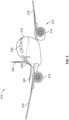
Figure 1 illustrates a simplified top view of a portion of an example internal cabin of an aircraft. -
Figure 2 illustrates a perspective front view of an example aircraft. -
Figure 3A illustrates a top plan view of an example internal cabin of an aircraft. -
Figure 3B illustrates a top plan view of an example internal cabin of an aircraft. -
Figure 4 illustrates a perspective interior view of an example internal cabin of an aircraft. -
Figure 5 illustrates a perspective front view of an example secondary barrier door in a stowed position. -
Figure 6 illustrates a perspective front view of the example secondary barrier door ofFigure 5 in a deployed position. -
Figure 7 illustrates a lateral view of the example secondary barrier door in the stowed position. -
Figure 8 illustrates a perspective top view of the example secondary barrier door in the stowed position. -
Figure 9 illustrates a perspective top view of the example secondary barrier door ofFigure 8 in the deployed position. -
Figure 10 illustrates a front view of the example secondary barrier door in the stowed position. -
Figure 11 illustrates a front view of the example secondary barrier door in a first intermediate position. -
Figure 12 illustrates a front view of the example secondary barrier door in a second intermediate position. -
Figure 13 illustrates a front view of the example secondary barrier door in the deployed position. -
Figure 14 illustrates a perspective view of a lower portion of the example secondary barrier door. -
Figure 15 illustrates a perspective view of an example upper pivot bearing mounted to a ceiling. -
Figure 16 illustrates a perspective view of an example override device secured to a first panel. -
Figure 17 illustrates a perspective partially exploded view of an example override device. -
Figure 18 illustrates a perspective view of an example override device. -
Figure 19 illustrates a perspective view of an example upper bearing retaining an upper portion of an end of a second panel. -
Figure 20 illustrates a perspective view of an example lower bearing retaining a lower portion of the end of the second panel. -
Figure 21 illustrates a plan view of an example bearing retaining the end of the second panel. -
Figure 22 illustrates a flow chart of an example method. - The foregoing summary, as well as the following detailed description of certain embodiments will be better understood when read in conjunction with the appended drawings. As used herein, an element or step recited in the singular and preceded by the word "a" or "an" should be understood as not necessarily excluding the plural of the elements or steps. Further, references to "one embodiment" are not intended to be interpreted as excluding the existence of additional embodiments that also incorporate the recited features. Moreover, unless explicitly stated to the contrary, embodiments "comprising" or "having" an element or a plurality of elements having a particular condition can include additional elements not having that condition.
-
Figure 1 illustrates a simplified top view of a portion of an exampleinternal cabin 100 of anaircraft 102. Theinternal cabin 100 includes a flight deck 104 (such as a cockpit) in which one or more pilots operate theaircraft 102. A primaryflight deck door 106 is configured to be opened and closed to selectively allow and prevent access into theflight deck 104. Theflight deck door 106 is generally reinforced and configured to be securely locked into a closed position. Theflight deck door 106 generally extends between afloor 107 of theinternal cabin 100 and to and into a frame, thereby reducing any open areas therebetween in the closed position. Theflight deck door 106 is configured to pivot about apivot axis 108, such as via one or more hinges, between the open position and the closed position. Thepivot axis 108 is generally vertical in relation to thefloor 107. In this manner, theflight deck door 106 is configured to pivot about a vertical axis between the open and closed position. - In order to protect the
flight deck 104 during a door transition, asecondary barrier door 110 is moveably coupled in relation to one or more monuments 112 (for example, a first monument), 114 (for example, a second monument) that are aft (that is, rearwardly disposed) from theflight deck 104. For example, themonument 112 can be a partition, a lavatory, a closet, a galley, or the like. Similarly, themonument 114 can be a partition, a lavatory, a closet, a galley, or the like. As an example, themonument 112 may be across anaisle 116 from themonument 114. Thesecondary barrier door 110 can be moveably secured to themonuments 112 and/or 114. As another example, thesecondary barrier door 110 can be moveably secured to a floor and/or ceiling, and spaced from themonuments 110 and/or 112. - In some examples, the
secondary barrier door 110 includes afirst panel 118 pivotally coupled to asecond panel 120 by apivot hinge 122, such as can include one or more axles pivotally retained within one or more sleeves. Thefirst panel 118 and thesecond panel 120 can be sized and shaped the same. Optionally, thefirst panel 118 can be larger or smaller than thesecond panel 120. - The
pivot hinge 122 defines apivot axis 123. For example, thepivot hinge 122 can include a single axle pivotally retained within a single reciprocal sleeve. As another example, thepivot hinge 122 can include two or more coaxial axles pivotally retained within two or more reciprocal sleeves. Thefirst panel 118 may include afirst end 124 and asecond end 126. Thefirst end 124 is pivotally coupled to one ormore pivot bearings 128, which define apivot axis 130. The pivot bearing(s) 128 are secured to one or more of thefloor 107, a ceiling, and/or themonument 114. Thesecond end 126 of thefirst panel 118 is coupled to thepivot hinge 122. Thesecond panel 120 includes afirst end 132 coupled to thepivot hinge 122, and asecond end 134 that is distally located from thepivot hinge 122. - In operation, the
secondary barrier door 110 is configured to pivotally move between a stowedposition 136, in which thesecondary barrier door 110 is open, and a deployedposition 138, in which thesecondary barrier door 110 is closed. In the stowed position, thesecondary barrier door 110 is folded in relation to the one of themonuments monument 114. In particular, in the stowed position, thefirst panel 118 is substantially parallel (such as within +/- 5 degrees) with awall 140 of themonument second panel 120 is folded in relation to thefirst panel 118 to be substantially parallel (such as within +/- 5 degrees) with thefirst panel 118. Thefirst panel 118 and thesecond panel 120 are configured to fold in relation to one another via thepivot hinge 122. - In at least one example, in the stowed position, the
first panel 118 is adjacent to (for example, abuts against) thewall 140 of for example themonument 114, and thesecond panel 120 is adjacent to (for example, abuts against) thefirst panel 118. Optionally, in the stowed position, thefirst panel 118 can be spaced a distance from the wall 140 (such as 2 inches or less), and thesecond panel 120 can be spaced a distance from thefirst panel 118 9such as 2 inches or less). - In order to close the
secondary barrier door 110, thesecond end 134 of thesecond panel 120 is grasped (such as via a handle) and moved toward the monument, for example themonument 112 across theaisle 116. As thesecond panel 120 is moved toward themonument 112, thepivot hinge 122 rotates in the direction of arc A, while thefirst panel 118 pivots about thepivot axis 130 in the direction of arc B, thereby unfolding thesecondary barrier door 110. As thesecondary barrier door 110 continues to unfold in such manner, thesecond panel 120 extends toward the monument, for example themonument 112, and thefirst panel 118 and thesecond panel 120 continue to pivot toward an aligned, coplanar state about thepivot hinge 122 until thesecond end 134 of thesecond panel 120 reaches themonument 112. When thesecond panel 120 reaches themonument 112, thesecondary barrier door 110 is fully extended (and unfolded), such that thesecondary barrier door 110 is in the deployed position (and closed position). - In order to move the
secondary barrier door 110 from the deployedposition 138 into the stowedposition 136, the process is reversed. In particular, thesecondary barrier door 110 is pivoted into a folded position, and stowed adjacent to the monument, for example themonument 114, thereby providing an open path to the flight deck 104 (which can have the primaryflight deck door 106 in a closed position). - As described herein, the
secondary barrier door 110 is configured to pivotally move between the stowedposition 136 and the deployedposition 138. Thesecondary barrier door 110 includes thefirst panel 118 pivotally coupled to thesecond panel 120, such as via thepivot hinge 122. In the stowedposition 136, thefirst panel 118 and thesecond panel 120 are folded in relation to one another, and in relation to the monument, for example 114 (or 112). In the deployedposition 138, thefirst panel 118 and thesecond panel 120 are unfolded to extend between themonument 114 and themonument 112. - In the stowed
position 136, thesecondary barrier door 110 is open, such that apath 144 to theflight deck 104 is open. Thepath 144 can be aforward end 146 of theaisle 116 within theinternal cabin 100. In the deployedposition 138, thesecondary barrier door 110 extends across thepath 144, between themonument 112 and themonument 114, thereby providing a closed barrier that blocks access to theflight deck 104. - In the deployed
position 138, thesecondary barrier door 110 extends between themonument 112 and themonument 114. In the deployed position, thesecond end 134 can securely couple to one or more reciprocal structures, such as latches, bearings, and/or the like that retain thesecondary barrier door 110 in the deployedposition 138. For example, theend 134 of thesecond panel 120 of thesecondary barrier door 110 secures to one or more securing devices, such as latch(es) or lock(s), (such as on the floor, ceiling, and/or on the monument, for example monument 112) to securely lock thesecondary barrier door 110 in the deployedposition 138. The securing device(s) can be latches, bearings, manual locks, electronic locks, electromechanical locks, and/or the like. Thesecond panel 120 of thesecondary barrier door 110 can also include a handle, strap, or the like that is configured to allow an individual to grasp thesecondary barrier door 110 and unfold thesecondary barrier door 110 into the deployedposition 138, and fold thesecondary barrier door 110 into the stowedposition 136. - When the secondary barrier door 110 (which is aft from the flight deck door 106) is in the deployed
position 138, aclosed security vestibule 150 is defined between theflight deck 104, themonument 112, themonument 114, and thesecondary barrier door 110. Theclosed security vestibule 150 is closed off from apassenger seating area 151 of theinternal cabin 100. As such, thesecondary barrier door 110 in the deployedposition 138 provides a secure barrier that prevents access to theflight deck 104, even if theflight deck door 106 is in the open position. - The
secondary barrier door 110 is in front of (that is, closer to the fore end of the aircraft 102) thepassenger seating area 151. Thesecondary barrier door 110 is not within thepassenger seating area 151. Instead, thesecondary barrier door 110 in the deployedposition 138 prevents access from thepassenger seating area 151 into theclosed security vestibule 150. - In at least one example, the
secondary barrier door 110 is coupled to thefloor 107, the ceiling, and/or the monument, for example themonument 114 by pivot bearing(s) 128 without a track. That is, there is no need for a guide track. Instead, thesecondary barrier door 110 is configured to be moved between the stowedposition 136 and the deployedposition 138 without the use of a track, a retaining frame, and/or the like. - As shown, according to one implementation, the
secondary barrier door 110 in the stowedposition 136 is folded adjacent to (for example, against) themonument 114. Optionally, thesecondary barrier door 110 in the stowedposition 136 can be folded adjacent to (for example, against) themonument 112, and configured to extend toward themonument 114 into the deployedposition 138. - As described herein, the
aircraft 102 includes theinternal cabin 100 having theflight deck 104 including theflight deck door 106 configured to be moved between an open position and a closed position. Theinternal cabin 100 also includes thefirst monument second monument secondary barrier door 110 is moveably secured between thefirst monument second monument secondary barrier door 110 is configured to fold into the stowedposition 136 in which thepath 144 to theflight deck 104 is open, and unfold into the deployedposition 138 in which thepath 144 to theflight deck 104 is closed. In at least one example, thesecondary barrier door 110 includes thefirst panel 118, thesecond panel 120, and thepivot hinge 122 pivotally coupling thefirst panel 118 to thesecond panel 120. In at least one example, thefirst panel 118 is folded adj acent to the monument (for example the monument 114), and thesecond panel 120 is folded adjacent to thefirst panel 118 when thesecondary barrier door 110 is in the stowedposition 136. Thesecondary barrier door 110 in the deployedposition 138 extends between thefirst monument second monument closed security vestibule 150 is defined between theflight deck 104, thefirst monument second monument secondary barrier door 110 in the deployedposition 138. -
Figure 2 illustrates a perspective front view of anexample aircraft 210. Theaircraft 210 is an example of theaircraft 102, shown inFigure 1 . Theaircraft 210 includes apropulsion system 212 that includesengines 214, for example. Optionally, thepropulsion system 212 may includemore engines 214 than shown. Theengines 214 are carried bywings 216 of theaircraft 210. In other examples, theengines 214 may be carried by afuselage 218 and/or anempennage 220. Theempennage 220 may also supporthorizontal stabilizers 222 and avertical stabilizer 224. - The
fuselage 218 of theaircraft 210 defines aninternal cabin 230, which includes a flight deck, one or more work sections (for example, galleys, personnel carry-on baggage areas, and the like), one or more passenger sections (for example, first class, business class, and coach sections), one or more lavatories, and/or the like. Theinternal cabin 230 is an example of theinternal cabin 100, as shown inFigure 1 . - Alternatively, instead of an aircraft, examples of the present disclosure may be used with various other vehicles, such as automobiles, buses, locomotives and train cars, watercraft, and the like. Further, examples of the present disclosure may be used with respect to fixed structures, such as commercial and residential buildings.
- According to some implementations, an aircraft can be provided, comprising the
flight deck 104 including theflight deck door 106 configured to be moved between an open position and a closed position, thefirst monument second monument secondary barrier door 110 in front of thepassenger seating area 151, wherein thesecondary barrier door 110 is moveably secured between thefirst monument second monument secondary barrier door 110 is configured to fold into the stowedposition 136 in which thepath 144 to theflight deck 104 is open, and unfold into a deployedposition 138 in which thepath 144 to theflight deck 104 is closed, wherein thesecondary barrier door 110 in the deployedposition 138 extends between thefirst monument second monument closed security vestibule 150 is defined between theflight deck 104, thefirst monument second monument secondary barrier door 110 in the deployedposition 138. Thesecondary barrier door 110 within the aircraft may further comprise thefirst panel 118, thesecond panel 120, and thepivot hinge 122 pivotally coupling thefirst panel 118 to thesecond panel 120, wherein thefirst panel 118 is folded adjacent to thefirst monument second panel 120 is folded adjacent to thefirst panel 118 when thesecondary barrier door 110 is in the stowedposition 136, wherein thefirst panel 118 is pivotally coupled to a lower pivot bearing 128a (discussed below) secured to thefloor 107, and an upper pivot bearing 128b (discussed below) secured to theceiling 109, and wherein thepivot hinge 122 may comprise alock 125 configured to secure thesecondary barrier door 110 in a desired position. Thesecondary barrier door 110 within the aircraft may further comprise an override device 500 (discussed below) configured to allow thesecondary barrier door 110 to be removed; and alower bearing 160a (discussed below) and anupper bearing 160b (discussed below) configured to receive and retain an end of thesecond panel 120 when thesecondary barrier door 110 is in the deployedposition 138. -
Figure 3A illustrates a top plan view of an exampleinternal cabin 230 of an aircraft. Theinternal cabin 230 may be within thefuselage 232 of the aircraft, such as thefuselage 218 ofFigure 2 . For example, one or more fuselage walls may define theinternal cabin 230. Theinternal cabin 230 includes multiple areas, including afront section 233, a first-class section 234, abusiness class section 236, one or more galley stations, an expanded economy orcoach section 240, a standard economy ofcoach section 242, and anaft section 244. It is to be understood that theinternal cabin 230 may include more or less areas than shown. For example, theinternal cabin 230 may not include a first-class section, and may include more or less galley stations than shown. Each of the sections may be separated by a cabin transition area, which may include class divider assemblies between aisles. - As shown in
Figure 3A , the exampleinternal cabin 230 includes twoaisles aft section 244. Optionally, theinternal cabin 230 may have fewer or more aisles than shown. For example, theinternal cabin 230 may include a single aisle that extends through the center of theinternal cabin 230 that leads to theaft section 244. -
Figure 3B illustrates a top plan view of an exampleinternal cabin 280 of an aircraft. Theinternal cabin 280 is an example of theinternal cabin 230 shown inFigure 2 . Theinternal cabin 280 may be within afuselage 281 of the aircraft. For example, one or more fuselage walls may define theinternal cabin 280. Theinternal cabin 280 includes multiple areas, including amain cabin 282 having passenger seats, and anaft section 285 behind themain cabin 282. It is to be understood that theinternal cabin 280 may include more or less areas than shown. - The
internal cabin 280 may include asingle aisle 284 that leads to theaft section 285. Thesingle aisle 284 may extend through the center of theinternal cabin 280 that leads to theaft section 285. For example, thesingle aisle 284 may be coaxially aligned with a central longitudinal plane of theinternal cabin 280. The aisle can optionally be offset from a centerline of the fuselage. -
Figure 4 illustrates a perspective interior view of an exampleinternal cabin 300 of an aircraft. Theinternal cabin 300 is an example of theinternal cabin 100 shown inFigure 1 . Theinternal cabin 300 includesoutboard walls 302 connected to aceiling 304.Windows 306 may be formed within theoutboard walls 302. Afloor 308 supports rows ofseats 310. As shown inFigure 4 , arow 312 may include twoseats 310 on either side of anaisle 313. However, therow 312 may include more orless seats 310 than shown. Additionally, theinternal cabin 300 may include more aisles than shown. - A
flight deck door 316 is at an aft end of a flight deck. Theflight deck door 316 in the closed position closes access into the flight deck. - Overhead
stowage bin assemblies 318 are secured to theceiling 304 and/or theoutboard wall 302. The overheadstowage bin assemblies 318 are secured over theseats 310. The overheadstowage bin assemblies 318 extend between the front and rear end of theinternal cabin 300. Eachstowage bin assembly 318 may include a pivot bin orbucket 320 pivotally secured to a strongback. The overheadstowage bin assemblies 318 are configured to be pivoted open in order to receive passenger carry-on baggage and personal items, for example. -
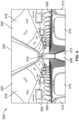
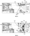
Figure 5 illustrates a perspective front view of the examplesecondary barrier door 110 in the stowedposition 136.Figure 6 illustrates a perspective view of the examplesecondary barrier door 110 ofFigure 5 in the deployedposition 138.Figure 7 illustrates a lateral view of the examplesecondary barrier door 110 in the stowedposition 136.Figure 8 illustrates a perspective top view of the examplesecondary barrier door 110 in the stowed position.Figure 9 illustrates a perspective top view of the examplesecondary barrier door 110 ofFigure 8 in the deployed position. - Referring to
Figures 5-9 , thefirst panel 118 and thesecond panel 120 can be sized and shaped the same. For example, thefirst panel 118 and thesecond panel 120 can be mirror image structures. Optionally, thefirst panel 118 and thesecond panel 120 can be sized and shaped differently from one another. - In at least one example, the
pivot hinge 122 is disposed between central portions of thefirst panel 118 and thesecond panel 120. Thepivot hinge 122 can also include a securing device, such as alock 125, that is configured to selectively lock thesecondary barrier door 110 in a desired position, such as the stowedposition 136 and/or the deployedposition 138. In at least one example, thepivot hinge 122 can be a piano hinge. Thepivot hinge 122 is configured to join thefirst panel 118 to thesecond panel 120, and can include thelock 125 that securely locks thesecondary barrier door 110 in the deployedposition 138. Thelock 125 can be engaged by a user to selectively lock and unlock thepivot hinge 122. Optionally, thepivot hinge 122 may not include a lock. - The
first panel 118 may be, in some implementations, pivotally coupled to thelower pivot bearing 128a secured to thefloor 107, and the upper pivot bearing 128b secured to theceiling 109. Thelower bearing 160a is secured to thefloor 107 proximate to the monument, for example themonument 112, and theupper bearing 160b is secured to theceiling 109 proximate to the monument, for example themonument 112. Thelower bearing 160a and theupper bearing 160b are configured to receive and retain theend 134 at lower and upper areas, respectively, when thesecondary barrier door 110 is in the deployedposition 138. Optionally, only thebearing 160a or thebearing 160b can be used. In at least one other example, thesecondary barrier door 110 does not engage any bearing. - As shown, the
second panel 120 can include ahandle 164, which can be disposed on both sides of thesecond panel 120. Thehandle 164 allows an individual to grasp thesecond panel 120 and readily move thesecondary barrier door 110 between the stowedposition 136 and the deployedposition 138. - As described herein, the
secondary barrier door 110 includes thefirst panel 118 pivotally coupled to thesecond panel 120 to provide a bi-fold door, which can extend between thefloor 107 and theceiling 109. In the stowedposition 136, thesecondary barrier door 110 is folded, such that an aft face 178 (that is, a surface configured to face aft when thesecondary barrier door 110 is in the deployed position 138) of thefirst panel 118 faces anaft face 180 of thesecond panel 120. In the stowedposition 136, theaft face 178 is adjacent (and can abut against) theaft face 180. Further, in the stowedposition 136, a fore face 182 (that is, a surface configured to face forward when thesecondary barrier door 110 is in the deployed position 138) of thefirst panel 118 is adjacent to thewall 140 of the monument (for example 114), while afore face 184 of thesecond panel 120 faces, and is spaced apart from, the monument (for example 112). - The
first panel 118 and thesecond panel 120 can also includeopenings 190, such as open channels, windows, screens, and/or the like formed therethrough. Theopenings 190 allow for viewing therethrough. Optionally, one or both of thefirst panel 118 and/or thesecond panel 120 may not include an opening. -
Figure 10 illustrates a front view of the examplesecondary barrier door 110 in the stowedposition 136.Figure 11 illustrates a front view of the examplesecondary barrier door 110 in a first intermediate position.Figure 12 illustrates a front view of the examplesecondary barrier door 110 in a second intermediate position.Figure 13 illustrates a front view of the examplesecondary barrier door 110 in the deployed position. The views shown inFigures 10-13 are from a position within theflight deck 104 looking aft. As described herein, in the stowedposition 136, thesecondary barrier door 110 is folded adjacent to the monument, for example themonument 114. In order to move thesecondary barrier door 110 into the deployedposition 138, thesecondary barrier door 110 is pivoted about thepivot hinge 122 and extended to themonument 112, for example. -
Figure 14 illustrates a perspective view of a lower portion of the examplesecondary barrier door 110. Thelower pivot bearing 128a can include a base 400 mounted to thefloor 107. Apivot axle 402 extends upwardly from thebase 400. A portion of thepivot axle 402 is pivotally retained within a reciprocal retainer 404 (such as a sleeve, cuff, tube, and/or the like) of thefirst panel 118. The upper pivot bearing 128b can be similarly configured, and secured to theceiling 109, as described in relation toFigures 5-9 . -
Figure 15 illustrates a perspective view of an example upper pivot bearing 128b mounted to aceiling 109. In this example, the upper pivot bearing 128b can be secured to theceiling 109 using standard inserts (or tie-in secondary supports). The upper pivot bearing 128b receives anupper pin 410 extending upwardly from thefirst panel 118. The upper pivot bearing 128b can be configured to constrain thepin 410 in two axes (such as an X axis and a Y axis), but allow for linear shifting in a third axis (such as a Z axis). The upper pivot bearing 128b can allow an axis of rotation to be fit/faired at installation using slotted features. The upper pivot bearing 128b can also include dampers, such as elastomeric dampers, to reduce noise during operation. -
Figure 16 illustrates a perspective view of anexample override device 500 secured to thefirst panel 118. In at least one example, thesecondary barrier door 110 includes an override device, such as theoverride device 500. Theoverride device 500 is configured to allow thesecondary barrier door 110 to be completely removed, if desired. For example, in some implementations, theoverride device 500 may be configured to allow thesecondary barrier door 110 to be completely removed out of thelower pivot bearing 128a, or thefloor 107. Alternatively, in some implementations, theoverride device 500 may be configured to allow thesecondary barrier door 110 to be completely removed out of the upper pivot bearing 128b, or theceiling 109. In some examples, as for example shown inFigure 18 , theoverride device 500 may be configured to allow thesecondary barrier door 110 to be completely removed out of the upper and lower pivot bearings (128a, 128b). Anoverride device 500 can be secured at a lower end and an upper end of thefirst panel 118. - As an example, the
override device 500 can include acompression spring 502 configured to engage a pivot pin or axle 504 (for example, thepivot axle 504 pivotally retained within the first panel 118), and anaccessible cap screw 506, which provides a release mechanism. Thecap screw 506 can be engaged to compress thespring 502 and disengage theaxle 504, thereby allowing the first panel 118 (and therefore the secondary barrier door 110) to be removed from pivot bearings, such as for example, the upper pivot bearing 128b and/orlower pivot bearing 128a. -
Figure 17 illustrates a perspective partially exploded view of anexample override device 500, for example theoverride device 500 comprising the features shown inFigure 16 . In this example, acover plate 508 can be used to cover thecap screw 506. Thecover plate 508 can be fastened to a housing with acaptive thumbscrew 512. -
Figure 18 illustrates a perspective view of anexample override device 500. In this example, theoverride device 500 can be or otherwise include arotary mechanism 520, having ahandle 522 which can be configured to be turned multiple times to retract the pin 504 (shown inFigures 16 and17 ). Therotatory mechanism 520 can be mounted in a center of thefirst panel 118 and connect to/control upper and lower pins together. In such a configuration, theoverride device 500 may be configured to allow thesecondary barrier door 110 to be completely removed out of the upper and/or lower pivot bearings (128a, 128b). -
Figures 16-18 show examples ofexample override devices 500, which can be used to remove thesecondary barrier door 110 from pivot bearings, for example, the upper pivot bearing 128b and/orlower pivot bearing 128a discussed above. Other types of override devices can be used, such as latches. In at least one other example, thesecondary barrier door 110 may not include an override device. -
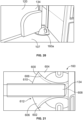
Figure 19 illustrates a perspective view of the exampleupper bearing 160b retaining an upper portion of theend 134 of thesecond panel 120.Figure 20 illustrates a perspective view of the examplelower bearing 160a retaining a lower portion of theend 134 of thesecond panel 120.Figure 21 illustrates a plan view of an example bearing 160 (such as thelower bearing 160a or theupper bearing 160b) retaining theend 134 of thesecond panel 120. Referring toFigures 19-21 , each bearing 160 may include a base 600 secured to a structure (such as thefloor 107 or the ceiling 109), and opposedprotuberances base 600. Theprotuberances protuberances walls 606 that outwardly curve away from acentral channel 608 toward afront end 610, thereby providing an expanded lead-inpassage 612 for thecentral channel 608. The expanded lead-inpassage 612 allows theend 134 to be pivoted into thecentral channel 608 and securely retained between theprotuberances central channel 608. - The bearings shown in
Figures 19-21 are merely examples, and other types of bearings can be used to securely retain theend 134. For example, spring-loaded retention balls can be used to snapably secure theend 134. As another example, strike fittings having pockets that receive a latching rod or bolt can be used. As another example, hooks can be used to secure theend 134 in a desired position. -
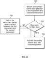
Figure 22 illustrates a flow chart of an example method. Referring toFigures 1 and22 , at 700, thesecondary barrier door 110 is secured between thefirst monument second monument flight deck 104 is desired. If so, the method proceeds from 702 to 704, at which thesecondary barrier door 110 is folded into the stowedposition 136. The method then returns to 702. If, at 702, an open path to the flight deck is not desired, but the path is to be closed, the method proceeds to 706, at which thesecondary barrier door 110 is unfolded to extend between thefirst monument second monument secondary barrier door 110 into the stowedposition 136 in which thepath 144 to theflight deck 104 is open, and unfolding the secondary barrier into the deployedposition 138 in which thepath 144 to theflight deck 104 is closed. In some examples, the method comprises receiving and retaining, by thelower bearing 160a and theupper bearing 160b, theend 134 of thesecond panel 120 when thesecondary barrier door 110 is in the deployedposition 138. The method may further comprise securing, by the lock of thepivot hinge 122, thesecondary barrier door 110 in a desired position. The method may further comprise allowing, by theoverride device 500 of thesecondary barrier door 110, thesecondary barrier door 110 to be removed. - Referring to
Figures 1-22 , examples provide asecondary barrier door 110 having foldable portions, such as thefirst panel 118 and thesecond panel 120 pivotally coupled together by thepivot hinge 122. Thesecondary barrier door 110 provides a bi-fold door. The foldablesecondary barrier door 110 allows for additional vestibule space due to a smaller sweep volume needed to move thesecondary barrier door 110 into the deployed position 138 (in contrast to a full sized slab door). - Further, the disclosure comprises embodiments according to the following clauses:
- Clause 1. An aircraft, comprising:
- a flight deck including a flight deck door configured to be moved between an open position and a closed position;
- a first monument;
- a second monument; and
- a secondary barrier door moveably secured between the first monument and the second monument, wherein the secondary barrier door is configured to fold into a stowed position in which a path to the flight deck is open, and unfold into a deployed position in which the path to the flight deck is closed.
- Clause 2. The aircraft of Clause 1, wherein the secondary barrier door comprises:
- a first panel;
- a second panel; and
- a pivot hinge pivotally coupling the first panel to the second panel.
- Clause 3. The aircraft of Clause 2, wherein the first panel is folded adjacent to the first monument, and the second panel is folded adjacent to the first panel when the secondary barrier door is in the stowed position.
- Clause 4. The aircraft of Clauses 2 or 3, wherein the first panel is pivotally coupled to a lower pivot bearing secured to a floor, and an upper pivot bearing secured to a ceiling.
- Clause 5. The aircraft of any of Clauses 2-4, further comprising a lower bearing and an upper bearing configured to receive and retain an end of the second panel when the secondary barrier door is in the deployed position.
- Clause 6. The aircraft of any of Clauses 2-5, wherein the pivot hinge comprises a lock configured to secure the secondary barrier door in a desired position.
- Clause 7. The aircraft of any of Clauses 1-6, wherein the secondary barrier door in the deployed position extends between the first monument and the second monument.
-
Clause 8. The aircraft of any of Clauses 1-7, wherein a closed security vestibule is defined between the flight deck, the first monument, the second monument, and the secondary barrier door in the deployed position. - Clause 9. The aircraft of any of Clauses 1-8, wherein the secondary barrier door is in front of a passenger seating area.
- Clause 10. The aircraft of any of Clauses 1-9, wherein the secondary barrier door comprises an override device configured to allow the secondary barrier door to be removed.
- Clause 11. A method for an aircraft comprising:
- a flight deck including a flight deck door configured to be moved between an open position and a closed position;
- a first monument;
- a second monument; and
- a secondary barrier door moveably secured between the first monument and the second monument, wherein the secondary barrier door is configured to fold into a stowed position in which a path to the flight deck is open, and unfold into a deployed position in which the path to the flight deck is closed,
- the method comprising:
- folding the secondary barrier door into the stowed position in which the path to the flight deck is open; and
- unfolding the secondary barrier into the deployed position in which the path to the flight deck is closed.
- Clause 12. The method of Clause 11, wherein the secondary barrier door comprises:
- a first panel;
- a second panel; and
- a pivot hinge pivotally coupling the first panel to the second panel.
- Clause 13. The method of Clause 12, wherein the first panel is folded adjacent to the first monument, and the second panel is folded adjacent to the first panel when the secondary barrier door is in the stowed position.
- Clause 14. The method of Clauses 12 or 13, wherein the first panel is pivotally coupled to a lower pivot bearing secured to a floor, and an upper pivot bearing secured to a ceiling.
- Clause 15. The method of any of Clauses 12-14, receiving and retaining, by a lower bearing and an upper bearing, an end of the second panel when the secondary barrier door is in the deployed position.
- Clause 16. The method of any of Clauses 12-15, further comprising securing, by a lock of the pivot hinge, the secondary barrier door in a desired position.
- Clause 17. The method of any of Clauses 11-16, wherein the secondary barrier door in the deployed position extends between the first monument and the second monument.
- Clause 18. The method of any of Clauses 11-17, wherein a closed security vestibule is defined between the flight deck, the first monument, the second monument, and the secondary barrier door in the deployed position.
- Clause 19. The method of any of Clauses 11-18, further comprising allowing, by an override device of the secondary barrier door, the secondary barrier door to be removed.
- Clause 20. An aircraft, comprising:
- a flight deck including a flight deck door configured to be moved between an open position and a closed position;
- a first monument;
- a second monument;
- a secondary barrier door in front of a passenger seating area, wherein the secondary barrier door is moveably secured between the first monument and the second monument, wherein the secondary barrier door is configured to fold into a stowed position in which a path to the flight deck is open, and unfold into a deployed position in which the path to the flight deck is closed, wherein the secondary barrier door in the deployed position extends between the first monument and the second monument, wherein a closed security vestibule is defined between the flight deck, the first monument, the second monument, and the secondary barrier door in the deployed position, and wherein the secondary barrier door comprises:
- a first panel;
- a second panel;
- a pivot hinge pivotally coupling the first panel to the second panel, wherein the first panel is folded adjacent to the first monument, and the second panel is folded adjacent to the first panel when the secondary barrier door is in the stowed position, wherein the first panel is pivotally coupled to a lower pivot bearing secured to a floor, and an upper pivot bearing secured to a ceiling, and wherein the pivot hinge comprises a lock configured to secure the secondary barrier door in a desired position; and
- an override device configured to allow the secondary barrier door to be removed; and
- a lower bearing and an upper bearing configured to receive and retain an end of the second panel when the secondary barrier door is in the deployed position.
- As described herein, examples of the present disclosure provide barrier systems and methods for preventing access to a flight deck during a door transition. Further, examples of the present disclosure provide efficient and effective systems and methods for providing a secondary barrier to a flight deck.
- While various spatial and directional terms, such as top, bottom, lower, mid, lateral, horizontal, vertical, front and the like can be used to describe embodiments of the present disclosure, it is understood that such terms are merely used with respect to the orientations shown in the drawings. The orientations can be inverted, rotated, or otherwise changed, such that an upper portion is a lower portion, aft may be changed to forward, and vice versa, horizontal becomes vertical, and the like.
- As used herein, a structure, limitation, or element that is "configured to" perform a task or operation is particularly structurally formed, constructed, or adapted in a manner corresponding to the task or operation. For purposes of clarity and the avoidance of doubt, an object that is merely capable of being modified to perform the task or operation is not "configured to" perform the task or operation as used herein.
- It is to be understood that the above description is intended to be illustrative, and not restrictive. For example, the above-described embodiments (and/or aspects thereof) can be used in combination with each other. In addition, many modifications can be made to adapt a particular situation or material to the teachings of the various embodiments of the disclosure without departing from their scope. While the dimensions and types of materials described herein are intended to define the parameters of the various embodiments of the disclosure, the embodiments are by no means limiting and are exemplary embodiments. Many other embodiments will be apparent to those of skill in the art upon reviewing the above description. The scope of the various embodiments of the disclosure should, therefore, be determined with reference to the appended claims, along with the full scope of equivalents to which such claims are entitled. In the appended claims and the detailed description herein, the terms "including" and "in which" are used as the plain-English equivalents of the respective terms "comprising" and "wherein." Moreover, the terms "first," "second," and "third," etc. are used merely as labels, and are not intended to impose numerical requirements on their objects. Further, the limitations of the following claims are not written in means-plus-function format and are not intended to be interpreted based on 35 U.S.C. § 112(f), unless and until such claim limitations expressly use the phrase "means for" followed by a statement of function void of further structure.
- This written description uses examples to disclose the various embodiments of the disclosure, including the best mode, and also to enable any person skilled in the art to practice the various embodiments of the disclosure, including making and using any devices or systems and performing any incorporated methods. The patentable scope of the various embodiments of the disclosure is defined by the claims, and can include other examples that occur to those skilled in the art. Such other examples are intended to be within the scope of the claims if the examples have structural elements that do not differ from the literal language of the claims, or if the examples include equivalent structural elements with insubstantial differences from the literal language of the claims.
Claims (15)
- An aircraft (102), comprising:a flight deck (104) including a flight deck door (106) configured to be moved between an open position and a closed position;a first monument (112, 114);a second monument (112, 114); anda secondary barrier door (110) moveably secured between the first monument (112, 114) and the second monument (112, 114), wherein the secondary barrier door (110) is configured to fold into a stowed position (136) in which a path (144) to the flight deck (104) is open, and unfold into a deployed position (138) in which the path (144) to the flight deck (104) is closed.
- The aircraft (102) of claim 1, wherein the secondary barrier door (110) comprises:a first panel (118);a second panel (120); anda pivot hinge (122) pivotally coupling the first panel (118) to the second panel (120).
- The aircraft (102) of claim 2, wherein the first panel (118) is folded adjacent to the first monument (112, 114), and the second panel (120) is folded adjacent to the first panel (118) when the secondary barrier door (110) is in the stowed position (136).
- The aircraft (102) of claim 2 or 3, wherein the first panel (118) is pivotally coupled to a lower pivot bearing (128a) secured to a floor (107), and an upper pivot bearing (128b) secured to a ceiling (109).
- The aircraft (102) of any one of claims 2 to 4, further comprising a lower bearing (160a) and an upper bearing (160b) configured to receive and retain an end (134) of the second panel (120) when the secondary barrier door (110) is in the deployed position (138).
- The aircraft (102) of any one of claims 2 to 5, wherein the pivot hinge (122) comprises a lock (125) configured to secure the secondary barrier door (110) in a desired position.
- The aircraft (102) of any one of claims 1 to 6, wherein the secondary barrier door (110) in the deployed position (138) extends between the first monument (112, 114) and the second monument (112, 114).
- The aircraft (102) of any one of claims 1 to 7, wherein a closed security vestibule (150) is defined between the flight deck (104), the first monument (112, 114), the second monument (112, 114), and the secondary barrier door (110) in the deployed position (138).
- The aircraft (102) of any one of claims 1 to 8, wherein the secondary barrier door (110) is in front of a passenger seating area (151).
- The aircraft (102) of any one of claims 1 to 9, wherein the secondary barrier door (110) comprises an override device (500) configured to allow the secondary barrier door (110) to be removed.
- A method for an aircraft (102) according to claim 1, the method comprising:folding the secondary barrier door (110) into the stowed position (136) in which the path (144) to the flight deck (104) is open; andunfolding the secondary barrier into the deployed position (138) in which the path (144) to the flight deck (104) is closed.
- The method of claim 11, wherein the secondary barrier door (110) comprises:a first panel (118);a second panel (120); anda pivot hinge (122) pivotally coupling the first panel (118) to the second panel (120).
- The method of claim 12, comprising receiving and retaining, by a lower bearing (160a) and an upper bearing (160b), an end (134) of the second panel (120) when the secondary barrier door (110) is in the deployed position (138).
- The method of claim 12 or 13, further comprising securing, by a lock (125) of the pivot hinge (122), the secondary barrier door (110) in a desired position.
- The method of any one of claims 11 to 14, further comprising allowing, by an override device (500) of the secondary barrier door (110), the secondary barrier door (110) to be removed.
Applications Claiming Priority (1)
| Application Number | Priority Date | Filing Date | Title |
|---|---|---|---|
| US18/405,260 US12434856B2 (en) | 2024-01-05 | 2024-01-05 | Bi-fold barrier system and method for a flight deck of an aircraft |
Publications (1)
| Publication Number | Publication Date |
|---|---|
| EP4582338A1 true EP4582338A1 (en) | 2025-07-09 |
Family
ID=93648672
Family Applications (1)
| Application Number | Title | Priority Date | Filing Date |
|---|---|---|---|
| EP24214847.6A Pending EP4582338A1 (en) | 2024-01-05 | 2024-11-22 | Bi-fold barrier system and method for a flight deck of an aircraft |
Country Status (3)
| Country | Link |
|---|---|
| US (1) | US12434856B2 (en) |
| EP (1) | EP4582338A1 (en) |
| CN (1) | CN120270477A (en) |
Families Citing this family (2)
| Publication number | Priority date | Publication date | Assignee | Title |
|---|---|---|---|---|
| US20250304235A1 (en) * | 2024-03-28 | 2025-10-02 | The Boeing Company | Door Assembly with an Engagement Assembly |
| US20250305325A1 (en) * | 2024-03-28 | 2025-10-02 | The Boeing Company | Barrier Door with Hinged Lock |
Citations (5)
| Publication number | Priority date | Publication date | Assignee | Title |
|---|---|---|---|---|
| US20160083092A1 (en) * | 2014-03-27 | 2016-03-24 | C&D Zodiac, Inc. | Bi-fold door module |
| US20210291955A1 (en) * | 2020-03-17 | 2021-09-23 | The Boeing Company | Movable barrier with pressure equalization features |
| US20220355949A1 (en) * | 2019-06-25 | 2022-11-10 | Schroth Safety Products Gmbh | Device for preventing access to an area of an aircraft |
| US20230083772A1 (en) * | 2021-09-10 | 2023-03-16 | Harper Engineering Co. | Bi-fold door |
| EP4477530A1 (en) * | 2023-06-16 | 2024-12-18 | The Boeing Company | Dual purpose lavatory barrier |
Family Cites Families (14)
| Publication number | Priority date | Publication date | Assignee | Title |
|---|---|---|---|---|
| US1876881A (en) * | 1931-11-04 | 1932-09-13 | William H Durant | Doorstop |
| US20030047648A1 (en) * | 2001-09-12 | 2003-03-13 | Batt Richard R. | Secure cockpit system |
| US20030052227A1 (en) * | 2001-09-17 | 2003-03-20 | Pittman Donald Merve | Protective shield for aircraft cockpit crew |
| US20040149858A1 (en) * | 2002-07-16 | 2004-08-05 | Warren Marshall | Airplane security system |
| US6659401B1 (en) * | 2002-11-13 | 2003-12-09 | Robert M. Semprini | Airplane door lock system |
| US20060000946A1 (en) * | 2004-05-18 | 2006-01-05 | Primo Garofani | Secondary barrier system |
| US7984875B2 (en) * | 2007-09-11 | 2011-07-26 | The Boeing Company | Multi-position secure door system |
| US9518421B2 (en) * | 2013-04-22 | 2016-12-13 | National School Control Systems, LLC | Safety door barricade |
| US9439526B2 (en) * | 2014-04-10 | 2016-09-13 | Textron Innovations, Inc. | System for attachment of coat rod and cargo net |
| FR3036098B1 (en) * | 2015-05-12 | 2017-05-12 | Airbus Operations Sas | FOLDING WALL ACCESS DEVICE FOR SECURE COMMUNICATION BETWEEN AT LEAST TWO ZONES OF AN ENCLOSURE |
| US11279461B2 (en) | 2017-06-01 | 2022-03-22 | The Boeing Company | Flight deck barrier door, aircraft comprising flight deck barrier door, and method of using flight deck barrier door |
| US10766596B2 (en) * | 2018-02-08 | 2020-09-08 | The Boeing Company | Aircraft privacy door and door frame assembly |
| EP4388166A4 (en) * | 2021-08-16 | 2025-11-19 | Harper Eng Co | FLIGHT DECK BARRIER DEVICE |
| US12084164B2 (en) * | 2022-10-17 | 2024-09-10 | The Boeing Company | Privacy door for an internal cabin of a vehicle |
-
2024
- 2024-01-05 US US18/405,260 patent/US12434856B2/en active Active
- 2024-11-22 EP EP24214847.6A patent/EP4582338A1/en active Pending
- 2024-12-10 CN CN202411805494.0A patent/CN120270477A/en active Pending
Patent Citations (5)
| Publication number | Priority date | Publication date | Assignee | Title |
|---|---|---|---|---|
| US20160083092A1 (en) * | 2014-03-27 | 2016-03-24 | C&D Zodiac, Inc. | Bi-fold door module |
| US20220355949A1 (en) * | 2019-06-25 | 2022-11-10 | Schroth Safety Products Gmbh | Device for preventing access to an area of an aircraft |
| US20210291955A1 (en) * | 2020-03-17 | 2021-09-23 | The Boeing Company | Movable barrier with pressure equalization features |
| US20230083772A1 (en) * | 2021-09-10 | 2023-03-16 | Harper Engineering Co. | Bi-fold door |
| EP4477530A1 (en) * | 2023-06-16 | 2024-12-18 | The Boeing Company | Dual purpose lavatory barrier |
Also Published As
| Publication number | Publication date |
|---|---|
| US12434856B2 (en) | 2025-10-07 |
| US20250223053A1 (en) | 2025-07-10 |
| CN120270477A (en) | 2025-07-08 |
Similar Documents
| Publication | Publication Date | Title |
|---|---|---|
| US11851186B2 (en) | Mini suite emergency egress solutions | |
| US12434856B2 (en) | Bi-fold barrier system and method for a flight deck of an aircraft | |
| US8672267B2 (en) | Toilet arrangement for a vehicle | |
| US20140360099A1 (en) | Lavatory Reconfiguration System | |
| US12515782B2 (en) | Privacy door for an internal cabin of a vehicle | |
| US10737788B2 (en) | Systems and methods for adaptively positioning a cross-aisle curtain header assembly within a vehicle | |
| US11884401B2 (en) | Lavatory systems having containment compartments | |
| EP4098564B1 (en) | Resting area systems for an internal cabin of a vehicle | |
| US12522358B1 (en) | Convertible lavatory system for an internal cabin of an aircraft | |
| US10259586B2 (en) | Deployable seat assembly, system, and method for an interior cabin of a vehicle | |
| EP4461647A1 (en) | Wheelchair accessible airliner lavatory | |
| US12617532B2 (en) | Dual purpose lavatory barrier | |
| US20250128815A1 (en) | Barrier system and method for a flight deck of an aircraft | |
| US12168515B2 (en) | Lavatory systems having adjacent lavatory units within an internal cabin of a vehicle | |
| US11945588B2 (en) | Stowage bin assemblies for and a method for increasing overhead space and configurability in an internal cabin of a vehicle | |
| US20250108905A1 (en) | Barrier Door with Stowage Frame | |
| EP4733191A1 (en) | Convertible lavatory system for an internal cabin of an aircraft | |
| US20240351690A1 (en) | Lounge system for an internal cabin of an aircraft | |
| US12559237B2 (en) | Combination monument having lavatory and galley for an internal cabin of an aircraft | |
| EP4624320A1 (en) | Door assembly with an engagement mechanism | |
| EP4455007A1 (en) | Crew rest system for an internal cabin of an aircraft | |
| BR102023017013A2 (en) | PRIVACY DOOR FOR AN INTERNAL CABIN OF A VEHICLE |
Legal Events
| Date | Code | Title | Description |
|---|---|---|---|
| PUAI | Public reference made under article 153(3) epc to a published international application that has entered the european phase |
Free format text: ORIGINAL CODE: 0009012 |
|
| STAA | Information on the status of an ep patent application or granted ep patent |
Free format text: STATUS: THE APPLICATION HAS BEEN PUBLISHED |
|
| AK | Designated contracting states |
Kind code of ref document: A1 Designated state(s): AL AT BE BG CH CY CZ DE DK EE ES FI FR GB GR HR HU IE IS IT LI LT LU LV MC ME MK MT NL NO PL PT RO RS SE SI SK SM TR |
|
| STAA | Information on the status of an ep patent application or granted ep patent |
Free format text: STATUS: REQUEST FOR EXAMINATION WAS MADE |
|
| 17P | Request for examination filed |
Effective date: 20260107 |
|
| GRAP | Despatch of communication of intention to grant a patent |
Free format text: ORIGINAL CODE: EPIDOSNIGR1 |
|
| STAA | Information on the status of an ep patent application or granted ep patent |
Free format text: STATUS: GRANT OF PATENT IS INTENDED |
|
| RIC1 | Information provided on ipc code assigned before grant |
Ipc: B64C 1/14 20060101AFI20260612BHEP Ipc: B64D 11/00 20060101ALI20260612BHEP Ipc: B64D 45/00 20060101ALI20260612BHEP |
|
| INTG | Intention to grant announced |
Effective date: 20260707 |