EP4582330A1 - Steering device - Google Patents
Steering device Download PDFInfo
- Publication number
- EP4582330A1 EP4582330A1 EP22957316.7A EP22957316A EP4582330A1 EP 4582330 A1 EP4582330 A1 EP 4582330A1 EP 22957316 A EP22957316 A EP 22957316A EP 4582330 A1 EP4582330 A1 EP 4582330A1
- Authority
- EP
- European Patent Office
- Prior art keywords
- shaft
- bearing
- ball screw
- housing
- axial direction
- Prior art date
- Legal status (The legal status is an assumption and is not a legal conclusion. Google has not performed a legal analysis and makes no representation as to the accuracy of the status listed.)
- Pending
Links
Images


Classifications
-
- B—PERFORMING OPERATIONS; TRANSPORTING
- B62—LAND VEHICLES FOR TRAVELLING OTHERWISE THAN ON RAILS
- B62D—MOTOR VEHICLES; TRAILERS
- B62D3/00—Steering gears
- B62D3/02—Steering gears mechanical
- B62D3/04—Steering gears mechanical of worm type
- B62D3/06—Steering gears mechanical of worm type with screw and nut
- B62D3/08—Steering gears mechanical of worm type with screw and nut using intermediate balls or the like
-
- B—PERFORMING OPERATIONS; TRANSPORTING
- B62—LAND VEHICLES FOR TRAVELLING OTHERWISE THAN ON RAILS
- B62D—MOTOR VEHICLES; TRAILERS
- B62D5/00—Power-assisted or power-driven steering
- B62D5/04—Power-assisted or power-driven steering electrical, e.g. using an electric servo-motor connected to, or forming part of, the steering gear
- B62D5/0403—Power-assisted or power-driven steering electrical, e.g. using an electric servo-motor connected to, or forming part of, the steering gear characterised by constructional features, e.g. common housing for motor and gear box
-
- B—PERFORMING OPERATIONS; TRANSPORTING
- B62—LAND VEHICLES FOR TRAVELLING OTHERWISE THAN ON RAILS
- B62D—MOTOR VEHICLES; TRAILERS
- B62D5/00—Power-assisted or power-driven steering
- B62D5/04—Power-assisted or power-driven steering electrical, e.g. using an electric servo-motor connected to, or forming part of, the steering gear
- B62D5/0421—Electric motor acting on or near steering gear
Definitions
- the present disclosure relates to a steering system.
- cab-over vehicles such as freight vehicles in which a driver's seat is located forward of a front wheel axle often use an axle suspension in which right and left wheels are connected by an axle.
- the vehicles including the axle suspension often use a ball screw steering gearbox.
- the steering gearbox is mounted on, for example, a vehicle body frame.
- An electric power steering system of Patent Document 1 includes a motor and a ball screw steering gearbox.
- the steering gearbox converts a rotational motion of a steering shaft into rotation of an output shaft that rotates in conjunction with steered wheels.
- the direction of the steered wheels is changed in conjunction with the rotation of the output shaft.
- the torque of the motor is transmitted to a ball screw shaft of the steering gearbox via a worm reducer. This assists steering of a steering wheel.
- the steering shaft includes an input shaft, an output shaft, and a torsion bar.
- the input shaft and the output shaft are connected to each other via the torsion bar.
- Steering torque applied to the steering wheel is transmitted to the output shaft via the input shaft and the torsion bar.
- the torsion bar is twisted in response to the steering torque.
- the end of the output shaft opposite to the input shaft is connected to the end of the ball screw shaft.
- Patent Document 1 Chinese Patent Application Publication No. 111284556
- the electric power steering system of Patent Document 1 has the following concern. That is, the output shaft and the ball screw shaft are coupled to each other by serration coupling.
- the serration coupling is a method of coupling a rotation shaft to a component having a fitting portion to which the rotation shaft is fitted. Serrated teeth provided on the outer circumferential surface of the rotation shaft and serrated grooves provided on the inner circumferential surface of the fitting portion are fitted together to restrict relative rotation between the rotation shaft and the component.
- serrated teeth extending in an axial direction are provided on the outer circumferential surface of the end of the output shaft coupled to the ball screw shaft.
- the end of the ball screw shaft to which the output shaft is coupled includes a fitting portion.
- Serrated grooves extending in the axial direction are provided on the inner circumferential surface of the fitting portion. The serrated teeth and the serrated grooves are fitted together by press-fitting the end of the output shaft to the fitting portion.
- a steering system includes a shaft configured to rotate in conjunction with steering of a steering wheel of a vehicle, a ball screw mechanism configured to convert rotation of the shaft into rotation of an output shaft configured to operate in conjunction with a steered wheel, and a speed reducer configured to apply torque to the shaft.
- the ball screw mechanism includes a first housing, a ball screw shaft housed inside the first housing, the ball screw shaft including a first end and a second end, and being connected to the shaft to be rotatable together by intermeshing coupling between the first end and the shaft, a first bearing that supports the first end of the ball screw shaft so that the ball screw shaft is rotatable relative to the first housing, and a second bearing that supports the second end of the ball screw shaft so that the ball screw shaft is rotatable relative to the first housing.
- the speed reducer includes a second housing that is connected to the first housing in an axial direction and into which the shaft is inserted in the axial direction, and a third bearing that supports the shaft so that the shaft is rotatable relative to the second housing.
- a line passing through a center of a cross section obtained by cutting the first bearing in the axial direction and parallel to a central axis of the shaft is a first center line.
- a line passing through a center of a cross section obtained by cutting the second bearing in the axial direction and parallel to the central axis of the shaft is a second center line.
- a line passing through a center of a cross section obtained by cutting the third bearing in the axial direction and parallel to the central axis of the shaft is a third center line.
- An outside diameter of the shaft is set so that the third center line is positioned on an outer side of the first center line or the second center line in a radial direction about the central axis of the shaft.
- the steering system is, for example, an electric power steering system.
Landscapes
- Engineering & Computer Science (AREA)
- Chemical & Material Sciences (AREA)
- Combustion & Propulsion (AREA)
- Transportation (AREA)
- Mechanical Engineering (AREA)
- Power Steering Mechanism (AREA)
Abstract
Description
- The present disclosure relates to a steering system.
- Hitherto, so-called cab-over vehicles such as freight vehicles in which a driver's seat is located forward of a front wheel axle often use an axle suspension in which right and left wheels are connected by an axle. The vehicles including the axle suspension often use a ball screw steering gearbox. The steering gearbox is mounted on, for example, a vehicle body frame.
- An electric power steering system of
Patent Document 1 includes a motor and a ball screw steering gearbox. The steering gearbox converts a rotational motion of a steering shaft into rotation of an output shaft that rotates in conjunction with steered wheels. The direction of the steered wheels is changed in conjunction with the rotation of the output shaft. The torque of the motor is transmitted to a ball screw shaft of the steering gearbox via a worm reducer. This assists steering of a steering wheel. - The steering shaft includes an input shaft, an output shaft, and a torsion bar. The input shaft and the output shaft are connected to each other via the torsion bar. Steering torque applied to the steering wheel is transmitted to the output shaft via the input shaft and the torsion bar. The torsion bar is twisted in response to the steering torque. The end of the output shaft opposite to the input shaft is connected to the end of the ball screw shaft.
- Patent Document 1:
Chinese Patent Application Publication No. 111284556 - Problem to be Solved by the Invention
- The electric power steering system of
Patent Document 1 has the following concern. That is, the output shaft and the ball screw shaft are coupled to each other by serration coupling. The serration coupling is a method of coupling a rotation shaft to a component having a fitting portion to which the rotation shaft is fitted. Serrated teeth provided on the outer circumferential surface of the rotation shaft and serrated grooves provided on the inner circumferential surface of the fitting portion are fitted together to restrict relative rotation between the rotation shaft and the component. - In the electric power steering system of
Patent Document 1, serrated teeth extending in an axial direction are provided on the outer circumferential surface of the end of the output shaft coupled to the ball screw shaft. The end of the ball screw shaft to which the output shaft is coupled includes a fitting portion. Serrated grooves extending in the axial direction are provided on the inner circumferential surface of the fitting portion. The serrated teeth and the serrated grooves are fitted together by press-fitting the end of the output shaft to the fitting portion. - However, there is a slight amount of backlash between the end of the output shaft and the fitting portion of the ball screw shaft in a rotation direction or a radial direction thereof. Along with long-term use of the electric power steering system, the amount of backlash between the end of the output shaft and the fitting portion of the ball screw shaft may gradually increase. In this case, there is a concern that the output shaft may tilt due to the backlash between the end of the output shaft and the fitting portion of the ball screw shaft.
- A steering system according to one embodiment of the present disclosure includes a shaft configured to rotate in conjunction with steering of a steering wheel of a vehicle, a ball screw mechanism configured to convert rotation of the shaft into rotation of an output shaft configured to operate in conjunction with a steered wheel, and a speed reducer configured to apply torque to the shaft. The ball screw mechanism includes a first housing, a ball screw shaft housed inside the first housing, the ball screw shaft including a first end and a second end, and being connected to the shaft to be rotatable together by intermeshing coupling between the first end and the shaft, a first bearing that supports the first end of the ball screw shaft so that the ball screw shaft is rotatable relative to the first housing, and a second bearing that supports the second end of the ball screw shaft so that the ball screw shaft is rotatable relative to the first housing. The speed reducer includes a second housing that is connected to the first housing in an axial direction and into which the shaft is inserted in the axial direction, and a third bearing that supports the shaft so that the shaft is rotatable relative to the second housing. A line passing through a center of a cross section obtained by cutting the first bearing in the axial direction and parallel to a central axis of the shaft is a first center line. A line passing through a center of a cross section obtained by cutting the second bearing in the axial direction and parallel to the central axis of the shaft is a second center line. A line passing through a center of a cross section obtained by cutting the third bearing in the axial direction and parallel to the central axis of the shaft is a third center line. An outside diameter of the shaft is set so that the third center line is positioned on an outer side of the first center line or the second center line in a radial direction about the central axis of the shaft.
-
- [
FIG. 1] FIG. 1 is a schematic diagram of a steering system according to one embodiment. - [
FIG. 2] FIG. 2 is a sectional view of a steering gearbox inFIG. 1 . - [
FIG. 3A] FIG. 3A is a sectional view showing a first comparative example of an output shaft inFIG. 2 . - [
FIG. 3B] FIG. 3B is a sectional view showing a second comparative example of the output shaft inFIG. 2 . - [
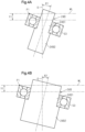
FIG. 4A] FIG. 4A is a sectional view showing tilt in the first comparative example of the output shaft inFIG. 2 . - [
FIG. 4B] FIG. 4B is a sectional view showing tilt in the second comparative example of the output shaft inFIG. 2 . - A steering system according to one embodiment will be described. The steering system is, for example, an electric power steering system.
- As shown in
FIG. 1 , asteering system 20 is mounted on, for example, a cab-overvehicle 10. Thevehicle 10 includes anaxle suspension 11. Thesuspension 11 supports afront axle 12. Steeredwheels 13 that are front wheels are connected to both ends of thefront axle 12. Thesuspension 11 includes aleaf spring 14. As an example, theleaf spring 14 is positioned above thefront axle 12. Theleaf spring 14 extends in a front-rear direction of the vehicle. Both ends of theleaf spring 14 are attached to avehicle body frame 16 viasupport members 15 such as shackles. - The
steering system 20 includes a steeringshaft 21, asteering gearbox 22, amotor 23, atorque sensor 24, and aspeed reducer 25. The steeringshaft 21 and thesteering gearbox 22 constitute a steering mechanism of thevehicle 10. A first end of the steeringshaft 21 is connected to asteering wheel 26. A second end of the steeringshaft 21 is connected to thesteering gearbox 22 via thetorque sensor 24 and thespeed reducer 25. Themotor 23 is connected to thesteering gearbox 22 via thespeed reducer 25. The steeringgearbox 22 is, for example, of an RBS type (recirculating ball screw type). - The steering
gearbox 22 is connected to the steeredwheels 13 via alink mechanism 30. Thelink mechanism 30 includes apitman arm 31, adrag link 32, and atie rod 33. The base end of thepitman arm 31 is connected to the side of thesteering gearbox 22. Thepitman arm 31 is swingable about its base end in the front-rear direction of the vehicle. A first end of thedrag link 32 is rotatably connected to the distal end of thepitman arm 31. A second end of thedrag link 32 is rotatably connected to aknuckle arm 34 of the right steeredwheel 13. Both ends of thetie rod 33 are connected to the right and left steeredwheels 13 viatie rod arms 35. - The rotation of the
steering wheel 26 is transmitted to thesteering gearbox 22 via the steeringshaft 21. The steeringgearbox 22 converts a rotational motion of the steeringshaft 21 into a swinging motion of thepitman arm 31. The swinging motion of thepitman arm 31 drives thedrag link 32 in the front-rear direction of the vehicle. Theknuckle arm 34 swings in conjunction with thedrag link 32, thereby turning the steeredwheels 13. - The
motor 23 generates torque in the same direction as the steering direction of thesteering wheel 26 in response to steering torque detected by thetorque sensor 24. The torque of themotor 23 is transmitted to the steeringshaft 21 via thespeed reducer 25. That is, thespeed reducer 25 is configured to apply torque to the steeringshaft 21. The torque in the same direction as the steering direction is applied to the steeringshaft 21, thereby assisting the steering of thesteering wheel 26. - As shown in
FIG. 2 , the steeringgearbox 22 includes afirst housing 40. Aball screw shaft 41, aball screw nut 42, a plurality ofballs 43, asector shaft 44, and asector gear 45 are provided inside thefirst housing 40. - When the
steering gearbox 22 is mounted on thevehicle 10, theball screw shaft 41 is maintained in a posture in which it extends in the vertical direction with respect to thevehicle 10. The ball screwshaft 41 is supported via afirst bearing 46 and asecond bearing 47 to be rotatable relative to thefirst housing 40. Thefirst bearing 46 and thesecond bearing 47 are, for example, the same products. - The
first bearing 46 supports a first end of theball screw shaft 41. The first end is an end of theball screw shaft 41 oriented upward of thevehicle 10 when thesteering gearbox 22 is mounted on thevehicle 10. The first end of theball screw shaft 41 is connected to the steeringshaft 21 via thetorque sensor 24. - The
second bearing 47 supports a second end of theball screw shaft 41. The second end is an end of theball screw shaft 41 opposite to the first end. That is, the second end is an end of theball screw shaft 41 oriented downward of thevehicle 10 when thesteering gearbox 22 is mounted on thevehicle 10. The second end faces an end wall of thefirst housing 40. - The ball screw
shaft 41 has afirst groove 41A. Thefirst groove 41A is a helical groove provided on the outer circumferential surface of theball screw shaft 41. A threaded portion is formed by providing thefirst groove 41A. The ball screwshaft 41 has aconnection hole 41B at the first end. Theconnection hole 41B extends in an axial direction. A plurality of serration grooves extending in the axial direction is provided on the inner circumferential surface of theconnection hole 41B. The serration grooves are disposed at equal intervals in a circumferential direction of theconnection hole 41B. The serration groove has, for example, a triangular shape as viewed in the axial direction. - The ball screw
nut 42 has a tubular shape and has asecond groove 42A. Thesecond groove 42A is a helical groove provided on the inner circumferential surface of theball screw nut 42. Thesecond groove 42A faces thefirst groove 41A in a radial direction. The ball screwnut 42 engages with theball screw shaft 41 via the plurality ofballs 43. A helical space surrounded by thefirst groove 41A and thesecond groove 42A functions as a rolling path along which theballs 43 roll. The ball screwshaft 41, theball screw nut 42, and theballs 43 constitute aball screw mechanism 48. - The ball screw
nut 42 includes a plurality ofrack teeth 42B. Therack teeth 42B are provided on the outer circumferential surface of theball screw nut 42. Therack teeth 42B are arranged in an axial direction of theball screw nut 42. - The
sector shaft 44 extends in a direction orthogonal to the axis of the ball screw nut 42 (direction orthogonal to the drawing sheet ofFIG. 2 ). Thesector shaft 44 is supported via a bearing that is not shown to be rotatable relative to thefirst housing 40. Thesector shaft 44 has an outer end exposed to the outside through thefirst housing 40. The base end of thepitman arm 31 is fixed to the outer end of thesector shaft 44. Thesector shaft 44 is an output shaft of thesteering gearbox 22 and operates in conjunction with the steeredwheels 13. - The
sector gear 45 is provided to thesector shaft 44 to be rotatable together. Thesector gear 45 is a gear having a sector shape and has a plurality ofteeth 45A. Theteeth 45A of thesector gear 45 mesh with therack teeth 42B of theball screw nut 42. - The rotation of the
steering wheel 26 is transmitted to theball screw shaft 41 via the steeringshaft 21 and thetorque sensor 24. As theball screw shaft 41 rotates, theball screw nut 42 moves in the axial direction relative to theball screw shaft 41. Therefore, thesector gear 45 swings about thesector shaft 44. When thesector shaft 44 rotates as thesector gear 45 swings, thepitman arm 31 swings about thesector shaft 44. - As shown in
FIG. 2 , thetorque sensor 24 includes aninput shaft 24A, anoutput shaft 24B, atorsion bar 24C, and adetector 24D. Theinput shaft 24A and theoutput shaft 24B are connected to each other via thetorsion bar 24C. Theinput shaft 24A and theoutput shaft 24B are each a hollow cylinder. - A first end of the
input shaft 24A is connected to the steeringshaft 21. A second end of theinput shaft 24A is inserted into a first end of theoutput shaft 24B. Theinput shaft 24A is kept out of contact with theoutput shaft 24B. A plain bearing 24E is interposed between the outer circumferential surface of theinput shaft 24A and the inner circumferential surface of theoutput shaft 24B. Theinput shaft 24A and theoutput shaft 24B can rotate relative to each other via the plain bearing 24E. - A second end of the
output shaft 24B is fitted to theconnection hole 41B through an end wall of thefirst housing 40. A plurality of serration teeth extending in the axial direction is provided on the outer circumferential surface of the second end of theoutput shaft 24B. The serration teeth are disposed at equal intervals in the circumferential direction. The serration tooth has, for example, a triangular shape as viewed in the axial direction. The serration teeth of theoutput shaft 24B and the serration grooves of theconnection hole 41B are fitted together. Serration coupling between theoutput shaft 24B and theball screw shaft 41 restricts relative rotation between theoutput shaft 24B and theball screw shaft 41. Theoutput shaft 24B is rotatable together with theball screw shaft 41. - Although the coupling structure using so-called triangular tooth serrations has been exemplified, any structure may be used as long as it is intermeshing coupling between an inner member with external teeth and an outer member with internal teeth, and it may also be square splines or involute splines.
- The second end of the
output shaft 24B is an end of theoutput shaft 24B positioned opposite to a bearing attachment portion 24B1 across a worm wheel attachment portion 24B2. The second end of theoutput shaft 24B is indirectly supported by thefirst bearing 46 via a peripheral wall of theconnection hole 41B while being fitted to theconnection hole 41B in the axial direction. - The
output shaft 24B includes the bearing attachment portion 24B1 and the worm wheel attachment portion 24B2. The bearing attachment portion 24B1 and the worm wheel attachment portion 24B2 are positioned between the first end and the second end of theoutput shaft 24B. The outside diameter of the bearing attachment portion 24B1 is larger than the outside diameters of the other portions of theoutput shaft 24B except for the worm wheel attachment portion 24B2. The outside diameter of the worm wheel attachment portion 24B2 is slightly larger than the outside diameter of the bearing attachment portion 24B1. - The bearing attachment portion 24B1 and the worm wheel attachment portion 24B2 are adjacent to each other in the axial direction. The bearing attachment portion 24B1 is positioned opposite to the
ball screw shaft 41 across the worm wheel attachment portion 24B2. The bearing attachment portion 24B1 is a portion of theoutput shaft 24B positioned above the worm wheel attachment portion 24B2 when thesteering gearbox 22 is mounted on thevehicle 10. The worm wheel attachment portion 24B2 is a portion of theoutput shaft 24B positioned below the bearing attachment portion 24B1 when thesteering gearbox 22 is mounted on thevehicle 10. - The
torsion bar 24C is inserted into theinput shaft 24A and theoutput shaft 24B. A first end of thetorsion bar 24C is fixed to the inner circumferential surface of the first end of theinput shaft 24A. A second end of thetorsion bar 24C is fixed to the inner circumferential surface of the second end of theoutput shaft 24B. A clearance is present between the inner circumferential surface of theoutput shaft 24B and the outer circumferential surface of a portion of thetorsion bar 24C between the first end and the second end. - Steering torque applied to the
steering wheel 26 is transmitted to theinput shaft 24A via the steeringshaft 21. Therefore, theinput shaft 24A rotates. The rotation of theinput shaft 24A is transmitted to theoutput shaft 24B via thetorsion bar 24C. Therefore, theoutput shaft 24B rotates. Theoutput shaft 24B corresponds to a shaft that rotates in conjunction with the steering of thesteering wheel 26. Thetorsion bar 24C is twisted in response to the steering torque. - The
detector 24D is provided, for example, to surround the outer circumferential surface of theinput shaft 24A. Thedetector 24D detects steering torque based on the amount of twist of thetorsion bar 24C. - As shown in
FIG. 2 , thespeed reducer 25 includes asecond housing 50. Thesecond housing 50 is connected to thefirst housing 40 of thesteering gearbox 22. Thesecond housing 50 is connected to a portion of thefirst housing 40 that is closer to thefirst bearing 46 than to thesecond bearing 47 in the axial direction. - The
first housing 40 includes atubular connection portion 40A extending in the axial direction. Theconnection portion 40A is provided at the end of thefirst housing 40 oriented upward of thevehicle 10 when thesteering gearbox 22 is mounted on thevehicle 10. Theconnection portion 40A is closer to thefirst bearing 46 than to thesecond bearing 47 in the axial direction. - The
second housing 50 has a tubular shape and includes an end wall at a first end in the axial direction. The first end is an end of thesecond housing 50 oriented upward of thevehicle 10 when thesteering gearbox 22 is mounted on thevehicle 10. The end wall has afirst opening 50A. Theinput shaft 24A and theoutput shaft 24B extend through thefirst opening 50A in the axial direction in a non-contact state. Thesecond housing 50 has asecond opening 50B at a second end opposite to the first end. The second end is an end of thesecond housing 50 oriented downward of thevehicle 10 when thesteering gearbox 22 is mounted on thevehicle 10. - The
connection portion 40A of thefirst housing 40 and thesecond opening 50B of thesecond housing 50 are fitted together in the axial direction. Specifically, the inner circumferential surface of thesecond opening 50B is fitted to the outer circumferential surface of theconnection portion 40A. There is no step between the outer circumferential surface of thefirst housing 40 and the outer circumferential surface of thesecond housing 50. The inside of thefirst housing 40 and the inside of thesecond housing 50 communicate with each other. - The
motor 23 is attached to the outside of thesecond housing 50. Anoutput shaft 23A of themotor 23 extends, for example, in a direction orthogonal to the axis of theball screw shaft 41 and parallel to the axis of thesector shaft 44. Theoutput shaft 23A extends through thesecond housing 50 and is inserted into thesecond housing 50. - A
worm wheel 51 and aworm 52 are housed inside thesecond housing 50. Theoutput shaft 24B extends through thesecond housing 50 in the axial direction. - The
output shaft 24B is supported via athird bearing 53 to be rotatable relative to the inner circumferential surface of thefirst opening 50A of thesecond housing 50. Thethird bearing 53 is attached to the outer circumferential surface of the bearing attachment portion 24B1 of theoutput shaft 24B. Thethird bearing 53 is, for example, a ball bearing. The fitting between an inner ring of thethird bearing 53 and the outer circumferential surface of the bearing attachment portion 24B1 is clearance fit. That is, the bore diameter of the inner ring of thethird bearing 53 is slightly larger than the outside diameter of the bearing attachment portion 24B1. The fitting between an outer ring of thethird bearing 53 and the inner circumferential surface of thefirst opening 50A is clearance fit. That is, the outside diameter of the outer ring of thethird bearing 53 is slightly smaller than the bore diameter of thefirst opening 50A. - The
worm wheel 51 has a tubular shape and is attached to the outer circumferential surface of the worm wheel attachment portion 24B2 of theoutput shaft 24B. Theworm wheel 51 is rotatable together with theoutput shaft 24B. The first end face of theworm wheel 51 and thethird bearing 53 are spaced away from each other in the axial direction. The second end face of theworm wheel 51 and theconnection portion 40A of thefirst housing 40 are spaced away from each other in the axial direction. The second end face is an end face of theworm wheel 51 opposite to the first end face. The second end face of theworm wheel 51 has arecess 51A. Therecess 51A has, for example, a truncated cone shape. Therecess 51A is a region including the center of the second end face as viewed in the axial direction, and is provided in a region from the center of the second end face to the vicinity of the root. Therecess 51A is open opposite to the bearing attachment portion 24B1 across the worm wheel attachment portion 24B2. A portion of theconnection portion 40A of thefirst housing 40 is inserted into therecess 51A. - The
worm 52 is connected to theoutput shaft 23A of themotor 23 to be rotatable together. The axis of theoutput shaft 23A and the axis of theworm 52 coincide with each other. Theworm 52 meshes with theworm wheel 51. The shaft angle between theworm 52 and theworm wheel 51 is, for example, 90°. - The torque of the
motor 23 is transmitted to theball screw shaft 41 via thespeed reducer 25. The torque in the same direction as the steering direction of thesteering wheel 26 is applied to theball screw shaft 41, thereby assisting the steering of thesteering wheel 26. - As described above, the
output shaft 24B and theball screw shaft 41 are coupled to each other in the axial direction via the serration teeth and the serration grooves. In this case, there is a slight amount of backlash between theoutput shaft 24B and theball screw shaft 41 in a rotation direction or a radial direction thereof due to the structure. Further, the fitting between the outer ring of thethird bearing 53 and thefirst opening 50A is clearance fit. Therefore, there is a concern that theoutput shaft 24B may tilt about a fulcrum that is the connection point to theball screw shaft 41 depending on the clearance between the outer circumferential surface of the outer ring of thethird bearing 53 and the inner circumferential surface of thefirst opening 50A. - In the present embodiment, the following configuration is adopted to suppress the tilt of the
output shaft 24B. - As shown in
FIG. 2 , a line passing through the center of a cross section obtained by cutting thefirst bearing 46 in the axial direction and parallel to a central axis O of theoutput shaft 24B is a first center line O1. A line passing through the center of a cross section obtained by cutting thesecond bearing 47 in the axial direction and parallel to the central axis O of theoutput shaft 24B is a second center line O2. A line passing through the center of a cross section obtained by cutting thethird bearing 53 in the axial direction and parallel to the central axis O of theoutput shaft 24B is a third center line O3. An outside diameter φ1 of the bearing attachment portion 24B1 of theoutput shaft 24B is set so that the third center line O3 is positioned on an outer side of the first center line O1 in the radial direction about the central axis O of theoutput shaft 24B. In other words, the outside diameter φ1 of the bearing attachment portion 24B1 of theoutput shaft 24B is set so that a radial distance from the central axis O of theoutput shaft 24B to the third center line O3 is larger than a radial distance from the central axis O of theoutput shaft 24B to the first center line O1. In the following description, a "radially outer side" and a "radially inner side" mean an outer side and an inner side in the radial direction about the central axis O of theoutput shaft 24B, respectively. - With this configuration, the tilt of the
output shaft 24B can be suppressed compared to, for example, the case where the outside diameter φ1 of the bearing attachment portion 24B1 of theoutput shaft 24B is set so that the third center line O3 is positioned on the radially inner side of the first center line O1. This is because the tilt amount of theoutput shaft 24B decreases as the outside diameter φ1 of the bearing attachment portion 24B1 increases. - Although all the
first bearing 46, thesecond bearing 47, and thethird bearing 53 are ball bearings, thethird bearing 53 has a smaller ball diameter than theother bearings third bearing 53 can be increased, and the outside diameter φ1 of the bearing attachment portion 24B1 can further be increased. - The third center line O3 is positioned on the radially outer side of the second center line O2. The
first bearing 46 and thesecond bearing 47 are the same products and are positioned coaxially. Therefore, the second center line O2 coincides with the first center line O1. Thus, when the third center line O3 is positioned on the radially outer side of the first center line O1, the third center line O3 is naturally positioned on the radially outer side of the second center line O2. - The outside diameter φ1 of the bearing attachment portion 24B1 is larger than an outside diameter φ2 of the
ball screw shaft 41. The outside diameter φ2 is an outside diameter of a portion of theball screw shaft 41 other than the portions supported by thefirst bearing 46 and thesecond bearing 47. - A first comparative example of the
output shaft 24B shown inFIG. 3A and a second comparative example of theoutput shaft 24B shown inFIG. 3B will be considered. - As shown in
FIG. 3A , in the first comparative example, the outside diameter φ1 of the bearing attachment portion 24B1 is set to a first outside diameter φ11. It is assumed that there is an imaginary wall WL that faces a first end face of thethird bearing 53 in the axial direction. The first end face is an end face of thethird bearing 53 opposite to the worm wheel attachment portion 24B2, and is oriented upward of thevehicle 10 when thesteering gearbox 22 is mounted on thevehicle 10. - The first end face of the
third bearing 53 and the imaginary wall WL are spaced away from each other in the axial direction by a distance Y1. The central axis O of theoutput shaft 24B and the outer circumferential surface of the outer ring of thethird bearing 53 are spaced away from each other in the radial direction by a distance X1. Theoutput shaft 24B can maximally tilt up to a position where a corner P1 of the outer ring of thethird bearing 53 comes into contact with the imaginary wall WL. The corner P1 is a corner formed by the first end face of thethird bearing 53 and the outer circumferential surface of the outer ring of thethird bearing 53. The tilt amount of theoutput shaft 24B is equal to the tilt amount of the first end face of thethird bearing 53. Therefore, a tilt amount θ1 in the first comparative example of theoutput shaft 24B is represented by the following expression (1).
- As shown in
FIG. 3B , in the second comparative example, the outside diameter φ1 of the bearing attachment portion 24B1 is set to a second outside diameter φ12. The second outside diameter φ12 is larger than the first outside diameter φ11. Similarly to the first comparative example, it is assumed that there is an imaginary wall WL that faces the first end face of thethird bearing 53 in the axial direction. Similarly to the first comparative example, the first end face of thethird bearing 53 and the imaginary wall WL are spaced away from each other in the axial direction by the distance Y1. The central axis O of theoutput shaft 24B and the outer circumferential surface of the outer ring of thethird bearing 53 are spaced away from each other in the radial direction by a distance X2. The distance X2 is larger than the distance X1 in the first comparative example. A tilt amount θ2 of theoutput shaft 24B in the second comparative example is represented by the following expression (2).
- As described above, the distance X2 in the second comparative example of the
output shaft 24B is larger than the distance X1 in the first comparative example of theoutput shaft 24B. Therefore, as shown inFIGS. 4A and 4B , the tilt amount θ2 in the second comparative example of theoutput shaft 24B is smaller than the tilt amount θ1 in the first comparative example of theoutput shaft 24B. - Thus, when the clearance distance between the outer circumferential surface of the outer ring of the
third bearing 53 and the inner circumferential surface of thefirst opening 50A is the same, the tilt amount of theoutput shaft 24B decreases as the outside diameter φ1 of the bearing attachment portion 24B1 increases. - The present embodiment has the following effects.
- (1) The outside diameter of the
output shaft 24B is set so that the third center line O3 passing through the center of the cross section obtained by cutting thethird bearing 53 in the axial direction is positioned on the radially outer side of the first center line O1 passing through the center of the cross section obtained by cutting thefirst bearing 46 in the axial direction. The outside diameter is the outside diameter φ1 of the bearing attachment portion 24B1. In this way, the tilt of theoutput shaft 24B can be suppressed compared to, for example, the case where the outside diameter φ1 of the bearing attachment portion 24B1 is set so that the third center line O3 is positioned on the radially inner side of the first center line O1. This is because the tilt amount of theoutput shaft 24B decreases as the outside diameter φ1 of the bearing attachment portion 24B1 increases. The first center line O1 is a reference for setting the outside diameter φ1 of the bearing attachment portion 24B1. - (2) The outside diameter φ1 of the bearing attachment portion 24B1 when the first center line O1 is positioned on the radially outer side of the second center line O2 is larger than, for example, the outside diameter φ1 of the bearing attachment portion 24B1 when the first center line O1 is positioned on the radially inner side of the second center line O2. A bearing having a larger bore diameter as the outside diameter φ1 of the bearing attachment portion 24B1 increases is used as the
third bearing 53. As the bore diameter of thethird bearing 53 increases, the number of balls in thethird bearing 53 increases. As the number of balls increases, the load on each ball decreases. Therefore, the useful life of thethird bearing 53 can be secured. - (3) The
output shaft 24B is supported via the singlethird bearing 53 to be rotatable relative to the inner circumferential surface of thesecond housing 50. That is, theoutput shaft 24B only needs to be provided with the single bearing attachment portion 24B1. Therefore, the axial length of theoutput shaft 24B can be reduced compared to, for example, the case where theoutput shaft 24B is supported by two bearings spaced away from each other in the axial direction. Thus, it is possible to reduce the axial length of thespeed reducer 25 and furthermore the total axial length of thespeed reducer 25 and thesteering gearbox 22. - In the case where the
output shaft 24B is supported by two bearings, theoutput shaft 24B needs to be provided with two bearing attachment portions 24B1 spaced away from each other in the axial direction. Therefore, the axial length of theoutput shaft 24B increases. Thus, the axial length of thespeed reducer 25 and furthermore the total axial length of thespeed reducer 25 and thesteering gearbox 22 may increase. - (4) The bearing attachment portion 24B1 is positioned opposite to the
ball screw shaft 41 across the worm wheel attachment portion 24B2. The ball screwshaft 41 has theconnection hole 41B extending in the axial direction at the first end. The end of theoutput shaft 24B positioned opposite to the bearing attachment portion 24B1 across the worm wheel attachment portion 24B2 is indirectly supported by thefirst bearing 46 via the peripheral wall of theconnection hole 41B while being fitted to theconnection hole 41B in the axial direction. Therefore, theoutput shaft 24B can stably be supported by thethird bearing 53 and thefirst bearing 46. - (5) The
first housing 40 and thesecond housing 50 are fitted together in the axial direction to have an overlapping portion in a direction orthogonal to the axial direction. Therefore, it is possible to reduce the total axial length of thespeed reducer 25 and thesteering gearbox 22 compared to the case where thefirst housing 40 and thesecond housing 50 are connected, for example, by abutting against each other in the axial direction. - (6) The second end face of the
worm wheel 51 has therecess 51A. A portion of thefirst housing 40 is inserted into therecess 51A in the axial direction. The portion of thefirst housing 40 is a portion of theconnection portion 40A. Therefore, it is possible to reduce the total axial length of thespeed reducer 25 and thesteering gearbox 22 compared to the case where the second end face of theworm wheel 51 is, for example, a flat face without therecess 51A. - (7) With the above configurations (5), (6), the axial distance between the
first bearing 46 and thethird bearing 53 can further be reduced. Further, thefirst bearing 46 can be positioned in correspondence with the axial position of the second end of theoutput shaft 24B. - (8) Since the total axial length of the
speed reducer 25 and thesteering gearbox 22 is further reduced, thespeed reducer 25 and thesteering gearbox 22 can easily be mounted on the vehicle. - The present embodiment may be modified as follows.
- The fitting relationship between the
first housing 40 and thesecond housing 50 may be reversed. That is, the outer circumferential surface of thesecond housing 50 may be fitted to the inner circumferential surface of thefirst housing 40 in the axial direction. Even in this way, thefirst housing 40 and thesecond housing 50 are fitted together in the axial direction to have an overlapping portion in a direction orthogonal to the axis. - The first center line O1 need not be positioned on the radially outer side of the third center line O3. In the case where the
first bearing 46 and thesecond bearing 47 are not the same products, there is a possibility that the third center line O3 and the second center line O2 do not coincide with each other. For example, the third center line O3 may be positioned on the radially outer side or the radially inner side of the second center line O2. Even in this case, it is appropriate to set the outside diameter φ1 of the bearing attachment portion 24B1 so that the first center line O1 is positioned on the radially outer side of the second center line O2. - In the case where the third center line O3 is positioned on the radially outer side of the second center line O2, the outside diameter φ1 of the bearing attachment portion 24B1 may be set so that the first center line O1 is positioned on the radially outer side of the third center line O3. By setting the outside diameter φ of the bearing attachment portion 24B1 to a larger value, it is possible to further suppress the tilt of the
output shaft 24B. The third center line O3 may be used as a reference for setting the outside diameter φ1 of the bearing attachment portion 24B1. - The first housing and the second housing need not be fitted together in the axial direction to have an overlapping portion in a direction orthogonal to the axial direction. For example, the
first housing 40 and thesecond housing 50 may be connected to each other by abutting against each other in the axial direction. - A portion of the
first housing 40 need not be inserted into therecess 51A of theworm wheel 51 in the axial direction. In this case, a configuration in which therecess 51A is omitted may be adopted as that of theworm wheel 51. The second end face of theworm wheel 51 is provided, for example, as a flat face. - The axial position of the
first bearing 46 and the axial position of the second end of theoutput shaft 42B need not correspond to each other. In this case, theoutput shaft 24B may be supported by two bearings spaced away from each other in the axial direction. Thefirst bearing 46 may support theball screw shaft 41 at a position offset in the axial direction from the second end of theoutput shaft 42B. - The outside diameter of the bearing attachment portion 24B1 and the outside diameter of the worm wheel attachment portion 24B2 may be the same. Further, the outside diameter of the
output shaft 24B may be constant over its entire length. Even in this case, the outside diameter of theoutput shaft 24B is set so that the first center line O1 is positioned on the radially outer side of the second center line O2. Thus, it is possible to suppress the tilt of theoutput shaft 24B. - The position of the
torque sensor 24 may be changed as appropriate. For example, thetorque sensor 24 may be provided midway along the steeringshaft 21. In this case, a configuration including a shaft similar to theoutput shaft 24B may be adopted as that of thespeed reducer 25. The steeringshaft 21 is connected to theball screw shaft 41 via the shaft. The shaft rotates in conjunction with the steering of thesteering wheel 26.
Claims (6)
- A steering system comprising:a shaft configured to rotate in conjunction with steering of a steering wheel of a vehicle;a ball screw mechanism configured to convert rotation of the shaft into rotation of an output shaft configured to operate in conjunction with a steered wheel; anda speed reducer configured to apply torque to the shaft, whereinthe ball screw mechanism includes:a first housing;a ball screw shaft housed inside the first housing, the ball screw shaft including a first end and a second end, and being connected to the shaft to be rotatable together by intermeshing coupling between the first end and the shaft;a first bearing that supports the first end of the ball screw shaft so that the ball screw shaft is rotatable relative to the first housing; anda second bearing that supports the second end of the ball screw shaft so that the ball screw shaft is rotatable relative to the first housing,the speed reducer includes a second housing that is connected to the first housing in an axial direction and into which the shaft is inserted in the axial direction, and a third bearing that supports the shaft so that the shaft is rotatable relative to the second housing,a line passing through a center of a cross section obtained by cutting the first bearing in the axial direction and parallel to a central axis of the shaft is a first center line,a line passing through a center of a cross section obtained by cutting the second bearing in the axial direction and parallel to the central axis of the shaft is a second center line,a line passing through a center of a cross section obtained by cutting the third bearing in the axial direction and parallel to the central axis of the shaft is a third center line, andan outside diameter of the shaft is set so that the third center line is positioned on an outer side of the first center line or the second center line in a radial direction about the central axis of the shaft.
- The steering system according to claim 1, whereinthe speed reducer includes, inside the second housing, a worm wheel attached to an outer circumferential surface of the shaft, and a worm meshing with the worm wheel,the shaft includes a bearing attachment portion to which the third bearing is attached, and a worm wheel attachment portion that is adjacent to the bearing attachment portion in the axial direction and to which the worm wheel is attached, andan outside diameter of the bearing attachment portion is set so that the third center line is positioned on the outer side of the first center line or the second center line in the radial direction about the central axis of the shaft.
- The steering system according to claim 2, whereinthe bearing attachment portion is positioned opposite to the ball screw shaft across the worm wheel attachment portion,the ball screw shaft has a connection hole extending in the axial direction at the first end, andan end of the shaft positioned opposite to the bearing attachment portion across the worm wheel attachment portion is indirectly supported by the first bearing via a peripheral wall of the connection hole while being fitted to the connection hole in the axial direction.
- The steering system according to claim 3, whereinthe worm wheel has a recess that is open opposite to the bearing attachment portion across the worm wheel attachment portion, anda portion of the first housing is inserted into the recess in the axial direction.
- The steering system according to any one of claims 1 to 4, wherein the first housing and the second housing are fitted together in the axial direction to have an overlapping portion in a direction orthogonal to the axial direction.
- The steering system according to any one of claims 1 to 4, further comprisinga torque sensor configured to detect steering torque applied to the steering wheel, wherein the torque sensor includes an input shaft to which the steering torque is transmitted, an output shaft provided to be rotatable relative to the input shaft, and a torsion bar connecting the input shaft and the output shaft, andthe shaft is the output shaft.
Applications Claiming Priority (1)
| Application Number | Priority Date | Filing Date | Title |
|---|---|---|---|
| PCT/JP2022/032450 WO2024047712A1 (en) | 2022-08-29 | 2022-08-29 | Steering device |
Publications (2)
| Publication Number | Publication Date |
|---|---|
| EP4582330A1 true EP4582330A1 (en) | 2025-07-09 |
| EP4582330A4 EP4582330A4 (en) | 2025-10-08 |
Family
ID=90099189
Family Applications (1)
| Application Number | Title | Priority Date | Filing Date |
|---|---|---|---|
| EP22957316.7A Pending EP4582330A4 (en) | 2022-08-29 | 2022-08-29 | STEERING DEVICE |
Country Status (5)
| Country | Link |
|---|---|
| US (1) | US20250256761A1 (en) |
| EP (1) | EP4582330A4 (en) |
| JP (1) | JP7758209B2 (en) |
| CN (1) | CN119768326B (en) |
| WO (1) | WO2024047712A1 (en) |
Family Cites Families (10)
| Publication number | Priority date | Publication date | Assignee | Title |
|---|---|---|---|---|
| JP4942843B2 (en) * | 2003-06-25 | 2012-05-30 | 日本精工株式会社 | Worm speed reducer and electric power steering device |
| JP2005306317A (en) * | 2004-04-26 | 2005-11-04 | Koyo Seiko Co Ltd | Power steering device |
| JP2009190477A (en) * | 2008-02-12 | 2009-08-27 | Jtekt Corp | Vehicle steering system |
| JP2010047111A (en) * | 2008-08-21 | 2010-03-04 | Jtekt Corp | Vehicular steering device |
| JP5811397B2 (en) * | 2010-10-21 | 2015-11-11 | 株式会社ジェイテクト | Vehicle steering system |
| JP6839632B2 (en) * | 2017-08-25 | 2021-03-10 | クノールブレムゼステアリングシステムジャパン株式会社 | Steering device |
| JP2019055758A (en) * | 2017-09-22 | 2019-04-11 | 株式会社ジェイテクト | Steering device |
| JP7118673B2 (en) * | 2018-03-12 | 2022-08-16 | クノールブレムゼステアリングシステムジャパン株式会社 | steering device |
| JP2021062712A (en) * | 2019-10-11 | 2021-04-22 | 株式会社ジェイテクト | Steering gear for ship |
| CN111284556A (en) | 2020-04-03 | 2020-06-16 | 山东先河汽车转向器有限公司 | Circulating ball type electric power steering gear |
-
2022
- 2022-08-29 CN CN202280099378.4A patent/CN119768326B/en active Active
- 2022-08-29 US US19/099,541 patent/US20250256761A1/en active Pending
- 2022-08-29 JP JP2024543622A patent/JP7758209B2/en active Active
- 2022-08-29 WO PCT/JP2022/032450 patent/WO2024047712A1/en not_active Ceased
- 2022-08-29 EP EP22957316.7A patent/EP4582330A4/en active Pending
Also Published As
| Publication number | Publication date |
|---|---|
| EP4582330A4 (en) | 2025-10-08 |
| CN119768326A (en) | 2025-04-04 |
| CN119768326B (en) | 2025-11-14 |
| JP7758209B2 (en) | 2025-10-22 |
| JPWO2024047712A1 (en) | 2024-03-07 |
| WO2024047712A1 (en) | 2024-03-07 |
| US20250256761A1 (en) | 2025-08-14 |
Similar Documents
| Publication | Publication Date | Title |
|---|---|---|
| EP2070743B1 (en) | Variable stiffness stabilizer device | |
| EP1591345B1 (en) | Electric power-steering device | |
| JP4524595B2 (en) | Steering angle ratio variable steering device | |
| JP7775088B2 (en) | Rack shaft for steering device, manufacturing method thereof, and steering device | |
| CN119370179A (en) | Steering system for turning steerable wheels | |
| JP2017007407A (en) | Steering device | |
| US20250256761A1 (en) | Steering device | |
| CN112013091B (en) | Support for ball nut assembly of vehicle power steering assembly | |
| JP6616670B2 (en) | Power steering apparatus and steering apparatus including the same | |
| CN119370178A (en) | Steering system for turning steerable wheels | |
| US20250033694A1 (en) | Steering system for use in turning steerable vehicle wheels | |
| WO2025062744A1 (en) | Steering device | |
| US20250033690A1 (en) | Steering system for use in turning steerable vehicle wheels | |
| US7694601B2 (en) | Gear device and electric power steering apparatus | |
| JP2009214682A (en) | Electric power steering device and backlash measuring method | |
| KR102246698B1 (en) | Reducer having planet gear for Electric Power Steering Apparatus | |
| EP4582329A1 (en) | Steering device | |
| JP2004161117A (en) | Steering mechanism | |
| JP6697804B2 (en) | Steering shaft | |
| KR101450314B1 (en) | Reducer of Electric Power Steering Apparatus | |
| JP7762082B2 (en) | Electric power steering device and rack shaft for electric power steering device | |
| JP5046010B2 (en) | Steering shaft coupling device | |
| EP1944217B1 (en) | Center-takeoff rack-and-pinion steering apparatus | |
| JP2010047111A (en) | Vehicular steering device | |
| JP2026001877A (en) | Steering device |
Legal Events
| Date | Code | Title | Description |
|---|---|---|---|
| STAA | Information on the status of an ep patent application or granted ep patent |
Free format text: STATUS: THE INTERNATIONAL PUBLICATION HAS BEEN MADE |
|
| PUAI | Public reference made under article 153(3) epc to a published international application that has entered the european phase |
Free format text: ORIGINAL CODE: 0009012 |
|
| STAA | Information on the status of an ep patent application or granted ep patent |
Free format text: STATUS: REQUEST FOR EXAMINATION WAS MADE |
|
| 17P | Request for examination filed |
Effective date: 20250211 |
|
| AK | Designated contracting states |
Kind code of ref document: A1 Designated state(s): AL AT BE BG CH CY CZ DE DK EE ES FI FR GB GR HR HU IE IS IT LI LT LU LV MC MK MT NL NO PL PT RO RS SE SI SK SM TR |
|
| A4 | Supplementary search report drawn up and despatched |
Effective date: 20250909 |
|
| RIC1 | Information provided on ipc code assigned before grant |
Ipc: B62D 5/04 20060101AFI20250903BHEP |
|
| DAV | Request for validation of the european patent (deleted) | ||
| DAX | Request for extension of the european patent (deleted) |