EP4582310A1 - One-drive-two structure for driving rotation of rotating disc, and child safety seat - Google Patents
One-drive-two structure for driving rotation of rotating disc, and child safety seat Download PDFInfo
- Publication number
- EP4582310A1 EP4582310A1 EP23893113.3A EP23893113A EP4582310A1 EP 4582310 A1 EP4582310 A1 EP 4582310A1 EP 23893113 A EP23893113 A EP 23893113A EP 4582310 A1 EP4582310 A1 EP 4582310A1
- Authority
- EP
- European Patent Office
- Prior art keywords
- rotating disc
- rotation
- gear block
- wire
- rotation gear
- Prior art date
- Legal status (The legal status is an assumption and is not a legal conclusion. Google has not performed a legal analysis and makes no representation as to the accuracy of the status listed.)
- Pending
Links
Images


Classifications
-
- B—PERFORMING OPERATIONS; TRANSPORTING
- B60—VEHICLES IN GENERAL
- B60N—SEATS SPECIALLY ADAPTED FOR VEHICLES; VEHICLE PASSENGER ACCOMMODATION NOT OTHERWISE PROVIDED FOR
- B60N2/00—Seats specially adapted for vehicles; Arrangement or mounting of seats in vehicles
- B60N2/24—Seats specially adapted for vehicles; Arrangement or mounting of seats in vehicles for particular purposes or particular vehicles
- B60N2/26—Seats specially adapted for vehicles; Arrangement or mounting of seats in vehicles for particular purposes or particular vehicles for children
- B60N2/28—Seats readily mountable on, and dismountable from, existing seats or other parts of the vehicle
- B60N2/2869—Seats readily mountable on, and dismountable from, existing seats or other parts of the vehicle rotatable about a vertical axis
-
- B—PERFORMING OPERATIONS; TRANSPORTING
- B60—VEHICLES IN GENERAL
- B60N—SEATS SPECIALLY ADAPTED FOR VEHICLES; VEHICLE PASSENGER ACCOMMODATION NOT OTHERWISE PROVIDED FOR
- B60N2/00—Seats specially adapted for vehicles; Arrangement or mounting of seats in vehicles
- B60N2/24—Seats specially adapted for vehicles; Arrangement or mounting of seats in vehicles for particular purposes or particular vehicles
- B60N2/26—Seats specially adapted for vehicles; Arrangement or mounting of seats in vehicles for particular purposes or particular vehicles for children
- B60N2/28—Seats readily mountable on, and dismountable from, existing seats or other parts of the vehicle
- B60N2/2875—Seats readily mountable on, and dismountable from, existing seats or other parts of the vehicle inclinable, as a whole or partially
-
- B—PERFORMING OPERATIONS; TRANSPORTING
- B60—VEHICLES IN GENERAL
- B60N—SEATS SPECIALLY ADAPTED FOR VEHICLES; VEHICLE PASSENGER ACCOMMODATION NOT OTHERWISE PROVIDED FOR
- B60N2/00—Seats specially adapted for vehicles; Arrangement or mounting of seats in vehicles
- B60N2/24—Seats specially adapted for vehicles; Arrangement or mounting of seats in vehicles for particular purposes or particular vehicles
- B60N2/26—Seats specially adapted for vehicles; Arrangement or mounting of seats in vehicles for particular purposes or particular vehicles for children
- B60N2/28—Seats readily mountable on, and dismountable from, existing seats or other parts of the vehicle
- B60N2/2821—Seats readily mountable on, and dismountable from, existing seats or other parts of the vehicle having a seat and a base part
-
- B—PERFORMING OPERATIONS; TRANSPORTING
- B60—VEHICLES IN GENERAL
- B60N—SEATS SPECIALLY ADAPTED FOR VEHICLES; VEHICLE PASSENGER ACCOMMODATION NOT OTHERWISE PROVIDED FOR
- B60N2/00—Seats specially adapted for vehicles; Arrangement or mounting of seats in vehicles
- B60N2/24—Seats specially adapted for vehicles; Arrangement or mounting of seats in vehicles for particular purposes or particular vehicles
- B60N2/26—Seats specially adapted for vehicles; Arrangement or mounting of seats in vehicles for particular purposes or particular vehicles for children
- B60N2/28—Seats readily mountable on, and dismountable from, existing seats or other parts of the vehicle
- B60N2/2857—Seats readily mountable on, and dismountable from, existing seats or other parts of the vehicle characterised by the peculiar orientation of the child
- B60N2/286—Seats readily mountable on, and dismountable from, existing seats or other parts of the vehicle characterised by the peculiar orientation of the child forward facing
-
- B—PERFORMING OPERATIONS; TRANSPORTING
- B60—VEHICLES IN GENERAL
- B60N—SEATS SPECIALLY ADAPTED FOR VEHICLES; VEHICLE PASSENGER ACCOMMODATION NOT OTHERWISE PROVIDED FOR
- B60N2/00—Seats specially adapted for vehicles; Arrangement or mounting of seats in vehicles
- B60N2/24—Seats specially adapted for vehicles; Arrangement or mounting of seats in vehicles for particular purposes or particular vehicles
- B60N2/26—Seats specially adapted for vehicles; Arrangement or mounting of seats in vehicles for particular purposes or particular vehicles for children
- B60N2/28—Seats readily mountable on, and dismountable from, existing seats or other parts of the vehicle
- B60N2/2857—Seats readily mountable on, and dismountable from, existing seats or other parts of the vehicle characterised by the peculiar orientation of the child
- B60N2/2863—Seats readily mountable on, and dismountable from, existing seats or other parts of the vehicle characterised by the peculiar orientation of the child backward facing
Definitions
- the present invention relates to the technical field of automotive safety products, and in particular to a one-drive-two structure for driving rotation of a rotating disc, and a child safety seat.
- the existing rotating child safety seats use a pull wire to unlock the seat back rotation function. This is achieved by connecting one end of the pull wire to the adjustment handle and the other end to the rotation adjusting assembly. When the operator pulls the adjustment handle, the pull wire moves, driving the rotation adjusting assembly to unlock the seat back rotation.
- the rotational locking block which locks the seat to the base, is generally not directly connected to the pull cord. Instead, transmission components must be placed between the pull cord and the rotational locking block to enable the movement of the pull cord to drive the locking block for unlocking the seat back rotation. Additionally, this structure requires the pull wire to have high tensile strength, making it prone to breakage.
- the present invention provides a one-drive-two structure for driving rotation of a rotating disc, including a base and a rotating disc rotatably connected to each other, a seat back is mounted on the rotating disc, an adjustment handle is movably connected to the seat back, and a rotation adjusting assembly is mounted on the rotating disc.
- the rotation adjusting assembly includes a pull wire, a first pull wire rotating disc, a second pull wire rotating disc, a first rotation gear block and a second rotation gear block.
- the base is provided with a plurality of positioning gear slots adapted for cooperating with the first rotation gear block and the second rotation gear block.
- the pull wire includes a handle connection wire, a first branch wire and a second branch wire, and an end of the hand connecting wire is connected to an end of the first branch wire and an end of the second branch wire, and another end thereof is connected to the adjustment handle. Another end of the first branch wire is connected to the first rotation gear block after bypassing the first pull wire rotating disc, and another end of the second branch wire is connected to the second rotation gear block after bypassing the second pull wire rotating disc.
- the rotation adjusting assembly includes a locking shaft, which passes through the first pull wire rotating disc and the second pull wire rotating disc in sequence and is connected to the rotating disc, and the first pull wire rotating disc and the second pull wire rotating disc are both rotatably connected to the locking shaft.
- the first pull wire rotating disc is provided with a first wire guiding groove cooperating with the first branch wire
- the second pull wire rotating disc is provided with a second wire guiding groove cooperating with the second branch wire
- the first branch wire is provided with a first fixed end
- the second branch wire is provided with a second fixed end
- the first rotation gear block is provided with a first mounting cavity for mounting the first fixed end
- the second rotation gear block is provided with a second mounting cavity for mounting the second fixed end
- the rotating disc is provided with a sliding groove slidably connected to the first rotation gear block and the second rotation gear block, and a first reset member and a second reset member are mounted in the sliding groove; two ends of the first reset member are respectively connected to the first rotation gear block and the rotating disc, and two ends of the second reset member are respectively connected to the second rotation gear block and the rotating disc;
- the first rotation gear block is provided with a first slotted hole
- the second rotation gear block is provided with a second slotted hole
- the rotation adjusting assembly further includes two screws which are respectively slidably cooperated with the first slotted hole and the second slotted hole, and the first rotation gear block and the second rotation gear block are respectively connected to the rotating disc through the screws.
- slide rail fixed plates connected to the rotating disc and a handle fixing base connected to the seat back are further provided, the seat back is slidably connected to the slide rail fixed plate, the adjustment handle is movably connected to the handle fixing base; the handle fixing base is mounted with an angle adjustment assembly for locking or unlocking a relative angular position between the seat back and the slide rail fixed plates, the angle adjustment assembly is respectively connected to the adjustment handle and the slide rail fixed plate, and when the adjustment handle moves relative to the handle fixing base, the angle adjustment assembly is driven to lock or unlock the relative angular position between the seat back and the slide rail fixed plates.
- the angle adjustment assembly includes a first gear pin and a second gear pin mounted on the handle fixing base, the first gear pin is provided with a first vertical rod, the second gear pin is provided with a second vertical rod, the adjustment handle is provided with a first inclined slot slidably engaged with the first vertical rod and a second inclined slot slidably engaged with the second vertical rod, and the slide rail fixed plates are provided with a plurality of gear holes adapted for cooperating with the first gear pin and the second gear pin, respectively.
- the angle adjustment assembly includes a third reset member, and two ends of the third reset member are respectively connected to the first gear pin and the second gear pin; the seat back is connected to a sliding shaft, and the slide rail fixed plates are provided with arc-shaped slide rails slidably connected to the sliding shaft.
- the first rotation gear block and the second rotation gear block to cooperate with the positioning gear slots to lock the relative position between the seat back and the base, and the adjustment handle connected with a pull wire is provided on the seat back
- the pull wire includes a first branch wire for driving the first rotation gear block to move and a second branch wire for driving the second rotation gear block to move, so that when the operator pulls the adjustment handle, the pull wire can be moved to eventually drive the first rotation gear block and the second rotation gear block to disengage from the positioning gear slots, thereby realizing the release of the seat back rotation function.
- the tensile force exerted on the first branch wire and the second branch wire is relatively small, making them less prone to breakage. Additionally, the transmission components are eliminated, so that the overall structure is simple and the requirements for component precision are lower, resulting in easier processing and lower manufacturing costs.
- the present invention further provides a child safety seat, including the above-mentioned one-drive-two structure for driving rotation of a rotating disc.
- the child safety seat in the present invention has the same advantages as those of the above-mentioned one-drive-two structure for driving rotation of a rotating disc, which will not be repeated herein.
- Reference signs are as follows: 1, base; 11, positioning gear slot; 2, rotating disc; 21, sliding groove; 3, slide rail fixed plate; 31, gear hole; 32, arc-shaped slide rail; 4, sliding shaft; 5, seat back; 6, adjustment handle; 61, first inclined slot; 62, second inclined slot; 7, handle fixing base; 8, angle adjustment assembly; 81, first gear pin; 811, first vertical rod; 82, second gear pin; 821, second vertical rod; 83, third reset member; 9, rotation adjusting assembly; 91, pull wire; 911, handle connection wire; 912, first branch wire; 9121, first fixed end; 913, second branch wire; 9131, second fixed end; 92, first pull wire rotating disc; 921, first wire guiding groove; 93, second pull wire rotating disc; 931, second wire guiding groove; 94, first rotation gear block; 941, first mounting cavity; 942, first slotted hole; 95, second rotation gear block; 951, second mounting cavity; 952, second slotted hole; 96, screw; 97, locking shaft; 98, first reset member
- the present invention provides a one-drive-two structure for driving rotation of a rotating disc, as shown in FIGS. 1 to 13 , including a base 1 and a rotating disc 2 rotatably connected to each other.
- a seat back 5 is mounted on the rotating disc 2, and an adjustment handle 6 is movably connected to the seat back 5.
- a rotation adjusting assembly 9 is mounted on the rotating disc 2, and the rotation adjusting assembly 9 includes a pull wire 91, a first pull wire rotating disc 92, a second pull wire rotating disc 93, a first rotation gear block 94 and a second rotation gear block 95, and the base 1 is provided with a plurality of positioning gear slots 11 adapted for cooperating with the first rotation gear block 94 and the second rotation gear block 95.
- the pull wire 91 includes a handle connection wire 911, a first branch wire 912 and a second branch wire 913, one end of the handle connection wire 911 is connected to one end of the first branch wire 912 and one end of the second branch wire 913, and the other end thereof is connected to the adjustment handle 6.
- the other end of the first branch wire 912 bypasses the first pull wire rotating disc 92 and is connected to the first rotation gear block 94.
- the other end of the second branch wire 913 bypasses the second pull wire rotating disc 93 and is connected to the second rotation gear block 95.
Landscapes
- Engineering & Computer Science (AREA)
- Health & Medical Sciences (AREA)
- Child & Adolescent Psychology (AREA)
- General Health & Medical Sciences (AREA)
- Aviation & Aerospace Engineering (AREA)
- Transportation (AREA)
- Mechanical Engineering (AREA)
- Chairs For Special Purposes, Such As Reclining Chairs (AREA)
- Seats For Vehicles (AREA)
Abstract
Description
- The present invention relates to the technical field of automotive safety products, and in particular to a one-drive-two structure for driving rotation of a rotating disc, and a child safety seat.
- The existing rotating child safety seats use a pull wire to unlock the seat back rotation function. This is achieved by connecting one end of the pull wire to the adjustment handle and the other end to the rotation adjusting assembly. When the operator pulls the adjustment handle, the pull wire moves, driving the rotation adjusting assembly to unlock the seat back rotation. However, in the existing rotation adjustment assemblies, the rotational locking block, which locks the seat to the base, is generally not directly connected to the pull cord. Instead, transmission components must be placed between the pull cord and the rotational locking block to enable the movement of the pull cord to drive the locking block for unlocking the seat back rotation. Additionally, this structure requires the pull wire to have high tensile strength, making it prone to breakage.
- In order to solve at least one aspect of the above problems, the present invention provides a one-drive-two structure for driving rotation of a rotating disc, including a base and a rotating disc rotatably connected to each other, a seat back is mounted on the rotating disc, an adjustment handle is movably connected to the seat back, and a rotation adjusting assembly is mounted on the rotating disc. The rotation adjusting assembly includes a pull wire, a first pull wire rotating disc, a second pull wire rotating disc, a first rotation gear block and a second rotation gear block. The base is provided with a plurality of positioning gear slots adapted for cooperating with the first rotation gear block and the second rotation gear block. The pull wire includes a handle connection wire, a first branch wire and a second branch wire, and an end of the hand connecting wire is connected to an end of the first branch wire and an end of the second branch wire, and another end thereof is connected to the adjustment handle. Another end of the first branch wire is connected to the first rotation gear block after bypassing the first pull wire rotating disc, and another end of the second branch wire is connected to the second rotation gear block after bypassing the second pull wire rotating disc. When the adjustment handle is pulled and the pull wire is driven to move, the first branch wire drives the first rotation gear block, and the second branch wire drives the second rotation gear block to disengage from the positioning gear slots respectively. The seat back is driven to rotate when a rotational force is further applied to the adjustment handle.
- Optionally, the first pull wire rotating disc and the second pull wire rotating disc are both rotatably connected to the rotating disc.
- Optionally, the rotation adjusting assembly includes a locking shaft, which passes through the first pull wire rotating disc and the second pull wire rotating disc in sequence and is connected to the rotating disc, and the first pull wire rotating disc and the second pull wire rotating disc are both rotatably connected to the locking shaft.
- Optionally, the first pull wire rotating disc is provided with a first wire guiding groove cooperating with the first branch wire, and the second pull wire rotating disc is provided with a second wire guiding groove cooperating with the second branch wire.
- Optionally, the first branch wire is provided with a first fixed end, the second branch wire is provided with a second fixed end, the first rotation gear block is provided with a first mounting cavity for mounting the first fixed end, and the second rotation gear block is provided with a second mounting cavity for mounting the second fixed end.
- Optionally, the rotating disc is provided with a sliding groove slidably connected to the first rotation gear block and the second rotation gear block, and a first reset member and a second reset member are mounted in the sliding groove; two ends of the first reset member are respectively connected to the first rotation gear block and the rotating disc, and two ends of the second reset member are respectively connected to the second rotation gear block and the rotating disc; the first rotation gear block is provided with a first slotted hole, and the second rotation gear block is provided with a second slotted hole, the rotation adjusting assembly further includes two screws which are respectively slidably cooperated with the first slotted hole and the second slotted hole, and the first rotation gear block and the second rotation gear block are respectively connected to the rotating disc through the screws.
- Optionally, slide rail fixed plates connected to the rotating disc and a handle fixing base connected to the seat back are further provided, the seat back is slidably connected to the slide rail fixed plate, the adjustment handle is movably connected to the handle fixing base; the handle fixing base is mounted with an angle adjustment assembly for locking or unlocking a relative angular position between the seat back and the slide rail fixed plates, the angle adjustment assembly is respectively connected to the adjustment handle and the slide rail fixed plate, and when the adjustment handle moves relative to the handle fixing base, the angle adjustment assembly is driven to lock or unlock the relative angular position between the seat back and the slide rail fixed plates.
- Optionally, the angle adjustment assembly includes a first gear pin and a second gear pin mounted on the handle fixing base, the first gear pin is provided with a first vertical rod, the second gear pin is provided with a second vertical rod, the adjustment handle is provided with a first inclined slot slidably engaged with the first vertical rod and a second inclined slot slidably engaged with the second vertical rod, and the slide rail fixed plates are provided with a plurality of gear holes adapted for cooperating with the first gear pin and the second gear pin, respectively.
- Optionally, the angle adjustment assembly includes a third reset member, and two ends of the third reset member are respectively connected to the first gear pin and the second gear pin; the seat back is connected to a sliding shaft, and the slide rail fixed plates are provided with arc-shaped slide rails slidably connected to the sliding shaft.
- Compared with the existing technology, in the one-drive-two structure for driving rotation of a rotating disc of the present invention, the first rotation gear block and the second rotation gear block to cooperate with the positioning gear slots to lock the relative position between the seat back and the base, and the adjustment handle connected with a pull wire is provided on the seat back, the pull wire includes a first branch wire for driving the first rotation gear block to move and a second branch wire for driving the second rotation gear block to move, so that when the operator pulls the adjustment handle, the pull wire can be moved to eventually drive the first rotation gear block and the second rotation gear block to disengage from the positioning gear slots, thereby realizing the release of the seat back rotation function. In this design, the tensile force exerted on the first branch wire and the second branch wire is relatively small, making them less prone to breakage. Additionally, the transmission components are eliminated, so that the overall structure is simple and the requirements for component precision are lower, resulting in easier processing and lower manufacturing costs.
- In addition, the present invention further provides a child safety seat, including the above-mentioned one-drive-two structure for driving rotation of a rotating disc.
- Compared with the existing technology, the child safety seat in the present invention has the same advantages as those of the above-mentioned one-drive-two structure for driving rotation of a rotating disc, which will not be repeated herein.
-
-
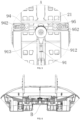
FIG. 1 is a first partial exploded view of a child safety seat according to an embodiment of the present invention; -
FIG. 2 is a second partial exploded view of the child safety seat according to the embodiment of the present invention; -
FIG. 3 is a third partial exploded view of the child safety seat according to the embodiment of the present invention; -
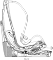
FIG. 4 is a partial structural view of the child safety seat in a locked state according to an embodiment of the present invention; -
FIG. 5 is an enlarged view of area A inFIG. 4 ; -
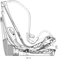
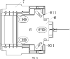
FIG. 6 is a partial cross-sectional view of the child safety seat in the locked state according to an embodiment of the present invention; -
FIG. 7 is an enlarged view of area B inFIG. 6 ; -
FIG. 8 is a partial structural view of the child safety seat according to the embodiment of the present invention when the rotating disc is unlocked and rotated; -
FIG. 9 is an enlarged view of area C inFIG. 8 ; -
FIG. 10 is a cross-sectional view of the child safety seat in the locked state according to the embodiment of the present invention; -
FIG. 11 is an enlarged view of area D inFIG. 10 ; -
FIG. 12 is a cross-sectional view of the child safety seat according to an embodiment of the present invention when the seat back angle adjustment function is unlocked; -
FIG. 13 is an enlarged view of area E inFIG. 12 ; -
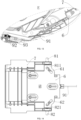
FIG. 14 is a structural view of assembly of the angle adjustment assembly, the adjustment handle and the handle fixing base when the seat back angle is locked according to an embodiment of the present invention; and -
FIG. 15 is a structural diagram of assembly of the angle adjustment assembly, the adjustment handle and the handle fixing base when the seat back angle is unlocked according to an embodiment of the present invention. - Reference signs are as follows:
1, base; 11, positioning gear slot; 2, rotating disc; 21, sliding groove; 3, slide rail fixed plate; 31, gear hole; 32, arc-shaped slide rail; 4, sliding shaft; 5, seat back; 6, adjustment handle; 61, first inclined slot; 62, second inclined slot; 7, handle fixing base; 8, angle adjustment assembly; 81, first gear pin; 811, first vertical rod; 82, second gear pin; 821, second vertical rod; 83, third reset member; 9, rotation adjusting assembly; 91, pull wire; 911, handle connection wire; 912, first branch wire; 9121, first fixed end; 913, second branch wire; 9131, second fixed end; 92, first pull wire rotating disc; 921, first wire guiding groove; 93, second pull wire rotating disc; 931, second wire guiding groove; 94, first rotation gear block; 941, first mounting cavity; 942, first slotted hole; 95, second rotation gear block; 951, second mounting cavity; 952, second slotted hole; 96, screw; 97, locking shaft; 98, first reset member; and 99, second reset member. - In order to make the above-mentioned objects, features and advantages of the present invention clearer and easier to understand, the specific embodiments of the present invention are described in detail below with reference to the accompanying drawings.
- In the description of the present invention, it is to be understood that the orientation or position relationship indicated by terms such as "upper" and "lower" is based on the orientation or position relationship when the product is normally operated.
- Terms "first" and "second" are used for descriptive purposes only and should not be understood as indicating or implying relative importance or implicitly indicating the number of the indicated technical features. Therefore, the features defined as "first" and "second" may explicitly or implicitly include at least one of the features.
- The present invention provides a one-drive-two structure for driving rotation of a rotating disc, as shown in
FIGS. 1 to 13 , including abase 1 and a rotatingdisc 2 rotatably connected to each other. Aseat back 5 is mounted on the rotatingdisc 2, and anadjustment handle 6 is movably connected to theseat back 5. Arotation adjusting assembly 9 is mounted on the rotatingdisc 2, and therotation adjusting assembly 9 includes apull wire 91, a first pullwire rotating disc 92, a second pullwire rotating disc 93, a firstrotation gear block 94 and a secondrotation gear block 95, and thebase 1 is provided with a plurality ofpositioning gear slots 11 adapted for cooperating with the firstrotation gear block 94 and the secondrotation gear block 95. Thepull wire 91 includes ahandle connection wire 911, afirst branch wire 912 and asecond branch wire 913, one end of thehandle connection wire 911 is connected to one end of thefirst branch wire 912 and one end of thesecond branch wire 913, and the other end thereof is connected to theadjustment handle 6. The other end of thefirst branch wire 912 bypasses the first pullwire rotating disc 92 and is connected to the firstrotation gear block 94. The other end of thesecond branch wire 913 bypasses the second pullwire rotating disc 93 and is connected to the secondrotation gear block 95. When theadjustment handle 6 is pulled and thepull wire 91 is driven to move, thefirst branch wire 912 drives the firstrotation gear block 94, and thesecond branch wire 913 drives the secondrotation gear block 95 to respectively disengage from thepositioning gear slots 11, and theseat back 5 is driven to rotate when a rotational force is continued to be applied to theadjustment handle 6. - Here, the first pull
wire rotating disc 92 is able to change the direction in which the force from thefirst branch wire 912 is applied, so that when thepull wire 91 is pulled forward, the firstrotation gear block 94 can move rightward. Similarly, the second pullwire rotating disc 93 is able to change the direction in which the force from thesecond branch wire 913 is applied, so that when thepull wire 91 is pulled forward, the secondrotation gear block 95 can move leftward. The firstrotation gear block 94 and the secondrotation gear block 95 are driven to move by thefirst branch wire 912 and thesecond branch wire 913 respectively, so that the tensile force on thefirst branch wire 912 and thesecond branch wire 913 is relatively small compared to the force when pulling two rotation gear blocks by only one wire, thus thefirst branch wire 912 and thesecond branch wire 913 are not prone to breakage. Thebase 1 has an axis that allows the rotatingdisc 2 to rotate 360°, and theseat back 5 fixedly mounted on the rotatingdisc 2 can rotate 360° relative to thebase 1 along with the rotatingdisc 2, without idling, thereby improving the user's operating experience. Theadjustment handle 6 is able to move forward and backward relative to theseat back 5. When the operator pulls the adjustment handle 6 to move forward relative to the seat back 5, thepull wire 91 also moves forward, and thefirst branch wire 912 of thepull wire 91 drives the firstrotation gear block 94 to move, and thesecond branch wire 913 drives the secondrotation gear block 95 to move, so that the firstrotation gear block 94 and the secondrotation gear block 95 retract and approach each other in the left and right direction of therotating disc 2, so as to disengage from thepositioning gear slots 11, releasing the rotation function of the seat back 5. The operator continues to apply a rotating force on the adjustment handle 6 to push the seat back 5 to rotate relative to thebase 1. In this embodiment, the number of thepositioning gear slots 11 is four, which are divided into two groups. When the seat back 5 faces forward, the firstrotation gear block 94 and the secondrotation gear block 95 cooperate with thepositioning gear slots 11 on the left and right respectively. When the seat back 5 faces the left or right side, the firstrotation gear block 94 and the secondrotation gear block 95 cooperate with thepositioning gear slots 11 in the front and rear respectively. In addition, the number ofpositioning gear slots 11 may also be other even numbers. When the operator releases theadjustment handle 6, the adjustment handle 6 is automatically reset under the action of the reset member, and the reset member is a compression spring. The tensile strength of thehandle connection wire 911 is greater than the tensile strength of thefirst branch wire 912 and thesecond branch wire 913. - The one-drive-two structure for driving rotation of a rotating disc in this embodiment utilizes the cooperation between the first
rotation gear block 94 and the secondrotation gear block 95 and thepositioning gear slots 11 to lock the relative position between the seat back 5 and thebase 1, and the adjustment handle 6 connected to thepull wire 91 is provided on the seat back 5. Thepull wire 91 includes thefirst branch wire 912 for driving the firstrotation gear block 94 to move and thesecond branch wire 913 for driving the secondrotation gear block 95 to move. When the operator pulls theadjustment handle 6, thepull wire 91 can be moved to eventually drive the firstrotation gear block 94 and the secondrotation gear block 95 to disengage from thepositioning gear slots 11, thereby realizing the unlocking of the rotation function of the seat back 5. In this design, the tensile force on thefirst branch wire 912 and thesecond branch wire 913 is relatively small, making them not prone to breakage. Additionally, the transmission components are eliminated, so that the overall structure is simple and the requirements for component precision are lower, resulting in easier processing and lower manufacturing costs. - Optionally, in combination with
FIGS. 2 ,4 and5 , the first pullwire rotating disc 92 and the second pullwire rotating disc 93 are both rotationally connected to therotating disc 2. The design of the rotational connection can reduce the friction between thefirst branch wire 912 and the first pullwire rotating disc 92 and the friction between thesecond branch wire 913 and the second pullwire rotating disc 93, so that the movement of the firstrotation gear block 94 and the secondrotation gear block 95 is smoother. Two rotating shafts may be set on therotating disc 2 for mounting the first pullwire rotating disc 92 and the second pullwire rotating disc 93, respectively, or one rotating shaft may be set on therotating disc 2, and the first pullwire rotating disc 92 and the second pullwire rotating disc 93 are both rotationally mounted on the rotating shaft. - Optionally, in combination with
FIGS. 2 ,4 , and5 , therotation adjusting assembly 9 includes a lockingshaft 97 passing through the first pullwire rotating disc 92 and the second pullwire rotating disc 93 in sequence and is connected to therotating disc 2, and the first pullwire rotating disc 92 and the second pullwire rotating disc 93 are both rotationally connected to the lockingshaft 97. The first pullwire rotating disc 92 and the second pullwire rotating disc 93 are stacked on each other to reduce the occupied space. The lockingshaft 97 is preferably arranged between the firstrotation gear block 94 and the secondrotation gear block 95, so that the pulling direction of thefirst branch wire 912 and the second pulling direction coincides with the left and right direction of therotating disc 2, so that the firstrotation gear block 94 and the secondrotation gear block 95 are smoothly driven by thepull wire 91 to move. - Optionally, in combination with
FIGS. 2 ,6 , and7 , the first pullwire rotating disc 92 is provided with a firstwire guiding groove 921 that cooperates with thefirst branch wire 912, and the second pullwire rotating disc 93 is provided with a secondwire guiding groove 931 that cooperates with thesecond branch wire 913. The firstwire guiding groove 921 is arranged to prevent thefirst branch wire 912 from being separated from the first pullwire rotating disc 92 when the firstrotation gear block 94 is pulled by thefirst branch wire 912. The secondwire guiding groove 931 is arranged to prevent thesecond branch wire 913 from being separated from the second pullwire rotating disc 93 when the secondrotation gear block 95 is pulled by thesecond branch wire 913. - Optionally, in combination with
FIGS. 2 ,6 and7 , thefirst branch wire 912 is provided with a firstfixed end 9121, thesecond branch wire 913 is provided with a secondfixed end 9131, the firstrotation gear block 94 is provided with a first mountingcavity 941 for mounting the firstfixed end 9121, and the secondrotation gear block 95 is provided with a second mountingcavity 951 for mounting the secondfixed end 9131. - The first
fixed end 9121 is arranged at an end of thefirst branch wire 912, and the secondfixed end 9131 is arranged at an end of thesecond branch wire 913. Thefirst branch wire 912 is able to be connected and fixed to the firstrotation gear block 94 through the cooperation between the firstfixed end 9121 and the first mounting cavity, ensuring that thepull wire 91 drives the firstrotation gear block 94 to move stably and reliably. Thesecond branch wire 913 is able to be connected and fixed to the secondrotation gear block 95 through the cooperation between the secondfixed end 9131 and the second mounting cavity, ensuring that thepull wire 91 drives the secondrotation gear block 95 to move stably and reliably. - Optionally, in combination with
FIGS. 2 ,4 and5 , therotating disc 2 is provided with a slidinggroove 21 slidably connected to the firstrotation gear block 94 and the secondrotation gear block 95, and afirst reset member 98 and asecond reset member 99 are mounted in the slidinggroove 21, two ends of thefirst reset member 98 are respectively connected to the firstrotation gear block 94 and therotating disc 2, and two ends of thesecond reset member 99 are respectively connected to the secondrotation gear block 95 and therotating disc 2. The firstrotation gear block 94 is provided with a first slottedhole 942, and the secondrotation gear block 95 is provided with a second slottedhole 952, and therotation adjusting assembly 9 further includes twoscrews 96 which are respectively slidably engaged with the first slottedhole 942 and the second slottedhole 952, and the firstrotation gear block 94 and the secondrotation gear block 95 are respectively connected to therotating disc 2 through thescrews 96. - The
first reset member 98 and thesecond reset member 99 are compression springs. When thepull wire 91 is pulled forward by theadjustment handle 6, the firstrotation gear block 94 and the secondrotation gear block 95 approach each other in the left and right direction of therotating disc 2 and compress thefirst reset member 98 and thesecond reset member 99, respectively. When a desired rotational position is reached and the pulling force on thepull wire 91 is released, the firstrotation gear block 94 and the secondrotation gear block 95 automatically move away from each other under the elastic force of thefirst reset member 98 and thesecond reset member 99 respectively, so that the firstrotation gear block 94 and the secondrotation gear block 95 are able to match and be engaged with thepositioning gear slots 11 again, thereby ensuring a simple and reliable structure. The first slottedhole 942 and the second slottedhole 952 have a certain length, and a lengthwise direction thereof coincides with the left and right direction of therotating disc 2. Thescrews 96 are capable of limiting the upward and downward movement of the firstrotation gear block 94 and the secondrotation gear block 95, ensuring that the firstrotation gear block 94 and the secondrotation gear block 95 can move along a given direction. With the connection through thepull wire 91, the firstrotation gear block 94 and the secondrotation gear block 95 are driven to perform left and right translational movement by theadjustment handle 6, so that a 360° rotation can be achieved at any rotation position. - Optionally, in combination with
FIGS. 1 ,3 and10-15 , slide rail fixedplates 3 connected to therotating disc 2 and ahandle fixing base 7 connected to the seat back 5 are further provided. The seat back 5 is slidably connected to the slide rail fixedplates 3, and the adjustment handle 6 is movably connected to thehandle fixing base 7. Thehandle fixing base 7 is mounted with anangle adjustment assembly 8 for locking or unlocking a relative angular position between the seat back 5 and the slide rail fixedplates 3. Theangle adjustment assembly 8 is respectively connected to theadjustment handle 6 and the slide rail fixedplates 3. The adjustment handle 6 moves relative to thehandle fixing base 7 to drive theangle adjustment assembly 8 to lock or unlock the relative angular position between the seat back 5 and the slide rail fixedplates 3. - The slide rail fixed
plates 3 are fixedly connected to therotating disc 2 by means of screws, that is, the slide rail fixedplates 3 are capable of rotating synchronously with therotating disc 2. An outer sheath of thepull wire 91 is fixed on therotating disc 2 and thehandle fixing base 7, and thepull wire 91 can move freely within the outer sheath. Thehandle fixing base 7 is connected and fixed to the seat back 5 by means of screws, and the adjustment handle 6 is fixed on thehandle fixing base 7 and can move forward and backward relative to thehandle fixing base 7. When the adjustment handle 6 is pulled forward relative to the seat back 5, in addition to driving therotation adjusting assembly 9 to release the rotation function of therotating disc 2, it also drives theangle adjustment assembly 8 to move, so that the seat back 5 is unlocked from the slide rail fixedplates 3, and then the seat back 5 can be moved in the front and rear direction to adjust the angle relative to the slide rail fixedplates 3, thereby realizing the function of adjusting the angle of the seat back 5, which allows convenience and ease of use and diversified functions. - Optionally, in combination with
FIGS. 1 ,3 , and10-15 , theangle adjustment assembly 8 includes afirst gear pin 81 and asecond gear pin 82 mounted on thehandle fixing base 7, thefirst gear pin 81 is provided with a firstvertical rod 811, thesecond gear pin 82 is provided with a secondvertical rod 821, the adjustment handle 6 is provided with a firstinclined slot 61 in sliding engagement with the firstvertical rod 811 and a secondinclined slot 62 in sliding engagement with the secondvertical rod 821. The slide rail fixedplates 3 are provided with a plurality of gear holes 31 that are respectively adapted for cooperating with thefirst gear pin 81 and thesecond gear pin 82. - When the
first gear pin 81 and thesecond gear pin 82 are locked with the gear holes 31 respectively, thefirst gear pin 81 and thesecond gear pin 82 are in an extended state relative to thehandle fixing base 7, meanwhile the firstvertical rod 811 is located at a front end position of the firstinclined slot 61, and the secondvertical rod 821 is located at a front end position of the secondinclined slot 62. When the adjustment handle 6 is pulled forward, the firstvertical rod 811 moves to a rear end of the firstinclined slot 61 and the secondvertical rod 821 moves to a rear end of the secondinclined slot 62, allowing thefirst gear pin 81 and thesecond gear pin 82 to be retracted inwardly into thehandle fixing base 7, so that thefirst gear pin 81 and thesecond gear pin 82 are disengaged from the gear holes 31, thereby unlocking the relative angular position between the seat back 5 and the slide rail fixedplates 3. At this moment, when a force is applied to thehandle fixing base 7 in the front and rear direction, the seat back 5 can be pushed to adjust the angle relative to the slide rail fixedplates 3. This structure allows a smoother operation when adjusting the angle and achieves silent adjustment operation. The rear end of the firstinclined slot 61 and the rear end of the secondinclined slot 62 are close to each other, and the front end of the firstinclined slot 61 and the front end of the secondinclined slot 62 are distant from each other. Thehandle fixing base 7 is provided with corresponding grooves in which thefirst gear pin 81 and thesecond gear pin 82 are movable in the left and right direction. - Optionally, in combination with
FIGS. 1 ,3 , and10-15 , theangle adjustment assembly 8 includes athird reset member 83, two ends of thethird reset member 83 are respectively connected to thefirst gear pin 81 and thesecond gear pin 82. Thethird reset member 83 is a compression spring, and when the relative angle position between the seat back 5 and the slide rail fixedplates 3 is in an unlocked state, thethird reset member 83 is in a compressed state, and when the operator releases theadjustment handle 6, the elastic force of thethird reset member 83 pushes thefirst gear pin 81 and thesecond gear pin 82 to automatically reset to lock with the gear holes 31, ensuring a reliable structure. - Optionally, in combination with
FIGS. 1 ,3 , and10-15 , the seat back 5 is connected to slidingshafts 4, and the slide rail fixedplates 3 are provided with arc-shapedslide rails 32 slidably connected to the slidingshafts 4. - The arc-shaped
slide rail 32 has a certain length to allow angle adjustment to the seat back 5. The seat back 5 is slidably connected to the slide rail fixedplates 3 through the slidingshafts 4. When the operator pulls theadjustment handle 6, the adjustment handle 6 moves forward and drives thefirst gear pin 81 and thesecond gear pin 82 to retract inward through the firstinclined slot 61 and the secondinclined slot 62 respectively, so that thefirst gear pin 81 and thesecond gear pin 82 are separated from the gear holes 31 on the slide rail fixedplates 3, allowing the angle of the seat back 5 to be adjusted. When the required gear is adjusted, thefirst gear pin 81 and thesecond gear pin 82 are quickly shifted into gear under the force of thethird reset member 83, thereby completing the angle adjustment of the seat back 5. While the operator pulls theadjustment handle 6, the firstrotation gear block 94 and the secondrotation gear block 95 are also driven to move inwardly through thepull wire 91, and thefirst reset member 98 and thesecond reset member 99 are compressed, so that the firstrotation gear block 94 and the secondrotation gear block 95 are separated from thepositioning gear slots 11. Meanwhile the operator can adjust the rotation position of the seat back 5. When it is adjusted to the required position, the adjustment handle 6 is released, the firstrotation gear block 94 and the secondrotation gear block 95 will quickly engage the corresponding position under the force of thefirst reset member 98 and thesecond reset member 99, respectively, thereby completing the rotation adjustment. Thepull wire 91 is able to achieve the angle adjustment of the seat back 5 at any rotation angle. - Another embodiment of the present invention provides a child safety seat, including the above-mentioned one-drive-two structure for driving rotation of a rotating disc.
- The child safety seat in this embodiment utilizes the first
rotation gear block 94 and the secondrotation gear block 95 in cooperation with thepositioning gear slots 11 to lock the relative position between the seat back 5 and thebase 1, and anadjustment handle 6 connected to apull wire 91 is provided on the seat back 5. Thepull wire 91 includes afirst branch wire 912 for driving the firstrotation gear block 94 to move and asecond branch wire 913 for driving the secondrotation gear block 95 to move. When the operator pulls theadjustment handle 6, thepull wire 91 is moved to eventually drive the firstrotation gear block 94 and the secondrotation gear block 95 to disengage from thepositioning gear slots 11, thereby realizing the unlocking of the rotation function of the seat back 5. In this design, the tensile force on thefirst branch wire 912 and thesecond branch wire 913 is relatively small, making them not prone to breakage. Additionally, the transmission components are eliminated, so that the overall structure is simple and the requirements for component precision are lower, resulting in easier processing and lower manufacturing costs - Although the disclosure is described above, the protection scope of the present disclosure is not limited thereto. A person skilled in the art may make various changes and modifications without departing from the spirit and scope of the disclosure, and these changes and modifications fall within the protection scope of the present invention.
Claims (10)
- A one-drive-two structure for driving rotation of a rotating disc, characterized in that it comprises a base (1) and a rotating disc (2) rotatably connected to each other, a seat back (5) is mounted on the rotating disc (2), and the seat back (5) is movably connected to an adjustment handle (6), a rotation adjusting assembly (9) is mounted on the rotating disc (2), the rotation adjusting assembly (9) comprises a pull wire (91), a first pull wire rotating disc (92), a second pull wire rotating disc (93), a first rotation gear block (94) and a second rotation gear block (95), the base (1) is provided with a plurality of positioning gear slots (11) adapted for cooperating with the first rotation gear block (94) and the second rotation gear block (95), the pull wire (91) comprises a handle connection wire (911), a first branch wire (912) and a second branch wire (913), an end of the handle connection wire (911) is connected to an end of the first branch wire (912) and an end of the second branch wire (913), and another end thereof is connected to the adjustment handle (6), another end of the first branch wire (912) bypasses the first pull wire rotating disc (92) and is connected to the first rotation gear block (94), another end of the second branch wire (913) bypasses the second pull wire rotating disc (93) and is connected to the second rotation gear block (95); when the adjustment handle (6) is pulled and the pull wire (91) is driven to move, the first branch wire (912) drives the first rotation gear block (94) and the second branch wire (913) drives the second rotation gear block (95) to separate from the positioning gear slots (11) respectively, and the seat back (5) is driven to rotate when a rotational force is further applied to the adjustment handle (6).
- The one-drive-two structure for driving rotation of a rotating disc according to claim 1, characterized in that the first pull wire rotating disc (92) and the second pull wire rotating disc (93) are both rotationally connected to the rotating disc (2).
- The one-to-two rotating disc rotating structure described in claim 2, characterized in that the rotation adjusting assembly (9) comprises a locking shaft (97), and the locking shaft (97) passes through the first pull wire rotating disc (92) and the second pull wire rotating disc (93) in sequence and is connected to the rotating disc (2), and the first pull wire rotating disc (92) and the second pull wire rotating disc (93) are both rotationally connected to the locking shaft (97).
- The one-drive-two structure for driving rotation of a rotating disc according to claim 1, characterized in that the first pull wire rotating disc (92) is provided with a first wire guiding groove (921) cooperating with the first branch wire (912), and the second pull wire rotating disc (93) is provided with a second wire guiding groove (931) cooperating with the second branch wire (913).
- The one-drive-two structure for driving rotation of a rotating disc according to claim 1, characterized in that the first branch wire (912) is provided with a first fixed end (9121), the second branch wire (913) is provided with a second fixed end (9131), the first rotation gear block (94) is provided with a first mounting cavity (941) for mounting the first fixed end (9121), and the second rotation gear block (95) is provided with a second mounting cavity (951) for mounting the second fixed end (9131).
- The one-drive-two structure for driving rotation of a rotating disc according to claim 1, characterized in that the rotating disc (2) is provided with a sliding groove (21) slidably connected to the first rotation gear block (94) and the second rotation gear block (95), and a first reset member (98) and a second reset member (99) are mounted in the sliding groove (21), two ends of the first reset member (98) are respectively connected to the first rotation gear block (94) and the rotating disc (2), and two ends of the second reset member (99) are respectively connected to the second rotation gear block (95) and the rotating disc (2), the first rotation gear block (94) is provided with a first slotted hole (942), and the second rotation gear block (95) is provided with a second slotted hole (952), the rotation adjusting assembly (9) further comprises two screws (96) respectively slidingly cooperated with the first slotted hole (942) and the second slotted hole (952), the first rotation gear block (94) and the second rotation gear block (95) are respectively connected to the rotating disc (2) through the screws (96).
- The one-drive-two structure for driving rotation of a rotating disc according to claim 1, characterized in that it further comprises slide rail fixed plates (3) connected to the rotating disc (2) and a handle fixing base (7) connected to the seat back (5), the seat back (5) is slidably connected to the slide rail fixed plates (3), the adjustment handle (6) is movably connected to the handle fixing base (7), the handle fixing base (7) is mounted with an angle adjustment assembly (8) for locking or unlocking a relative angular position between the seat back (5) and the slide rail fixed plates (3), the angle adjustment assembly (8) is respectively connected to the adjustment handle (6) and the slide rail fixed plates (3), and when the adjustment handle (6) moves relative to the handle fixing base (7), the angle adjustment assembly (8) is driven to lock or unlock the relative angular position between the seat back (5) and the slide rail fixed plates (3).
- The one-drive-two structure for driving rotation of a rotating disc according to claim 7, characterized in that the angle adjustment assembly (8) comprises a first gear pin (81) and a second gear pin (82) mounted on the handle fixing base (7), the first gear pin (81) is provided with a first vertical rod (811), the second gear pin (82) is provided with a second vertical rod (821), the adjustment handle (6) is provided with a first inclined slot (61) slidingly engaged with the first vertical rod (811) and a second inclined slot (62) slidingly engaged with the second vertical rod (821), and the slide rail fixed plates (3) are provided with a plurality of gear holes (31) adapted for cooperating with the first gear pin (81) and the second gear pin (82), respectively.
- The one-drive-two structure for driving rotation of a rotating disc according to claim 8, characterized in that the angle adjustment assembly (8) comprises a third reset member (83), and two ends of the third reset member (83) are respectively connected to the first gear pin (81) and the second gear pin (82), the seat back (5) is connected to a sliding shaft (4), and the slide rail fixed plates (3) are provided with arc-shaped slide rails (32) slidably connected to the sliding shaft (4).
- A child safety seat, characterized in that it comprises the one-drive-two structure for driving rotation of a rotating disc according to any one of claims 1 to 9.
Applications Claiming Priority (2)
| Application Number | Priority Date | Filing Date | Title |
|---|---|---|---|
| CN202223143447.3U CN218876986U (en) | 2022-11-25 | 2022-11-25 | Structure for driving rotating disc to rotate by one-driving-two and child safety seat |
| PCT/CN2023/102057 WO2024109013A1 (en) | 2022-11-25 | 2023-06-25 | One-drive-two structure for driving rotation of rotating disc, and child safety seat |
Publications (2)
| Publication Number | Publication Date |
|---|---|
| EP4582310A1 true EP4582310A1 (en) | 2025-07-09 |
| EP4582310A4 EP4582310A4 (en) | 2026-01-14 |
Family
ID=85952650
Family Applications (1)
| Application Number | Title | Priority Date | Filing Date |
|---|---|---|---|
| EP23893113.3A Pending EP4582310A4 (en) | 2022-11-25 | 2023-06-25 | STRUCTURE WITH ONE DRIVE AND TWO FOR DRIVING THE TURN OF A TURNTABLE AND CHILD SAFETY SEAT |
Country Status (3)
| Country | Link |
|---|---|
| EP (1) | EP4582310A4 (en) |
| CN (1) | CN218876986U (en) |
| WO (1) | WO2024109013A1 (en) |
Families Citing this family (2)
| Publication number | Priority date | Publication date | Assignee | Title |
|---|---|---|---|---|
| CN218876986U (en) * | 2022-11-25 | 2023-04-18 | 宁波宝贝第一母婴用品有限公司 | Structure for driving rotating disc to rotate by one-driving-two and child safety seat |
| CN220700964U (en) * | 2023-07-14 | 2024-04-02 | 宁波宝贝第一母婴用品有限公司 | A child safety seat with electric rotation function |
Family Cites Families (8)
| Publication number | Priority date | Publication date | Assignee | Title |
|---|---|---|---|---|
| US7073859B1 (en) * | 2004-08-19 | 2006-07-11 | Pamela S. Wilson | Pivotable child seat for use in a vehicle |
| US20090091167A1 (en) * | 2007-10-04 | 2009-04-09 | Think/Thing | Child seating system and method |
| CN211765088U (en) * | 2020-01-21 | 2020-10-27 | 麦克英孚(宁波)婴童用品有限公司 | A spin-pull headrest adjustment mechanism |
| CN214240525U (en) * | 2020-12-16 | 2021-09-21 | 欧颂德婴童用品(湖北)有限公司 | Linkage unlocking assembly for angle adjustment and rotation adjustment and child seat |
| CN216994003U (en) * | 2021-12-10 | 2022-07-19 | 扬州莱特斯婴童用品有限公司 | Rotary locking structure |
| CN216467462U (en) * | 2021-12-27 | 2022-05-10 | 宁波宝贝第一母婴用品有限公司 | Safety seats |
| CN218858229U (en) * | 2022-11-25 | 2023-04-14 | 宁波宝贝第一母婴用品有限公司 | A structure capable of adjusting the rotation of a rotating disc with one hand and a child safety seat |
| CN218876986U (en) * | 2022-11-25 | 2023-04-18 | 宁波宝贝第一母婴用品有限公司 | Structure for driving rotating disc to rotate by one-driving-two and child safety seat |
-
2022
- 2022-11-25 CN CN202223143447.3U patent/CN218876986U/en active Active
-
2023
- 2023-06-25 EP EP23893113.3A patent/EP4582310A4/en active Pending
- 2023-06-25 WO PCT/CN2023/102057 patent/WO2024109013A1/en not_active Ceased
Also Published As
| Publication number | Publication date |
|---|---|
| EP4582310A4 (en) | 2026-01-14 |
| WO2024109013A1 (en) | 2024-05-30 |
| CN218876986U (en) | 2023-04-18 |
Similar Documents
| Publication | Publication Date | Title |
|---|---|---|
| EP4588716A1 (en) | Structure capable of adjusting rotation of rotating disk by single hand and child safety seat | |
| EP4582310A1 (en) | One-drive-two structure for driving rotation of rotating disc, and child safety seat | |
| US5033805A (en) | Drawer slide assembly with releasable lock mechanism | |
| EP3833592B1 (en) | Unlock device and stroller | |
| CN110626223A (en) | Clutch mechanism of electric sliding rail | |
| EP3960534B1 (en) | Easy disassembly and installation base and carseat | |
| CN117755528A (en) | Separating mechanism facing microsatellite | |
| CN108518131B (en) | Lockset and rotary limiting device thereof | |
| US20230099957A1 (en) | Electrically controlled sliding apparatus for photographic equipment and locking assembly thereof | |
| US12485804B2 (en) | Child safety seat with reversible ISOFIX connectors | |
| US20250235001A1 (en) | Base frame assembly and chair having the same | |
| CN219133922U (en) | Rotary gear adjustment structure and child safety seat | |
| CN116565743B (en) | Unlocking structure of drawer seat | |
| CN219451992U (en) | Quick locking mechanism for multifunctional ladder | |
| CN112739947A (en) | Mechanical locking device, support arm of ultrasonic equipment and ultrasonic equipment | |
| CN110271574B (en) | Manual-automatic integrated reversing system for seat | |
| CN116491775A (en) | A slide rail device and a drawer cabinet | |
| CN212271838U (en) | Unlocking key | |
| CN218912546U (en) | Overload-preventing motor-driven cushion lock | |
| CN223672327U (en) | Chair seat mechanism and child seat | |
| US20240034199A1 (en) | System for locking a continuous-adjustment slide | |
| CN217969116U (en) | Foot brake mechanism and medical equipment | |
| RU2829835C1 (en) | Door lock | |
| CN223514486U (en) | Interlocking device for drawer cabinet and drawer cabinet | |
| CN223825374U (en) | Buckle structure |
Legal Events
| Date | Code | Title | Description |
|---|---|---|---|
| STAA | Information on the status of an ep patent application or granted ep patent |
Free format text: STATUS: THE INTERNATIONAL PUBLICATION HAS BEEN MADE |
|
| PUAI | Public reference made under article 153(3) epc to a published international application that has entered the european phase |
Free format text: ORIGINAL CODE: 0009012 |
|
| STAA | Information on the status of an ep patent application or granted ep patent |
Free format text: STATUS: REQUEST FOR EXAMINATION WAS MADE |
|
| 17P | Request for examination filed |
Effective date: 20250404 |
|
| AK | Designated contracting states |
Kind code of ref document: A1 Designated state(s): AL AT BE BG CH CY CZ DE DK EE ES FI FR GB GR HR HU IE IS IT LI LT LU LV MC ME MK MT NL NO PL PT RO RS SE SI SK SM TR |
|
| STAA | Information on the status of an ep patent application or granted ep patent |
Free format text: STATUS: EXAMINATION IS IN PROGRESS |
|
| A4 | Supplementary search report drawn up and despatched |
Effective date: 20251212 |
|
| RIC1 | Information provided on ipc code assigned before grant |
Ipc: B60N 2/28 20060101AFI20251208BHEP |
|
| 17Q | First examination report despatched |
Effective date: 20251219 |
|
| DAV | Request for validation of the european patent (deleted) | ||
| DAX | Request for extension of the european patent (deleted) |