EP4582306A1 - Battery self-heating system and vehicle - Google Patents
Battery self-heating system and vehicle Download PDFInfo
- Publication number
- EP4582306A1 EP4582306A1 EP23858697.8A EP23858697A EP4582306A1 EP 4582306 A1 EP4582306 A1 EP 4582306A1 EP 23858697 A EP23858697 A EP 23858697A EP 4582306 A1 EP4582306 A1 EP 4582306A1
- Authority
- EP
- European Patent Office
- Prior art keywords
- switch
- battery pack
- heating
- module
- winding
- Prior art date
- Legal status (The legal status is an assumption and is not a legal conclusion. Google has not performed a legal analysis and makes no representation as to the accuracy of the status listed.)
- Pending
Links
Images


Classifications
-
- H—ELECTRICITY
- H01—ELECTRIC ELEMENTS
- H01M—PROCESSES OR MEANS, e.g. BATTERIES, FOR THE DIRECT CONVERSION OF CHEMICAL ENERGY INTO ELECTRICAL ENERGY
- H01M10/00—Secondary cells; Manufacture thereof
- H01M10/60—Heating or cooling; Temperature control
- H01M10/61—Types of temperature control
- H01M10/615—Heating or keeping warm
-
- B—PERFORMING OPERATIONS; TRANSPORTING
- B60—VEHICLES IN GENERAL
- B60L—PROPULSION OF ELECTRICALLY-PROPELLED VEHICLES; SUPPLYING ELECTRIC POWER FOR AUXILIARY EQUIPMENT OF ELECTRICALLY-PROPELLED VEHICLES; ELECTRODYNAMIC BRAKE SYSTEMS FOR VEHICLES IN GENERAL; MAGNETIC SUSPENSION OR LEVITATION FOR VEHICLES; MONITORING OPERATING VARIABLES OF ELECTRICALLY-PROPELLED VEHICLES; ELECTRIC SAFETY DEVICES FOR ELECTRICALLY-PROPELLED VEHICLES
- B60L1/00—Supplying electric power to auxiliary equipment of vehicles
- B60L1/02—Supplying electric power to auxiliary equipment of vehicles to electric heating circuits
-
- B—PERFORMING OPERATIONS; TRANSPORTING
- B60—VEHICLES IN GENERAL
- B60L—PROPULSION OF ELECTRICALLY-PROPELLED VEHICLES; SUPPLYING ELECTRIC POWER FOR AUXILIARY EQUIPMENT OF ELECTRICALLY-PROPELLED VEHICLES; ELECTRODYNAMIC BRAKE SYSTEMS FOR VEHICLES IN GENERAL; MAGNETIC SUSPENSION OR LEVITATION FOR VEHICLES; MONITORING OPERATING VARIABLES OF ELECTRICALLY-PROPELLED VEHICLES; ELECTRIC SAFETY DEVICES FOR ELECTRICALLY-PROPELLED VEHICLES
- B60L15/00—Methods, circuits, or devices for controlling the traction-motor speed of electrically-propelled vehicles
- B60L15/007—Physical arrangements or structures of drive train converters specially adapted for the propulsion motors of electric vehicles
-
- B—PERFORMING OPERATIONS; TRANSPORTING
- B60—VEHICLES IN GENERAL
- B60L—PROPULSION OF ELECTRICALLY-PROPELLED VEHICLES; SUPPLYING ELECTRIC POWER FOR AUXILIARY EQUIPMENT OF ELECTRICALLY-PROPELLED VEHICLES; ELECTRODYNAMIC BRAKE SYSTEMS FOR VEHICLES IN GENERAL; MAGNETIC SUSPENSION OR LEVITATION FOR VEHICLES; MONITORING OPERATING VARIABLES OF ELECTRICALLY-PROPELLED VEHICLES; ELECTRIC SAFETY DEVICES FOR ELECTRICALLY-PROPELLED VEHICLES
- B60L50/00—Electric propulsion with power supplied within the vehicle
- B60L50/50—Electric propulsion with power supplied within the vehicle using propulsion power supplied by batteries or fuel cells
- B60L50/60—Electric propulsion with power supplied within the vehicle using propulsion power supplied by batteries or fuel cells using power supplied by batteries
-
- B—PERFORMING OPERATIONS; TRANSPORTING
- B60—VEHICLES IN GENERAL
- B60L—PROPULSION OF ELECTRICALLY-PROPELLED VEHICLES; SUPPLYING ELECTRIC POWER FOR AUXILIARY EQUIPMENT OF ELECTRICALLY-PROPELLED VEHICLES; ELECTRODYNAMIC BRAKE SYSTEMS FOR VEHICLES IN GENERAL; MAGNETIC SUSPENSION OR LEVITATION FOR VEHICLES; MONITORING OPERATING VARIABLES OF ELECTRICALLY-PROPELLED VEHICLES; ELECTRIC SAFETY DEVICES FOR ELECTRICALLY-PROPELLED VEHICLES
- B60L53/00—Methods of charging batteries, specially adapted for electric vehicles; Charging stations or on-board charging equipment therefor; Exchange of energy storage elements in electric vehicles
-
- B—PERFORMING OPERATIONS; TRANSPORTING
- B60—VEHICLES IN GENERAL
- B60L—PROPULSION OF ELECTRICALLY-PROPELLED VEHICLES; SUPPLYING ELECTRIC POWER FOR AUXILIARY EQUIPMENT OF ELECTRICALLY-PROPELLED VEHICLES; ELECTRODYNAMIC BRAKE SYSTEMS FOR VEHICLES IN GENERAL; MAGNETIC SUSPENSION OR LEVITATION FOR VEHICLES; MONITORING OPERATING VARIABLES OF ELECTRICALLY-PROPELLED VEHICLES; ELECTRIC SAFETY DEVICES FOR ELECTRICALLY-PROPELLED VEHICLES
- B60L53/00—Methods of charging batteries, specially adapted for electric vehicles; Charging stations or on-board charging equipment therefor; Exchange of energy storage elements in electric vehicles
- B60L53/10—Methods of charging batteries, specially adapted for electric vehicles; Charging stations or on-board charging equipment therefor; Exchange of energy storage elements in electric vehicles characterised by the energy transfer between the charging station and the vehicle
- B60L53/11—DC charging controlled by the charging station, e.g. mode 4
-
- B—PERFORMING OPERATIONS; TRANSPORTING
- B60—VEHICLES IN GENERAL
- B60L—PROPULSION OF ELECTRICALLY-PROPELLED VEHICLES; SUPPLYING ELECTRIC POWER FOR AUXILIARY EQUIPMENT OF ELECTRICALLY-PROPELLED VEHICLES; ELECTRODYNAMIC BRAKE SYSTEMS FOR VEHICLES IN GENERAL; MAGNETIC SUSPENSION OR LEVITATION FOR VEHICLES; MONITORING OPERATING VARIABLES OF ELECTRICALLY-PROPELLED VEHICLES; ELECTRIC SAFETY DEVICES FOR ELECTRICALLY-PROPELLED VEHICLES
- B60L53/00—Methods of charging batteries, specially adapted for electric vehicles; Charging stations or on-board charging equipment therefor; Exchange of energy storage elements in electric vehicles
- B60L53/10—Methods of charging batteries, specially adapted for electric vehicles; Charging stations or on-board charging equipment therefor; Exchange of energy storage elements in electric vehicles characterised by the energy transfer between the charging station and the vehicle
- B60L53/14—Conductive energy transfer
- B60L53/16—Connectors, e.g. plugs or sockets, specially adapted for charging electric vehicles
-
- B—PERFORMING OPERATIONS; TRANSPORTING
- B60—VEHICLES IN GENERAL
- B60L—PROPULSION OF ELECTRICALLY-PROPELLED VEHICLES; SUPPLYING ELECTRIC POWER FOR AUXILIARY EQUIPMENT OF ELECTRICALLY-PROPELLED VEHICLES; ELECTRODYNAMIC BRAKE SYSTEMS FOR VEHICLES IN GENERAL; MAGNETIC SUSPENSION OR LEVITATION FOR VEHICLES; MONITORING OPERATING VARIABLES OF ELECTRICALLY-PROPELLED VEHICLES; ELECTRIC SAFETY DEVICES FOR ELECTRICALLY-PROPELLED VEHICLES
- B60L53/00—Methods of charging batteries, specially adapted for electric vehicles; Charging stations or on-board charging equipment therefor; Exchange of energy storage elements in electric vehicles
- B60L53/20—Methods of charging batteries, specially adapted for electric vehicles; Charging stations or on-board charging equipment therefor; Exchange of energy storage elements in electric vehicles characterised by converters located in the vehicle
- B60L53/24—Using the vehicle's propulsion converter for charging
-
- B—PERFORMING OPERATIONS; TRANSPORTING
- B60—VEHICLES IN GENERAL
- B60L—PROPULSION OF ELECTRICALLY-PROPELLED VEHICLES; SUPPLYING ELECTRIC POWER FOR AUXILIARY EQUIPMENT OF ELECTRICALLY-PROPELLED VEHICLES; ELECTRODYNAMIC BRAKE SYSTEMS FOR VEHICLES IN GENERAL; MAGNETIC SUSPENSION OR LEVITATION FOR VEHICLES; MONITORING OPERATING VARIABLES OF ELECTRICALLY-PROPELLED VEHICLES; ELECTRIC SAFETY DEVICES FOR ELECTRICALLY-PROPELLED VEHICLES
- B60L53/00—Methods of charging batteries, specially adapted for electric vehicles; Charging stations or on-board charging equipment therefor; Exchange of energy storage elements in electric vehicles
- B60L53/30—Constructional details of charging stations
- B60L53/31—Charging columns specially adapted for electric vehicles
-
- B—PERFORMING OPERATIONS; TRANSPORTING
- B60—VEHICLES IN GENERAL
- B60L—PROPULSION OF ELECTRICALLY-PROPELLED VEHICLES; SUPPLYING ELECTRIC POWER FOR AUXILIARY EQUIPMENT OF ELECTRICALLY-PROPELLED VEHICLES; ELECTRODYNAMIC BRAKE SYSTEMS FOR VEHICLES IN GENERAL; MAGNETIC SUSPENSION OR LEVITATION FOR VEHICLES; MONITORING OPERATING VARIABLES OF ELECTRICALLY-PROPELLED VEHICLES; ELECTRIC SAFETY DEVICES FOR ELECTRICALLY-PROPELLED VEHICLES
- B60L53/00—Methods of charging batteries, specially adapted for electric vehicles; Charging stations or on-board charging equipment therefor; Exchange of energy storage elements in electric vehicles
- B60L53/60—Monitoring or controlling charging stations
- B60L53/62—Monitoring or controlling charging stations in response to charging parameters, e.g. current, voltage or electrical charge
-
- B—PERFORMING OPERATIONS; TRANSPORTING
- B60—VEHICLES IN GENERAL
- B60L—PROPULSION OF ELECTRICALLY-PROPELLED VEHICLES; SUPPLYING ELECTRIC POWER FOR AUXILIARY EQUIPMENT OF ELECTRICALLY-PROPELLED VEHICLES; ELECTRODYNAMIC BRAKE SYSTEMS FOR VEHICLES IN GENERAL; MAGNETIC SUSPENSION OR LEVITATION FOR VEHICLES; MONITORING OPERATING VARIABLES OF ELECTRICALLY-PROPELLED VEHICLES; ELECTRIC SAFETY DEVICES FOR ELECTRICALLY-PROPELLED VEHICLES
- B60L58/00—Methods or circuit arrangements for monitoring or controlling batteries or fuel cells, specially adapted for electric vehicles
- B60L58/10—Methods or circuit arrangements for monitoring or controlling batteries or fuel cells, specially adapted for electric vehicles for monitoring or controlling batteries
-
- B—PERFORMING OPERATIONS; TRANSPORTING
- B60—VEHICLES IN GENERAL
- B60L—PROPULSION OF ELECTRICALLY-PROPELLED VEHICLES; SUPPLYING ELECTRIC POWER FOR AUXILIARY EQUIPMENT OF ELECTRICALLY-PROPELLED VEHICLES; ELECTRODYNAMIC BRAKE SYSTEMS FOR VEHICLES IN GENERAL; MAGNETIC SUSPENSION OR LEVITATION FOR VEHICLES; MONITORING OPERATING VARIABLES OF ELECTRICALLY-PROPELLED VEHICLES; ELECTRIC SAFETY DEVICES FOR ELECTRICALLY-PROPELLED VEHICLES
- B60L58/00—Methods or circuit arrangements for monitoring or controlling batteries or fuel cells, specially adapted for electric vehicles
- B60L58/10—Methods or circuit arrangements for monitoring or controlling batteries or fuel cells, specially adapted for electric vehicles for monitoring or controlling batteries
- B60L58/18—Methods or circuit arrangements for monitoring or controlling batteries or fuel cells, specially adapted for electric vehicles for monitoring or controlling batteries of two or more battery modules
-
- B—PERFORMING OPERATIONS; TRANSPORTING
- B60—VEHICLES IN GENERAL
- B60L—PROPULSION OF ELECTRICALLY-PROPELLED VEHICLES; SUPPLYING ELECTRIC POWER FOR AUXILIARY EQUIPMENT OF ELECTRICALLY-PROPELLED VEHICLES; ELECTRODYNAMIC BRAKE SYSTEMS FOR VEHICLES IN GENERAL; MAGNETIC SUSPENSION OR LEVITATION FOR VEHICLES; MONITORING OPERATING VARIABLES OF ELECTRICALLY-PROPELLED VEHICLES; ELECTRIC SAFETY DEVICES FOR ELECTRICALLY-PROPELLED VEHICLES
- B60L58/00—Methods or circuit arrangements for monitoring or controlling batteries or fuel cells, specially adapted for electric vehicles
- B60L58/10—Methods or circuit arrangements for monitoring or controlling batteries or fuel cells, specially adapted for electric vehicles for monitoring or controlling batteries
- B60L58/24—Methods or circuit arrangements for monitoring or controlling batteries or fuel cells, specially adapted for electric vehicles for monitoring or controlling batteries for controlling the temperature of batteries
- B60L58/25—Methods or circuit arrangements for monitoring or controlling batteries or fuel cells, specially adapted for electric vehicles for monitoring or controlling batteries for controlling the temperature of batteries by controlling the electric load
-
- B—PERFORMING OPERATIONS; TRANSPORTING
- B60—VEHICLES IN GENERAL
- B60L—PROPULSION OF ELECTRICALLY-PROPELLED VEHICLES; SUPPLYING ELECTRIC POWER FOR AUXILIARY EQUIPMENT OF ELECTRICALLY-PROPELLED VEHICLES; ELECTRODYNAMIC BRAKE SYSTEMS FOR VEHICLES IN GENERAL; MAGNETIC SUSPENSION OR LEVITATION FOR VEHICLES; MONITORING OPERATING VARIABLES OF ELECTRICALLY-PROPELLED VEHICLES; ELECTRIC SAFETY DEVICES FOR ELECTRICALLY-PROPELLED VEHICLES
- B60L58/00—Methods or circuit arrangements for monitoring or controlling batteries or fuel cells, specially adapted for electric vehicles
- B60L58/10—Methods or circuit arrangements for monitoring or controlling batteries or fuel cells, specially adapted for electric vehicles for monitoring or controlling batteries
- B60L58/24—Methods or circuit arrangements for monitoring or controlling batteries or fuel cells, specially adapted for electric vehicles for monitoring or controlling batteries for controlling the temperature of batteries
- B60L58/27—Methods or circuit arrangements for monitoring or controlling batteries or fuel cells, specially adapted for electric vehicles for monitoring or controlling batteries for controlling the temperature of batteries by heating
-
- H—ELECTRICITY
- H01—ELECTRIC ELEMENTS
- H01M—PROCESSES OR MEANS, e.g. BATTERIES, FOR THE DIRECT CONVERSION OF CHEMICAL ENERGY INTO ELECTRICAL ENERGY
- H01M10/00—Secondary cells; Manufacture thereof
- H01M10/42—Methods or arrangements for servicing or maintenance of secondary cells or secondary half-cells
- H01M10/44—Methods for charging or discharging
-
- H—ELECTRICITY
- H01—ELECTRIC ELEMENTS
- H01M—PROCESSES OR MEANS, e.g. BATTERIES, FOR THE DIRECT CONVERSION OF CHEMICAL ENERGY INTO ELECTRICAL ENERGY
- H01M10/00—Secondary cells; Manufacture thereof
- H01M10/60—Heating or cooling; Temperature control
- H01M10/62—Heating or cooling; Temperature control specially adapted for specific applications
- H01M10/625—Vehicles
-
- H—ELECTRICITY
- H01—ELECTRIC ELEMENTS
- H01M—PROCESSES OR MEANS, e.g. BATTERIES, FOR THE DIRECT CONVERSION OF CHEMICAL ENERGY INTO ELECTRICAL ENERGY
- H01M10/00—Secondary cells; Manufacture thereof
- H01M10/60—Heating or cooling; Temperature control
- H01M10/63—Control systems
- H01M10/637—Control systems characterised by the use of reversible temperature-sensitive devices, e.g. NTC, PTC or bimetal devices; characterised by control of the internal current flowing through the cells, e.g. by switching
-
- H—ELECTRICITY
- H01—ELECTRIC ELEMENTS
- H01M—PROCESSES OR MEANS, e.g. BATTERIES, FOR THE DIRECT CONVERSION OF CHEMICAL ENERGY INTO ELECTRICAL ENERGY
- H01M10/00—Secondary cells; Manufacture thereof
- H01M10/60—Heating or cooling; Temperature control
- H01M10/65—Means for temperature control structurally associated with the cells
- H01M10/657—Means for temperature control structurally associated with the cells by electric or electromagnetic means
-
- H—ELECTRICITY
- H01—ELECTRIC ELEMENTS
- H01M—PROCESSES OR MEANS, e.g. BATTERIES, FOR THE DIRECT CONVERSION OF CHEMICAL ENERGY INTO ELECTRICAL ENERGY
- H01M10/00—Secondary cells; Manufacture thereof
- H01M10/60—Heating or cooling; Temperature control
- H01M10/65—Means for temperature control structurally associated with the cells
- H01M10/657—Means for temperature control structurally associated with the cells by electric or electromagnetic means
- H01M10/6571—Resistive heaters
-
- H—ELECTRICITY
- H05—ELECTRIC TECHNIQUES NOT OTHERWISE PROVIDED FOR
- H05B—ELECTRIC HEATING; ELECTRIC LIGHT SOURCES NOT OTHERWISE PROVIDED FOR; CIRCUIT ARRANGEMENTS FOR ELECTRIC LIGHT SOURCES, IN GENERAL
- H05B1/00—Details of electric heating devices
- H05B1/02—Automatic switching arrangements specially adapted to apparatus ; Control of heating devices
- H05B1/0227—Applications
- H05B1/023—Industrial applications
- H05B1/0236—Industrial applications for vehicles
-
- H—ELECTRICITY
- H05—ELECTRIC TECHNIQUES NOT OTHERWISE PROVIDED FOR
- H05B—ELECTRIC HEATING; ELECTRIC LIGHT SOURCES NOT OTHERWISE PROVIDED FOR; CIRCUIT ARRANGEMENTS FOR ELECTRIC LIGHT SOURCES, IN GENERAL
- H05B3/00—Ohmic-resistance heating
- H05B3/02—Details
- H05B3/06—Heater elements structurally combined with coupling elements or holders
-
- B—PERFORMING OPERATIONS; TRANSPORTING
- B60—VEHICLES IN GENERAL
- B60K—ARRANGEMENT OR MOUNTING OF PROPULSION UNITS OR OF TRANSMISSIONS IN VEHICLES; ARRANGEMENT OR MOUNTING OF PLURAL DIVERSE PRIME-MOVERS IN VEHICLES; AUXILIARY DRIVES FOR VEHICLES; INSTRUMENTATION OR DASHBOARDS FOR VEHICLES; ARRANGEMENTS IN CONNECTION WITH COOLING, AIR INTAKE, GAS EXHAUST OR FUEL SUPPLY OF PROPULSION UNITS IN VEHICLES
- B60K1/00—Arrangement or mounting of electrical propulsion units
- B60K1/02—Arrangement or mounting of electrical propulsion units comprising more than one electric motor
-
- B—PERFORMING OPERATIONS; TRANSPORTING
- B60—VEHICLES IN GENERAL
- B60L—PROPULSION OF ELECTRICALLY-PROPELLED VEHICLES; SUPPLYING ELECTRIC POWER FOR AUXILIARY EQUIPMENT OF ELECTRICALLY-PROPELLED VEHICLES; ELECTRODYNAMIC BRAKE SYSTEMS FOR VEHICLES IN GENERAL; MAGNETIC SUSPENSION OR LEVITATION FOR VEHICLES; MONITORING OPERATING VARIABLES OF ELECTRICALLY-PROPELLED VEHICLES; ELECTRIC SAFETY DEVICES FOR ELECTRICALLY-PROPELLED VEHICLES
- B60L2220/00—Electrical machine types; Structures or applications thereof
- B60L2220/40—Electrical machine applications
- B60L2220/42—Electrical machine applications with use of more than one motor
-
- B—PERFORMING OPERATIONS; TRANSPORTING
- B60—VEHICLES IN GENERAL
- B60L—PROPULSION OF ELECTRICALLY-PROPELLED VEHICLES; SUPPLYING ELECTRIC POWER FOR AUXILIARY EQUIPMENT OF ELECTRICALLY-PROPELLED VEHICLES; ELECTRODYNAMIC BRAKE SYSTEMS FOR VEHICLES IN GENERAL; MAGNETIC SUSPENSION OR LEVITATION FOR VEHICLES; MONITORING OPERATING VARIABLES OF ELECTRICALLY-PROPELLED VEHICLES; ELECTRIC SAFETY DEVICES FOR ELECTRICALLY-PROPELLED VEHICLES
- B60L2220/00—Electrical machine types; Structures or applications thereof
- B60L2220/50—Structural details of electrical machines
- B60L2220/54—Windings for different functions
-
- B—PERFORMING OPERATIONS; TRANSPORTING
- B60—VEHICLES IN GENERAL
- B60L—PROPULSION OF ELECTRICALLY-PROPELLED VEHICLES; SUPPLYING ELECTRIC POWER FOR AUXILIARY EQUIPMENT OF ELECTRICALLY-PROPELLED VEHICLES; ELECTRODYNAMIC BRAKE SYSTEMS FOR VEHICLES IN GENERAL; MAGNETIC SUSPENSION OR LEVITATION FOR VEHICLES; MONITORING OPERATING VARIABLES OF ELECTRICALLY-PROPELLED VEHICLES; ELECTRIC SAFETY DEVICES FOR ELECTRICALLY-PROPELLED VEHICLES
- B60L2220/00—Electrical machine types; Structures or applications thereof
- B60L2220/50—Structural details of electrical machines
- B60L2220/56—Structural details of electrical machines with switched windings
-
- B—PERFORMING OPERATIONS; TRANSPORTING
- B60—VEHICLES IN GENERAL
- B60L—PROPULSION OF ELECTRICALLY-PROPELLED VEHICLES; SUPPLYING ELECTRIC POWER FOR AUXILIARY EQUIPMENT OF ELECTRICALLY-PROPELLED VEHICLES; ELECTRODYNAMIC BRAKE SYSTEMS FOR VEHICLES IN GENERAL; MAGNETIC SUSPENSION OR LEVITATION FOR VEHICLES; MONITORING OPERATING VARIABLES OF ELECTRICALLY-PROPELLED VEHICLES; ELECTRIC SAFETY DEVICES FOR ELECTRICALLY-PROPELLED VEHICLES
- B60L2240/00—Control parameters of input or output; Target parameters
- B60L2240/40—Drive Train control parameters
- B60L2240/52—Drive Train control parameters related to converters
- B60L2240/526—Operating parameters
-
- B—PERFORMING OPERATIONS; TRANSPORTING
- B60—VEHICLES IN GENERAL
- B60L—PROPULSION OF ELECTRICALLY-PROPELLED VEHICLES; SUPPLYING ELECTRIC POWER FOR AUXILIARY EQUIPMENT OF ELECTRICALLY-PROPELLED VEHICLES; ELECTRODYNAMIC BRAKE SYSTEMS FOR VEHICLES IN GENERAL; MAGNETIC SUSPENSION OR LEVITATION FOR VEHICLES; MONITORING OPERATING VARIABLES OF ELECTRICALLY-PROPELLED VEHICLES; ELECTRIC SAFETY DEVICES FOR ELECTRICALLY-PROPELLED VEHICLES
- B60L2240/00—Control parameters of input or output; Target parameters
- B60L2240/40—Drive Train control parameters
- B60L2240/52—Drive Train control parameters related to converters
- B60L2240/529—Current
-
- B—PERFORMING OPERATIONS; TRANSPORTING
- B60—VEHICLES IN GENERAL
- B60L—PROPULSION OF ELECTRICALLY-PROPELLED VEHICLES; SUPPLYING ELECTRIC POWER FOR AUXILIARY EQUIPMENT OF ELECTRICALLY-PROPELLED VEHICLES; ELECTRODYNAMIC BRAKE SYSTEMS FOR VEHICLES IN GENERAL; MAGNETIC SUSPENSION OR LEVITATION FOR VEHICLES; MONITORING OPERATING VARIABLES OF ELECTRICALLY-PROPELLED VEHICLES; ELECTRIC SAFETY DEVICES FOR ELECTRICALLY-PROPELLED VEHICLES
- B60L2240/00—Control parameters of input or output; Target parameters
- B60L2240/40—Drive Train control parameters
- B60L2240/54—Drive Train control parameters related to batteries
-
- B—PERFORMING OPERATIONS; TRANSPORTING
- B60—VEHICLES IN GENERAL
- B60L—PROPULSION OF ELECTRICALLY-PROPELLED VEHICLES; SUPPLYING ELECTRIC POWER FOR AUXILIARY EQUIPMENT OF ELECTRICALLY-PROPELLED VEHICLES; ELECTRODYNAMIC BRAKE SYSTEMS FOR VEHICLES IN GENERAL; MAGNETIC SUSPENSION OR LEVITATION FOR VEHICLES; MONITORING OPERATING VARIABLES OF ELECTRICALLY-PROPELLED VEHICLES; ELECTRIC SAFETY DEVICES FOR ELECTRICALLY-PROPELLED VEHICLES
- B60L2240/00—Control parameters of input or output; Target parameters
- B60L2240/40—Drive Train control parameters
- B60L2240/54—Drive Train control parameters related to batteries
- B60L2240/545—Temperature
-
- B—PERFORMING OPERATIONS; TRANSPORTING
- B60—VEHICLES IN GENERAL
- B60Y—INDEXING SCHEME RELATING TO ASPECTS CROSS-CUTTING VEHICLE TECHNOLOGY
- B60Y2200/00—Type of vehicle
- B60Y2200/90—Vehicles comprising electric prime movers
- B60Y2200/91—Electric vehicles
-
- H—ELECTRICITY
- H01—ELECTRIC ELEMENTS
- H01M—PROCESSES OR MEANS, e.g. BATTERIES, FOR THE DIRECT CONVERSION OF CHEMICAL ENERGY INTO ELECTRICAL ENERGY
- H01M2220/00—Batteries for particular applications
- H01M2220/20—Batteries in motive systems, e.g. vehicle, ship, plane
-
- H—ELECTRICITY
- H02—GENERATION; CONVERSION OR DISTRIBUTION OF ELECTRIC POWER
- H02J—ELECTRIC POWER NETWORKS; CIRCUIT ARRANGEMENTS OR SYSTEMS FOR SUPPLYING OR DISTRIBUTING ELECTRIC POWER; SYSTEMS FOR STORING ELECTRIC ENERGY
- H02J2105/00—Networks for supplying or distributing electric power characterised by their spatial reach or by the load
- H02J2105/30—Networks for supplying or distributing electric power characterised by their spatial reach or by the load the load networks being external to vehicles, i.e. exchanging power with vehicles
- H02J2105/33—Networks for supplying or distributing electric power characterised by their spatial reach or by the load the load networks being external to vehicles, i.e. exchanging power with vehicles exchanging power with road vehicles
- H02J2105/37—Networks for supplying or distributing electric power characterised by their spatial reach or by the load the load networks being external to vehicles, i.e. exchanging power with vehicles exchanging power with road vehicles exchanging power with electric vehicles [EV] or with hybrid electric vehicles [HEV]
-
- H—ELECTRICITY
- H02—GENERATION; CONVERSION OR DISTRIBUTION OF ELECTRIC POWER
- H02J—ELECTRIC POWER NETWORKS; CIRCUIT ARRANGEMENTS OR SYSTEMS FOR SUPPLYING OR DISTRIBUTING ELECTRIC POWER; SYSTEMS FOR STORING ELECTRIC ENERGY
- H02J7/00—Circuit arrangements for charging or discharging batteries or for supplying loads from batteries
- H02J7/50—Circuit arrangements for charging or discharging batteries or for supplying loads from batteries acting upon multiple batteries simultaneously or sequentially
-
- H—ELECTRICITY
- H02—GENERATION; CONVERSION OR DISTRIBUTION OF ELECTRIC POWER
- H02J—ELECTRIC POWER NETWORKS; CIRCUIT ARRANGEMENTS OR SYSTEMS FOR SUPPLYING OR DISTRIBUTING ELECTRIC POWER; SYSTEMS FOR STORING ELECTRIC ENERGY
- H02J7/00—Circuit arrangements for charging or discharging batteries or for supplying loads from batteries
- H02J7/865—Battery or charger load switching, e.g. concurrent charging and load supply
-
- H—ELECTRICITY
- H05—ELECTRIC TECHNIQUES NOT OTHERWISE PROVIDED FOR
- H05B—ELECTRIC HEATING; ELECTRIC LIGHT SOURCES NOT OTHERWISE PROVIDED FOR; CIRCUIT ARRANGEMENTS FOR ELECTRIC LIGHT SOURCES, IN GENERAL
- H05B2203/00—Aspects relating to Ohmic resistive heating covered by group H05B3/00
- H05B2203/002—Heaters using a particular layout for the resistive material or resistive elements
- H05B2203/005—Heaters using a particular layout for the resistive material or resistive elements using multiple resistive elements or resistive zones isolated from each other
-
- Y—GENERAL TAGGING OF NEW TECHNOLOGICAL DEVELOPMENTS; GENERAL TAGGING OF CROSS-SECTIONAL TECHNOLOGIES SPANNING OVER SEVERAL SECTIONS OF THE IPC; TECHNICAL SUBJECTS COVERED BY FORMER USPC CROSS-REFERENCE ART COLLECTIONS [XRACs] AND DIGESTS
- Y02—TECHNOLOGIES OR APPLICATIONS FOR MITIGATION OR ADAPTATION AGAINST CLIMATE CHANGE
- Y02E—REDUCTION OF GREENHOUSE GAS [GHG] EMISSIONS, RELATED TO ENERGY GENERATION, TRANSMISSION OR DISTRIBUTION
- Y02E60/00—Enabling technologies; Technologies with a potential or indirect contribution to GHG emissions mitigation
- Y02E60/10—Energy storage using batteries
-
- Y—GENERAL TAGGING OF NEW TECHNOLOGICAL DEVELOPMENTS; GENERAL TAGGING OF CROSS-SECTIONAL TECHNOLOGIES SPANNING OVER SEVERAL SECTIONS OF THE IPC; TECHNICAL SUBJECTS COVERED BY FORMER USPC CROSS-REFERENCE ART COLLECTIONS [XRACs] AND DIGESTS
- Y02—TECHNOLOGIES OR APPLICATIONS FOR MITIGATION OR ADAPTATION AGAINST CLIMATE CHANGE
- Y02T—CLIMATE CHANGE MITIGATION TECHNOLOGIES RELATED TO TRANSPORTATION
- Y02T10/00—Road transport of goods or passengers
- Y02T10/60—Other road transportation technologies with climate change mitigation effect
- Y02T10/70—Energy storage systems for electromobility, e.g. batteries
Definitions
- the present disclosure relates to an electric vehicle technology, and specifically, to a battery self-heating system and a vehicle.
- An objective of the present disclosure is to provide a battery self-heating system and a vehicle, to resolve the foregoing technical problem.
- a first aspect of the present disclosure provides a battery self-heating system, applied to a vehicle.
- the system includes:
- the first heating sub-module includes a first heating winding and a first switch
- the second heating sub-module includes a second heating winding and a second switch
- the first switch includes a first upper switch and a first lower switch connected in series
- the second switch includes a second upper switch and a second lower switch connected in series.
- the first upper switch is connected to the positive electrode of the first battery pack
- the first lower switch is connected to the negative electrode of the first battery pack
- a first end of the first heating winding is connected to a connection point between the first upper switch and the first lower switch
- a second end of the first heating winding is connected to a first end of the second heating winding
- a second end of the second heating winding is connected to a connection point between the second upper switch and the second lower switch
- the second upper switch is connected to the positive electrode of the first battery pack
- the second lower switch is connected to the negative electrode of the first battery pack.
- the third heating sub-module includes a third heating winding and a third switch
- the fourth heating sub-module includes a fourth heating winding and a fourth switch
- the third switch includes a third upper switch and a third lower switch connected in series
- the fourth switch includes a fourth upper switch and a fourth lower switch connected in series.
- the third upper switch is connected to the positive electrode of the second battery pack
- the third lower switch is connected to the negative electrode of the second battery pack
- a first end of the third heating winding is connected to a connection point between the third upper switch and the third lower switch
- a second end of the third heating winding is connected to a first end of the fourth heating winding
- a second end of the fourth heating winding is connected to a connection point between the fourth upper switch and the fourth lower switch
- the fourth upper switch is connected to the positive electrode of the second battery pack
- the fourth lower switch is connected to the negative electrode of the second battery pack.
- the first heating winding is a multiphase winding in a first drive motor of the vehicle
- the first switch is a first multiphase inverter in a first drive motor controller corresponding to the first drive motor
- the first upper switch represents an upper bridge arm of the first multiphase inverter
- the first lower switch represents a lower bridge arm of the first multiphase inverter
- the second heating winding is a multiphase winding in a second drive motor of the vehicle
- the second switch is a second multiphase inverter in a second drive motor controller corresponding to the second drive motor
- the second upper switch represents an upper bridge arm of the second multiphase inverter
- the second lower switch represents a lower bridge arm of the second multiphase inverter
- the controller is configured to: in a second preset state, control the lower bridge arm of the first multiphase inverter to turn on and control the upper bridge arm of the second multiphase inverter to turn on, to control the first heating winding and the second heating winding to charge the first battery pack, and control the upper bridge arm of the third multiphase inverter to turn on and control the lower bridge arm of the fourth multiphase inverter to turn on, to control the second battery pack to discharge to charge the first heating winding and the second heating winding.
- the second changeover switch is arranged on a connection circuit of the third heating winding and the fourth heating winding.
- the controller is further configured to: when the vehicle is connected to the charging pile, control the first charging switch and the second charging switch to turn on, and control the third changeover switch and the fourth changeover switch to turn off, to separately charge the power battery pack.
- a multi-motor electric vehicle known for strong power gradually enters the public eye.
- the strong power requires good charging and discharging performance of a battery.
- the battery of the electric vehicle may be heated, to cause a temperature of a battery body of the electric vehicle to increase, so as to ensure the charging and discharging performance of the battery.
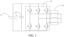
- Oscillating heating is performed on the battery 11 by using the inverter 13 and the motor winding 14.
- the battery 11 is in an alternate charging and discharging state. Therefore, a voltage fluctuation of the battery is large. However, the fluctuation may cause damage to the battery and reduce a service life of the battery.
- Embodiments of the present disclosure provide a battery self-heating system, applied to a vehicle.
- the battery self-heating system includes: a power battery pack 21, a first heating module 22, a second heating module 23, and a controller 24.
- the power battery pack 21 includes a first battery pack E1 and a second battery pack E2 connected in series.
- the first heating module 22 includes a first heating sub-module 221 and a second heating sub-module 222, a first connection end and a second connection end of the first heating sub-module 221 are respectively connected to positive and negative electrodes of the first battery pack E1, a first connection end and a second connection end of the second heating sub-module 222 are respectively connected to the positive and negative electrodes of the first battery pack E1, and a third connection end of the first heating sub-module 221 is connected to a third connection end of the second heating sub-module 222.
- the second heating module 23 includes a third heating sub-module 231 and a fourth heating sub-module 232, a first connection end and a second connection end of the third heating sub-module 231 are respectively connected to positive and negative electrodes of the second battery pack E2, a first connection end and a second connection end of the fourth heating sub-module 232 are respectively connected to the positive and negative electrodes of the second battery pack E2, and a third connection end of the third heating sub-module 231 is connected to a third connection end of the fourth heating sub-module 232.
- the controller 24 is connected to the first heating module 22 and the second heating module 23.
- the controller 24 is configured to: control the first heating module 22 and the first battery pack E1 to be alternately charged and discharged, control the second heating module 23 and the second battery pack E2 to be alternately charged and discharged, and control one of the first battery pack E1 and the second battery pack E2 to be in a charging state when the other of the first battery pack E1 and the second battery pack E2 is in a discharging state.
- a voltage fluctuation of the first battery pack and a voltage fluctuation of the second battery pack offset each other, so that a terminal voltage fluctuation of the power battery pack is small, thereby avoiding charging failure of the vehicle.
- the first upper switch 321 is connected to the positive electrode of the first battery pack E1
- the first lower switch 322 is connected to the negative electrode of the first battery pack E1
- a first end of the first heating winding 31 is connected to a connection point between the first upper switch 321 and the first lower switch 322
- a second end of the first heating winding 31 is connected to a first end of the second heating winding 33
- a second end of the second heating winding 33 is connected to a connection point between the second upper switch 341 and the second lower switch 342
- the second upper switch 341 is connected to the positive electrode of the first battery pack E1
- the second lower switch 342 is connected to the negative electrode of the first battery pack E1.
- the third heating sub-module 231 includes a third heating winding 35 and a third switch 36
- the fourth heating sub-module 232 includes a fourth heating winding 37 and a fourth switch 38
- the third switch 36 includes a third upper switch 361 and a third lower switch 362 connected in series
- the fourth switch 38 includes a fourth upper switch 381 and a fourth lower switch 382 connected in series.
- the third upper switch 361 is connected to the positive electrode of the second battery pack E2
- the third lower switch 362 is connected to the negative electrode of the second battery pack E2
- a first end of the third heating winding 35 is connected to a connection point between the third upper switch 361 and the third lower switch 362
- a second end of the third heating winding 35 is connected to a first end of the fourth heating winding 37
- a second end of the fourth heating winding 37 is connected to a connection point between the fourth upper switch 381 and the fourth lower switch 382
- the fourth upper switch 381 is connected to the positive electrode of the second battery pack E2
- the fourth lower switch 382 is connected to the negative electrode of the second battery pack E2.
- self-heating may be performed on a power battery pack by using multiple drive motor controllers and multiple drive motors in the vehicle.
- a vehicle with multiple three-phase motors is used as an example.
- a power battery pack is divided into two battery packs, and four groups of drive motor controllers and drive motors are selected.
- a drive motor controller and a drive motor in one group are respectively used as a first switch and a first heating winding of a first heating sub-module.
- a drive motor controller and a drive motor in one group are respectively used as a second switch and a second heating winding of a second heating sub-module.
- a drive motor controller and a drive motor in one group are respectively used as a third switch and a third heating winding of a third heating sub-module.
- a drive motor controller and a drive motor in one group are respectively used as a fourth switch and a fourth heating winding of a fourth heating sub-module.
- the first heating winding is a multiphase winding in a first drive motor 1 of the vehicle
- the first switch is a first multiphase inverter in a first drive motor controller 2 corresponding to the first drive motor 1
- the first upper switch represents an upper bridge arm of the first multiphase inverter
- the first lower switch represents a lower bridge arm of the first multiphase inverter.
- the second heating winding is a multiphase winding in a second drive motor 3 of the vehicle
- the second switch is a second multiphase inverter in a second drive motor controller 4 corresponding to the second drive motor 3
- the second upper switch represents an upper bridge arm of the second multiphase inverter
- the second lower switch represents a lower bridge arm of the second multiphase inverter.
- the third heating winding is a multiphase winding in a third drive motor 5 of the vehicle
- the third switch is a third multiphase inverter in a third drive motor controller 6 corresponding to the third drive motor 5
- the third upper switch represents an upper bridge arm of the third multiphase inverter
- the third lower switch represents a lower bridge arm of the third multiphase inverter.
- the fourth heating winding is a multiphase winding in a fourth drive motor 7 of the vehicle
- the fourth switch is a fourth multiphase inverter in a fourth drive motor controller 8 corresponding to the fourth drive motor 7
- the fourth upper switch represents an upper bridge arm of the fourth multiphase inverter
- the fourth lower switch represents a lower bridge arm of the fourth multiphase inverter.
- the controller is configured to: in a first preset state, control the upper bridge arm of the first multiphase inverter to turn on and control the lower bridge arm of the second multiphase inverter to turn on, to control the first battery pack to discharge to charge the first heating winding and the second heating winding, and control the lower bridge arm of the third multiphase inverter to turn on and control the upper bridge arm of the fourth multiphase inverter to turn on, to control the first heating winding and the second heating winding to charge the second battery pack.
- controller is configured to: in a second preset state, control the lower bridge arm of the first multiphase inverter to turn on and control the upper bridge arm of the second multiphase inverter to turn on, to control the first heating winding and the second heating winding to charge the first battery pack, and control the upper bridge arm of the third multiphase inverter to turn on and control the lower bridge arm of the fourth multiphase inverter to turn on, to control the second battery pack to discharge to charge the first heating winding and the second heating winding.
- the upper bridge arm of the first drive motor controller 2 is turned on, and the lower bridge arm of the first drive motor controller 2 is turned off.
- the upper bridge arm of the second drive motor controller 4 is turned off, and the lower bridge arm of the second drive motor controller 4 is turned on.
- the first battery pack E1 charges the multiphase winding in the first drive motor 1 through the upper bridge arm of the first drive motor controller 2.
- a charging current flows through the second drive motor 3, to charge the multiphase winding in the second drive motor 3, and the charging current finally flows back to first battery pack E1 through the lower bridge arm of the second drive motor controller 4.
- the first battery pack E1 is discharged, and a voltage drops.
- the upper bridge arm of the first drive motor controller 2 is turned off, and the lower bridge arm of the first drive motor controller 2 is turned on or turned off.
- the upper bridge arm of the second drive motor controller 4 is turned on or turned off, and the lower bridge arm of the second drive motor controller 4 is turned off.
- the multiphase winding in the first drive motor 1 and the multiphase winding in the second drive motor 3 charge, through the upper bridge arm of the second drive motor controller 4, the first battery pack E1 by using stored energy. In this case, the first battery pack E1 is charged, and a voltage rises.
- the upper bridge arm of the third drive motor controller 6 is turned on, and the lower bridge arm of the third drive motor controller 6 is turned off.
- a voltage of the first battery pack E1 continues to drop, and a drop range ⁇ U 1 is equal to I 1 ⁇ Rcell 1 .
- a voltage of the second battery pack E2 continues to rise, and a rise range ⁇ U 2 is equal to I 2 ⁇ Rcell 2 .
- a voltage of the first battery pack E1 continues to rise, and a rise range ⁇ U 1 is equal to I 1 ⁇ Rcell 1 .
- a voltage of the second battery pack E2 continues to drop, and a drop range ⁇ U 2 is equal to I 2 ⁇ Rcell 2 .
- the controller is further configured to: in a same preset state, control a ratio of a value of a current flowing through the first battery pack to a value of a current flowing through the second battery pack to be equal to a ratio of a resistance value of the second battery pack to a resistance value of the first battery pack.
- the first changeover switch K1 is arranged on a connection circuit of the first heating winding (the multiphase winding in the first drive motor 1) and the second heating winding (the multiphase winding in the second drive motor 3).
- the second changeover switch K2 is arranged on a connection circuit of the third heating winding (the multiphase winding in the third drive motor 5) and the fourth heating winding (the multiphase winding in the fourth drive motor 7).
- embodiments of the present disclosure further provide a vehicle, including the foregoing battery self-heating system.
- a battery in the vehicle is heated and a temperature is increased, to ensure performance of the battery in a low-temperature environment.
- self-heating can also be performed on a power battery pack.
Landscapes
- Engineering & Computer Science (AREA)
- Power Engineering (AREA)
- Transportation (AREA)
- Mechanical Engineering (AREA)
- Manufacturing & Machinery (AREA)
- General Chemical & Material Sciences (AREA)
- Electrochemistry (AREA)
- Chemical Kinetics & Catalysis (AREA)
- Chemical & Material Sciences (AREA)
- Life Sciences & Earth Sciences (AREA)
- Sustainable Energy (AREA)
- Sustainable Development (AREA)
- Automation & Control Theory (AREA)
- Electromagnetism (AREA)
- Physics & Mathematics (AREA)
- Electric Propulsion And Braking For Vehicles (AREA)
- Charge And Discharge Circuits For Batteries Or The Like (AREA)
- Secondary Cells (AREA)
- Inverter Devices (AREA)
Abstract
Description
- The present disclosure claims priority to
Chinese Patent Application No. 202211071491.X, filed on August 31, 2022 - The present disclosure relates to an electric vehicle technology, and specifically, to a battery self-heating system and a vehicle.
- In response to energy conservation and emission reduction, more and more electric vehicles are coming into the public eye. When an electric vehicle is in a low-temperature environment, the activity of positive and negative electrode materials of a battery and the activity of an electrolyte solution in the battery are reduced due to low temperatures, and the charging and discharging performance of the battery is greatly reduced. To ensure the power of the electric vehicle in a low-temperature environment, the battery of the electric vehicle may be heated, to cause a temperature of a battery body of the electric vehicle to increase, so as to ensure the charging and discharging performance of the battery. In the related art, battery heating is implemented through alternate charging and discharging between a battery pack and an energy storage element. However, in a current charging and discharging process, terminal voltage fluctuation of the battery pack is large.
- An objective of the present disclosure is to provide a battery self-heating system and a vehicle, to resolve the foregoing technical problem.
- To implement the foregoing objective, a first aspect of the present disclosure provides a battery self-heating system, applied to a vehicle. The system includes:
- a power battery pack, the power battery pack including a first battery pack and a second battery pack connected in series;
- a first heating module, the first heating module including a first heating sub-module and a second heating sub-module, a first connection end and a second connection end of the first heating sub-module being respectively connected to positive and negative electrodes of the first battery pack, a first connection end and a second connection end of the second heating sub-module being respectively connected to the positive and negative electrodes of the first battery pack, and a third connection end of the first heating sub-module being connected to a third connection end of the second heating sub-module;
- a second heating module, the second heating module including a third heating sub-module and a fourth heating sub-module, a first connection end and a second connection end of the third heating sub-module being respectively connected to positive and negative electrodes of the second battery pack, a first connection end and a second connection end of the fourth heating sub-module being respectively connected to the positive and negative electrodes of the second battery pack, and a third connection end of the third heating sub-module being connected to a third connection end of the fourth heating sub-module; and
- a controller, connected to the first heating module and the second heating module, the controller being configured to: control the first heating module and the first battery pack to alternately charge and discharge, control the second heating module and the second battery pack to alternately charge and discharge, and control one of the first battery pack and the second battery pack to be in a charging state when the other of the first battery pack and the second battery pack is in a discharging state.
- Optionally, the first heating sub-module includes a first heating winding and a first switch, the second heating sub-module includes a second heating winding and a second switch, the first switch includes a first upper switch and a first lower switch connected in series, and the second switch includes a second upper switch and a second lower switch connected in series. The first upper switch is connected to the positive electrode of the first battery pack, the first lower switch is connected to the negative electrode of the first battery pack, a first end of the first heating winding is connected to a connection point between the first upper switch and the first lower switch, a second end of the first heating winding is connected to a first end of the second heating winding, a second end of the second heating winding is connected to a connection point between the second upper switch and the second lower switch, the second upper switch is connected to the positive electrode of the first battery pack, and the second lower switch is connected to the negative electrode of the first battery pack.
- The third heating sub-module includes a third heating winding and a third switch, the fourth heating sub-module includes a fourth heating winding and a fourth switch, the third switch includes a third upper switch and a third lower switch connected in series, and the fourth switch includes a fourth upper switch and a fourth lower switch connected in series. The third upper switch is connected to the positive electrode of the second battery pack, the third lower switch is connected to the negative electrode of the second battery pack, a first end of the third heating winding is connected to a connection point between the third upper switch and the third lower switch, a second end of the third heating winding is connected to a first end of the fourth heating winding, a second end of the fourth heating winding is connected to a connection point between the fourth upper switch and the fourth lower switch, the fourth upper switch is connected to the positive electrode of the second battery pack, and the fourth lower switch is connected to the negative electrode of the second battery pack.
- Optionally, the first heating winding is a multiphase winding in a first drive motor of the vehicle, the first switch is a first multiphase inverter in a first drive motor controller corresponding to the first drive motor, the first upper switch represents an upper bridge arm of the first multiphase inverter, and the first lower switch represents a lower bridge arm of the first multiphase inverter.
- The second heating winding is a multiphase winding in a second drive motor of the vehicle, the second switch is a second multiphase inverter in a second drive motor controller corresponding to the second drive motor, the second upper switch represents an upper bridge arm of the second multiphase inverter, and the second lower switch represents a lower bridge arm of the second multiphase inverter.
- The third heating winding is a multiphase winding in a third drive motor of the vehicle, the third switch is a third multiphase inverter in a third drive motor controller corresponding to the third drive motor, the third upper switch represents an upper bridge arm of the third multiphase inverter, and the third lower switch represents a lower bridge arm of the third multiphase inverter.
- The fourth heating winding is a multiphase winding in a fourth drive motor of the vehicle, the fourth switch is a fourth multiphase inverter in a fourth drive motor controller corresponding to the fourth drive motor, the fourth upper switch represents an upper bridge arm of the fourth multiphase inverter, and the fourth lower switch represents a lower bridge arm of the fourth multiphase inverter.
- Optionally, the controller is configured to: in a first preset state, control the upper bridge arm of the first multiphase inverter to turn on and control the lower bridge arm of the second multiphase inverter to turn on, to control the first battery pack to discharge to charge the first heating winding and the second heating winding, and control the lower bridge arm of the third multiphase inverter to turn on and control the upper bridge arm of the fourth multiphase inverter to turn on, to control the first heating winding and the second heating winding to charge the second battery pack.
- The controller is configured to: in a second preset state, control the lower bridge arm of the first multiphase inverter to turn on and control the upper bridge arm of the second multiphase inverter to turn on, to control the first heating winding and the second heating winding to charge the first battery pack, and control the upper bridge arm of the third multiphase inverter to turn on and control the lower bridge arm of the fourth multiphase inverter to turn on, to control the second battery pack to discharge to charge the first heating winding and the second heating winding.
- Optionally, the controller is further configured to: in a same preset state, control a ratio of a value of a current flowing through the first battery pack to a value of a current flowing through the second battery pack to be equal to a ratio of a resistance value of the second battery pack to a resistance value of the first battery pack.
- Optionally, the system further includes: a first changeover switch, a second changeover switch, a third changeover switch, and a fourth changeover switch. Both the third changeover switch and the fourth changeover switch are dual-position switches.
- The first changeover switch is arranged on a connection circuit of the first heating winding and the second heating winding.
- The second changeover switch is arranged on a connection circuit of the third heating winding and the fourth heating winding.
- A fixed contact of the third changeover switch is connected to a connection end between the lower bridge arm of the first multiphase inverter and the lower bridge arm of the second multiphase inverter, a first moving contact of the third changeover switch is separately connected to a negative electrode end of the first battery pack and a positive electrode end of the second battery pack, and a second moving contact of the third changeover switch is connected to a negative electrode end of the second battery pack.
- A fixed contact of the fourth changeover switch is connected to a connection end between the upper bridge arm of the third multiphase inverter and the upper bridge arm of the fourth multiphase inverter, a first moving contact of the fourth changeover switch is connected to a positive electrode end of the first battery pack, and a second moving contact of the fourth changeover switch is separately connected to the negative electrode end of the first battery pack and the positive electrode end of the second battery pack.
- The first changeover switch, the second changeover switch, the third changeover switch, and the fourth changeover switch are connected to the controller, and the controller is configured to: control the first changeover switch and the second changeover switch to turn on, control the fixed contact of the third changeover switch to connect to the first moving contact of the third changeover switch, and control the fixed contact of the fourth changeover switch to connect to the second moving contact of the fourth changeover switch, to implement self-heating of the first battery pack and the second battery pack.
- Optionally, the controller is further configured to: control the first changeover switch and the second changeover switch to turn off, control the fixed contact of the third changeover switch to connect to the second moving contact of the third changeover switch, and control the fixed contact of the fourth changeover switch to connect to the first moving contact of the fourth changeover switch, to control the first battery pack and the second battery pack to supply power to the first drive motor, the second drive motor, the third drive motor, and the fourth drive motor to drive the vehicle.
- Optionally, the system further includes a first charging switch and a second charging switch.
- The first charging switch is arranged on a connection circuit of a charging port of the vehicle and the positive electrode of the first battery pack.
- The second charging switch is arranged on a connection circuit of the charging port of the vehicle and the negative electrode of the second battery pack.
- The controller is further configured to: when the vehicle is connected to a charging pile, control the first charging switch and the second charging switch to turn on, to charge the power battery pack while implementing the self-heating of the first battery pack and the second battery pack.
- Optionally, the controller is further configured to: when the vehicle is connected to the charging pile, control the first charging switch and the second charging switch to turn on, and control the third changeover switch and the fourth changeover switch to turn off, to separately charge the power battery pack.
- A second aspect of the present disclosure further provides a vehicle, including the battery self-heating system according to any one in the foregoing first aspect.
- A battery self-heating system provided in the present disclosure is applied to a vehicle. The system includes a power battery pack, a drive module, a first heating module, a second heating module, and a controller. The first heating module and a first battery pack are alternately charged and discharged, the second heating module and a second battery pack are alternately charged and discharged, and one of the first battery pack and the second battery pack is in a charging state when the other of the first battery pack and the second battery pack is in a discharging state. In this way, a voltage fluctuation of the first battery pack and a voltage fluctuation of the second battery pack during self-heating offset each other, so that a terminal voltage fluctuation of the power battery pack is small, thereby avoiding charging failure of the vehicle.
- Other features and advantages of the present disclosure are to be described in detail in subsequent specific implementations.
- The accompanying drawings are used for providing a further understanding of the present disclosure and constitute a part of the specification, and are used for explaining the present disclosure together with specific implementations below, but are not intended to limit the present disclosure. In the accompanying drawings:
-
FIG. 1 is a schematic diagram of a battery self-heating circuit in the related art; -
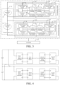
FIG. 2 is a schematic diagram of a battery self-heating system according to an embodiment of the present disclosure; -
FIG. 3 is a schematic diagram of another battery self-heating system according to an embodiment of the present disclosure; -
FIG. 4 is a schematic diagram of another battery self-heating system according to an embodiment of the present disclosure; -
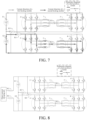
FIG. 5 is a circuit diagram of a battery self-heating system according to an embodiment of the present disclosure; -
FIG. 6 is a schematic diagram of a current direction when a battery self-heating system according to an embodiment of the present disclosure operates; -
FIG. 7 is a schematic diagram of a current direction when another battery self-heating system according to an embodiment of the present disclosure operates; -
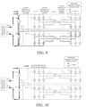
FIG. 8 is a circuit diagram of another battery self-heating system according to an embodiment of the present disclosure; -
FIG. 9 is a schematic diagram of a current direction when another battery self-heating system according to an embodiment of the present disclosure operates; and -
FIG. 10 is a schematic diagram of a current direction when another battery self-heating system according to an embodiment of the present disclosure operates. - The following describes the specific implementations of the present disclosure in detail with reference to the accompanying drawings. It should be understood that the specific implementations described herein are merely used for describing and explaining the present disclosure, and are not intended to limit the present disclosure.
- It should be understood that steps recorded in method implementations in the present disclosure may be performed in different orders, and/or performed in parallel. In addition, the method implementations may include an additional step and/or omit a step that is performed and shown. The scope of the present disclosure is not limited in this aspect. The term "comprise" and its variants used herein mean open inclusion, in other words, "comprising but not limited to". The term "based on" is "at least partially based on". The term "an embodiment" represents "at least one embodiment". The term "another embodiment" represents "at least one another embodiment". The term "some embodiments" represents "at least some embodiments". Related definitions of other terms are described below.
- It is to be noted that, concepts such as "first" and "second" mentioned in the present disclosure are used for distinguishing different apparatuses, modules, or units, and are not used for limiting an order or independent relationship of functions performed by these apparatuses, modules, or units. It is to be noted that, modifiers "one" and "multiple" mentioned in the present disclosure are exemplary instead of limitative. A person skilled in the art should understand that the modifiers should be understood as "one or more", unless the context clearly indicates otherwise.
- In response to energy conservation and emission reduction, more and more electric vehicles are selected by more users. To improve driving performance of the electric vehicles, a multi-motor electric vehicle known for strong power gradually enters the public eye. The strong power requires good charging and discharging performance of a battery. However, when an electric vehicle is in a low-temperature environment, especially in a temperature below - 10 °C, the activity of positive and negative electrode materials of the battery and the activity of electrolyte solutions in the battery are reduced due to the low temperature, and the charging and discharging performance of the battery is greatly reduced. To ensure power of the electric vehicle in the low-temperature environment, the battery of the electric vehicle may be heated, to cause a temperature of a battery body of the electric vehicle to increase, so as to ensure the charging and discharging performance of the battery.
- Currently, the battery may be heated in two manners: external heating and internal heating. In the external heating manner, an additional heating device is added, to heat the battery. In this heating manner, costs are high due to addition of the heating device, and heating efficiency is low because heat dissipation is fast outside and there is a specific distance between a position at which an external temperature is increased and the internal battery. However, a principle of the internal heating manner is mainly to generate heat through an internal resistance of the battery by using the cyclic charging and discharging of the battery. For example, as shown in
FIG. 1 , a battery self-heating circuit includes abattery 11, acapacitor 12, aninverter 13, and a motor winding 14. Thebattery 11, thecapacitor 12, and theinverter 13 are connected in parallel. Oscillating heating is performed on thebattery 11 by using theinverter 13 and the motor winding 14. In addition, during the oscillating heating, thebattery 11 is in an alternate charging and discharging state. Therefore, a voltage fluctuation of the battery is large. However, the fluctuation may cause damage to the battery and reduce a service life of the battery. - In addition, if a charging pile is connected for direct current charging during battery self-heating, the battery is limited by a heating principle of the battery self-heating, to be specific, when a large current flows through the battery, the internal resistance of the battery generates heat, to heat the battery. In other words, to generate a larger amount of heating, a larger self-heating current is required when the internal resistance of the battery and heating time remain unchanged. The voltage fluctuation ΔU of the battery is equal to I×Rcell. In a case that a total internal resistance Rcell of the battery remains unchanged, the larger a battery current I is, the greater the voltage fluctuation ΔU of the battery is. The fluctuation may cause the charging pile to fail to track a battery voltage in real time during direct current charging, resulting in a gun jump or charging failure. In addition, due to a limitation of topology, in currents flowing through a motor winding at a same moment, there are currents flowing in the motor winding and currents flowing out of the motor winding. In other words, a heating current can only be a current limit value of a single-phase winding. As a result, a heating power is limited.
- In view of this, the present disclosure provides a battery self-heating system and a vehicle, to resolve the foregoing problem.
- The technical solution of the present disclosure is described in detail embodiments below.
- Embodiments of the present disclosure provide a battery self-heating system, applied to a vehicle. Referring to
FIG. 2 , the battery self-heating system includes: apower battery pack 21, afirst heating module 22, asecond heating module 23, and acontroller 24. - The
power battery pack 21 includes a first battery pack E1 and a second battery pack E2 connected in series. Thefirst heating module 22 includes afirst heating sub-module 221 and asecond heating sub-module 222, a first connection end and a second connection end of thefirst heating sub-module 221 are respectively connected to positive and negative electrodes of the first battery pack E1, a first connection end and a second connection end of thesecond heating sub-module 222 are respectively connected to the positive and negative electrodes of the first battery pack E1, and a third connection end of thefirst heating sub-module 221 is connected to a third connection end of thesecond heating sub-module 222. Thesecond heating module 23 includes athird heating sub-module 231 and afourth heating sub-module 232, a first connection end and a second connection end of thethird heating sub-module 231 are respectively connected to positive and negative electrodes of the second battery pack E2, a first connection end and a second connection end of thefourth heating sub-module 232 are respectively connected to the positive and negative electrodes of the second battery pack E2, and a third connection end of thethird heating sub-module 231 is connected to a third connection end of thefourth heating sub-module 232. Thecontroller 24 is connected to thefirst heating module 22 and thesecond heating module 23. Thecontroller 24 is configured to: control thefirst heating module 22 and the first battery pack E1 to be alternately charged and discharged, control thesecond heating module 23 and the second battery pack E2 to be alternately charged and discharged, and control one of the first battery pack E1 and the second battery pack E2 to be in a charging state when the other of the first battery pack E1 and the second battery pack E2 is in a discharging state. - When the foregoing battery self-heating system is used for battery self-heating, a voltage fluctuation of the first battery pack and a voltage fluctuation of the second battery pack offset each other, so that a terminal voltage fluctuation of the power battery pack is small, thereby avoiding charging failure of the vehicle.
- To enable a person skilled in the art to better understand the battery self-heating system provided in the present disclosure, the foregoing steps are described in detail with examples below.
- In a possible manner, referring to
FIG. 3 , thefirst heating sub-module 221 includes a first heating winding 31 and afirst switch 32, thesecond heating sub-module 222 includes a second heating winding 33 and asecond switch 34, thefirst switch 32 includes a firstupper switch 321 and a firstlower switch 322 connected in series, and thesecond switch 34 includes a secondupper switch 341 and a secondlower switch 342 connected in series. The firstupper switch 321 is connected to the positive electrode of the first battery pack E1, the firstlower switch 322 is connected to the negative electrode of the first battery pack E1, a first end of the first heating winding 31 is connected to a connection point between the firstupper switch 321 and the firstlower switch 322, a second end of the first heating winding 31 is connected to a first end of the second heating winding 33, a second end of the second heating winding 33 is connected to a connection point between the secondupper switch 341 and the secondlower switch 342, the secondupper switch 341 is connected to the positive electrode of the first battery pack E1, and the secondlower switch 342 is connected to the negative electrode of the first battery pack E1. - In addition, the
third heating sub-module 231 includes a third heating winding 35 and athird switch 36, thefourth heating sub-module 232 includes a fourth heating winding 37 and afourth switch 38, thethird switch 36 includes a thirdupper switch 361 and a third lower switch 362 connected in series, and thefourth switch 38 includes a fourthupper switch 381 and a fourthlower switch 382 connected in series. The thirdupper switch 361 is connected to the positive electrode of the second battery pack E2, the third lower switch 362 is connected to the negative electrode of the second battery pack E2, a first end of the third heating winding 35 is connected to a connection point between the thirdupper switch 361 and the third lower switch 362, a second end of the third heating winding 35 is connected to a first end of the fourth heating winding 37, a second end of the fourth heating winding 37 is connected to a connection point between the fourthupper switch 381 and the fourthlower switch 382, the fourthupper switch 381 is connected to the positive electrode of the second battery pack E2, and the fourthlower switch 382 is connected to the negative electrode of the second battery pack E2. - In a possible manner, for a vehicle with multiple motors, self-heating may be performed on a power battery pack by using multiple drive motor controllers and multiple drive motors in the vehicle. Referring to
FIG. 4 , a vehicle with multiple three-phase motors is used as an example. A power battery pack is divided into two battery packs, and four groups of drive motor controllers and drive motors are selected. A drive motor controller and a drive motor in one group are respectively used as a first switch and a first heating winding of a first heating sub-module. A drive motor controller and a drive motor in one group are respectively used as a second switch and a second heating winding of a second heating sub-module. A drive motor controller and a drive motor in one group are respectively used as a third switch and a third heating winding of a third heating sub-module. A drive motor controller and a drive motor in one group are respectively used as a fourth switch and a fourth heating winding of a fourth heating sub-module. - Referring to
FIG. 5 , the first heating winding is a multiphase winding in a first drive motor 1 of the vehicle, the first switch is a first multiphase inverter in a firstdrive motor controller 2 corresponding to the first drive motor 1, the first upper switch represents an upper bridge arm of the first multiphase inverter, and the first lower switch represents a lower bridge arm of the first multiphase inverter. The second heating winding is a multiphase winding in asecond drive motor 3 of the vehicle, the second switch is a second multiphase inverter in a second drive motor controller 4 corresponding to thesecond drive motor 3, the second upper switch represents an upper bridge arm of the second multiphase inverter, and the second lower switch represents a lower bridge arm of the second multiphase inverter. The third heating winding is a multiphase winding in athird drive motor 5 of the vehicle, the third switch is a third multiphase inverter in a thirddrive motor controller 6 corresponding to thethird drive motor 5, the third upper switch represents an upper bridge arm of the third multiphase inverter, and the third lower switch represents a lower bridge arm of the third multiphase inverter. The fourth heating winding is a multiphase winding in afourth drive motor 7 of the vehicle, the fourth switch is a fourth multiphase inverter in a fourthdrive motor controller 8 corresponding to thefourth drive motor 7, the fourth upper switch represents an upper bridge arm of the fourth multiphase inverter, and the fourth lower switch represents a lower bridge arm of the fourth multiphase inverter. - In a possible manner, the controller is configured to: in a first preset state, control the upper bridge arm of the first multiphase inverter to turn on and control the lower bridge arm of the second multiphase inverter to turn on, to control the first battery pack to discharge to charge the first heating winding and the second heating winding, and control the lower bridge arm of the third multiphase inverter to turn on and control the upper bridge arm of the fourth multiphase inverter to turn on, to control the first heating winding and the second heating winding to charge the second battery pack.
- Further, the controller is configured to: in a second preset state, control the lower bridge arm of the first multiphase inverter to turn on and control the upper bridge arm of the second multiphase inverter to turn on, to control the first heating winding and the second heating winding to charge the first battery pack, and control the upper bridge arm of the third multiphase inverter to turn on and control the lower bridge arm of the fourth multiphase inverter to turn on, to control the second battery pack to discharge to charge the first heating winding and the second heating winding.
- For example, in the first preset state, referring to
FIG. 6 , the upper bridge arm of the firstdrive motor controller 2 is turned on, and the lower bridge arm of the firstdrive motor controller 2 is turned off. The upper bridge arm of the second drive motor controller 4 is turned off, and the lower bridge arm of the second drive motor controller 4 is turned on. The first battery pack E1 charges the multiphase winding in the first drive motor 1 through the upper bridge arm of the firstdrive motor controller 2. A charging current flows through thesecond drive motor 3, to charge the multiphase winding in thesecond drive motor 3, and the charging current finally flows back to first battery pack E1 through the lower bridge arm of the second drive motor controller 4. In this case, the first battery pack E1 is discharged, and a voltage drops. The upper bridge arm of the thirddrive motor controller 6 is turned off, and the lower bridge arm of the thirddrive motor controller 6 is turned on or turned off (according to a feature that a diode is unidirectionally turned on, the current passes through a parasitic diode of the lower bridge arm when the lower bridge arm is turned off, and the same applies below). The upper bridge arm of the fourthdrive motor controller 8 is turned on or turned off, and the lower bridge arm of the fourthdrive motor controller 8 is turned off. The multiphase winding in thethird drive motor 5 and the multiphase winding in thefourth drive motor 7 charge, through the upper bridge arm of the fourthdrive motor controller 8, the second battery pack E2 by using stored energy. In this case, the second battery pack E2 is charged, and a voltage rises. - For example, in the second preset state, referring to
FIG. 7 , the upper bridge arm of the firstdrive motor controller 2 is turned off, and the lower bridge arm of the firstdrive motor controller 2 is turned on or turned off. The upper bridge arm of the second drive motor controller 4 is turned on or turned off, and the lower bridge arm of the second drive motor controller 4 is turned off. The multiphase winding in the first drive motor 1 and the multiphase winding in thesecond drive motor 3 charge, through the upper bridge arm of the second drive motor controller 4, the first battery pack E1 by using stored energy. In this case, the first battery pack E1 is charged, and a voltage rises. The upper bridge arm of the thirddrive motor controller 6 is turned on, and the lower bridge arm of the thirddrive motor controller 6 is turned off. The upper bridge arm of the fourthdrive motor controller 8 is turned off, and the lower bridge arm of the fourthdrive motor controller 8 is turned on. The second battery pack E2 charges the multiphase winding in thethird drive motor 5 through the upper bridge arm of the thirddrive motor controller 6. A charging current flows through thefourth drive motor 7, to charge the multiphase winding in thefourth drive motor 7, and the charging current finally flows back to second battery pack E2 through the lower bridge arm of the fourthdrive motor controller 8. In this case, the second battery pack E2 is discharged, and a voltage drops. - It is worth noting that in the first preset state, a voltage of the first battery pack E1 continues to drop, and a drop range ΔU1 is equal to I1×Rcell1. A voltage of the second battery pack E2 continues to rise, and a rise range ΔU2 is equal to I2×Rcell2. In the second preset state, a voltage of the first battery pack E1 continues to rise, and a rise range ΔU1 is equal to I1×Rcell1. A voltage of the second battery pack E2 continues to drop, and a drop range ΔU2 is equal to I2×Rcell2. Therefore, the current I1 and the resistance Rcell1 of the first battery pack and the current I2 and the resistance Rcell2 of the second battery pack are controlled, so that a total voltage fluctuation of the power battery pack may be within a preset voltage fluctuation range, for example, -0.5 V to 0.5 V. A specific preset voltage fluctuation range may be determined according to a requirement, and this is not limited in the present disclosure. Certainly, on a premise that Rcell1 is equal to Rcell2, as long as it is ensured that I1 is equal to I2, the total voltage fluctuation of the power battery pack may be 0. In this way, by cycling back and forth between the first preset state and the second preset state, energy is cyclically charged and discharged between the power battery pack and a motor winding, thereby implementing battery self-heating.
- In a possible manner, the controller is further configured to: in a same preset state, control a ratio of a value of a current flowing through the first battery pack to a value of a current flowing through the second battery pack to be equal to a ratio of a resistance value of the second battery pack to a resistance value of the first battery pack.
- For example, it may be learned from the foregoing charging and discharging process between the first battery pack and the second battery pack during battery self-heating that, the voltage fluctuation is related with a current and a resistance of the battery. The resistance value of the battery pack is determined when the battery pack is divided. Therefore, the total voltage fluctuation of the power battery pack may be kept within the preset voltage fluctuation range by adjusting the current of the battery pack. For example, if the power battery pack is divided into two battery packs with a same number of battery cores, Rcell1 is equal to Rcell2. If the total voltage fluctuation of the power battery pack needs to be controlled to be 0, a case in which I1 is equal to I2 may be controlled. For another example, the power battery pack is divided into two battery packs with different numbers of battery cores. If the total voltage fluctuation of the power battery pack needs to be controlled to be 0, a case in which I1/I2 is equal to Rcell2/Rcell1 may be controlled. In other words, in a case that the ratio of the value of the current flowing through the first battery pack to the value of the current flowing through the second battery pack is equal to the ratio of the resistance value of the second battery pack to the resistance value of the first battery pack, the total voltage fluctuation of the power battery pack is equal to 0. Correspondingly, if only the total voltage fluctuation of the power battery pack needs to be controlled to be within the preset voltage fluctuation range, the current of the battery pack into which the power battery pack is divided may be controlled based on a control relationship that the larger the resistance of the battery pack, the smaller the current. Details may be determined based on a requirement and a test, and this is not limited in the present disclosure.
- In addition, the power battery pack may alternatively be divided into three battery packs, four battery packs, or the like, and one heating module is assigned to each battery pack. A number of battery packs and a number of battery cores in the battery pack are not limited in the present disclosure, as long as the total voltage fluctuation of the power battery pack is within the preset voltage fluctuation range. For example, a resistance value of each battery core in the power battery pack is equal. Assuming that numbers of battery cores included in the battery packs are respectively N1, N2, N3, ..., and Nn, self-heating currents of the battery packs should meet that I1/I2/I3/.../In is equal to Nn/.../N3/N2/N1. Certainly, each battery pack may alternatively be connected in parallel with multiple heating modules, as long as a sum of currents of the heating modules is controlled to be equal to a current of the battery pack. The currents of the heating modules connected in parallel in the same battery pack may be equal or unequal, and this is not limited in the present disclosure. In addition, compared with the related art in which a heating current can only be a current limit value of a single-phase winding, in the battery self-heating system provided in the embodiments of the present disclosure, due to addition of the drive motor and the drive motor controller, a maximum heating current may be a current limit value of an N-phase winding. For example, for the three-phase drive motor in
FIG. 5 , the maximum heating current is a current limit value of a three-phase winding, which is three times the heating current in the related art, so that efficiency of battery self-heating is improved. - In a possible manner, a switch may be added in a circuit to control on/off of the circuit. Referring to
FIG. 5 , the system further includes: a first changeover switch K1, a second changeover switch K2, a third changeover switch K3, and a fourth changeover switch K4. Both the third changeover switch K3 and the fourth changeover switch K4 are dual-position switches. - The first changeover switch K1 is arranged on a connection circuit of the first heating winding (the multiphase winding in the first drive motor 1) and the second heating winding (the multiphase winding in the second drive motor 3). The second changeover switch K2 is arranged on a connection circuit of the third heating winding (the multiphase winding in the third drive motor 5) and the fourth heating winding (the multiphase winding in the fourth drive motor 7). A fixed contact a of the third changeover switch K3 is connected to a connection end between the lower bridge arm of the first multiphase inverter (in the first drive motor controller 2) and the lower bridge arm of the second multiphase inverter (in the second drive motor controller 4), a first moving contact b of the third changeover switch K3 is separately connected to a negative electrode end of the first battery pack E1 and a positive electrode end of the second battery pack E2, and a second moving contact c of the third changeover switch K3 is connected to a negative electrode end of the second battery pack E2. A fixed contact a of the fourth changeover switch K4 is connected to a connection end between the upper bridge arm of the third multiphase inverter (in the third drive motor controller 6) and the upper bridge arm of the fourth multiphase inverter (in the fourth drive motor controller 8), a first moving contact b of the fourth changeover switch K4 is connected to a positive electrode end of the first battery pack E1, and a second moving contact c of the fourth changeover switch K4 is separately connected to the negative electrode end of the first battery pack E1 and the positive electrode end of the second battery pack E2.
- Further, the first changeover switch K1, the second changeover switch K2, the third changeover switch K3, and the fourth changeover switch K4 are connected to the controller, and the controller is configured to: control the first changeover switch K1 and the second changeover switch K2 to turn on, control the fixed contact a of the third changeover switch K3 to connect to the first moving contact b of the third changeover switch K3, and control the fixed contact a of the fourth changeover switch K4 to connect to the second moving contact c of the fourth changeover switch K4, to implement self-heating of the first battery pack E1 and the second battery pack E2. For details, refer to
FIG. 6 andFIG. 7 . - In a possible manner, the controller is further configured to: control the first changeover switch K1 and the second changeover switch K2 to turn off, control the fixed contact a of the third changeover switch K3 to connect to the second moving contact c of the third changeover switch K3, and control the fixed contact a of the fourth changeover switch K4 to connect to the first moving contact b of the fourth changeover switch K4, to control the first battery pack E1 and the second battery pack E2 to supply power to the first drive motor, the second drive motor, the third drive motor, and the fourth drive motor to drive the vehicle.
- For example, the first changeover switch K1 and the second changeover switch K2 are controlled to turn off, the fixed contact a of the third changeover switch K3 is controlled to connect to the second moving contact c of the third changeover switch K3, and the fixed contact a of the fourth changeover switch K4 is controlled to connect to the first moving contact b of the fourth changeover switch K4. In this case, the first drive motor and the first drive motor controller, the second drive motor and the second drive motor controller, the third drive motor and the third drive motor controller, and the fourth drive motor and the fourth drive motor controller each form drive modules and are separately connected to the power battery pack in parallel. For an operating process of the drive motor and the drive motor controller in a drive mode, refer to the related art, and details are not described in the present disclosure again.
- In a possible manner, the system further includes a first charging switch K5 and a second charging switch K6. The first charging switch K5 is arranged on a connection circuit of a charging port of the vehicle and the positive electrode of the first battery pack E1, and the second charging switch K6 is arranged on a connection circuit of the charging port of the vehicle and the negative electrode of the second battery pack E2. The controller is further configured to: when the vehicle is connected to a charging pile, control the first charging switch K5 and the second charging switch K6 to turn on, to charge the power battery pack while implementing the self-heating of the first battery pack E1 and the second battery pack E2.
- For example, when the vehicle needs direct current charging and performs battery self-heating, the first charging switch K5, the second charging switch K6, the first changeover switch K1, and the second changeover switch K2 are controlled to turn on, the fixed contact a of the third changeover switch K3 is controlled to connect to the first moving contact b of the third changeover switch K3, and the fixed contact a of the fourth changeover switch K3 is controlled to connect to the second moving contact c of the fourth changeover switch K3.
FIG. 9 shows bridge arm statuses and current directions of the first heating module and the second heating module in the first preset state, and the current direction of direct current charging. For bridge arm statuses and current directions of the first heating module and the second heating module in the second preset state, refer toFIG. 7 , and details are not described in the present disclosure again. In this way, the power battery pack is charged while the self-heating of the first battery pack E1 and the second battery pack E2 is implemented. A voltage fluctuation of the first battery pack and a voltage fluctuation of the second battery pack offset each other, so that a terminal voltage fluctuation of the power battery pack is small, thereby avoiding charging failure of the vehicle. - In a possible manner, the controller is further configured to: when the vehicle is connected to the charging pile, control the first charging switch and the second charging switch to turn on, and control the third changeover switch and the fourth changeover switch to turn off, to separately charge the power battery pack.
- For example, referring to
FIG. 10 , when the vehicle needs direct current charging, the first charging switch K5, the second charging switch K6, the first changeover switch K1, and the second changeover switch K2 are controlled to turn off or turned on, the fixed contact a of the third changeover switch K3 is controlled to be not connected to the first moving contact b and the second moving contact c of the third changeover switch K3, and the fixed contact a of the fourth changeover switch K4 is controlled to be not connected to the first moving contact b and the second moving contact c of the fourth changeover switch K4. - It is worth noting that some drive motor controllers and drive motors in a multi-motor vehicle are used as heating modules to perform self-heating on the power battery pack. In other words, the drive motor controller and the drive motor may be configured to drive the vehicle, and may also be configured to perform self-heating on the power battery pack, without adding another element or heating apparatus, thereby meeting a requirement of heating the power battery pack and reducing costs. However, for another single-motor vehicle or dual-motor vehicle, a self-heating function of the power battery pack may be implemented by adding a switch and a winding as heating modules. Certainly, for the multi-motor vehicle, a switch and a winding may also be added as the heating modules. This is not limited in the present disclosure.
- For example, the switch may be formed by a single-phase bridge arm or a multiphase bridge arm, or may be formed by another switch element having a function of turning on and turning off a circuit. The winding may be a separate single-phase winding or a multiphase winding, or may be a winding in a single-phase motor or a multiphase motor. This is not limited in the present disclosure. In addition, multiple heating modules may be connected to a same battery pack, and each heating module has a same bridge arm status and current direction in a same preset state. In addition, for a heating module that does not participate in driving the vehicle, a six-phase bridge arm and a six-phase motor may be used to replace the two three-phase bridge arms and the two three-phase motors shown in
FIG. 5 . - It is to be noted that the controller may be a control unit in the drive motor controller or an electronic device mounted in the vehicle. This is not limited in the present disclosure. A temperature sensor may also be arranged near the power battery pack, to transmit a collected battery temperature to the controller in real time. When the battery temperature is lower than a preset threshold, the controller automatically controls the power battery pack to perform self-heating. A heating button may also be set on the vehicle. For example, a vehicle-mounted display screen reminds a driver that the power battery pack is in a low-temperature state. Through the heating button set on the vehicle-mounted display screen, the driver may send a signal of starting self-heating to the controller. After receiving the signal, the controller controls the power battery pack to perform self-heating. This is not limited in the present disclosure.
- In addition, in a process of controlling the battery pack to be alternately charged and discharged, one or more of the multiple bridge arms or switches may be controlled to turn on, thereby controlling a number of windings involved in self-heating. For example, in
FIG. 6 , one of the three upper bridge arms of the firstdrive motor controller 2 may be selected to turn on, so that the first battery pack E1 is discharged to charge a winding connected to the first battery pack in the first drive motor 1. Generally, the greater the number of windings involved in self-heating, the higher the efficiency of self-heating. In other possible implementations, the number of windings involved in self-heating may be controlled according to the battery temperature. For example, the lower the battery temperature, the greater the number of windings. This is not limited in the present disclosure. - Based on the same inventive concept, embodiments of the present disclosure further provide a vehicle, including the foregoing battery self-heating system. Through the battery self-heating system, a battery in the vehicle is heated and a temperature is increased, to ensure performance of the battery in a low-temperature environment. In addition, when direct current charging is performed on the vehicle, self-heating can also be performed on a power battery pack.
- The preferred implementations of the present disclosure are described in detail above with reference to the accompanying drawings. However, the present disclosure is not limited to the specific details in the foregoing implementations, multiple simple deformations may be made to the technical solution of the present disclosure within a range of the technical concept of the present disclosure, and these simple deformations fall within the protection scope of the present disclosure.
- In addition, it is to be noted that, the specific technical features described in the above specific implementations may be combined in any suitable manner without contradiction. To avoid unnecessary repetition, various possible combinations are not further described in the present disclosure.
- In addition, different implementations of the present disclosure may also be arbitrarily combined without departing from the idea of the present disclosure, and these combinations shall still be regarded as content disclosed in the present disclosure.
Claims (10)
- A battery self-heating system, applied to a vehicle, the system comprising:a power battery pack (21), the power battery pack (21) comprising a first battery pack (E1) and a second battery pack (E2) connected in series;a first heating module (22), the first heating module (22) comprising a first heating sub-module (221) and a second heating sub-module (222), a first connection end and a second connection end of the first heating sub-module (221) being respectively connected to positive and negative electrodes of the first battery pack (E1), a first connection end and a second connection end of the second heating sub-module (222) being respectively connected to the positive and negative electrodes of the first battery pack (E1), and a third connection end of the first heating sub-module (221) being connected to a third connection end of the second heating sub-module (222);a second heating module (23), the second heating module (23) comprising a third heating sub-module (231) and a fourth heating sub-module (232), a first connection end and a second connection end of the third heating sub-module (231) being respectively connected to positive and negative electrodes of the second battery pack (E2), a first connection end and a second connection end of the fourth heating sub-module being respectively connected to the positive and negative electrodes of the second battery pack (E2), and a third connection end of the third heating sub-module (231) being connected to a third connection end of the fourth heating sub-module (232); anda controller (24), connected to the first heating module (22) and the second heating module (23), the controller (24) being configured to: control the first heating module (22) and the first battery pack (E1) to alternately charge and discharge, control the second heating module (23) and the second battery pack (E2) to alternately charge and discharge, and control one of the first battery pack (E1) and the second battery pack (E2) to be in a charging state when the other of the first battery pack (E1) and the second battery pack (E2) is in a discharging state.
- The system according to claim 1, wherein the first heating sub-module (221) comprises a first heating winding (31) and a first switch (32), the second heating sub-module (222) comprises a second heating winding (33) and a second switch (34), the first switch (32) comprises a first upper switch (321) and a first lower switch (322) connected in series, and the second switch (34) comprises a second upper switch (341) and a second lower switch (342) connected in series, wherein the first upper switch (321) is connected to the positive electrode of the first battery pack (E1), the first lower switch (322) is connected to the negative electrode of the first battery pack (E1), a first end of the first heating winding (31) is connected to a connection point between the first upper switch (321) and the first lower switch (322), a second end of the first heating winding (31) is connected to a first end of the second heating winding (33), a second end of the second heating winding (33) is connected to a connection point between the second upper switch (341) and the second lower switch (342), the second upper switch (341) is connected to the positive electrode of the first battery pack (E1), and the second lower switch (342) is connected to the negative electrode of the first battery pack (E1); and
the third heating sub-module (231) comprises a third heating winding (35) and a third switch (36), the fourth heating sub-module (232) comprises a fourth heating winding (37) and a fourth switch (38), the third switch (36) comprises a third upper switch (361) and a third lower switch (362) connected in series, and the fourth switch (38) comprises a fourth upper switch (381) and a fourth lower switch (382) connected in series, wherein the third upper switch (361) is connected to the positive electrode of the second battery pack (E2), the third lower switch (362) is connected to the negative electrode of the second battery pack (E2), a first end of the third heating winding (35) is connected to a connection point between the third upper switch (361) and the third lower switch (362), a second end of the third heating winding (35) is connected to a first end of the fourth heating winding (37), a second end of the fourth heating winding (37) is connected to a connection point between the fourth upper switch (381) and the fourth lower switch (382), the fourth upper switch (381) is connected to the positive electrode of the second battery pack (E2), and the fourth lower switch (382) is connected to the negative electrode of the second battery pack (E2). - The system according to claim 2, wherein the first heating winding (31) is a multiphase winding in a first drive motor (1) of the vehicle, the first switch (32) is a first multiphase inverter in a first drive motor controller (2) corresponding to the first drive motor (1), the first upper switch (321) represents an upper bridge arm of the first multiphase inverter, and the first lower switch (322) represents a lower bridge arm of the first multiphase inverter;the second heating winding (33) is a multiphase winding in a second drive motor (3) of the vehicle, the second switch (34) is a second multiphase inverter in a second drive motor controller (4) corresponding to the second drive motor (3), the second upper switch (341) represents an upper bridge arm of the second multiphase inverter, and the second lower switch (342) represents a lower bridge arm of the second multiphase inverter;the third heating winding (35) is a multiphase winding in a third drive motor (5) of the vehicle, the third switch (36) is a third multiphase inverter in a third drive motor controller (6) corresponding to the third drive motor (5), the third upper switch (361) represents an upper bridge arm of the third multiphase inverter, and the third lower switch (362) represents a lower bridge arm of the third multiphase inverter; andthe fourth heating winding (37) is a multiphase winding in a fourth drive motor (7) of the vehicle, the fourth switch (38) is a fourth multiphase inverter in a fourth drive motor controller (8) corresponding to the fourth drive motor (7), the fourth upper switch (381) represents an upper bridge arm of the fourth multiphase inverter, and the fourth lower switch (382) represents a lower bridge arm of the fourth multiphase inverter.
- The system according to claim 3, whereinthe controller (24) is configured to: in a first preset state, control the upper bridge arm of the first multiphase inverter to turn on and control the lower bridge arm of the second multiphase inverter to turn on, to control the first battery pack (E1) to discharge to charge the first heating winding (31) and the second heating winding (33), and control the lower bridge arm of the third multiphase inverter to turn on and control the upper bridge arm of the fourth multiphase inverter to turn on, to control the first heating winding (31) and the second heating winding (33) to charge the second battery pack (E2); andthe controller (24) is configured to: in a second preset state, control the lower bridge arm of the first multiphase inverter to turn on and control the upper bridge arm of the second multiphase inverter to turn on, to control the first heating winding (31) and the second heating winding (33) to charge the first battery pack (E1), and control the upper bridge arm of the third multiphase inverter to turn on and control the lower bridge arm of the fourth multiphase inverter to turn on, to control the second battery pack (E2) to discharge to charge the first heating winding (31) and the second heating winding (33).
- The system according to claim 4, wherein the controller (24) is further configured to:
in a same preset state, control a ratio of a value of a current flowing through the first battery pack (E1) to a value of a current flowing through the second battery pack (E2) to be equal to a ratio of a resistance value of the second battery pack (E2) to a resistance value of the first battery pack (E1). - The system according to claim 3, the system further comprising: a first changeover switch (K1), a second changeover switch (K2), a third changeover switch (K3), and a fourth changeover switch (K4), both the third changeover switch (K3) and the fourth changeover switch (K4) being dual-position switches;the first changeover switch (K1) being arranged on a connection circuit of the first heating winding (31) and the second heating winding (33);the second changeover switch (K2) being arranged on a connection circuit of the third heating winding (35) and the fourth heating winding (37);a fixed contact of the third changeover switch (K3) being connected to a connection end between the lower bridge arm of the first multiphase inverter and the lower bridge arm of the second multiphase inverter, a first moving contact of the third changeover switch (K3) being separately connected to a negative electrode end of the first battery pack (E1) and a positive electrode end of the second battery pack (E2), and a second moving contact of the third changeover switch (K3) being connected to a negative electrode end of the second battery pack (E2);a fixed contact of the fourth changeover switch (K4) being connected to a connection end between the upper bridge arm of the third multiphase inverter and the upper bridge arm of the fourth multiphase inverter, a first moving contact of the fourth changeover switch (K4) being connected to a positive electrode end of the first battery pack (E1), and a second moving contact of the fourth changeover switch (K4) being separately connected to the negative electrode end of the first battery pack (E1) and the positive electrode end of the second battery pack (E2); andthe first changeover switch (K1), the second changeover switch (K2), the third changeover switch (K3), and the fourth changeover switch (K4) being connected to the controller (24), and the controller (24) being configured to: control the first changeover switch (K1) and the second changeover switch (K2) to turn on, control the fixed contact of the third changeover switch (K3) to connect to the first moving contact of the third changeover switch (K3), and control the fixed contact of the fourth changeover switch (K4) to connect to the second moving contact of the fourth changeover switch (K4), to implement self-heating of the first battery pack (E1) and the second battery pack (E2).
- The system according to claim 6, wherein the controller (24) is further configured to: control the first changeover switch (K1) and the second changeover switch (K2) to turn off, control the fixed contact of the third changeover switch (K3) to connect to the second moving contact of the third changeover switch (K3), and control the fixed contact of the fourth changeover switch (K4) to connect to the first moving contact of the fourth changeover switch (K4), to control the first battery pack (E1) and the second battery pack (E2) to supply power to the first drive motor (1), the second drive motor (3), the third drive motor (5), and the fourth drive motor (7) to drive the vehicle.
- The system according to claim 6, further comprising a first charging switch (K5) and a second charging switch (K6);the first charging switch (K5) being arranged on a connection circuit of a charging port of the vehicle and the positive electrode of the first battery pack (E1);the second charging switch (K6) being arranged on a connection circuit of the charging port of the vehicle and the negative electrode of the second battery pack (E2); andthe controller (24) being further configured to: when the vehicle is connected to a charging pile, control the first charging switch (K5) and the second charging switch (K6) to turn on, to charge the power battery pack (21) while implementing the self-heating of the first battery pack (E1) and the second battery pack (E2).
- The system according to claim 8, wherein
the controller (24) is further configured to: when the vehicle is connected to the charging pile, control the first charging switch (K5) and the second charging switch (K6) to turn on, and control the third changeover switch (K3) and the fourth changeover switch (K4) to turn off, to separately charge the power battery pack (21). - A vehicle, comprising the battery self-heating system according to any one of claims 1 to 9.
Applications Claiming Priority (2)
| Application Number | Priority Date | Filing Date | Title |
|---|---|---|---|
| CN202211071491.XA CN117656951B (en) | 2022-08-31 | 2022-08-31 | Battery self-heating system and vehicle |
| PCT/CN2023/090701 WO2024045657A1 (en) | 2022-08-31 | 2023-04-25 | Battery self-heating system and vehicle |
Publications (2)
| Publication Number | Publication Date |
|---|---|
| EP4582306A1 true EP4582306A1 (en) | 2025-07-09 |
| EP4582306A4 EP4582306A4 (en) | 2025-11-12 |
Family
ID=90073966
Family Applications (1)
| Application Number | Title | Priority Date | Filing Date |
|---|---|---|---|
| EP23858697.8A Pending EP4582306A4 (en) | 2022-08-31 | 2023-04-25 | Battery self-heating system and vehicle |
Country Status (6)
| Country | Link |
|---|---|
| US (1) | US20250196719A1 (en) |
| EP (1) | EP4582306A4 (en) |
| JP (1) | JP7857498B2 (en) |
| KR (1) | KR20250042809A (en) |
| CN (1) | CN117656951B (en) |
| WO (1) | WO2024045657A1 (en) |
Families Citing this family (3)
| Publication number | Priority date | Publication date | Assignee | Title |
|---|---|---|---|---|
| CN120834338A (en) * | 2024-04-17 | 2025-10-24 | 比亚迪股份有限公司 | Battery heating system, battery heating method, electronic device and vehicle |
| CN119840400B (en) * | 2025-01-17 | 2026-04-17 | 广汽埃安新能源汽车股份有限公司 | Dual-motor power system and vehicle |
| CN120363794A (en) * | 2025-06-19 | 2025-07-25 | 小米汽车科技有限公司 | Battery heating system and vehicle |
Family Cites Families (14)
| Publication number | Priority date | Publication date | Assignee | Title |
|---|---|---|---|---|
| JP2009142069A (en) * | 2007-12-06 | 2009-06-25 | Gs Yuasa Corporation:Kk | Temperature regulator of battery pack and temperature regulation method of battery pack |
| CN102668229B (en) * | 2010-07-29 | 2015-06-10 | 松下电器产业株式会社 | Battery temperature elevating circuit and battery temperature elevating device |
| DE102013107767A1 (en) * | 2013-07-22 | 2015-01-22 | Refusol Gmbh | Multi-cell battery with cell charge state compensation |
| CN105762434B (en) * | 2016-05-16 | 2018-12-07 | 北京理工大学 | A kind of power-supply system and vehicle with self heating function |
| CN110962631B (en) * | 2018-12-29 | 2020-11-17 | 宁德时代新能源科技股份有限公司 | Battery heating system and control method thereof |
| CN110970672B (en) * | 2019-06-24 | 2020-12-11 | 宁德时代新能源科技股份有限公司 | Control system and method for battery pack heating system, battery pack heating management system |
| CN112644339B (en) * | 2019-09-25 | 2022-01-07 | 比亚迪股份有限公司 | Cooperative control method and device for energy conversion device, storage medium and vehicle |
| CN112550022B (en) * | 2019-09-25 | 2022-04-15 | 比亚迪股份有限公司 | Energy conversion device and vehicle |
| CN212373187U (en) * | 2020-05-29 | 2021-01-19 | 比亚迪股份有限公司 | Battery self-heating devices and vehicles |
| CN113752875B (en) * | 2020-06-04 | 2023-07-14 | 比亚迪股份有限公司 | Vehicle battery heating device and method, vehicle |
| CN111391719B (en) * | 2020-06-04 | 2020-10-20 | 比亚迪股份有限公司 | Energy conversion device and vehicle |
| CN113022344B (en) * | 2021-04-30 | 2022-05-31 | 重庆长安新能源汽车科技有限公司 | Power battery charging system based on double motors and electric automobile |
| JP2024532532A (en) * | 2021-11-22 | 2024-09-05 | 寧徳時代新能源科技股▲分▼有限公司 | Charging/discharging circuit, system and control method thereof |
| CN114435163B (en) * | 2022-01-13 | 2024-04-30 | 南京航空航天大学 | An electric vehicle dual-battery integrated charging topology circuit and its staggered control strategy method |
-
2022
- 2022-08-31 CN CN202211071491.XA patent/CN117656951B/en active Active
-
2023
- 2023-04-25 JP JP2025511376A patent/JP7857498B2/en active Active
- 2023-04-25 WO PCT/CN2023/090701 patent/WO2024045657A1/en not_active Ceased
- 2023-04-25 KR KR1020257006199A patent/KR20250042809A/en active Pending
- 2023-04-25 EP EP23858697.8A patent/EP4582306A4/en active Pending
-
2025
- 2025-02-25 US US19/062,972 patent/US20250196719A1/en active Pending
Also Published As
| Publication number | Publication date |
|---|---|
| CN117656951B (en) | 2025-07-22 |
| US20250196719A1 (en) | 2025-06-19 |
| JP2025527641A (en) | 2025-08-22 |
| WO2024045657A1 (en) | 2024-03-07 |
| EP4582306A4 (en) | 2025-11-12 |
| JP7857498B2 (en) | 2026-05-12 |
| CN117656951A (en) | 2024-03-08 |
| KR20250042809A (en) | 2025-03-27 |
Similar Documents
| Publication | Publication Date | Title |
|---|---|---|
| US12132432B2 (en) | Energy conversion device and vehicle | |
| US20250196719A1 (en) | Battery self-heating system and vehicle | |
| KR102925638B1 (en) | Battery energy processing device and method, and vehicle | |
| JP7576105B2 (en) | Battery energy processing device and method, and vehicle | |
| US8415905B2 (en) | Battery power system | |
| EP4516579A1 (en) | Battery heating system and electric vehicle | |
| CN204289653U (en) | A kind of heating of battery structure being built in motor driven systems | |
| CN111391710B (en) | Vehicle working mode switching control method and device and vehicle | |
| JP2010193588A (en) | Power supply device | |
| JPH11103534A (en) | Storage apparatus | |
| EP4358395A1 (en) | Charging and discharging circuit and system, and control method therefor | |
| US20250046906A1 (en) | Battery self-heating device and method, and vehicle | |
| WO2024207830A1 (en) | Battery heating system and electric truck | |
| CN116923119A (en) | Dual-motor driving system, control method and vehicle | |
| WO2026012087A1 (en) | Power system, control method for power system and vehicle | |
| CN117656945B (en) | Battery self-heating system and vehicle | |
| CN117656948B (en) | Battery self-heating system and vehicle | |
| CN114374024A (en) | Heating control method and device for power battery and electric automobile | |
| CN117656952B (en) | Battery self-heating system and vehicle | |
| CN110816311B (en) | Method for operating a battery system and electric vehicle | |
| CN117656947B (en) | Battery self-heating system and vehicle | |
| CN119764677A (en) | Battery self-heating device, battery self-heating method, electrical equipment and vehicle | |
| KR102851091B1 (en) | Heating method and heating system for a driving battery | |
| CN118254611A (en) | Charging control circuit and vehicle | |
| CN117246141A (en) | Electric motor drive systems, vehicle powertrains including such systems, and vehicles |
Legal Events
| Date | Code | Title | Description |
|---|---|---|---|
| STAA | Information on the status of an ep patent application or granted ep patent |
Free format text: STATUS: THE INTERNATIONAL PUBLICATION HAS BEEN MADE |
|
| PUAI | Public reference made under article 153(3) epc to a published international application that has entered the european phase |
Free format text: ORIGINAL CODE: 0009012 |
|
| STAA | Information on the status of an ep patent application or granted ep patent |
Free format text: STATUS: REQUEST FOR EXAMINATION WAS MADE |
|
| 17P | Request for examination filed |
Effective date: 20250331 |
|
| AK | Designated contracting states |
Kind code of ref document: A1 Designated state(s): AL AT BE BG CH CY CZ DE DK EE ES FI FR GB GR HR HU IE IS IT LI LT LU LV MC ME MK MT NL NO PL PT RO RS SE SI SK SM TR |
|
| A4 | Supplementary search report drawn up and despatched |
Effective date: 20251013 |
|
| RIC1 | Information provided on ipc code assigned before grant |
Ipc: B60L 58/27 20190101AFI20251007BHEP Ipc: B60L 58/18 20190101ALI20251007BHEP Ipc: H01M 10/615 20140101ALI20251007BHEP Ipc: H01M 10/44 20060101ALI20251007BHEP Ipc: H01M 10/637 20140101ALI20251007BHEP Ipc: B60L 15/00 20060101ALI20251007BHEP Ipc: B60L 53/16 20190101ALI20251007BHEP Ipc: B60L 58/25 20190101ALI20251007BHEP Ipc: B60L 58/24 20190101ALI20251007BHEP Ipc: H01M 10/625 20140101ALI20251007BHEP Ipc: B60L 53/31 20190101ALI20251007BHEP Ipc: B60L 1/02 20060101ALI20251007BHEP Ipc: B60L 53/24 20190101ALI20251007BHEP Ipc: B60L 53/10 20190101ALI20251007BHEP Ipc: H01M 10/6571 20140101ALI20251007BHEP Ipc: H02J 7/00 20060101ALI20251007BHEP Ipc: H05B 1/02 20060101ALI20251007BHEP Ipc: H01M 10/657 20140101ALI20251007BHEP |
|
| DAV | Request for validation of the european patent (deleted) | ||
| DAX | Request for extension of the european patent (deleted) |