EP4582301A1 - Cooling device, cooling system and charging device - Google Patents
Cooling device, cooling system and charging device Download PDFInfo
- Publication number
- EP4582301A1 EP4582301A1 EP24222412.9A EP24222412A EP4582301A1 EP 4582301 A1 EP4582301 A1 EP 4582301A1 EP 24222412 A EP24222412 A EP 24222412A EP 4582301 A1 EP4582301 A1 EP 4582301A1
- Authority
- EP
- European Patent Office
- Prior art keywords
- cooling
- charging
- box body
- cover plate
- box
- Prior art date
- Legal status (The legal status is an assumption and is not a legal conclusion. Google has not performed a legal analysis and makes no representation as to the accuracy of the status listed.)
- Pending
Links
Images



Classifications
-
- B—PERFORMING OPERATIONS; TRANSPORTING
- B60—VEHICLES IN GENERAL
- B60L—PROPULSION OF ELECTRICALLY-PROPELLED VEHICLES; SUPPLYING ELECTRIC POWER FOR AUXILIARY EQUIPMENT OF ELECTRICALLY-PROPELLED VEHICLES; ELECTRODYNAMIC BRAKE SYSTEMS FOR VEHICLES IN GENERAL; MAGNETIC SUSPENSION OR LEVITATION FOR VEHICLES; MONITORING OPERATING VARIABLES OF ELECTRICALLY-PROPELLED VEHICLES; ELECTRIC SAFETY DEVICES FOR ELECTRICALLY-PROPELLED VEHICLES
- B60L53/00—Methods of charging batteries, specially adapted for electric vehicles; Charging stations or on-board charging equipment therefor; Exchange of energy storage elements in electric vehicles
- B60L53/30—Constructional details of charging stations
- B60L53/302—Cooling of charging equipment
-
- H—ELECTRICITY
- H05—ELECTRIC TECHNIQUES NOT OTHERWISE PROVIDED FOR
- H05K—PRINTED CIRCUITS; CASINGS OR CONSTRUCTIONAL DETAILS OF ELECTRIC APPARATUS; MANUFACTURE OF ASSEMBLAGES OF ELECTRICAL COMPONENTS
- H05K7/00—Constructional details common to different types of electric apparatus
- H05K7/20—Modifications to facilitate cooling, ventilating, or heating
- H05K7/20218—Modifications to facilitate cooling, ventilating, or heating using a liquid coolant without phase change in electronic enclosures
-
- H—ELECTRICITY
- H01—ELECTRIC ELEMENTS
- H01R—ELECTRICALLY-CONDUCTIVE CONNECTIONS; STRUCTURAL ASSOCIATIONS OF A PLURALITY OF MUTUALLY-INSULATED ELECTRICAL CONNECTING ELEMENTS; COUPLING DEVICES; CURRENT COLLECTORS
- H01R13/00—Details of coupling devices of the kinds covered by groups H01R12/70 or H01R24/00 - H01R33/00
- H01R13/02—Contact members
-
- H—ELECTRICITY
- H02—GENERATION; CONVERSION OR DISTRIBUTION OF ELECTRIC POWER
- H02J—ELECTRIC POWER NETWORKS; CIRCUIT ARRANGEMENTS OR SYSTEMS FOR SUPPLYING OR DISTRIBUTING ELECTRIC POWER; SYSTEMS FOR STORING ELECTRIC ENERGY
- H02J7/00—Circuit arrangements for charging or discharging batteries or for supplying loads from batteries
- H02J7/70—Circuit arrangements for charging or discharging batteries or for supplying loads from batteries characterised by the mechanical construction
-
- H—ELECTRICITY
- H05—ELECTRIC TECHNIQUES NOT OTHERWISE PROVIDED FOR
- H05K—PRINTED CIRCUITS; CASINGS OR CONSTRUCTIONAL DETAILS OF ELECTRIC APPARATUS; MANUFACTURE OF ASSEMBLAGES OF ELECTRICAL COMPONENTS
- H05K7/00—Constructional details common to different types of electric apparatus
- H05K7/20—Modifications to facilitate cooling, ventilating, or heating
- H05K7/20218—Modifications to facilitate cooling, ventilating, or heating using a liquid coolant without phase change in electronic enclosures
- H05K7/20272—Accessories for moving fluid, for expanding fluid, for connecting fluid conduits, for distributing fluid, for removing gas or for preventing leakage, e.g. pumps, tanks or manifolds
Definitions
- the present invention relates to a cooling device, a cooling system comprising the cooling device and a charging device comprising the cooling system.
- the charging seat usually includes a charging seat housing, a charging terminal set in the charging seat housing, and a charging cable electrically connected to the charging terminal.
- the charging current requirement is as high as 600A, and it may be further increased to 1000A in the future.
- this high current flows through the charging cable and charging terminal, it will cause a sharp rise in the temperature inside the charging seat housing and the temperature of the charging cable.
- the diameter of the charging cable is usually increased, but this will increase the volume and weight of the charging seat product, and lead to higher costs.
- a liquid cooled charging seat In order to improve the cooling performance of the charging seat, a liquid cooled charging seat has recently been proposed.
- a containing chamber for accommodating cooling liquid in the housing of the liquid cooled charging seat which has an inlet pipe joint for connecting with the cooling liquid inlet pipe and an outlet pipe joint for connecting with the cooling liquid outlet pipe. Therefore, in these technical solutions, separate cooling liquid inlet and outlet pipes need to be provided, and the cooling liquid inlet and outlet pipes also need to be connected to the inlet and outlet pipe joints of the containing chamber respectively. This will lead to an increase in the cost and complex assembly of the liquid cooled charging seat.
- the present invention has been made to overcome or alleviate at least one aspect of the above mentioned disadvantages.
- a cooling device comprising of: multiple cooling modules, each cooling module having a containing chamber for containing cooling liquid, and a first pipe joint and a second pipe joint communicated with the containing chamber; and a multi-channel pipe joint component comprising multiple first mating pipe joints interconnected with each other.
- the multiple first mating pipe joints of the multi-channel pipe joint component are respectively connected to the first pipe joints of the multiple cooling modules, so that the containing chambers of the multiple cooling modules are connected to each other through the multi-channel pipe joint component; the second pipe joints of the multiple cooling modules are used to connect with cooling core pipes of multiple charging cables respectively, so that the cooling liquid can flow through the containing chambers of the multiple cooling modules and the cooling core pipes of the multiple charging cables.
- the cooling module comprises a cooling box for defining the containing chamber, the cooling box comprises a box body with an opening and a cover plate installed on the opening of the box body; the cover plate is used for thermal contact with a welding end of a charging terminal to transfer the heat of the charging terminal to the cooling liquid inside the cooling box.
- the first pipe joint and the second pipe joint are integrally formed with the box body, so that the first pipe joint and the second pipe joint become part of the box body.
- the cover plate is an insulation component that can conduct heat but not electricity
- the box body is an insulation component that cannot conduct heat and electricity
- the cover plate is a ceramic component that can conduct heat but not electricity
- the box body is an injection molded component that cannot conduct heat and electricity.
- threaded holes are respectively formed in the box body and the cover plate
- the cooling module further comprises a threaded connection piece, which is connected to the threaded holes in the box body and the cover plate to fix the cover plate to the box body.
- the cooling module further comprises a sealing ring which is set around the opening of the box body and compressed between the box body and the cover plate to achieve sealing between the box body and the cover plate.
- the cooling module further comprises a fixing device which is installed on the box body of the cooling box, used to fix the welding end of the charging terminal to the outside of the cover plate of the cooling box, so that the welding end of the charging terminal is in reliable thermal contact with the cover plate.
- the fixing device comprises a U-shaped component and a bolt, wherein the U-shaped component is fixed to the box body, and a threaded connection hole is formed through the U-shaped component, the bolt is connected to the threaded connection hole and pushes the welding end of the charging terminal onto the cover plate of the cooling box, so that there is a predetermined contact force between the welding end of the charging terminal and the cover plate of the cooling box.
- the U-shaped component comprises: a pair of side plates which are respectively fixed to both sides of the box body; and a top plate connected between the top of the pair of side plates.
- the top plate of the U-shaped component faces the conductor end of the charging cable welded to the welding end of the charging terminal, and the threaded connection hole is formed in the top plate of the U-shaped component, the bolt is pressed against the conductor end of the charging cable to push the welding end of the charging terminal onto the cover plate of the cooling box through the conductor end of the charging cable.
- the pair of side plates of the U-shaped component are respectively formed with snap slots, and protrusions are respectively formed on both sides of the box body of the cooling box, the protrusions are engaged with the snap slots to fix the pair of side plates of the U-shaped component to both sides of the box body of the cooling box.
- a cooling system comprising of the above cooling device; and multiple charging cables, each charging cable comprising a cooling core pipe and a conductor.
- the ends of the cooling core pipes of the multiple charging cables are respectively connected to the second pipe joints of the multiple cooling modules of the cooling device, one of the cooling core pipes of the multiple charging cables is used as a cooling liquid inlet pipe, while the rest are used as cooling liquid outlet pipes.
- the conductor of the charging cable is tubular, and the cooling core pipe is set in the conductor, the charging cable also includes an outer insulation layer wrapped around the outside of the conductor.
- the conductor has a conductor end exposed from the outer insulation layer, which is used for welding to the welding end of the charging terminal; the end of the cooling core pipe is exposed from the outer insulation layer and connected to the second pipe joint of the cooling module.
- a charging device According to another aspect of the present invention, there is provided a charging device.
- the charging device comprises of: a housing; multiple charging terminals which are arranged in the housing; and the above cooling system installed in the housing.
- the welding ends of the multiple charging terminals are respectively welded to the conductor ends of the multiple charging cables of the cooling system and respectively fixed to the cover plates of the cooling boxes of the multiple cooling modules, so that the heat of the charging terminal can be transferred to the cooling liquid inside the cooling box through the cover plate of the cooling box.
- the charging device is a charging seat suitable for mating with a charging gun
- the charging terminal is suitable for mating with a mating terminal in the charging gun.
- the charging device is a charging gun suitable for mating with a charging seat
- the charging terminal is suitable for mating with a mating terminal in the charging seat.
- the containing chambers of multiple cooling modules are interconnected and adapted to be respectively connected to the cooling core pipes of multiple charging cables, so that cooling liquid can flow in and out through the cooling core pipes of the charging cables without providing separate cooling liquid inlet and outlet pipes, simplifying the structure of the cooling device, reducing assembly steps, and lowering manufacturing costs.
- a cooling device comprises of multiple cooling modules, each cooling module having a containing chamber for containing cooling liquid, and a first pipe joint and a second pipe joint communicated with the containing chamber; and a multi-channel pipe joint component comprising multiple first mating pipe joints interconnected with each other.
- the multiple first mating pipe joints of the multi-channel pipe joint component are respectively connected to the first pipe joints of the multiple cooling modules, so that the containing chambers of the multiple cooling modules are connected to each other through the multi-channel pipe joint component; the second pipe joints of the multiple cooling modules are used to connect with cooling core pipes of multiple charging cables respectively, so that the cooling liquid can flow through the containing chambers of the multiple cooling modules and the cooling core pipes of the multiple charging cables.
- a cooling system comprising of the above cooling device; and multiple charging cables, each charging cable comprising a cooling core pipe and a conductor.
- the ends of the cooling core pipes of the multiple charging cables are respectively connected to the second pipe joints of the multiple cooling modules of the cooling device, one of the cooling core pipes of the multiple charging cables is used as a cooling liquid inlet pipe, while the rest are used as cooling liquid outlet pipes.
- a charging device comprising of a housing; multiple charging terminals which are arranged in the housing; and the above cooling system installed in the housing.
- the welding ends of the multiple charging terminals are respectively welded to the conductor ends of the multiple charging cables of the cooling system and respectively fixed to the cover plates of the cooling boxes of the multiple cooling modules, so that the heat of the charging terminal can be transferred to the cooling liquid inside the cooling box through the cover plate of the cooling box.
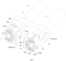
- Figure 1 shows an illustrative perspective view of a cooling device according to an exemplary embodiment of the present invention, wherein a charging terminal 4 and a charging cable 3 are shown;
- Figure 2 shows a vertical sectional view of a cooling device according to an exemplary embodiment of the present invention, wherein the charging terminal 4 and the charging cable 3 are shown;
- Figure 3 shows another vertical sectional view of a cooling device according to an exemplary embodiment of the present invention, in which charging terminal 4 and charging cable 3 are shown;
- Figure 4 shows a horizontal sectional view of a cooling device according to an exemplary embodiment of the present invention, wherein the charging terminal 4 and the charging cable 3 are shown.
- a cooling device mainly includes: multiple cooling modules 1 and a multi-channel pipe joint component 2.
- Each cooling module 1 has a containing chamber 101 for accommodating cooling liquid, and a first pipe joint 13 and a second pipe joint 11a communicated with the containing chamber 101.
- the multi-channel pipe joint component 2 includes multiple first mating pipe joints 21 interconnected with each other.
- the multiple first mating pipe joints 21 of the multi-channel pipe joint component 2 are respectively connected to the first pipe joints 13 of the multiple cooling modules 1, so that the containing chambers 101 of the multiple cooling modules 1 are connected to each other through the multi-channel pipe joint component 2.
- the second pipe joints 11a of multiple cooling modules 1 are used to connect with the cooling core pipes 31 of multiple charging cables 3 respectively, so that the cooling liquid can flow through the containing chambers 101 of multiple cooling modules 1 and the cooling core pipes 31 of multiple charging cables 3.
- the cooling module 1 includes a cooling box 10, and the inner cavity of the cooling box 10 constitutes the aforementioned containing chamber 101.
- the cooling box 10 includes a box body 11 with an opening and a cover plate 12 installed on the opening of the box body 11.
- the cover plate 12 is used to make thermal contact with the welding end 4a of the charging terminal 4, in order to transfer the heat of the charging terminal 4 to the cooling liquid inside the cooling box 10.
- the cover plate 12 is an insulation component that can conduct heat but not electricity
- the box body 11 is an insulation component that cannot conduct heat and electricity.
- the cover plate 12 is a ceramic component that can conduct heat but not electricity
- the box body 11 is an injection molded component that cannot conduct heat and electricity.
- the cooling module 1 further comprises a sealing ring 102, which is arranged around the opening of the box body 11 and compressed between the box body 11 and the cover plate 12 to achieve sealing between the box body 11 and the cover plate 12.
- a sealing ring installation groove is formed on at least one of the box body 11 and the cover plate 12, and the sealing ring 102 is positioned and installed in the sealing ring installation groove.
- the cooling module 1 further comprises a fixing device 14, which is installed on the box body 11 of the cooling box 10, for fixing the welding end 4a of the charging terminal 4 to the outer side of the cover plate 12 of the cooling box 10, so that the welding end 4a of the charging terminal 4 is reliably in thermal contact with the cover plate 12.
- a fixing device 14 which is installed on the box body 11 of the cooling box 10, for fixing the welding end 4a of the charging terminal 4 to the outer side of the cover plate 12 of the cooling box 10, so that the welding end 4a of the charging terminal 4 is reliably in thermal contact with the cover plate 12.
- the fixing device 14 includes a U-shaped component 140 and a bolt 143.
- the U-shaped component 140 is fixed to the box body 11, and a threaded connection hole 140a is formed through the U-shaped component 140.
- the bolt 143 is connected to the threaded connection hole 140a and pushes the welding end 4a of the charging terminal 4 against the cover plate 12 of the cooling box 10, so that there is a predetermined contact force between the welding end 4a of the charging terminal 4 and the cover plate 12 of the cooling box 10.
Landscapes
- Engineering & Computer Science (AREA)
- Microelectronics & Electronic Packaging (AREA)
- Power Engineering (AREA)
- Physics & Mathematics (AREA)
- Thermal Sciences (AREA)
- Transportation (AREA)
- Mechanical Engineering (AREA)
- Cooling Or The Like Of Electrical Apparatus (AREA)
- Connector Housings Or Holding Contact Members (AREA)
- Insulated Conductors (AREA)
Abstract
The present invention discloses a cooling device, a cooling system, and a charging device. The cooling device comprises of: multiple cooling modules (1), each cooling module (1) having a containing chamber (101) for containing cooling liquid, and a first pipe joint (13) and a second pipe joint (11a) communicated with the containing chamber (101); and a multi-channel pipe joint component (2) comprising multiple first mating pipe joints (21) interconnected with each other. The multiple first mating pipe joints (21) of the multi-channel pipe joint component (2) are respectively connected to the first pipe joints (13) of the multiple cooling modules (1), so that the containing chambers (101) of the multiple cooling modules (1) are connected to each other through the multi-channel pipe joint component (2), the second pipe joints (11a) of the multiple cooling modules (1) are used to connect with cooling core pipes (31) of multiple charging cables (3) respectively, so that the cooling liquid can flow through the containing chambers (101) of the multiple cooling modules (1) and the cooling core pipes (31) of the multiple charging cables (3). In the present invention, the cooling liquid can flow in and out through the cooling core pipe of the charging cable without the need for inlet and outlet pipes, simplifying the structure of the cooling device, reducing assembly steps, and lowering manufacturing costs.
Description
- This application claims the benefit of Chinese Patent Application No.
CN202311869732.X filed on December 29, 2023 - The present invention relates to a cooling device, a cooling system comprising the cooling device and a charging device comprising the cooling system.
- In the prior art, the charging seat usually includes a charging seat housing, a charging terminal set in the charging seat housing, and a charging cable electrically connected to the charging terminal. In order to improve the charging speed, it is necessary to increase the charging current. Currently, the charging current requirement is as high as 600A, and it may be further increased to 1000A in the future. When this high current flows through the charging cable and charging terminal, it will cause a sharp rise in the temperature inside the charging seat housing and the temperature of the charging cable. In order to prevent excessive temperature rise, in the prior art, the diameter of the charging cable is usually increased, but this will increase the volume and weight of the charging seat product, and lead to higher costs.
- In order to improve the cooling performance of the charging seat, a liquid cooled charging seat has recently been proposed. There is a containing chamber for accommodating cooling liquid in the housing of the liquid cooled charging seat, which has an inlet pipe joint for connecting with the cooling liquid inlet pipe and an outlet pipe joint for connecting with the cooling liquid outlet pipe. Therefore, in these technical solutions, separate cooling liquid inlet and outlet pipes need to be provided, and the cooling liquid inlet and outlet pipes also need to be connected to the inlet and outlet pipe joints of the containing chamber respectively. This will lead to an increase in the cost and complex assembly of the liquid cooled charging seat.
- The present invention has been made to overcome or alleviate at least one aspect of the above mentioned disadvantages.
- According to an aspect of the present invention, there is provided a cooling device. The cooling device comprises of: multiple cooling modules, each cooling module having a containing chamber for containing cooling liquid, and a first pipe joint and a second pipe joint communicated with the containing chamber; and a multi-channel pipe joint component comprising multiple first mating pipe joints interconnected with each other. The multiple first mating pipe joints of the multi-channel pipe joint component are respectively connected to the first pipe joints of the multiple cooling modules, so that the containing chambers of the multiple cooling modules are connected to each other through the multi-channel pipe joint component; the second pipe joints of the multiple cooling modules are used to connect with cooling core pipes of multiple charging cables respectively, so that the cooling liquid can flow through the containing chambers of the multiple cooling modules and the cooling core pipes of the multiple charging cables.
- According to an exemplary embodiment of the present invention, the cooling module comprises a cooling box for defining the containing chamber, the cooling box comprises a box body with an opening and a cover plate installed on the opening of the box body; the cover plate is used for thermal contact with a welding end of a charging terminal to transfer the heat of the charging terminal to the cooling liquid inside the cooling box.
- According to another exemplary embodiment of the present invention, the first pipe joint and the second pipe joint are integrally formed with the box body, so that the first pipe joint and the second pipe joint become part of the box body.
- According to another exemplary embodiment of the present invention, the cover plate is an insulation component that can conduct heat but not electricity, and the box body is an insulation component that cannot conduct heat and electricity.
- According to another exemplary embodiment of the present invention, the cover plate is a ceramic component that can conduct heat but not electricity, and the box body is an injection molded component that cannot conduct heat and electricity.
- According to another exemplary embodiment of the present invention, threaded holes are respectively formed in the box body and the cover plate, and the cooling module further comprises a threaded connection piece, which is connected to the threaded holes in the box body and the cover plate to fix the cover plate to the box body.
- According to another exemplary embodiment of the present invention, the cooling module further comprises a sealing ring which is set around the opening of the box body and compressed between the box body and the cover plate to achieve sealing between the box body and the cover plate.
- According to another exemplary embodiment of the present invention, a sealing ring installation groove is formed on at least one of the box body and the cover plate, and the sealing ring is positioned and installed in the sealing ring installation groove.
- According to another exemplary embodiment of the present invention, the cooling module further comprises a fixing device which is installed on the box body of the cooling box, used to fix the welding end of the charging terminal to the outside of the cover plate of the cooling box, so that the welding end of the charging terminal is in reliable thermal contact with the cover plate.
- According to another exemplary embodiment of the present invention, the fixing device comprises a U-shaped component and a bolt, wherein the U-shaped component is fixed to the box body, and a threaded connection hole is formed through the U-shaped component, the bolt is connected to the threaded connection hole and pushes the welding end of the charging terminal onto the cover plate of the cooling box, so that there is a predetermined contact force between the welding end of the charging terminal and the cover plate of the cooling box.
- According to another exemplary embodiment of the present invention, the U-shaped component comprises: a pair of side plates which are respectively fixed to both sides of the box body; and a top plate connected between the top of the pair of side plates. The top plate of the U-shaped component faces the conductor end of the charging cable welded to the welding end of the charging terminal, and the threaded connection hole is formed in the top plate of the U-shaped component, the bolt is pressed against the conductor end of the charging cable to push the welding end of the charging terminal onto the cover plate of the cooling box through the conductor end of the charging cable.
- According to another exemplary embodiment of the present invention, the pair of side plates of the U-shaped component are respectively formed with snap slots, and protrusions are respectively formed on both sides of the box body of the cooling box, the protrusions are engaged with the snap slots to fix the pair of side plates of the U-shaped component to both sides of the box body of the cooling box.
- According to another aspect of the present invention, there is provided a cooling system. The cooling system comprises of the above cooling device; and multiple charging cables, each charging cable comprising a cooling core pipe and a conductor. The ends of the cooling core pipes of the multiple charging cables are respectively connected to the second pipe joints of the multiple cooling modules of the cooling device, one of the cooling core pipes of the multiple charging cables is used as a cooling liquid inlet pipe, while the rest are used as cooling liquid outlet pipes.
- According to an exemplary embodiment of the present invention, the conductor of the charging cable is tubular, and the cooling core pipe is set in the conductor, the charging cable also includes an outer insulation layer wrapped around the outside of the conductor.
- According to another exemplary embodiment of the present invention, the conductor has a conductor end exposed from the outer insulation layer, which is used for welding to the welding end of the charging terminal; the end of the cooling core pipe is exposed from the outer insulation layer and connected to the second pipe joint of the cooling module.
- According to another aspect of the present invention, there is provided a charging device.
- The charging device comprises of: a housing; multiple charging terminals which are arranged in the housing; and the above cooling system installed in the housing. The welding ends of the multiple charging terminals are respectively welded to the conductor ends of the multiple charging cables of the cooling system and respectively fixed to the cover plates of the cooling boxes of the multiple cooling modules, so that the heat of the charging terminal can be transferred to the cooling liquid inside the cooling box through the cover plate of the cooling box.
- According to an exemplary embodiment of the present invention, the charging device is a charging seat suitable for mating with a charging gun, and the charging terminal is suitable for mating with a mating terminal in the charging gun.
- According to another exemplary embodiment of the present invention, the charging device is a charging gun suitable for mating with a charging seat, and the charging terminal is suitable for mating with a mating terminal in the charging seat.
- According to another exemplary embodiment of the present invention, the welding end of the charging terminal and the conductor end of the charging cable are flat and stacked and welded together.
- In the aforementioned exemplary embodiments according to the present invention, the containing chambers of multiple cooling modules are interconnected and adapted to be respectively connected to the cooling core pipes of multiple charging cables, so that cooling liquid can flow in and out through the cooling core pipes of the charging cables without providing separate cooling liquid inlet and outlet pipes, simplifying the structure of the cooling device, reducing assembly steps, and lowering manufacturing costs.
- The above and other features of the present invention will become more apparent by describing in detail exemplary embodiments thereof with reference to the accompanying drawings, in which:
-
Figure 1 shows an illustrative perspective view of a cooling device according to an exemplary embodiment of the present invention, wherein the charging terminal and charging cable are shown; -
Figure 2 shows a vertical sectional view of a cooling device according to an exemplary embodiment of the present invention, wherein the charging terminal and charging cable are shown; -
Figure 3 shows another vertical sectional view of a cooling device according to an exemplary embodiment of the present invention, wherein the charging terminal and charging cable are shown; and -
Figure 4 shows a horizontal sectional view of a cooling device according to an exemplary embodiment of the present invention, wherein the charging terminal and charging cable are shown. - Exemplary embodiments of the present disclosure will be described hereinafter in detail with reference to the attached drawings, wherein the like reference numerals refer to the like elements. The present disclosure may, however, be embodied in many different forms and should not be construed as being limited to the embodiment set forth herein; rather, these embodiments are provided so that the present disclosure will be thorough and complete, and will fully convey the concept of the disclosure to those skilled in the art.
- In the following detailed description, for purposes of explanation, numerous specific details are set forth in order to provide a thorough understanding of the disclosed embodiments. It will be apparent, however, that one or more embodiments may be practiced without these specific details. In other instances, well-known structures and devices are schematically shown in order to simplify the drawing.
- According to a general concept of the present invention, there is provided a cooling device. The cooling device comprises of multiple cooling modules, each cooling module having a containing chamber for containing cooling liquid, and a first pipe joint and a second pipe joint communicated with the containing chamber; and a multi-channel pipe joint component comprising multiple first mating pipe joints interconnected with each other. The multiple first mating pipe joints of the multi-channel pipe joint component are respectively connected to the first pipe joints of the multiple cooling modules, so that the containing chambers of the multiple cooling modules are connected to each other through the multi-channel pipe joint component; the second pipe joints of the multiple cooling modules are used to connect with cooling core pipes of multiple charging cables respectively, so that the cooling liquid can flow through the containing chambers of the multiple cooling modules and the cooling core pipes of the multiple charging cables.
- According to another general concept of the present invention, there is provided a cooling system. The cooling system comprises of the above cooling device; and multiple charging cables, each charging cable comprising a cooling core pipe and a conductor. The ends of the cooling core pipes of the multiple charging cables are respectively connected to the second pipe joints of the multiple cooling modules of the cooling device, one of the cooling core pipes of the multiple charging cables is used as a cooling liquid inlet pipe, while the rest are used as cooling liquid outlet pipes.
- According to another general concept of the present invention, there is provided a charging device. The charging device comprises of a housing; multiple charging terminals which are arranged in the housing; and the above cooling system installed in the housing. The welding ends of the multiple charging terminals are respectively welded to the conductor ends of the multiple charging cables of the cooling system and respectively fixed to the cover plates of the cooling boxes of the multiple cooling modules, so that the heat of the charging terminal can be transferred to the cooling liquid inside the cooling box through the cover plate of the cooling box.
-
Figure 1 shows an illustrative perspective view of a cooling device according to an exemplary embodiment of the present invention, wherein a chargingterminal 4 and a chargingcable 3 are shown;Figure 2 shows a vertical sectional view of a cooling device according to an exemplary embodiment of the present invention, wherein the chargingterminal 4 and the chargingcable 3 are shown;Figure 3 shows another vertical sectional view of a cooling device according to an exemplary embodiment of the present invention, in which chargingterminal 4 and chargingcable 3 are shown;Figure 4 shows a horizontal sectional view of a cooling device according to an exemplary embodiment of the present invention, wherein the chargingterminal 4 and the chargingcable 3 are shown. - As shown in
Figures 1 to 4 , in an exemplary embodiment of the present invention, a cooling device is disclosed. The cooling device mainly includes: multiple coolingmodules 1 and a multi-channel pipejoint component 2. Eachcooling module 1 has a containingchamber 101 for accommodating cooling liquid, and a first pipe joint 13 and a second pipe joint 11a communicated with the containingchamber 101. The multi-channel pipejoint component 2 includes multiple first mating pipe joints 21 interconnected with each other. The multiple first mating pipe joints 21 of the multi-channel pipejoint component 2 are respectively connected to the first pipe joints 13 of themultiple cooling modules 1, so that the containingchambers 101 of themultiple cooling modules 1 are connected to each other through the multi-channel pipejoint component 2. Thesecond pipe joints 11a ofmultiple cooling modules 1 are used to connect with thecooling core pipes 31 ofmultiple charging cables 3 respectively, so that the cooling liquid can flow through the containingchambers 101 ofmultiple cooling modules 1 and thecooling core pipes 31 ofmultiple charging cables 3. - As shown in
Figures 1 to 4 , in the illustrated embodiment, thecooling module 1 includes acooling box 10, and the inner cavity of thecooling box 10 constitutes the aforementioned containingchamber 101. Thecooling box 10 includes abox body 11 with an opening and acover plate 12 installed on the opening of thebox body 11. Thecover plate 12 is used to make thermal contact with thewelding end 4a of the chargingterminal 4, in order to transfer the heat of the chargingterminal 4 to the cooling liquid inside thecooling box 10. - As shown in
Figures 1 to 4 , in the illustrated embodiment, the first pipe joint 13 and the second pipe joint 11a are integrally formed with thebox body 11, so that the first pipe joint 13 and the second pipe joint 11a become part of thebox body 11. - As shown in
Figures 1 to 4 , in the illustrated embodiment, thecover plate 12 is an insulation component that can conduct heat but not electricity, and thebox body 11 is an insulation component that cannot conduct heat and electricity. In an exemplary embodiment of the present invention, thecover plate 12 is a ceramic component that can conduct heat but not electricity, and thebox body 11 is an injection molded component that cannot conduct heat and electricity. - As shown in
Figures 1 to 4 , in the illustrated embodiment, threaded holes are formed in thebox body 11 and thecover plate 12, respectively. Thecooling module 1 also includes a threadedconnection piece 103, which is connected to the threaded holes in thebox body 11 and thecover plate 12 to fix thecover plate 12 to thebox body 11. - As shown in
Figures 1 to 4 , in the illustrated embodiment, thecooling module 1 further comprises asealing ring 102, which is arranged around the opening of thebox body 11 and compressed between thebox body 11 and thecover plate 12 to achieve sealing between thebox body 11 and thecover plate 12. - As shown in
Figures 1 to 4 , in the illustrated embodiment, a sealing ring installation groove is formed on at least one of thebox body 11 and thecover plate 12, and thesealing ring 102 is positioned and installed in the sealing ring installation groove. - As shown in
Figures 1 to 4 , in the illustrated embodiment, thecooling module 1 further comprises a fixingdevice 14, which is installed on thebox body 11 of thecooling box 10, for fixing thewelding end 4a of the chargingterminal 4 to the outer side of thecover plate 12 of thecooling box 10, so that thewelding end 4a of the chargingterminal 4 is reliably in thermal contact with thecover plate 12. - As shown in
Figures 1 to 4 , in the illustrated embodiment, the fixingdevice 14 includes aU-shaped component 140 and abolt 143. TheU-shaped component 140 is fixed to thebox body 11, and a threadedconnection hole 140a is formed through theU-shaped component 140. Thebolt 143 is connected to the threadedconnection hole 140a and pushes thewelding end 4a of the chargingterminal 4 against thecover plate 12 of thecooling box 10, so that there is a predetermined contact force between the weldingend 4a of the chargingterminal 4 and thecover plate 12 of thecooling box 10. - As shown in
Figures 1 to 4 , in the illustrated embodiment, theU-shaped component 140 includes a pair ofside plates 142 and atop plate 141. The pair ofside plates 142 are respectively fixed to both sides of thebox body 11. Thetop plate 141 is connected between the top of the pair ofside plates 142. Thetop plate 141 of theU-shaped component 140 faces theconductor end 32a of the chargingcable 3 welded to thewelding end 4a of the chargingterminal 4, and a threadedconnection hole 140a is formed in thetop plate 141 of theU-shaped component 140. Thebolt 143 is pressed against theconductor end 32a of chargingcable 3 to push thewelding end 4a of chargingterminal 4 onto thecover plate 12 ofcooling box 10 through theconductor end 32a of chargingcable 3. - As shown in
Figures 1 to 4 , in the illustrated embodiment,snap slots 14a are respectively formed on the pair of side plates of theU-shaped component 140, andprotrusions 114a are formed on both sides of thebox body 11 of thecooling box 10. Theprotrusions 114a are engaged with thesnap slots 14a to fix the pair of side plates of theU-shaped component 140 to the two sides of thebox body 11 of thecooling box 10. - As shown in
Figures 1 to 4 , in another exemplary embodiment of the present invention, a cooling system is also disclosed. The cooling system mainly includes the aforementioned cooling device andmultiple charging cables 3. Each chargingcable 3 includes acooling core pipe 31 and aconductor 32. The ends 31a of thecooling core pipes 31 ofmultiple charging cables 3 are respectively connected to thesecond pipe joints 11a ofmultiple cooling modules 1 of the cooling device. One of thecooling core pipes 31 ofmultiple charging cables 3 is used as a cooling liquid inlet pipe, while the rest are used as cooling liquid outlet pipes. - As shown in
Figures 1 to 4 , in the illustrated embodiment, theconductor 32 of the chargingcable 3 is tubular, and thecooling core pipe 31 is set in theconductor 32. The chargingcable 3 also includes anouter insulation layer 33 wrapped around the outside of theconductor 32. - As shown in
Figures 1 to 4 , in the illustrated embodiment, theconductor 32 of the chargingcable 3 has aconductor end 32a exposed from theouter insulation layer 33, which is used for welding to thewelding end 4a of the chargingterminal 4. The end of thecooling core pipe 31 of the chargingcable 3 is exposed from theouter insulation layer 33 and connected to the second pipe joint 11a of thecooling module 1. - As shown in
Figures 1 to 4 , in another exemplary embodiment of the present invention, a charging device is also disclosed. The charging device mainly includes a housing (not shown),multiple charging terminals 4, and the aforementioned cooling system.Multiple charging terminals 4 and the cooling system are installed in the housing. The welding ends 4a ofmultiple charging terminals 4 are respectively welded to the conductor ends 12a ofmultiple charging cables 3 of the cooling system and respectively fixed to thecover plates 12 of the coolingboxes 10 ofmultiple cooling modules 1, so that the heat of the chargingterminal 4 can be transferred to the cooling liquid inside thecooling box 10 through thecover plate 12 of thecooling box 10. - As shown in
Figures 1 to 4 , in the illustrated embodiment, the charging device is a charging seat suitable for mating with a charging gun, and the chargingterminal 4 is suitable for mating with a mating terminal in the charging gun. However, the present invention is not limited to the illustrated embodiment. For example, in another exemplary embodiment of the present invention, the charging device is a charging gun suitable for mating with a charging seat, and the chargingterminal 4 is suitable for mating with a mating terminal in the charging seat. - As shown in
Figures 1 to 4 , in the illustrated embodiment, thewelding end 4a of the chargingterminal 4 and theconductor end 32a of the chargingcable 3 are flat and stacked and welded together. For example, they can be welded together using ultrasonic waves. - It should be appreciated for those skilled in this art that the above embodiments are intended to be illustrated, and not restrictive. For example, many modifications may be made to the above embodiments by those skilled in this art, and various features described in different embodiments may be freely combined with each other without conflicting in configuration or principle.
- Although several exemplary embodiments have been shown and described, it would be appreciated by those skilled in the art that various changes or modifications may be made in these embodiments without departing from the principles and spirit of the disclosure, the scope of which is defined in the claims and their equivalents.
- As used herein, an element recited in the singular and proceeded with the word "a" or "an" should be understood as not excluding plural of said elements or steps, unless such exclusion is explicitly stated. Furthermore, references to "one embodiment" of the present invention are not intended to be interpreted as excluding the existence of additional embodiments that also incorporate the recited features. Moreover, unless explicitly stated to the contrary, embodiments "comprising" or "having" an element or a plurality of elements having a particular property may include additional such elements not having that property.
Claims (15)
- A cooling device, comprising:multiple cooling modules (1), each cooling module (1) having a containing chamber (101) for containing cooling liquid, and a first pipe joint (13) and a second pipe joint (11a) communicated with the containing chamber (101); anda multi-channel pipe joint component (2) comprising multiple first mating pipe joints (21) interconnected with each other,wherein the multiple first mating pipe joints (21) of the multi-channel pipe joint component (2) are respectively connected to the first pipe joints (13) of the multiple cooling modules (1), so that the containing chambers (101) of the multiple cooling modules (1) are connected to each other through the multi-channel pipe joint component (2),wherein the second pipe joints (11a) of the multiple cooling modules (1) are used to connect with cooling core pipes (31) of multiple charging cables (3) respectively, so that the cooling liquid can flow through the containing chambers (101) of the multiple cooling modules (1) and the cooling core pipes (31) of the multiple charging cables (3).
- The cooling device according to claim 1,wherein the cooling module (1) comprises a cooling box (10) for defining the containing chamber (101), the cooling box (10) comprises a box body (11) with an opening and a cover plate (12) installed on the opening of the box body (11);wherein the cover plate (12) is used for thermal contact with a welding end (4a) of a charging terminal (4) to transfer the heat of the charging terminal (4) to the cooling liquid inside the cooling box (10).
- The cooling device according to claim 2,
wherein the first pipe joint (13) and the second pipe joint (11a) are integrally formed with the box body (11), so that the first pipe joint (13) and the second pipe joint (11a) become part of the box body (11). - The cooling device according to claim 3,
wherein the cover plate (12) is an insulation component that can conduct heat but not electricity, and the box body (11) is an insulation component that cannot conduct heat and electricity. - The cooling device according to claim 2,
wherein threaded holes are respectively formed in the box body (11) and the cover plate (12), and the cooling module (1) further comprises a threaded connection piece (103), which is connected to the threaded holes in the box body (11) and the cover plate (12) to fix the cover plate (12) to the box body (11). - The cooling device according to claim 2,wherein the cooling module (1) further comprises:
a sealing ring (102) which is set around the opening of the box body (11) and compressed between the box body (11) and the cover plate (12) to achieve sealing between the box body (11) and the cover plate (12),wherein a sealing ring installation groove is formed on at least one of the box body (11) and the cover plate (12), and the sealing ring (102) is positioned and installed in the sealing ring installation groove. - The cooling device according to claim 2,
wherein the cooling module (1) further comprises:
a fixing device (14) which is installed on the box body (11) of the cooling box (10), used to fix the welding end (4a) of the charging terminal (4) to the outside of the cover plate (12) of the cooling box (10), so that the welding end (4a) of the charging terminal (4) is in reliable thermal contact with the cover plate (12). - The cooling device according to claim 7,
wherein the fixing device (14) comprises a U-shaped component (140) and a bolt (143), wherein the U-shaped component (140) is fixed to the box body (11), and a threaded connection hole (140a) is formed through the U-shaped component (140), the bolt (143) is connected to the threaded connection hole (140a) and pushes the welding end (4a) of the charging terminal (4) onto the cover plate (12) of the cooling box (10), so that there is a predetermined contact force between the welding end (4a) of the charging terminal (4) and the cover plate (12) of the cooling box (10). - The cooling device according to claim 8,wherein the U-shaped component (140) comprises:a pair of side plates (142) which are respectively fixed to both sides of the box body (11); anda top plate (141) connected between the top of the pair of side plates (142),wherein the top plate (141) of the U-shaped component (140) faces the conductor end (32a) of the charging cable (3) welded to the welding end (4a) of the charging terminal (4), and the threaded connection hole (140a) is formed in the top plate (141) of the U-shaped component (140),wherein the bolt (143) is pressed against the conductor end (32a) of the charging cable (3) to push the welding end (4a) of the charging terminal (4) onto the cover plate (12) of the cooling box (10) through the conductor end (32a) of the charging cable (3).
- The cooling device according to claim 9,
wherein the pair of side plates (142) of the U-shaped component (140) are respectively formed with snap slots (14a), and protrusions (114a) are respectively formed on both sides of the box body (11) of the cooling box (10), the protrusions (114a) are engaged with the snap slots (14a) to fix the pair of side plates (142) of the U-shaped component (140) to both sides of the box body (11) of the cooling box (10). - A cooling system, comprising:the cooling device as claimed in any one of claims 1-10; andmultiple charging cables (3), each charging cable (3) comprising a cooling core pipe (31) and a conductor (32),wherein the ends (31a) of the cooling core pipes (31) of the multiple charging cables (3) are respectively connected to the second pipe joints (11a) of the multiple cooling modules (1) of the cooling device,wherein one of the cooling core pipes (31) of the multiple charging cables (3) is used as a cooling liquid inlet pipe, while the rest are used as cooling liquid outlet pipes.
- The cooling system according to claim 11,
wherein the conductor (32) of the charging cable (3) is tubular, and the cooling core pipe (31) is set in the conductor (32), the charging cable (3) also includes an outer insulation layer (33) wrapped around the outside of the conductor (32). - The cooling system according to claim 12,wherein the conductor (32) has a conductor end (32a) exposed from the outer insulation layer (33), which is used for welding to the welding end (4a) of the charging terminal (4);wherein the end (31a) of the cooling core pipe (31) is exposed from the outer insulation layer (33) and connected to the second pipe joint (11a) of the cooling module (1).
- A charging device, comprising:a housing;multiple charging terminals (4) which are arranged in the housing; andthe cooling system according to any one of claims 11-13, installed in the housing,wherein the welding ends (4a) of the multiple charging terminals (4) are respectively welded to the conductor ends (32a) of the multiple charging cables (3) of the cooling system and respectively fixed to the cover plates (12) of the cooling boxes (10) of the multiple cooling modules (1), so that the heat of the charging terminal (4) can be transferred to the cooling liquid inside the cooling box (10) through the cover plate (12) of the cooling box (10).
- The charging device according to claim 14,wherein the charging device is a charging seat suitable for mating with a charging gun, and the charging terminal (4) is suitable for mating with a mating terminal in the charging gun; orwherein the charging device is a charging gun suitable for mating with a charging seat, and the charging terminal (4) is suitable for mating with a mating terminal in the charging seat.
Applications Claiming Priority (1)
| Application Number | Priority Date | Filing Date | Title |
|---|---|---|---|
| CN202311869732.XA CN120239227A (en) | 2023-12-29 | 2023-12-29 | Cooling devices, cooling systems and charging devices |
Publications (1)
| Publication Number | Publication Date |
|---|---|
| EP4582301A1 true EP4582301A1 (en) | 2025-07-09 |
Family
ID=93925971
Family Applications (1)
| Application Number | Title | Priority Date | Filing Date |
|---|---|---|---|
| EP24222412.9A Pending EP4582301A1 (en) | 2023-12-29 | 2024-12-20 | Cooling device, cooling system and charging device |
Country Status (4)
| Country | Link |
|---|---|
| EP (1) | EP4582301A1 (en) |
| JP (1) | JP2025105549A (en) |
| KR (1) | KR20250105224A (en) |
| CN (1) | CN120239227A (en) |
Citations (4)
| Publication number | Priority date | Publication date | Assignee | Title |
|---|---|---|---|---|
| DE102016204895B4 (en) * | 2016-03-23 | 2020-11-12 | Phoenix Contact E-Mobility Gmbh | Charging connector with a power contact system and charging station for delivering electrical energy to a receiver of electrical energy |
| US20220337006A1 (en) * | 2019-07-25 | 2022-10-20 | Abb Schweiz Ag | Vehicle Charging System for Charging an Electrical Vehicle |
| US20230163520A1 (en) * | 2021-11-19 | 2023-05-25 | Luxshare Precision Industry (Jiangsu)Co.,Ltd. | Liquid cooling system for a charging gun and charging gun |
| CN220020708U (en) * | 2023-06-05 | 2023-11-14 | 泰科电子(上海)有限公司 | Charging stand |
-
2023
- 2023-12-29 CN CN202311869732.XA patent/CN120239227A/en active Pending
-
2024
- 2024-12-20 EP EP24222412.9A patent/EP4582301A1/en active Pending
- 2024-12-25 JP JP2024228093A patent/JP2025105549A/en active Pending
- 2024-12-26 KR KR1020240196721A patent/KR20250105224A/en active Pending
Patent Citations (4)
| Publication number | Priority date | Publication date | Assignee | Title |
|---|---|---|---|---|
| DE102016204895B4 (en) * | 2016-03-23 | 2020-11-12 | Phoenix Contact E-Mobility Gmbh | Charging connector with a power contact system and charging station for delivering electrical energy to a receiver of electrical energy |
| US20220337006A1 (en) * | 2019-07-25 | 2022-10-20 | Abb Schweiz Ag | Vehicle Charging System for Charging an Electrical Vehicle |
| US20230163520A1 (en) * | 2021-11-19 | 2023-05-25 | Luxshare Precision Industry (Jiangsu)Co.,Ltd. | Liquid cooling system for a charging gun and charging gun |
| CN220020708U (en) * | 2023-06-05 | 2023-11-14 | 泰科电子(上海)有限公司 | Charging stand |
Also Published As
| Publication number | Publication date |
|---|---|
| KR20250105224A (en) | 2025-07-08 |
| CN120239227A (en) | 2025-07-01 |
| JP2025105549A (en) | 2025-07-10 |
Similar Documents
| Publication | Publication Date | Title |
|---|---|---|
| JP7359904B2 (en) | Refrigerant distributor for battery module housing and its manufacturing method | |
| US11852271B2 (en) | Modular heater systems | |
| EP4718580A1 (en) | Battery module and battery pack | |
| EP4582301A1 (en) | Cooling device, cooling system and charging device | |
| EP4578718A1 (en) | Cooling device, cooling system and charging device | |
| EP4578714A1 (en) | Cooling module, electrical connection module and charging device | |
| CN221575931U (en) | Cooling devices, cooling systems and charging devices | |
| CN118046773A (en) | Charging socket and cooling assembly | |
| EP4559731A1 (en) | Rear housing for charging seat and charging seat | |
| EP4574543A1 (en) | Charging terminal cooling box and charging seat | |
| EP4578713A1 (en) | Charging terminal fixing component, top cover assembly, charging terminal cooling box and charging seat | |
| CN221653070U (en) | Cooling devices, cooling systems and charging devices | |
| KR20250105223A (en) | Cooling module, electrical connection module and charging device | |
| CN221689124U (en) | Cooling module, electrical connection module and charging device | |
| EP4675873A2 (en) | Power transmission member, power transmission assembly, electrical connection assembly, and electrical connection device | |
| EP4675650A2 (en) | Power transmission member, power transmission assembly, electrical connection assembly, and electrical connection device | |
| CN221634285U (en) | Cooling module, electric connection module and charging device | |
| US20260106266A1 (en) | Battery pack | |
| CN224191785U (en) | Motor and engineering machinery | |
| CN115885411A (en) | Cooling jacket assembly and method of making same |
Legal Events
| Date | Code | Title | Description |
|---|---|---|---|
| PUAI | Public reference made under article 153(3) epc to a published international application that has entered the european phase |
Free format text: ORIGINAL CODE: 0009012 |
|
| STAA | Information on the status of an ep patent application or granted ep patent |
Free format text: STATUS: THE APPLICATION HAS BEEN PUBLISHED |
|
| AK | Designated contracting states |
Kind code of ref document: A1 Designated state(s): AL AT BE BG CH CY CZ DE DK EE ES FI FR GB GR HR HU IE IS IT LI LT LU LV MC ME MK MT NL NO PL PT RO RS SE SI SK SM TR |
|
| STAA | Information on the status of an ep patent application or granted ep patent |
Free format text: STATUS: REQUEST FOR EXAMINATION WAS MADE |
|
| 17P | Request for examination filed |
Effective date: 20251219 |