EP4582278A1 - Automobile and dual-electric-motor electric drive assembly thereof - Google Patents
Automobile and dual-electric-motor electric drive assembly thereof Download PDFInfo
- Publication number
- EP4582278A1 EP4582278A1 EP23918204.1A EP23918204A EP4582278A1 EP 4582278 A1 EP4582278 A1 EP 4582278A1 EP 23918204 A EP23918204 A EP 23918204A EP 4582278 A1 EP4582278 A1 EP 4582278A1
- Authority
- EP
- European Patent Office
- Prior art keywords
- gear
- shaft
- parallel
- spoke
- motor
- Prior art date
- Legal status (The legal status is an assumption and is not a legal conclusion. Google has not performed a legal analysis and makes no representation as to the accuracy of the status listed.)
- Pending
Links
Images


Classifications
-
- B—PERFORMING OPERATIONS; TRANSPORTING
- B60—VEHICLES IN GENERAL
- B60K—ARRANGEMENT OR MOUNTING OF PROPULSION UNITS OR OF TRANSMISSIONS IN VEHICLES; ARRANGEMENT OR MOUNTING OF PLURAL DIVERSE PRIME-MOVERS IN VEHICLES; AUXILIARY DRIVES FOR VEHICLES; INSTRUMENTATION OR DASHBOARDS FOR VEHICLES; ARRANGEMENTS IN CONNECTION WITH COOLING, AIR INTAKE, GAS EXHAUST OR FUEL SUPPLY OF PROPULSION UNITS IN VEHICLES
- B60K1/00—Arrangement or mounting of electrical propulsion units
- B60K1/02—Arrangement or mounting of electrical propulsion units comprising more than one electric motor
-
- B—PERFORMING OPERATIONS; TRANSPORTING
- B60—VEHICLES IN GENERAL
- B60B—VEHICLE WHEELS; CASTORS; AXLES FOR WHEELS OR CASTORS; INCREASING WHEEL ADHESION
- B60B35/00—Axle units; Parts thereof ; Arrangements for lubrication of axles
- B60B35/12—Torque-transmitting axles
- B60B35/14—Torque-transmitting axles composite or split, e.g. half- axles; Couplings between axle parts or sections
-
- B—PERFORMING OPERATIONS; TRANSPORTING
- B60—VEHICLES IN GENERAL
- B60K—ARRANGEMENT OR MOUNTING OF PROPULSION UNITS OR OF TRANSMISSIONS IN VEHICLES; ARRANGEMENT OR MOUNTING OF PLURAL DIVERSE PRIME-MOVERS IN VEHICLES; AUXILIARY DRIVES FOR VEHICLES; INSTRUMENTATION OR DASHBOARDS FOR VEHICLES; ARRANGEMENTS IN CONNECTION WITH COOLING, AIR INTAKE, GAS EXHAUST OR FUEL SUPPLY OF PROPULSION UNITS IN VEHICLES
- B60K17/00—Arrangement or mounting of transmissions in vehicles
- B60K17/04—Arrangement or mounting of transmissions in vehicles characterised by arrangement, location or kind of gearing
- B60K17/043—Transmission unit disposed in on near the vehicle wheel, or between the differential gear unit and the wheel
-
- B—PERFORMING OPERATIONS; TRANSPORTING
- B60—VEHICLES IN GENERAL
- B60K—ARRANGEMENT OR MOUNTING OF PROPULSION UNITS OR OF TRANSMISSIONS IN VEHICLES; ARRANGEMENT OR MOUNTING OF PLURAL DIVERSE PRIME-MOVERS IN VEHICLES; AUXILIARY DRIVES FOR VEHICLES; INSTRUMENTATION OR DASHBOARDS FOR VEHICLES; ARRANGEMENTS IN CONNECTION WITH COOLING, AIR INTAKE, GAS EXHAUST OR FUEL SUPPLY OF PROPULSION UNITS IN VEHICLES
- B60K17/00—Arrangement or mounting of transmissions in vehicles
- B60K17/04—Arrangement or mounting of transmissions in vehicles characterised by arrangement, location or kind of gearing
- B60K17/06—Arrangement or mounting of transmissions in vehicles characterised by arrangement, location or kind of gearing of change-speed gearing
- B60K17/08—Arrangement or mounting of transmissions in vehicles characterised by arrangement, location or kind of gearing of change-speed gearing of mechanical type
-
- B—PERFORMING OPERATIONS; TRANSPORTING
- B60—VEHICLES IN GENERAL
- B60K—ARRANGEMENT OR MOUNTING OF PROPULSION UNITS OR OF TRANSMISSIONS IN VEHICLES; ARRANGEMENT OR MOUNTING OF PLURAL DIVERSE PRIME-MOVERS IN VEHICLES; AUXILIARY DRIVES FOR VEHICLES; INSTRUMENTATION OR DASHBOARDS FOR VEHICLES; ARRANGEMENTS IN CONNECTION WITH COOLING, AIR INTAKE, GAS EXHAUST OR FUEL SUPPLY OF PROPULSION UNITS IN VEHICLES
- B60K7/00—Disposition of motor in, or adjacent to, traction wheel
- B60K7/0007—Disposition of motor in, or adjacent to, traction wheel the motor being electric
-
- F—MECHANICAL ENGINEERING; LIGHTING; HEATING; WEAPONS; BLASTING
- F16—ENGINEERING ELEMENTS AND UNITS; GENERAL MEASURES FOR PRODUCING AND MAINTAINING EFFECTIVE FUNCTIONING OF MACHINES OR INSTALLATIONS; THERMAL INSULATION IN GENERAL
- F16H—GEARING
- F16H1/00—Toothed gearings for conveying rotary motion
- F16H1/02—Toothed gearings for conveying rotary motion without gears having orbital motion
- F16H1/20—Toothed gearings for conveying rotary motion without gears having orbital motion involving more than two intermeshing members
-
- F—MECHANICAL ENGINEERING; LIGHTING; HEATING; WEAPONS; BLASTING
- F16—ENGINEERING ELEMENTS AND UNITS; GENERAL MEASURES FOR PRODUCING AND MAINTAINING EFFECTIVE FUNCTIONING OF MACHINES OR INSTALLATIONS; THERMAL INSULATION IN GENERAL
- F16H—GEARING
- F16H57/00—General details of gearing
- F16H57/0006—Vibration-damping or noise reducing means specially adapted for gearings
-
- B—PERFORMING OPERATIONS; TRANSPORTING
- B60—VEHICLES IN GENERAL
- B60B—VEHICLE WHEELS; CASTORS; AXLES FOR WHEELS OR CASTORS; INCREASING WHEEL ADHESION
- B60B35/00—Axle units; Parts thereof ; Arrangements for lubrication of axles
- B60B35/12—Torque-transmitting axles
-
- B—PERFORMING OPERATIONS; TRANSPORTING
- B60—VEHICLES IN GENERAL
- B60K—ARRANGEMENT OR MOUNTING OF PROPULSION UNITS OR OF TRANSMISSIONS IN VEHICLES; ARRANGEMENT OR MOUNTING OF PLURAL DIVERSE PRIME-MOVERS IN VEHICLES; AUXILIARY DRIVES FOR VEHICLES; INSTRUMENTATION OR DASHBOARDS FOR VEHICLES; ARRANGEMENTS IN CONNECTION WITH COOLING, AIR INTAKE, GAS EXHAUST OR FUEL SUPPLY OF PROPULSION UNITS IN VEHICLES
- B60K7/00—Disposition of motor in, or adjacent to, traction wheel
- B60K2007/0061—Disposition of motor in, or adjacent to, traction wheel the motor axle being parallel to the wheel axle
-
- F—MECHANICAL ENGINEERING; LIGHTING; HEATING; WEAPONS; BLASTING
- F16—ENGINEERING ELEMENTS AND UNITS; GENERAL MEASURES FOR PRODUCING AND MAINTAINING EFFECTIVE FUNCTIONING OF MACHINES OR INSTALLATIONS; THERMAL INSULATION IN GENERAL
- F16H—GEARING
- F16H55/00—Elements with teeth or friction surfaces for conveying motion; Worms, pulleys or sheaves for gearing mechanisms
- F16H55/02—Toothed members; Worms
- F16H55/17—Toothed wheels
Definitions
- the present disclosure relates to an electric vehicle technology, and in particular, to a vehicle and a dual-electric motor electric drive assembly thereof.
- the dual-electric motor electric drive assembly has overlapping orders and louder noise, resulting in a reduction in Noise, Vibration, Harshness (NVH) performance of the vehicle.
- NSH Noise, Vibration, Harshness
- the present disclosure provides a dual-electric motor electric drive assembly.
- the dual-electric motor electric drive assembly include a first drive mechanism and a second drive mechanism that are located at one drive axle.
- the first drive mechanism includes a first motor, a first parallel shaft gear mechanism, and a first half shaft that are connected sequentially.
- the second drive mechanism includes a second motor, a second parallel shaft gear mechanism, and a second half shaft that are connected sequentially.
- a structure of the first drive mechanism is different from a structure of the second drive mechanism to prevent an overlapping of a resonance frequency of the first drive mechanism and a resonance frequency of the second drive mechanism.
- a gear of the first parallel shaft gear mechanism is different from a gear of the second parallel shaft gear mechanism in shape.
- a spoke of the gear of the first parallel shaft gear mechanism is different from a spoke of the gear of the second parallel shaft gear mechanism in shape and/or thickness.
- a rotary shaft of the first parallel shaft gear mechanism is different from a rotary shaft of the second parallel shaft gear mechanism in length and/or shape.
- the first half shaft is different from the second half shaft in length and/or shape.
- the first motor includes a first main shaft connected to the first parallel shaft gear mechanism; and the second motor includes a second main shaft connected to the second parallel shaft gear mechanism.
- the first main shaft is different from the second main shaft in length and/or shape.
- a bearing of the first parallel shaft gear mechanism is different from a bearing of the second parallel shaft gear mechanism in type and/or size.
- the dual-electric motor electric drive assembly further includes a housing configured to accommodate the first motor, the first parallel shaft gear mechanism, the first half shaft, the second motor, the second parallel shaft gear mechanism, and the second half shaft; and a shape of the housing located at a side of the housing close to the first driving mechanism is different from a shape of the housing located at a side of the housing close to the second driving mechanism.
- the first parallel shaft gear mechanism includes: a first gear sleeved over and connected to the first main shaft; a first rotary shaft disposed at a side of the first main shaft and parallel to the first main shaft.
- the first rotary shaft is rotatable around its own axis; a second gear sleeved over the first rotary shaft, connected to the first rotary shaft, and engaged with the first gear; a third gear sleeved over and connected to the first rotary shaft; and a fourth gear sleeved over the first half shaft, connected to the first half shaft, and engaged with the third gear.
- the second parallel shaft gear mechanism includes: a fifth gear sleeved over and connected to the second main shaft; a second rotary shaft disposed at a side of the second main shaft and parallel to the second main shaft.
- the second rotary shaft is around its own axis; a sixth gear sleeved over the second rotary shaft, connected to the second rotary shaft, and engaged with the fifth gear; a seventh gear sleeved over and connected to the second rotary shaft; and an eighth gear sleeved over the second half shaft, connected to the second half shaft, and engaged with the seventh gear.
- a spoke of the first gear is different from a spoke of the fifth gear in shape and/or wall thickness.
- a spoke of the second gear is different from a spoke of the sixth gear in shape and/or wall thickness.
- a spoke of the third gear is different from a spoke of the seventh gear in shape and/or wall thickness, and a spoke of the fourth gear is different from a spoke of the eighth gear in shape and/or wall thickness.
- a length of the first rotary shaft is different from a length of the second rotary shaft.
- the present disclosure also provides a vehicle.
- the vehicle includes the dual-electric motor electric drive assembly as described above.
- the structure of the first drive mechanism is different from the structure of the second drive mechanism, orders of the first drive mechanism and the second drive mechanism are separated, thereby avoiding an order overlap of the first drive mechanism and the second drive mechanism.
- order noise when the first drive mechanism and the second drive mechanism operate simultaneously can be significantly reduced, improving NVH performance of the vehicle and obtaining a better driving experience.
- the first motor and the second motor may each be a motor with low power. When the first motor and the second motor operate simultaneously, the dual-electric motor electric drive assembly may output larger power to satisfy high-power output requirements of the vehicle.
- first motor and the second motor may be controlled separately, power output at a side or two sides of the vehicle may be changed as power requirements, to realize functions of vehicle differential speed, differential lock, vector control, and the like, making the control more accurate.
- first motor and the second motor may be controlled separately, power output at a side or two sides of the vehicle may be changed as power requirements, to realize functions of vehicle differential speed, differential lock, vector control, and the like, making the control more accurate.
- rotational speeds and torques of the first motor and the second motor a differential speed and torque distribution between vehicle wheels may be realized, realizing straight traveling of the vehicle.
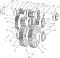
- FIG. 1 illustrates a structure of a dual-electric motor electric drive assembly 100 according to an embodiment.
- the dual-electric motor electric drive assembly 100 is mounted on a vehicle and provides the vehicle with driving power.
- the vehicle may be a pure electric vehicle.
- the dual-electric motor electric drive assembly 100 includes a first drive mechanism 1 and a second drive mechanism 2.
- the first drive mechanism 1 and the second drive mechanism 2 may be disposed at one drive axle.
- the first drive mechanism 1 includes a first motor 11, a first parallel shaft gear mechanism 12, and a first half shaft 13.
- the first parallel shaft gear mechanism 12 is disposed between the first half shaft 13 and the first motor 11.
- a main shaft of the first motor 11 is connected to the first parallel shaft gear mechanism 12, and the first parallel shaft gear mechanism 12 is connected to the first half shaft 13.
- the first parallel shaft gear mechanism 12 may be a speed reducer. After reducing a speed of a torque outputted by the first motor 11 and increasing the outputted torque, the first parallel shaft gear mechanism 12 may transmit the torque to the first half shaft 13 to drive the first half shaft 13 to rotate.
- the second drive mechanism 2 includes a second motor 21, a second parallel shaft gear mechanism 22, and a second half shaft 23.
- the second parallel shaft gear mechanism 22 is disposed between the second half shaft 23 and the second motor 21.
- a main shaft of the second motor 21 is connected to the second parallel shaft gear mechanism 22, and the second parallel shaft gear mechanism 22 is connected to the second half shaft 23.
- the second parallel shaft gear mechanism 22 may be a speed reducer. After reducing a speed of a torque outputted by the second motor 21 and increasing the outputted torque, the second parallel shaft gear mechanism 22 may transmit the torque to the second half shaft 23 to drive the second half shaft 23 to rotate.
- the first parallel shaft gear mechanism 12 and the second parallel shaft gear mechanism 22 are disposed close to each other.
- the first motor 11 and the second motor 12 are respectively disposed at one side of the first parallel shaft gear mechanism 12 and the second parallel shaft gear mechanism 22.
- the first motor 11 and the second motor 21 are arranged coaxially.
- the first half shaft 13 is disposed at a side of the first parallel shaft gear mechanism 12 facing away from the first motor 11.
- the second half shaft 23 is disposed at a side of the second parallel shaft gear mechanism 22 facing away from the second motor 21.
- the first half shaft 13 and the second half shaft 23 are arranged coaxially.
- a structure of the first drive mechanism 1 is different from a structure of the second drive mechanism 2 to prevent an overlapping of a resonance frequency of the first drive mechanism 1 and a resonance frequency of the second drive mechanism 2.
- the first motor 11 of the first drive mechanism 1 is different from the second motor 21 of the second drive mechanism 2 in structure.
- the first parallel shaft gear mechanism 12 of the first drive mechanism 1 is different from the second parallel shaft gear mechanism 22 of the second drive mechanism 2 in structure.
- the first half shaft 13 of the first drive mechanism 1 and the second half shaft 23 of the second drive mechanism 2 has a same structure.
- first motor 11 and the second motor 21 may be controlled separately, power output at a side or two sides of the vehicle may be changed as power requirements, to realize functions of vehicle differential speed, differential lock, vector control, and the like, making the control more accurate.
- first motor 11 and the second motor 21 may be controlled separately, power output at a side or two sides of the vehicle may be changed as power requirements, to realize functions of vehicle differential speed, differential lock, vector control, and the like, making the control more accurate.
- a differential speed and torque distribution between vehicle wheels may be realized, realizing straight traveling of the vehicle.
- the first motor 11 includes a first body 111 and a first main shaft 112.
- the first body 111 is constructed as a cylindrical shape.
- the first main shaft 112 extends out from an end of the first body 111.
- the first main shaft 112 and the first body 111 are arranged coaxially.
- the second motor 21 includes a second body 211 and a second main shaft 212.
- the second body 211 is constructed as a cylindrical shape.
- the first body 111 and the second body 211 are arranged coaxially.
- the first main shaft 112 and the second main shaft 212 extend opposite to each other from an end where the first body 111 and the second body 211 are close to each other, respectively.
- the first main shaft 112 is coaxial with the second main shaft 212.
- the first parallel shaft gear mechanism 12 includes a first gear 121, a first rotary shaft 125, a second gear 122, a third gear 123, and a fourth gear 124.
- the first gear 121, the second gear 122, the third gear 123, and the fourth gear 124 are each cylindrical gears, and may be each helical gears.
- the first gear 121 is sleeved over and fixedly connected to the first main shaft 112. There may be a key connection between the first gear 121 and the first main shaft 112, such as a spline connection or a flat key connection.
- the first rotary shaft 125 is disposed at a side of the first main shaft 112 of the first motor 11 and parallel to the first main shaft 112.
- the first rotary shaft is around its own axis.
- the second gear 122 is sleeved over the first rotary shaft 125.
- the second gear 122 and the first rotary shaft 125 are connected together.
- the second gear 122 is engaged with the first gear 121.
- An outer diameter of the second gear 122 may be greater than an outer diameter of the first gear 121.
- the third gear 123 is sleeved over and fixedly connected to the first rotary shaft 125.
- the third gear 123 may be in a key connection, in a flat key connection, or in a spline connection with the first rotary shaft 125.
- An outer diameter of the third gear 123 may be smaller than the outer diameter of the second gear 122.
- the fourth gear 124 is sleeved over and connected to the first half shaft 13. There may be a key connection between the fourth gear 124 and the first half shaft 13, such as a spline connection or a flat key connection.
- the fourth gear 124 is engaged with the third gear 123.
- An outer diameter of the fourth gear 124 may be greater than the outer diameter of the third gear 123.
- the first main shaft 112 of the first motor 11 drives the first gear 121 to rotate.
- the first gear 121 drives the second gear 122 to rotate.
- the second gear 122 drives the first rotary shaft 125 to rotate.
- the first rotary shaft 125 drives the third gear 123 to rotate.
- the third gear 123 drives the fourth gear 124 to rotate.
- the fourth gear 124 drives the first half shaft 13 to rotate.
- the second parallel shaft gear mechanism 22 includes a fifth gear 221, a second rotary shaft 225, a sixth gear 222, a seventh gear 223, and an eighth gear 224.
- the fifth gear 221, the sixth gear 222, the seventh gear 223, and the eighth gear 224 are each cylindrical gears, and may be each helical gears.
- the fifth gear 221 is sleeved over and fixedly connected to the second main shaft 212. There may be a key connection between the fifth gear 221 and the second main shaft 212, such as a spline connection or a flat key connection.
- the second rotary shaft 225 is disposed at a side of the second main shaft 212 of the second motor 21 and parallel to the second main shaft 212. The second rotary shaft is around its own axis.
- the sixth gear 222 is sleeved over the second rotary shaft 225.
- the sixth gear 222 and the second rotary shaft 225 are connected together.
- the sixth gear 222 is engaged with the fifth gear 221.
- An outer diameter of the sixth gear 222 may be greater than an outer diameter of the fifth gear 221.
- the seventh gear 223 is sleeved over and fixedly connected to the second rotary shaft 225.
- the seventh gear 223 may be in a key connection, in a flat key connection, or in a spline connection with the second rotary shaft 225.
- An outer diameter of the seventh gear 223 may be smaller than the outer diameter of the sixth gear 222.
- the eighth gear 224 is sleeved over and connected to the second half shaft 23. There is a key connection between the eighth gear 224 and the second half shaft 23, such as a spline connection or a flat key connection.
- the eighth gear 224 is engaged with the seventh gear 223.
- An outer diameter of the eighth gear 224 is greater than the outer diameter of the seventh gear 223.
- the second main shaft 212 of the second motor 21 drives the fifth gear 221 to rotate.
- the fifth gear 221 drives the sixth gear 222 to rotate.
- the sixth gear 222 drives the second rotary shaft 225 to rotate.
- the second rotary shaft 225 drives the seventh gear 223 to rotate.
- the seventh gear 223 drives the eighth gear 224 to rotate.
- the eighth gear 224 drives the second half shaft 23 to rotate.
- each of the gears includes a hub 41, a spoke 42, and a rim 43.
- the hub 41 is located in a middle part of the gear and constructed as a cylindrical or annular shape.
- the hub 41 is sleeved over the rotary shaft and connected to the rotary shaft.
- the rim 43 is annular and located at an outermost side of the gear, and tooth is provided on the rim 43.
- the spoke 42 is located between the rim 43 and the hub 41 and connects the rim 43 and the hub 41.
- the first gear 121 is arranged corresponding to the fifth gear 221, and the first gear 121 and the fifth gear 221 may have a same outer diameter.
- a spoke of the first gear 121 is different from a spoke of the fifth gear 221 in structure.
- One of the spoke of the first gear 121 and the spoke of the fifth gear 221 is constructed as a plate-shaped structure having a weight reduction hole, and the other one of the spoke of the first gear 121 and the spoke of the fifth gear 221 is constructed as a spoke-shaped structure.
- each of the spoke of the first gear 121 and the spoke of the fifth gear 221 is constructed to have a plate-shaped structure with a weight reduction hole, and the spoke of the first gear 121 is different from the spoke of the fifth gear 221 in thickness.
- the second gear 122 is arranged corresponding to the sixth gear 222, and the second gear 122 and the sixth gear 222 may have a same outer diameter.
- a spoke of the second gear 122 is different from a spoke of the sixth gear 222 in structure.
- One of the spoke of the second gear 122 and the spoke of the sixth gear 222 is constructed as a plate-shaped structure having a weight reduction hole, and the other one of the spoke of the second gear 122 and the spoke of the sixth gear 222 is constructed as a spoke-shaped structure.
- each of the spoke of the second gear 122 and the spoke of the sixth gear 222 is constructed to have a plate-shaped structure with a weight reduction hole, and the spoke of the second gear 122 is different from the spoke of the sixth gear 222 in thickness.
- the third gear 123 is arranged corresponding to the seventh gear 223, and the third gear 123 and the seventh gear 223 may have a same outer diameter.
- a spoke of the third gear 123 is different from a spoke of the seventh gear 223 in structure.
- One of the spoke of the third gear 123 and the spoke of the seventh gear 223 is constructed as a plate-shaped structure having a weight reduction hole, and the other one of the spoke of the third gear 123 and the spoke of the seventh gear 223 is constructed as a spoke-shaped structure.
- each of the spoke of the third gear 123 and the spoke of the seventh gear 223 is constructed to have a plate-shaped structure with a weight reduction hole, and the spoke of the third gear 123 is different from the spoke of the seventh gear 223 in thickness.
- the fourth gear 124 is arranged corresponding to the eighth gear 224, and the fourth gear 124 and the outer diameter of the eighth gear 224 may have a same outer diameter.
- a spoke of the fourth gear 124 is different from a spoke of the eighth gear 224 in structure.
- One of the spoke of the fourth gear 124 and the spoke of the eighth gear 224 is constructed as a plate-shaped structure having a weight reduction hole, and the other one of the spoke of the fourth gear 124 and the spoke of the eighth gear 224 is constructed as a spoke-shaped structure.
- each of the spoke of the fourth gear 124 and the spoke of the eighth gear 224 is constructed to have a plate-shaped structure with a weight reduction hole, and the spoke of the fourth gear 124 is different from the spoke of the eighth gear 224 in thickness.
- a length of the first rotary shaft 125 is different from a length of the second rotary shaft 225.
- the length of the first rotary shaft 125 is greater than the length of the second rotary shaft 225, or the length of the second rotary shaft 225 is greater than the length of the first rotary shaft 125.
- the first rotary shaft 125 is different from the second rotary shaft 225 in shape.
- One of the first rotary shaft 125 and the second rotary shaft 225 is a solid shaft, and the other one of the first rotary shaft 125 and the second rotary shaft 225 is a solid shaft.
- first rotary shaft 125 is different from the second rotary shaft 225 in length and/or shape, orders of the first parallel shaft gear mechanism 12 and the second parallel shaft gear mechanism 22 are separated, thereby avoiding an order overlap of the first parallel shaft gear mechanism 12 and the second parallel shaft gear mechanism 22.
- order noise when the first drive mechanism 1 and the second drive mechanism 2 operate simultaneously can be significantly reduced, improving NVH performance of the vehicle and obtaining a better driving experience.
- the first half shaft 13 is different from the second half shaft 23 in length.
- the first half shaft 13 is longer than the second half shaft 23, or the second half shaft 23 is longer than the first half shaft 13.
- the first half shaft 13 is different from the second half shaft 23 in shape.
- One of the first half shaft 13 and the second half shaft 23 is a solid shaft, and the other one of the first half shaft 13 and the second half shaft 23 is a solid shaft.
- first half shaft 13 is different from the second half shaft 23 in length and/or shape, orders of the first drive mechanism 1 and the second drive mechanism 2 are separated, thereby avoiding an order overlap of the first drive mechanism 1 and the second drive mechanism 2.
- order noise when the first drive mechanism 1 and the second drive mechanism 2 operate simultaneously can be significantly reduced, improving NVH performance of the vehicle and obtaining a better driving experience.
- the first main shaft 112 of the first motor 11 is different from the second main shaft 212 of the second motor 21 in length.
- the first main shaft 112 of the first motor 11 is longer than the second main shaft 212 of the second motor 21, or the second main shaft 212 of the second motor 21 is longer than the first main shaft 112 of the first motor 11.
- the first main shaft 112 is different from the second main shaft 212 in shape.
- One of the first main shaft 112 and the second main shaft 212 is a solid shaft, and the other one of the first main shaft 112 and the second main shaft 212 is a solid shaft.
- first main shaft 112 is different from the second main shaft 212 in length and/or shape, orders of the first drive mechanism 1 and the second drive mechanism 2 are separated, thereby avoiding an order overlap of the first drive mechanism 1 and the second drive mechanism 2.
- order noise when the first drive mechanism 1 and the second drive mechanism 2 operate simultaneously can be significantly reduced, improving NVH performance of the vehicle and obtaining a better driving experience.
- the dual-electric motor electric drive assembly further includes a housing 3 configured to accommodate the first motor 11, the second motor 21, the first parallel shaft gear mechanism 12, the second parallel shaft gear mechanism 22, the first half shaft 13, and the second half shaft 23.
- the housing 3 includes a first side 31 and a second side 32 opposite to the first side 31.
- the first side 31 is close to the first drive mechanism 1 and includes the first motor 11.
- the second side 32 is close to the second drive mechanism 2 and includes the second motor 21.
- the first side 31 is different from the second side 32 in shape.
- a volume of the first side 31 is greater than a volume of the second side 32.
- a transmission path of noise emitted by the first drive mechanism 1 is different from a transmission path of noise emitted by the second drive mechanism 2, causing vibrations of two sides of the housing 3 and occurring a wave peak staggered frequency, improving NVH performance of the vehicle.
- the first parallel shaft gear mechanism 12 further includes a first bearing 126.
- the first bearing 126 is sleeved over the main shaft 112 of the first motor 11.
- the first bearing 126 supports the first main shaft 112.
- Two first bearings 126 may be provided.
- the two first bearings 126 are disposed at two opposite sides of the first gear 121, respectively.
- the second parallel shaft gear mechanism 22 further includes a second bearing 226.
- the second bearing 226 is sleeved over the second main shaft 212 of the second motor 21.
- the second bearing 226 supports the second main shaft 212.
- Two second bearings 226 may be provided.
- the two second bearings 226 are disposed at two opposite sides of the fifth gear 221, respectively.
- the first bearing 126 and the second bearing 226 are different in type.
- One of the first bearing 126 and the second bearing 226 is a ball bearing, and the other one of the first bearing 126 and the second bearing 226 is a roller bearing.
- the first bearing 126 and the second bearing 226 are different in size.
- the first bearing 126 is larger than the second bearing 226, or the second bearing 226 is larger than the first bearing 126.
- first bearing 126 Since the first bearing 126 is different from the second bearing 226 in type and/or size, orders of the first parallel shaft gear mechanism 12 and the second parallel shaft gear mechanism 22 are separated, thereby avoiding an order overlap of the first parallel shaft gear mechanism 12 and the second parallel shaft gear mechanism 22. As a result, order noise when the first drive mechanism 1 and the second drive mechanism 2 operate simultaneously can be significantly reduced, improving NVH performance of the vehicle.
- the first parallel shaft gear mechanism 12 further includes a third bearing 127.
- the third bearing 127 is sleeved over the first rotary shaft 125.
- the third bearing 127 supports the first rotary shaft 125.
- the second parallel shaft gear mechanism 22 further includes a fourth bearing 227.
- the fourth bearing 227 is sleeved over the second rotary shaft 225.
- the fourth bearing 227 supports the second rotary shaft 225.
- the third bearing 127 and the fourth bearing 227 are different in type.
- One of the third bearing 127 and the fourth bearing 227 is a ball bearing, and the other one of the third bearing 127 and the fourth bearing 227 is a roller bearing.
- the third bearing 127 and the fourth bearing 227 are different in size.
- the third bearing 127 is larger than the fourth bearing 227, or the fourth bearing 227 is larger than the third bearing 127.
- the first parallel shaft gear mechanism 12 further includes a fifth bearing 128.
- the fifth bearing 128 is sleeved over the first half shaft 13.
- the fifth bearing 128 supports the first rotary shaft 125.
- Two fifth bearings 128 may be provided.
- the two fifth bearings 128 may be disposed at two opposite ends of the first half shaft 13.
- the second parallel shaft gear mechanism 22 further includes a sixth bearing 228.
- the sixth bearing 228 is sleeved over the second half shaft 23.
- the sixth bearing 228 supports the second half shaft 23.
- Two sixth bearings 228 may be provided.
- the two sixth bearings 228 may be disposed at two opposite ends of the second half shaft 23.
- the fifth bearing 128 and the sixth bearing 228 are different in type.
- One of the fifth bearing 128 and the sixth bearing 228 is a ball bearing, and the other one of the sixth bearing 228 and the fifth bearing 128 is a roller bearing.
- the fifth bearing 128 and the sixth bearing 228 are different in size.
- the fifth bearing 128 is larger than the sixth bearing 228, or the fifth bearing 128 is larger than the sixth bearing 228.
- the specification may have presented the method and/or process as a particular sequence of steps.
- the method or process should not be limited to steps in a particular order as described herein, without relying on the particular order of the steps described herein.
- other step sequences are possible. Therefore, the specific order of the steps set forth in the specification should not be construed as limiting the claims.
- the claims for this method and/or process should not be limited to the steps in which they are performed in the described order. Those skilled in the art may readily understand that these orders may be varied and still be within the spirit and scope of the embodiments of the present disclosure.
Landscapes
- Engineering & Computer Science (AREA)
- Mechanical Engineering (AREA)
- Chemical & Material Sciences (AREA)
- Combustion & Propulsion (AREA)
- Transportation (AREA)
- General Engineering & Computer Science (AREA)
- Gear Transmission (AREA)
Abstract
Description
- This application claims priority to
Chinese Patent Applications No. 202310086857.9, filed on January 29, 2023 - The present disclosure relates to an electric vehicle technology, and in particular, to a vehicle and a dual-electric motor electric drive assembly thereof.
- At present, with the development of new energy vehicle industry, electric vehicles have become a development trend. Performance of electric vehicles is attracting more and more attention, however, due to limitations in development of motor technology, when a current electric drive assembly using a single motor reaches high power, a size and weight of the electric drive assembly increases significantly, which restricts the development of high-performance electric vehicles. Meanwhile, against a background that consumers are paying more and more attention to performance, the demand for power configurations such as vector control and differential lock is ever-increasing. A single-motor transmission system solution needs to add a large number of mechanical mechanisms to realize these functions, which makes a size and weight of a single motor assembly both unable to be reduced.
- Therefore, a solution of an electric drive assembly using double motors has increasingly become the focus of attention. By using two motors and corresponding transmission systems, requirements for high-performance electric vehicles are satisfied. Meanwhile, since each motor is equipped with the transmission system, the layout of the entire power assembly is more flexible, allowing for distributed placement of the two systems.
- However, in the related art, compared with the single-motor electric drive assembly, the dual-electric motor electric drive assembly has overlapping orders and louder noise, resulting in a reduction in Noise, Vibration, Harshness (NVH) performance of the vehicle.
- The following description is a summary of the subject matter described in detail herein. This summary is not intended to limit the scope of the claims.
- The present disclosure provides a dual-electric motor electric drive assembly. The dual-electric motor electric drive assembly include a first drive mechanism and a second drive mechanism that are located at one drive axle. The first drive mechanism includes a first motor, a first parallel shaft gear mechanism, and a first half shaft that are connected sequentially. The second drive mechanism includes a second motor, a second parallel shaft gear mechanism, and a second half shaft that are connected sequentially. A structure of the first drive mechanism is different from a structure of the second drive mechanism to prevent an overlapping of a resonance frequency of the first drive mechanism and a resonance frequency of the second drive mechanism.
- In an exemplary embodiment, a gear of the first parallel shaft gear mechanism is different from a gear of the second parallel shaft gear mechanism in shape.
- In an exemplary embodiment, a spoke of the gear of the first parallel shaft gear mechanism is different from a spoke of the gear of the second parallel shaft gear mechanism in shape and/or thickness.
- In an exemplary embodiment, a rotary shaft of the first parallel shaft gear mechanism is different from a rotary shaft of the second parallel shaft gear mechanism in length and/or shape.
- In an exemplary embodiment, the first half shaft is different from the second half shaft in length and/or shape.
- In an exemplary embodiment, the first motor includes a first main shaft connected to the first parallel shaft gear mechanism; and the second motor includes a second main shaft connected to the second parallel shaft gear mechanism. The first main shaft is different from the second main shaft in length and/or shape.
- In an exemplary embodiment, a bearing of the first parallel shaft gear mechanism is different from a bearing of the second parallel shaft gear mechanism in type and/or size.
- In an exemplary embodiment, the dual-electric motor electric drive assembly further includes a housing configured to accommodate the first motor, the first parallel shaft gear mechanism, the first half shaft, the second motor, the second parallel shaft gear mechanism, and the second half shaft; and a shape of the housing located at a side of the housing close to the first driving mechanism is different from a shape of the housing located at a side of the housing close to the second driving mechanism.
- In an exemplary embodiment, the first half shaft, the first main shaft of the first motor, the second half shaft, and the second main shaft of the second motor are parallel to each other. The first parallel shaft gear mechanism includes: a first gear sleeved over and connected to the first main shaft; a first rotary shaft disposed at a side of the first main shaft and parallel to the first main shaft. The first rotary shaft is rotatable around its own axis; a second gear sleeved over the first rotary shaft, connected to the first rotary shaft, and engaged with the first gear; a third gear sleeved over and connected to the first rotary shaft; and a fourth gear sleeved over the first half shaft, connected to the first half shaft, and engaged with the third gear. The second parallel shaft gear mechanism includes: a fifth gear sleeved over and connected to the second main shaft; a second rotary shaft disposed at a side of the second main shaft and parallel to the second main shaft. The second rotary shaft is around its own axis; a sixth gear sleeved over the second rotary shaft, connected to the second rotary shaft, and engaged with the fifth gear; a seventh gear sleeved over and connected to the second rotary shaft; and an eighth gear sleeved over the second half shaft, connected to the second half shaft, and engaged with the seventh gear. A spoke of the first gear is different from a spoke of the fifth gear in shape and/or wall thickness. A spoke of the second gear is different from a spoke of the sixth gear in shape and/or wall thickness. A spoke of the third gear is different from a spoke of the seventh gear in shape and/or wall thickness, and a spoke of the fourth gear is different from a spoke of the eighth gear in shape and/or wall thickness.
- In an exemplary embodiment, a length of the first rotary shaft is different from a length of the second rotary shaft.
- The present disclosure also provides a vehicle. The vehicle includes the dual-electric motor electric drive assembly as described above.
- In the technical solution of the present disclosure, since the structure of the first drive mechanism is different from the structure of the second drive mechanism, orders of the first drive mechanism and the second drive mechanism are separated, thereby avoiding an order overlap of the first drive mechanism and the second drive mechanism. As a result, order noise when the first drive mechanism and the second drive mechanism operate simultaneously can be significantly reduced, improving NVH performance of the vehicle and obtaining a better driving experience. Meanwhile, the first motor and the second motor may each be a motor with low power. When the first motor and the second motor operate simultaneously, the dual-electric motor electric drive assembly may output larger power to satisfy high-power output requirements of the vehicle. Since the first motor and the second motor may be controlled separately, power output at a side or two sides of the vehicle may be changed as power requirements, to realize functions of vehicle differential speed, differential lock, vector control, and the like, making the control more accurate. For example, by respectively controlling rotational speeds and torques of the first motor and the second motor, a differential speed and torque distribution between vehicle wheels may be realized, realizing straight traveling of the vehicle.
- Other features and advantages of the present disclosure will be set forth in the following specification, and will become apparent in part from the specification, or will be learned by implementing the present disclosure. Other advantages of the present disclosure may be realized and obtained by the solutions described in the specification and the accompanying drawings.
- Other aspects may be apparent upon reading and understanding the drawings and detailed descriptions.
- The drawings are used for providing an understanding of technical solutions of the present disclosure, and constitute a part of the specification. In addition, the drawings and embodiments of the present disclosure are used for explaining the technical solutions of the present disclosure, rather than constituting limitations to the technical solutions herein.
-
FIG. 1 is a schematic view of a dual-electric motor electric drive assembly according to an embodiment of the present disclosure. -
FIG. 2 is a schematic view of a gear of a plate-shaped spoke according to an embodiment of the present disclosure. -
FIG. 3 is a schematic view of a gear of a spoke-shaped spoke according to an embodiment of the present disclosure. -
FIG. 4 is a schematic perspective view of a housing of a dual-electric motor electric drive assembly according to an embodiment of the present disclosure. -
FIG. 5 is a schematic front view of a housing of a dual-electric motor electric drive assembly according to an embodiment of the present disclosure. - As illustrated in
FIG. 1, FIG. 1 illustrates a structure of a dual-electric motorelectric drive assembly 100 according to an embodiment. The dual-electric motorelectric drive assembly 100 is mounted on a vehicle and provides the vehicle with driving power. The vehicle may be a pure electric vehicle. - The dual-electric motor
electric drive assembly 100 includes a first drive mechanism 1 and asecond drive mechanism 2. The first drive mechanism 1 and thesecond drive mechanism 2 may be disposed at one drive axle. - The first drive mechanism 1 includes a
first motor 11, a first parallelshaft gear mechanism 12, and afirst half shaft 13. The first parallelshaft gear mechanism 12 is disposed between thefirst half shaft 13 and thefirst motor 11. A main shaft of thefirst motor 11 is connected to the first parallelshaft gear mechanism 12, and the first parallelshaft gear mechanism 12 is connected to thefirst half shaft 13. The first parallelshaft gear mechanism 12 may be a speed reducer. After reducing a speed of a torque outputted by thefirst motor 11 and increasing the outputted torque, the first parallelshaft gear mechanism 12 may transmit the torque to thefirst half shaft 13 to drive thefirst half shaft 13 to rotate. - The
second drive mechanism 2 includes asecond motor 21, a second parallelshaft gear mechanism 22, and asecond half shaft 23. The second parallelshaft gear mechanism 22 is disposed between thesecond half shaft 23 and thesecond motor 21. A main shaft of thesecond motor 21 is connected to the second parallelshaft gear mechanism 22, and the second parallelshaft gear mechanism 22 is connected to thesecond half shaft 23. The second parallelshaft gear mechanism 22 may be a speed reducer. After reducing a speed of a torque outputted by thesecond motor 21 and increasing the outputted torque, the second parallelshaft gear mechanism 22 may transmit the torque to thesecond half shaft 23 to drive thesecond half shaft 23 to rotate. - The first parallel
shaft gear mechanism 12 and the second parallelshaft gear mechanism 22 are disposed close to each other. Thefirst motor 11 and thesecond motor 12 are respectively disposed at one side of the first parallelshaft gear mechanism 12 and the second parallelshaft gear mechanism 22. Thefirst motor 11 and thesecond motor 21 are arranged coaxially. Thefirst half shaft 13 is disposed at a side of the first parallelshaft gear mechanism 12 facing away from thefirst motor 11. Thesecond half shaft 23 is disposed at a side of the second parallelshaft gear mechanism 22 facing away from thesecond motor 21. Thefirst half shaft 13 and thesecond half shaft 23 are arranged coaxially. - A structure of the first drive mechanism 1 is different from a structure of the
second drive mechanism 2 to prevent an overlapping of a resonance frequency of the first drive mechanism 1 and a resonance frequency of thesecond drive mechanism 2. Optionally, thefirst motor 11 of the first drive mechanism 1 is different from thesecond motor 21 of thesecond drive mechanism 2 in structure. Optionally, the first parallelshaft gear mechanism 12 of the first drive mechanism 1 is different from the second parallelshaft gear mechanism 22 of thesecond drive mechanism 2 in structure. Optionally, thefirst half shaft 13 of the first drive mechanism 1 and thesecond half shaft 23 of thesecond drive mechanism 2 has a same structure. - Since the structure of the first drive mechanism 1 is different from the structure of the
second drive mechanism 2, orders of the first drive mechanism 1 and thesecond drive mechanism 2 are separated, thereby avoiding an order overlap of the first drive mechanism 1 and thesecond drive mechanism 2. As a result, order noise when the first drive mechanism 1 and thesecond drive mechanism 2 operate simultaneously can be significantly reduced, improving NVH performance of the vehicle and obtaining a better driving experience. Meanwhile, thefirst motor 11 and thesecond motor 21 may be motors with low power. When thefirst motor 11 and thesecond motor 21 operate simultaneously, the dual-electric motorelectric drive assembly 100 may output larger power to satisfy requirements of the vehicle for high-power output. Since thefirst motor 11 and thesecond motor 21 may be controlled separately, power output at a side or two sides of the vehicle may be changed as power requirements, to realize functions of vehicle differential speed, differential lock, vector control, and the like, making the control more accurate. For example, by respectively controlling rotational speeds and torques of thefirst motor 11 and thesecond motor 21, a differential speed and torque distribution between vehicle wheels may be realized, realizing straight traveling of the vehicle. - In an exemplary embodiment, the
first motor 11 includes afirst body 111 and a firstmain shaft 112. Thefirst body 111 is constructed as a cylindrical shape. The firstmain shaft 112 extends out from an end of thefirst body 111. The firstmain shaft 112 and thefirst body 111 are arranged coaxially. - The
second motor 21 includes asecond body 211 and a secondmain shaft 212. Thesecond body 211 is constructed as a cylindrical shape. Thefirst body 111 and thesecond body 211 are arranged coaxially. The firstmain shaft 112 and the secondmain shaft 212 extend opposite to each other from an end where thefirst body 111 and thesecond body 211 are close to each other, respectively. The firstmain shaft 112 is coaxial with the secondmain shaft 212. - Gears of the first parallel
shaft gear mechanisms 12 are in one-to-one correspondence with gears of the second parallelshaft gear mechanism 22. - The first parallel
shaft gear mechanism 12 includes afirst gear 121, a firstrotary shaft 125, asecond gear 122, athird gear 123, and afourth gear 124. Thefirst gear 121, thesecond gear 122, thethird gear 123, and thefourth gear 124 are each cylindrical gears, and may be each helical gears. Thefirst gear 121 is sleeved over and fixedly connected to the firstmain shaft 112. There may be a key connection between thefirst gear 121 and the firstmain shaft 112, such as a spline connection or a flat key connection. The firstrotary shaft 125 is disposed at a side of the firstmain shaft 112 of thefirst motor 11 and parallel to the firstmain shaft 112. The first rotary shaft is around its own axis. Thesecond gear 122 is sleeved over the firstrotary shaft 125. Thesecond gear 122 and the firstrotary shaft 125 are connected together. There may be a key connection between thesecond gear 122 and the firstrotary shaft 125, such as a spline connection or a flat key connection. Thesecond gear 122 is engaged with thefirst gear 121. An outer diameter of thesecond gear 122 may be greater than an outer diameter of thefirst gear 121. Thethird gear 123 is sleeved over and fixedly connected to the firstrotary shaft 125. Thethird gear 123 may be in a key connection, in a flat key connection, or in a spline connection with the firstrotary shaft 125. An outer diameter of thethird gear 123 may be smaller than the outer diameter of thesecond gear 122. Thefourth gear 124 is sleeved over and connected to thefirst half shaft 13. There may be a key connection between thefourth gear 124 and thefirst half shaft 13, such as a spline connection or a flat key connection. Thefourth gear 124 is engaged with thethird gear 123. An outer diameter of thefourth gear 124 may be greater than the outer diameter of thethird gear 123. - In this way, the first
main shaft 112 of thefirst motor 11 drives thefirst gear 121 to rotate. Then, thefirst gear 121 drives thesecond gear 122 to rotate. Then, thesecond gear 122 drives the firstrotary shaft 125 to rotate. Then, the firstrotary shaft 125 drives thethird gear 123 to rotate. Then, thethird gear 123 drives thefourth gear 124 to rotate. Then, thefourth gear 124 drives thefirst half shaft 13 to rotate. - The second parallel
shaft gear mechanism 22 includes afifth gear 221, a secondrotary shaft 225, asixth gear 222, aseventh gear 223, and aneighth gear 224. Thefifth gear 221, thesixth gear 222, theseventh gear 223, and theeighth gear 224 are each cylindrical gears, and may be each helical gears. Thefifth gear 221 is sleeved over and fixedly connected to the secondmain shaft 212. There may be a key connection between thefifth gear 221 and the secondmain shaft 212, such as a spline connection or a flat key connection. The secondrotary shaft 225 is disposed at a side of the secondmain shaft 212 of thesecond motor 21 and parallel to the secondmain shaft 212. The second rotary shaft is around its own axis. Thesixth gear 222 is sleeved over the secondrotary shaft 225. Thesixth gear 222 and the secondrotary shaft 225 are connected together. There may be a key connection between thesixth gear 222 and the secondrotary shaft 225, such as a spline connection or a flat key connection. Thesixth gear 222 is engaged with thefifth gear 221. An outer diameter of thesixth gear 222 may be greater than an outer diameter of thefifth gear 221. Theseventh gear 223 is sleeved over and fixedly connected to the secondrotary shaft 225. Theseventh gear 223 may be in a key connection, in a flat key connection, or in a spline connection with the secondrotary shaft 225. An outer diameter of theseventh gear 223 may be smaller than the outer diameter of thesixth gear 222. Theeighth gear 224 is sleeved over and connected to thesecond half shaft 23. There is a key connection between theeighth gear 224 and thesecond half shaft 23, such as a spline connection or a flat key connection. Theeighth gear 224 is engaged with theseventh gear 223. An outer diameter of theeighth gear 224 is greater than the outer diameter of theseventh gear 223. - In this way, the second
main shaft 212 of thesecond motor 21 drives thefifth gear 221 to rotate. Then, thefifth gear 221 drives thesixth gear 222 to rotate. Then, thesixth gear 222 drives the secondrotary shaft 225 to rotate. Then, the secondrotary shaft 225 drives theseventh gear 223 to rotate. Then, theseventh gear 223 drives theeighth gear 224 to rotate. Then, theeighth gear 224 drives thesecond half shaft 23 to rotate. - As illustrated in
FIG. 2 and FIG. 3 , each of the gears includes ahub 41, aspoke 42, and arim 43. Thehub 41 is located in a middle part of the gear and constructed as a cylindrical or annular shape. Thehub 41 is sleeved over the rotary shaft and connected to the rotary shaft. Therim 43 is annular and located at an outermost side of the gear, and tooth is provided on therim 43. Thespoke 42 is located between therim 43 and thehub 41 and connects therim 43 and thehub 41. - The
first gear 121 is arranged corresponding to thefifth gear 221, and thefirst gear 121 and thefifth gear 221 may have a same outer diameter. A spoke of thefirst gear 121 is different from a spoke of thefifth gear 221 in structure. One of the spoke of thefirst gear 121 and the spoke of thefifth gear 221 is constructed as a plate-shaped structure having a weight reduction hole, and the other one of the spoke of thefirst gear 121 and the spoke of thefifth gear 221 is constructed as a spoke-shaped structure. Alternatively, each of the spoke of thefirst gear 121 and the spoke of thefifth gear 221 is constructed to have a plate-shaped structure with a weight reduction hole, and the spoke of thefirst gear 121 is different from the spoke of thefifth gear 221 in thickness. - The
second gear 122 is arranged corresponding to thesixth gear 222, and thesecond gear 122 and thesixth gear 222 may have a same outer diameter. A spoke of thesecond gear 122 is different from a spoke of thesixth gear 222 in structure. One of the spoke of thesecond gear 122 and the spoke of thesixth gear 222 is constructed as a plate-shaped structure having a weight reduction hole, and the other one of the spoke of thesecond gear 122 and the spoke of thesixth gear 222 is constructed as a spoke-shaped structure. Alternatively, each of the spoke of thesecond gear 122 and the spoke of thesixth gear 222 is constructed to have a plate-shaped structure with a weight reduction hole, and the spoke of thesecond gear 122 is different from the spoke of thesixth gear 222 in thickness. - The
third gear 123 is arranged corresponding to theseventh gear 223, and thethird gear 123 and theseventh gear 223 may have a same outer diameter. A spoke of thethird gear 123 is different from a spoke of theseventh gear 223 in structure. One of the spoke of thethird gear 123 and the spoke of theseventh gear 223 is constructed as a plate-shaped structure having a weight reduction hole, and the other one of the spoke of thethird gear 123 and the spoke of theseventh gear 223 is constructed as a spoke-shaped structure. Alternatively, each of the spoke of thethird gear 123 and the spoke of theseventh gear 223 is constructed to have a plate-shaped structure with a weight reduction hole, and the spoke of thethird gear 123 is different from the spoke of theseventh gear 223 in thickness. - The
fourth gear 124 is arranged corresponding to theeighth gear 224, and thefourth gear 124 and the outer diameter of theeighth gear 224 may have a same outer diameter. A spoke of thefourth gear 124 is different from a spoke of theeighth gear 224 in structure. One of the spoke of thefourth gear 124 and the spoke of theeighth gear 224 is constructed as a plate-shaped structure having a weight reduction hole, and the other one of the spoke of thefourth gear 124 and the spoke of theeighth gear 224 is constructed as a spoke-shaped structure. Alternatively, each of the spoke of thefourth gear 124 and the spoke of theeighth gear 224 is constructed to have a plate-shaped structure with a weight reduction hole, and the spoke of thefourth gear 124 is different from the spoke of theeighth gear 224 in thickness. - In this way, since the spoke of the
first gear 121 is different from the spoke of thefifth gear 221 in shape and/or thickness, the spoke of thesecond gear 122 is different from the spoke of thesixth gear 222 in shape and/or thickness, the spoke of thethird gear 123 is different from the spoke of theseventh gear 223 in shape and/or thickness, and the spoke of thefourth gear 124 is different from the spoke of theeighth gear 224 in shape and/or thickness, orders of the first parallelshaft gear mechanism 12 and the second parallelshaft gear mechanism 22 are separated, thereby avoiding an order overlap of the first parallelshaft gear mechanism 12 and the second parallelshaft gear mechanism 22. As a result, order noise when the first parallelshaft gear mechanism 12 and the second parallelshaft gear mechanism 22 operate simultaneously can be significantly reduced, improving NVH performance of the vehicle and obtaining a better driving experience. - In an exemplary embodiment, a length of the first
rotary shaft 125 is different from a length of the secondrotary shaft 225. The length of the firstrotary shaft 125 is greater than the length of the secondrotary shaft 225, or the length of the secondrotary shaft 225 is greater than the length of the firstrotary shaft 125. - The first
rotary shaft 125 is different from the secondrotary shaft 225 in shape. One of the firstrotary shaft 125 and the secondrotary shaft 225 is a solid shaft, and the other one of the firstrotary shaft 125 and the secondrotary shaft 225 is a solid shaft. - Since the first
rotary shaft 125 is different from the secondrotary shaft 225 in length and/or shape, orders of the first parallelshaft gear mechanism 12 and the second parallelshaft gear mechanism 22 are separated, thereby avoiding an order overlap of the first parallelshaft gear mechanism 12 and the second parallelshaft gear mechanism 22. As a result, order noise when the first drive mechanism 1 and thesecond drive mechanism 2 operate simultaneously can be significantly reduced, improving NVH performance of the vehicle and obtaining a better driving experience. - In an exemplary embodiment, the
first half shaft 13 is different from thesecond half shaft 23 in length. Thefirst half shaft 13 is longer than thesecond half shaft 23, or thesecond half shaft 23 is longer than thefirst half shaft 13. - The
first half shaft 13 is different from thesecond half shaft 23 in shape. One of thefirst half shaft 13 and thesecond half shaft 23 is a solid shaft, and the other one of thefirst half shaft 13 and thesecond half shaft 23 is a solid shaft. - Since the
first half shaft 13 is different from thesecond half shaft 23 in length and/or shape, orders of the first drive mechanism 1 and thesecond drive mechanism 2 are separated, thereby avoiding an order overlap of the first drive mechanism 1 and thesecond drive mechanism 2. As a result, order noise when the first drive mechanism 1 and thesecond drive mechanism 2 operate simultaneously can be significantly reduced, improving NVH performance of the vehicle and obtaining a better driving experience. - In an exemplary embodiment, the first
main shaft 112 of thefirst motor 11 is different from the secondmain shaft 212 of thesecond motor 21 in length. The firstmain shaft 112 of thefirst motor 11 is longer than the secondmain shaft 212 of thesecond motor 21, or the secondmain shaft 212 of thesecond motor 21 is longer than the firstmain shaft 112 of thefirst motor 11. - The first
main shaft 112 is different from the secondmain shaft 212 in shape. One of the firstmain shaft 112 and the secondmain shaft 212 is a solid shaft, and the other one of the firstmain shaft 112 and the secondmain shaft 212 is a solid shaft. - Since the first
main shaft 112 is different from the secondmain shaft 212 in length and/or shape, orders of the first drive mechanism 1 and thesecond drive mechanism 2 are separated, thereby avoiding an order overlap of the first drive mechanism 1 and thesecond drive mechanism 2. As a result, order noise when the first drive mechanism 1 and thesecond drive mechanism 2 operate simultaneously can be significantly reduced, improving NVH performance of the vehicle and obtaining a better driving experience. - In an exemplary embodiment, as illustrated in
FIG. 4 and FIG. 5 , the dual-electric motor electric drive assembly further includes ahousing 3 configured to accommodate thefirst motor 11, thesecond motor 21, the first parallelshaft gear mechanism 12, the second parallelshaft gear mechanism 22, thefirst half shaft 13, and thesecond half shaft 23. - The
housing 3 includes afirst side 31 and asecond side 32 opposite to thefirst side 31. Thefirst side 31 is close to the first drive mechanism 1 and includes thefirst motor 11. Thesecond side 32 is close to thesecond drive mechanism 2 and includes thesecond motor 21. Thefirst side 31 is different from thesecond side 32 in shape. Optionally, a volume of thefirst side 31 is greater than a volume of thesecond side 32. - Since the
first side 31 and thesecond side 32 of thehousing 3 are different in length, a transmission path of noise emitted by the first drive mechanism 1 is different from a transmission path of noise emitted by thesecond drive mechanism 2, causing vibrations of two sides of thehousing 3 and occurring a wave peak staggered frequency, improving NVH performance of the vehicle. - In an exemplary embodiment, the first parallel
shaft gear mechanism 12 further includes afirst bearing 126. Thefirst bearing 126 is sleeved over themain shaft 112 of thefirst motor 11. Thefirst bearing 126 supports the firstmain shaft 112. Twofirst bearings 126 may be provided. The twofirst bearings 126 are disposed at two opposite sides of thefirst gear 121, respectively. - The second parallel
shaft gear mechanism 22 further includes asecond bearing 226. Thesecond bearing 226 is sleeved over the secondmain shaft 212 of thesecond motor 21. Thesecond bearing 226 supports the secondmain shaft 212. Twosecond bearings 226 may be provided. The twosecond bearings 226 are disposed at two opposite sides of thefifth gear 221, respectively. - The
first bearing 126 and thesecond bearing 226 are different in type. One of thefirst bearing 126 and thesecond bearing 226 is a ball bearing, and the other one of thefirst bearing 126 and thesecond bearing 226 is a roller bearing. Alternatively, thefirst bearing 126 and thesecond bearing 226 are different in size. For example, thefirst bearing 126 is larger than thesecond bearing 226, or thesecond bearing 226 is larger than thefirst bearing 126. - Since the
first bearing 126 is different from thesecond bearing 226 in type and/or size, orders of the first parallelshaft gear mechanism 12 and the second parallelshaft gear mechanism 22 are separated, thereby avoiding an order overlap of the first parallelshaft gear mechanism 12 and the second parallelshaft gear mechanism 22. As a result, order noise when the first drive mechanism 1 and thesecond drive mechanism 2 operate simultaneously can be significantly reduced, improving NVH performance of the vehicle. - In an exemplary embodiment, the first parallel
shaft gear mechanism 12 further includes athird bearing 127. Thethird bearing 127 is sleeved over the firstrotary shaft 125. Thethird bearing 127 supports the firstrotary shaft 125. - The second parallel
shaft gear mechanism 22 further includes afourth bearing 227. Thefourth bearing 227 is sleeved over the secondrotary shaft 225. Thefourth bearing 227 supports the secondrotary shaft 225. - The
third bearing 127 and thefourth bearing 227 are different in type. One of thethird bearing 127 and thefourth bearing 227 is a ball bearing, and the other one of thethird bearing 127 and thefourth bearing 227 is a roller bearing. Alternatively, thethird bearing 127 and thefourth bearing 227 are different in size. For example, thethird bearing 127 is larger than thefourth bearing 227, or thefourth bearing 227 is larger than thethird bearing 127. - Since the
third bearing 127 is different from thefourth bearing 227 in type and/or size, orders of the first parallelshaft gear mechanism 12 and the second parallelshaft gear mechanism 22 are separated, thereby avoiding an order overlap of the first parallelshaft gear mechanism 12 and the second parallelshaft gear mechanism 22. As a result, order noise when the first drive mechanism 1 and thesecond drive mechanism 2 operate simultaneously can be significantly reduced, improving NVH performance of the vehicle. - In an exemplary embodiment, the first parallel
shaft gear mechanism 12 further includes afifth bearing 128. Thefifth bearing 128 is sleeved over thefirst half shaft 13. Thefifth bearing 128 supports the firstrotary shaft 125. Twofifth bearings 128 may be provided. The twofifth bearings 128 may be disposed at two opposite ends of thefirst half shaft 13. - The second parallel
shaft gear mechanism 22 further includes asixth bearing 228. Thesixth bearing 228 is sleeved over thesecond half shaft 23. Thesixth bearing 228 supports thesecond half shaft 23. Twosixth bearings 228 may be provided. The twosixth bearings 228 may be disposed at two opposite ends of thesecond half shaft 23. - The
fifth bearing 128 and thesixth bearing 228 are different in type. One of thefifth bearing 128 and thesixth bearing 228 is a ball bearing, and the other one of thesixth bearing 228 and thefifth bearing 128 is a roller bearing. Alternatively, thefifth bearing 128 and thesixth bearing 228 are different in size. For example, thefifth bearing 128 is larger than thesixth bearing 228, or thefifth bearing 128 is larger than thesixth bearing 228. - Since the
fifth bearing 128 is different from thesixth bearing 228 in type and/or size, orders of the first parallelshaft gear mechanism 12 and the second parallelshaft gear mechanism 22 are separated, thereby avoiding an order overlap of the first parallelshaft gear mechanism 12 and the second parallelshaft gear mechanism 22. As a result, order noise when the first drive mechanism 1 and thesecond drive mechanism 2 operate simultaneously can be significantly reduced, improving NVH performance of the vehicle. - The present disclosure describes a plurality of embodiments, but the description is exemplary rather than restrictive. In addition, it is obvious for those of ordinary skill in the art that there may be many more embodiments and realization solutions within the scope of the embodiments described in the present disclosure. Although many possible combinations of features are illustrated in the drawings and discussed in the detailed implementations, many other combinations of the disclosed features are also possible. Unless specifically limited, any feature or element of any embodiment may be used in combination with, or may be substituted for, any other feature or element of any other embodiment.
- The present disclosure includes and contemplates combinations with features and elements known to those of ordinary skill in the art. The embodiments, features, and elements already disclosed in the present disclosure may also be combined with any conventional features or elements, to form the unique inventive solutions defined by the claims. Any feature or element of any embodiment may also be combined with features or elements from other inventive embodiments to form another unique inventive embodiment defined by the claims. Therefore, it should be understood that any of the features shown and/or discussed in the present disclosure may be implemented alone or in any suitable combination. Therefore, the embodiments are not subject to any restrictions other than those made pursuant to the attached claims and their equivalent substitutions. In addition, various modifications and changes may be made within the scope of the attached claims.
- In addition, when describing a representative embodiment, the specification may have presented the method and/or process as a particular sequence of steps. However, the method or process should not be limited to steps in a particular order as described herein, without relying on the particular order of the steps described herein. As understood by those of ordinary skill in the art, other step sequences are possible. Therefore, the specific order of the steps set forth in the specification should not be construed as limiting the claims. In addition, the claims for this method and/or process should not be limited to the steps in which they are performed in the described order. Those skilled in the art may readily understand that these orders may be varied and still be within the spirit and scope of the embodiments of the present disclosure.
Claims (11)
- A dual-electric motor electric drive assembly, comprising a first drive mechanism and a second drive mechanism that are located at one drive axle, wherein:the first drive mechanism comprises a first motor, a first parallel shaft gear mechanism, and a first half shaft that are connected sequentially; andthe second drive mechanism comprises a second motor, a second parallel shaft gear mechanism, and a second half shaft that are connected sequentially,wherein a structure of the first drive mechanism is different from a structure of the second drive mechanism to prevent an overlapping of a resonance frequency of the first drive mechanism and a resonance frequency of the second drive mechanism.
- The dual-electric motor electric drive assembly according to claim 1, wherein a gear of the first parallel shaft gear mechanism is different from a gear of the second parallel shaft gear mechanism in shape.
- The dual-electric motor electric drive assembly according to claim 2, wherein a spoke of the gear of the first parallel shaft gear mechanism is different from a spoke of the gear of the second parallel shaft gear mechanism in shape and/or thickness.
- The dual-electric motor electric drive assembly according to claim 1, wherein a rotary shaft of the first parallel shaft gear mechanism is different from a rotary shaft of the second parallel shaft gear mechanism in length and/or shape.
- The dual-electric motor electric drive assembly according to claim 1, wherein the first half shaft is different from the second half shaft in length and/or shape.
- The dual-electric motor electric drive assembly according to claim 1, wherein:the first motor comprises a first main shaft connected to the first parallel shaft gear mechanism; andthe second motor comprises a second main shaft connected to the second parallel shaft gear mechanism,wherein the first main shaft is different from the second main shaft in length and/or shape.
- The dual-electric motor electric drive assembly according to claim 1, wherein a bearing of the first parallel shaft gear mechanism is different from a bearing of the second parallel shaft gear mechanism in type and/or size.
- The dual-electric motor electric drive assembly according to claim 1, further comprising a housing configured to accommodate the first motor, the first parallel shaft gear mechanism, the first half shaft, the second motor, the second parallel shaft gear mechanism, and the second half shaft,
wherein a shape of the housing located at a side of the housing close to the first driving mechanism is different from a shape of the housing located at a side of the housing close to the second driving mechanism. - The dual-electric motor electric drive assembly according to any one of claims 1 to 8, wherein:the first half shaft, the first main shaft of the first motor, the second half shaft, and the second main shaft of the second motor are parallel to each other;the first parallel shaft gear mechanism comprises:a first gear sleeved over and connected to the first main shaft;a first rotary shaft disposed at a side of the first main shaft and parallel to the first main shaft, the first rotary shaft being rotatable around its own axis;a second gear sleeved over the first rotary shaft, connected to the first rotary shaft, and engaged with the first gear;a third gear sleeved over and connected to the first rotary shaft; anda fourth gear sleeved over the first half shaft, connected to the first half shaft, and engaged with the third gear;the second parallel shaft gear mechanism comprises:a fifth gear sleeved over and connected to the second main shaft;a second rotary shaft disposed at a side of the second main shaft and parallel to the second main shaft, the second rotary shaft being rotatable around its own axis;a sixth gear sleeved over the second rotary shaft, connected to the second rotary shaft, and engaged with the fifth gear;a seventh gear sleeved over and connected to the second rotary shaft; andan eighth gear sleeved over the second half shaft, connected to the second half shaft, and engaged with the seventh gear,wherein a spoke of the first gear is different from a spoke of the fifth gear in shape and/or wall thickness, wherein a spoke of the second gear is different from a spoke of the sixth gear in shape and/or wall thickness, wherein a spoke of the third gear is different from a spoke of the seventh gear in shape and/or wall thickness, and wherein a spoke of the fourth gear is different from a spoke of the eighth gear in shape and/or wall thickness.
- The dual-electric motor electric drive assembly according to claim 9, wherein a length of the first rotary shaft is different from a length of the second rotary shaft.
- A vehicle, comprising the dual-electric motor electric drive assembly according to any one of claims 1 to 10.
Applications Claiming Priority (2)
| Application Number | Priority Date | Filing Date | Title |
|---|---|---|---|
| CN202310086857.9A CN116394732A (en) | 2023-01-29 | 2023-01-29 | A kind of automobile and its dual-motor electric drive assembly |
| PCT/CN2023/126739 WO2024156203A1 (en) | 2023-01-29 | 2023-10-26 | Automobile and dual-electric-motor electric drive assembly thereof |
Publications (2)
| Publication Number | Publication Date |
|---|---|
| EP4582278A1 true EP4582278A1 (en) | 2025-07-09 |
| EP4582278A4 EP4582278A4 (en) | 2026-04-01 |
Family
ID=87006408
Family Applications (1)
| Application Number | Title | Priority Date | Filing Date |
|---|---|---|---|
| EP23918204.1A Pending EP4582278A4 (en) | 2023-01-29 | 2023-10-26 | AUTOMOTIVE AND ELECTRIC DRIVE ARRANGEMENT WITH TWO ELECTRIC MOTORS FOR THIS |
Country Status (3)
| Country | Link |
|---|---|
| EP (1) | EP4582278A4 (en) |
| CN (1) | CN116394732A (en) |
| WO (1) | WO2024156203A1 (en) |
Families Citing this family (2)
| Publication number | Priority date | Publication date | Assignee | Title |
|---|---|---|---|---|
| EP4570551A4 (en) * | 2022-12-26 | 2026-03-18 | Wuxi Infimotion Propulsion Tech Co Ltd | VEHICLE AND ELECTRIC DRIVE ASSEMBLY WITH TWO MOTORS FOR THIS |
| CN116394732A (en) * | 2023-01-29 | 2023-07-07 | 无锡星驱动力科技有限公司 | A kind of automobile and its dual-motor electric drive assembly |
Family Cites Families (16)
| Publication number | Priority date | Publication date | Assignee | Title |
|---|---|---|---|---|
| JP2007118228A (en) * | 2005-10-25 | 2007-05-17 | Kyocera Mita Corp | Manufacturing method of molded plastic gear |
| CN201335245Y (en) * | 2009-01-09 | 2009-10-28 | 江阴市燎原锻压有限公司 | Forging gear blank |
| DE102009006523B4 (en) * | 2009-01-28 | 2011-04-28 | Getrag Getriebe- Und Zahnradfabrik Hermann Hagenmeyer Gmbh & Cie Kg | Electric axle arrangement |
| CN201613783U (en) * | 2010-01-18 | 2010-10-27 | 浙江吉利汽车研究院有限公司 | A drive shaft with variable section |
| JP2011256919A (en) * | 2010-06-08 | 2011-12-22 | Toyota Motor Corp | Transaxle case of power transmission device for vehicle |
| US8960341B2 (en) * | 2012-12-27 | 2015-02-24 | Magna E-Car Systems Of America, Inc. | Continuously variable electric drive module for electric vehicles |
| GB2571130A (en) * | 2018-02-20 | 2019-08-21 | Jaguar Land Rover Ltd | Drive system for electric or hybrid vehicles |
| CN109466299B (en) * | 2018-11-30 | 2023-11-21 | 一汽解放汽车有限公司 | A lightweight dual-motor dual-reducer electric drive axle assembly |
| CN114571987B (en) * | 2020-11-30 | 2025-03-11 | 比亚迪股份有限公司 | Drive system and vehicle |
| CN216128127U (en) * | 2021-08-24 | 2022-03-25 | 华为技术有限公司 | Power assembly and electric automobile |
| CN216033698U (en) * | 2021-10-13 | 2022-03-15 | 比亚迪股份有限公司 | Drive axle and vehicle with same |
| CN216101526U (en) * | 2021-11-30 | 2022-03-22 | 蜂巢传动系统(江苏)有限公司保定研发分公司 | Power transmission system and vehicle |
| CN115614448B (en) * | 2022-09-08 | 2025-07-08 | 中国航发湖南动力机械研究所 | Damping gear |
| CN116176249A (en) * | 2022-12-27 | 2023-05-30 | 无锡星驱动力科技有限公司 | A kind of automobile and its dual-motor electric drive assembly |
| CN118288768A (en) * | 2022-12-26 | 2024-07-05 | 无锡星驱动力科技有限公司 | Automobile and dual-motor electric drive assembly thereof |
| CN116394732A (en) * | 2023-01-29 | 2023-07-07 | 无锡星驱动力科技有限公司 | A kind of automobile and its dual-motor electric drive assembly |
-
2023
- 2023-01-29 CN CN202310086857.9A patent/CN116394732A/en active Pending
- 2023-10-26 EP EP23918204.1A patent/EP4582278A4/en active Pending
- 2023-10-26 WO PCT/CN2023/126739 patent/WO2024156203A1/en not_active Ceased
Also Published As
| Publication number | Publication date |
|---|---|
| WO2024156203A1 (en) | 2024-08-02 |
| EP4582278A4 (en) | 2026-04-01 |
| CN116394732A (en) | 2023-07-07 |
Similar Documents
| Publication | Publication Date | Title |
|---|---|---|
| EP4582278A1 (en) | Automobile and dual-electric-motor electric drive assembly thereof | |
| US6864607B2 (en) | Driving apparatus for vehicle | |
| CN101657954B (en) | Nested variable field dynamoelectric machine | |
| EP3023672A1 (en) | Drive gear device | |
| CN115276313B (en) | An electric drive system and its design method | |
| CN115042560B (en) | Automobile and electric drive transmission mechanism thereof | |
| US20240198792A1 (en) | Powertrain and electric vehicle | |
| US10940751B2 (en) | Electric vehicle driving device | |
| US20150014071A1 (en) | Electrically driven vehicle drive axle arrangement | |
| US11428304B2 (en) | Torque vectoring device | |
| WO2007097085A1 (en) | Automobile drive unit | |
| JP5252121B1 (en) | Helical gear and power transmission device | |
| CN110829707A (en) | Transmission system of coaxial electric drive assembly | |
| CN113212158A (en) | Coaxial planetary power transmission axle and new energy automobile using same | |
| CN116176249A (en) | A kind of automobile and its dual-motor electric drive assembly | |
| CN115071337A (en) | Automobile and electric drive transmission mechanism thereof | |
| CN113983130B (en) | Power transmission device and vehicle including the same | |
| US12540660B2 (en) | Drive module assembly | |
| EP4040014A1 (en) | Transmission system for transmitting a speed and torque of a motor to a wheel assembly and method for transmitting a speed and torque of a motor to a wheel assembly | |
| US20190375288A1 (en) | Electric vehicle driving device | |
| US20210140515A1 (en) | Speed reducing unit | |
| JP2007224979A (en) | Driving unit of electric automobile | |
| CN116021976A (en) | A kind of automobile and its single-axle dual-motor electric drive assembly | |
| US20250196627A1 (en) | Vehicle and double-motor electric drive assembly thereof | |
| CN118288768A (en) | Automobile and dual-motor electric drive assembly thereof |
Legal Events
| Date | Code | Title | Description |
|---|---|---|---|
| STAA | Information on the status of an ep patent application or granted ep patent |
Free format text: STATUS: THE INTERNATIONAL PUBLICATION HAS BEEN MADE |
|
| PUAI | Public reference made under article 153(3) epc to a published international application that has entered the european phase |
Free format text: ORIGINAL CODE: 0009012 |
|
| STAA | Information on the status of an ep patent application or granted ep patent |
Free format text: STATUS: REQUEST FOR EXAMINATION WAS MADE |
|
| 17P | Request for examination filed |
Effective date: 20250402 |
|
| AK | Designated contracting states |
Kind code of ref document: A1 Designated state(s): AL AT BE BG CH CY CZ DE DK EE ES FI FR GB GR HR HU IE IS IT LI LT LU LV MC ME MK MT NL NO PL PT RO RS SE SI SK SM TR |
|
| A4 | Supplementary search report drawn up and despatched |
Effective date: 20260226 |
|
| RIC1 | Information provided on ipc code assigned before grant |
Ipc: B60K 1/02 20060101AFI20260220BHEP Ipc: B60K 17/08 20060101ALI20260220BHEP Ipc: B60K 17/04 20060101ALI20260220BHEP Ipc: B60B 35/14 20060101ALI20260220BHEP Ipc: B60K 7/00 20060101ALI20260220BHEP Ipc: F16H 1/20 20060101ALI20260220BHEP Ipc: F16H 57/00 20120101ALI20260220BHEP Ipc: F16H 55/17 20060101ALN20260220BHEP Ipc: B60B 35/12 20060101ALN20260220BHEP |