EP4582276A1 - Plug-in hybrid electric vehicle - Google Patents
Plug-in hybrid electric vehicle Download PDFInfo
- Publication number
- EP4582276A1 EP4582276A1 EP24221234.8A EP24221234A EP4582276A1 EP 4582276 A1 EP4582276 A1 EP 4582276A1 EP 24221234 A EP24221234 A EP 24221234A EP 4582276 A1 EP4582276 A1 EP 4582276A1
- Authority
- EP
- European Patent Office
- Prior art keywords
- vehicle
- battery
- plug
- hybrid electric
- hvc
- Prior art date
- Legal status (The legal status is an assumption and is not a legal conclusion. Google has not performed a legal analysis and makes no representation as to the accuracy of the status listed.)
- Pending
Links
Images


Classifications
-
- B—PERFORMING OPERATIONS; TRANSPORTING
- B60—VEHICLES IN GENERAL
- B60K—ARRANGEMENT OR MOUNTING OF PROPULSION UNITS OR OF TRANSMISSIONS IN VEHICLES; ARRANGEMENT OR MOUNTING OF PLURAL DIVERSE PRIME-MOVERS IN VEHICLES; AUXILIARY DRIVES FOR VEHICLES; INSTRUMENTATION OR DASHBOARDS FOR VEHICLES; ARRANGEMENTS IN CONNECTION WITH COOLING, AIR INTAKE, GAS EXHAUST OR FUEL SUPPLY OF PROPULSION UNITS IN VEHICLES
- B60K1/00—Arrangement or mounting of electrical propulsion units
-
- B—PERFORMING OPERATIONS; TRANSPORTING
- B60—VEHICLES IN GENERAL
- B60K—ARRANGEMENT OR MOUNTING OF PROPULSION UNITS OR OF TRANSMISSIONS IN VEHICLES; ARRANGEMENT OR MOUNTING OF PLURAL DIVERSE PRIME-MOVERS IN VEHICLES; AUXILIARY DRIVES FOR VEHICLES; INSTRUMENTATION OR DASHBOARDS FOR VEHICLES; ARRANGEMENTS IN CONNECTION WITH COOLING, AIR INTAKE, GAS EXHAUST OR FUEL SUPPLY OF PROPULSION UNITS IN VEHICLES
- B60K6/00—Arrangement or mounting of plural diverse prime-movers for mutual or common propulsion, e.g. hybrid propulsion systems comprising electric motors and internal combustion engines
- B60K6/20—Arrangement or mounting of plural diverse prime-movers for mutual or common propulsion, e.g. hybrid propulsion systems comprising electric motors and internal combustion engines the prime-movers consisting of electric motors and internal combustion engines, e.g. HEVs
- B60K6/22—Arrangement or mounting of plural diverse prime-movers for mutual or common propulsion, e.g. hybrid propulsion systems comprising electric motors and internal combustion engines the prime-movers consisting of electric motors and internal combustion engines, e.g. HEVs characterised by apparatus, components or means specially adapted for HEVs
-
- B—PERFORMING OPERATIONS; TRANSPORTING
- B60—VEHICLES IN GENERAL
- B60K—ARRANGEMENT OR MOUNTING OF PROPULSION UNITS OR OF TRANSMISSIONS IN VEHICLES; ARRANGEMENT OR MOUNTING OF PLURAL DIVERSE PRIME-MOVERS IN VEHICLES; AUXILIARY DRIVES FOR VEHICLES; INSTRUMENTATION OR DASHBOARDS FOR VEHICLES; ARRANGEMENTS IN CONNECTION WITH COOLING, AIR INTAKE, GAS EXHAUST OR FUEL SUPPLY OF PROPULSION UNITS IN VEHICLES
- B60K1/00—Arrangement or mounting of electrical propulsion units
- B60K1/04—Arrangement or mounting of electrical propulsion units of the electric storage means for propulsion
-
- B—PERFORMING OPERATIONS; TRANSPORTING
- B60—VEHICLES IN GENERAL
- B60K—ARRANGEMENT OR MOUNTING OF PROPULSION UNITS OR OF TRANSMISSIONS IN VEHICLES; ARRANGEMENT OR MOUNTING OF PLURAL DIVERSE PRIME-MOVERS IN VEHICLES; AUXILIARY DRIVES FOR VEHICLES; INSTRUMENTATION OR DASHBOARDS FOR VEHICLES; ARRANGEMENTS IN CONNECTION WITH COOLING, AIR INTAKE, GAS EXHAUST OR FUEL SUPPLY OF PROPULSION UNITS IN VEHICLES
- B60K13/00—Arrangement in connection with combustion air intake or gas exhaust of propulsion units
- B60K13/04—Arrangement in connection with combustion air intake or gas exhaust of propulsion units concerning exhaust
-
- B—PERFORMING OPERATIONS; TRANSPORTING
- B60—VEHICLES IN GENERAL
- B60K—ARRANGEMENT OR MOUNTING OF PROPULSION UNITS OR OF TRANSMISSIONS IN VEHICLES; ARRANGEMENT OR MOUNTING OF PLURAL DIVERSE PRIME-MOVERS IN VEHICLES; AUXILIARY DRIVES FOR VEHICLES; INSTRUMENTATION OR DASHBOARDS FOR VEHICLES; ARRANGEMENTS IN CONNECTION WITH COOLING, AIR INTAKE, GAS EXHAUST OR FUEL SUPPLY OF PROPULSION UNITS IN VEHICLES
- B60K15/00—Arrangement in connection with fuel supply of combustion engines or other fuel consuming energy converters, e.g. fuel cells; Mounting or construction of fuel tanks
- B60K15/03—Fuel tanks
- B60K15/063—Arrangement of tanks
-
- B—PERFORMING OPERATIONS; TRANSPORTING
- B60—VEHICLES IN GENERAL
- B60K—ARRANGEMENT OR MOUNTING OF PROPULSION UNITS OR OF TRANSMISSIONS IN VEHICLES; ARRANGEMENT OR MOUNTING OF PLURAL DIVERSE PRIME-MOVERS IN VEHICLES; AUXILIARY DRIVES FOR VEHICLES; INSTRUMENTATION OR DASHBOARDS FOR VEHICLES; ARRANGEMENTS IN CONNECTION WITH COOLING, AIR INTAKE, GAS EXHAUST OR FUEL SUPPLY OF PROPULSION UNITS IN VEHICLES
- B60K6/00—Arrangement or mounting of plural diverse prime-movers for mutual or common propulsion, e.g. hybrid propulsion systems comprising electric motors and internal combustion engines
- B60K6/20—Arrangement or mounting of plural diverse prime-movers for mutual or common propulsion, e.g. hybrid propulsion systems comprising electric motors and internal combustion engines the prime-movers consisting of electric motors and internal combustion engines, e.g. HEVs
-
- B—PERFORMING OPERATIONS; TRANSPORTING
- B60—VEHICLES IN GENERAL
- B60K—ARRANGEMENT OR MOUNTING OF PROPULSION UNITS OR OF TRANSMISSIONS IN VEHICLES; ARRANGEMENT OR MOUNTING OF PLURAL DIVERSE PRIME-MOVERS IN VEHICLES; AUXILIARY DRIVES FOR VEHICLES; INSTRUMENTATION OR DASHBOARDS FOR VEHICLES; ARRANGEMENTS IN CONNECTION WITH COOLING, AIR INTAKE, GAS EXHAUST OR FUEL SUPPLY OF PROPULSION UNITS IN VEHICLES
- B60K6/00—Arrangement or mounting of plural diverse prime-movers for mutual or common propulsion, e.g. hybrid propulsion systems comprising electric motors and internal combustion engines
- B60K6/20—Arrangement or mounting of plural diverse prime-movers for mutual or common propulsion, e.g. hybrid propulsion systems comprising electric motors and internal combustion engines the prime-movers consisting of electric motors and internal combustion engines, e.g. HEVs
- B60K6/22—Arrangement or mounting of plural diverse prime-movers for mutual or common propulsion, e.g. hybrid propulsion systems comprising electric motors and internal combustion engines the prime-movers consisting of electric motors and internal combustion engines, e.g. HEVs characterised by apparatus, components or means specially adapted for HEVs
- B60K6/24—Arrangement or mounting of plural diverse prime-movers for mutual or common propulsion, e.g. hybrid propulsion systems comprising electric motors and internal combustion engines the prime-movers consisting of electric motors and internal combustion engines, e.g. HEVs characterised by apparatus, components or means specially adapted for HEVs characterised by the combustion engines
-
- B—PERFORMING OPERATIONS; TRANSPORTING
- B60—VEHICLES IN GENERAL
- B60K—ARRANGEMENT OR MOUNTING OF PROPULSION UNITS OR OF TRANSMISSIONS IN VEHICLES; ARRANGEMENT OR MOUNTING OF PLURAL DIVERSE PRIME-MOVERS IN VEHICLES; AUXILIARY DRIVES FOR VEHICLES; INSTRUMENTATION OR DASHBOARDS FOR VEHICLES; ARRANGEMENTS IN CONNECTION WITH COOLING, AIR INTAKE, GAS EXHAUST OR FUEL SUPPLY OF PROPULSION UNITS IN VEHICLES
- B60K6/00—Arrangement or mounting of plural diverse prime-movers for mutual or common propulsion, e.g. hybrid propulsion systems comprising electric motors and internal combustion engines
- B60K6/20—Arrangement or mounting of plural diverse prime-movers for mutual or common propulsion, e.g. hybrid propulsion systems comprising electric motors and internal combustion engines the prime-movers consisting of electric motors and internal combustion engines, e.g. HEVs
- B60K6/22—Arrangement or mounting of plural diverse prime-movers for mutual or common propulsion, e.g. hybrid propulsion systems comprising electric motors and internal combustion engines the prime-movers consisting of electric motors and internal combustion engines, e.g. HEVs characterised by apparatus, components or means specially adapted for HEVs
- B60K6/26—Arrangement or mounting of plural diverse prime-movers for mutual or common propulsion, e.g. hybrid propulsion systems comprising electric motors and internal combustion engines the prime-movers consisting of electric motors and internal combustion engines, e.g. HEVs characterised by apparatus, components or means specially adapted for HEVs characterised by the motors or the generators
-
- B—PERFORMING OPERATIONS; TRANSPORTING
- B60—VEHICLES IN GENERAL
- B60K—ARRANGEMENT OR MOUNTING OF PROPULSION UNITS OR OF TRANSMISSIONS IN VEHICLES; ARRANGEMENT OR MOUNTING OF PLURAL DIVERSE PRIME-MOVERS IN VEHICLES; AUXILIARY DRIVES FOR VEHICLES; INSTRUMENTATION OR DASHBOARDS FOR VEHICLES; ARRANGEMENTS IN CONNECTION WITH COOLING, AIR INTAKE, GAS EXHAUST OR FUEL SUPPLY OF PROPULSION UNITS IN VEHICLES
- B60K6/00—Arrangement or mounting of plural diverse prime-movers for mutual or common propulsion, e.g. hybrid propulsion systems comprising electric motors and internal combustion engines
- B60K6/20—Arrangement or mounting of plural diverse prime-movers for mutual or common propulsion, e.g. hybrid propulsion systems comprising electric motors and internal combustion engines the prime-movers consisting of electric motors and internal combustion engines, e.g. HEVs
- B60K6/22—Arrangement or mounting of plural diverse prime-movers for mutual or common propulsion, e.g. hybrid propulsion systems comprising electric motors and internal combustion engines the prime-movers consisting of electric motors and internal combustion engines, e.g. HEVs characterised by apparatus, components or means specially adapted for HEVs
- B60K6/28—Arrangement or mounting of plural diverse prime-movers for mutual or common propulsion, e.g. hybrid propulsion systems comprising electric motors and internal combustion engines the prime-movers consisting of electric motors and internal combustion engines, e.g. HEVs characterised by apparatus, components or means specially adapted for HEVs characterised by the electric energy storing means, e.g. batteries or capacitors
-
- B—PERFORMING OPERATIONS; TRANSPORTING
- B60—VEHICLES IN GENERAL
- B60K—ARRANGEMENT OR MOUNTING OF PROPULSION UNITS OR OF TRANSMISSIONS IN VEHICLES; ARRANGEMENT OR MOUNTING OF PLURAL DIVERSE PRIME-MOVERS IN VEHICLES; AUXILIARY DRIVES FOR VEHICLES; INSTRUMENTATION OR DASHBOARDS FOR VEHICLES; ARRANGEMENTS IN CONNECTION WITH COOLING, AIR INTAKE, GAS EXHAUST OR FUEL SUPPLY OF PROPULSION UNITS IN VEHICLES
- B60K6/00—Arrangement or mounting of plural diverse prime-movers for mutual or common propulsion, e.g. hybrid propulsion systems comprising electric motors and internal combustion engines
- B60K6/20—Arrangement or mounting of plural diverse prime-movers for mutual or common propulsion, e.g. hybrid propulsion systems comprising electric motors and internal combustion engines the prime-movers consisting of electric motors and internal combustion engines, e.g. HEVs
- B60K6/22—Arrangement or mounting of plural diverse prime-movers for mutual or common propulsion, e.g. hybrid propulsion systems comprising electric motors and internal combustion engines the prime-movers consisting of electric motors and internal combustion engines, e.g. HEVs characterised by apparatus, components or means specially adapted for HEVs
- B60K6/40—Arrangement or mounting of plural diverse prime-movers for mutual or common propulsion, e.g. hybrid propulsion systems comprising electric motors and internal combustion engines the prime-movers consisting of electric motors and internal combustion engines, e.g. HEVs characterised by apparatus, components or means specially adapted for HEVs characterised by the assembly or relative disposition of components
-
- B—PERFORMING OPERATIONS; TRANSPORTING
- B60—VEHICLES IN GENERAL
- B60L—PROPULSION OF ELECTRICALLY-PROPELLED VEHICLES; SUPPLYING ELECTRIC POWER FOR AUXILIARY EQUIPMENT OF ELECTRICALLY-PROPELLED VEHICLES; ELECTRODYNAMIC BRAKE SYSTEMS FOR VEHICLES IN GENERAL; MAGNETIC SUSPENSION OR LEVITATION FOR VEHICLES; MONITORING OPERATING VARIABLES OF ELECTRICALLY-PROPELLED VEHICLES; ELECTRIC SAFETY DEVICES FOR ELECTRICALLY-PROPELLED VEHICLES
- B60L50/00—Electric propulsion with power supplied within the vehicle
- B60L50/50—Electric propulsion with power supplied within the vehicle using propulsion power supplied by batteries or fuel cells
- B60L50/60—Electric propulsion with power supplied within the vehicle using propulsion power supplied by batteries or fuel cells using power supplied by batteries
- B60L50/66—Arrangements of batteries
-
- B—PERFORMING OPERATIONS; TRANSPORTING
- B60—VEHICLES IN GENERAL
- B60L—PROPULSION OF ELECTRICALLY-PROPELLED VEHICLES; SUPPLYING ELECTRIC POWER FOR AUXILIARY EQUIPMENT OF ELECTRICALLY-PROPELLED VEHICLES; ELECTRODYNAMIC BRAKE SYSTEMS FOR VEHICLES IN GENERAL; MAGNETIC SUSPENSION OR LEVITATION FOR VEHICLES; MONITORING OPERATING VARIABLES OF ELECTRICALLY-PROPELLED VEHICLES; ELECTRIC SAFETY DEVICES FOR ELECTRICALLY-PROPELLED VEHICLES
- B60L53/00—Methods of charging batteries, specially adapted for electric vehicles; Charging stations or on-board charging equipment therefor; Exchange of energy storage elements in electric vehicles
- B60L53/10—Methods of charging batteries, specially adapted for electric vehicles; Charging stations or on-board charging equipment therefor; Exchange of energy storage elements in electric vehicles characterised by the energy transfer between the charging station and the vehicle
- B60L53/11—DC charging controlled by the charging station, e.g. mode 4
-
- B—PERFORMING OPERATIONS; TRANSPORTING
- B60—VEHICLES IN GENERAL
- B60L—PROPULSION OF ELECTRICALLY-PROPELLED VEHICLES; SUPPLYING ELECTRIC POWER FOR AUXILIARY EQUIPMENT OF ELECTRICALLY-PROPELLED VEHICLES; ELECTRODYNAMIC BRAKE SYSTEMS FOR VEHICLES IN GENERAL; MAGNETIC SUSPENSION OR LEVITATION FOR VEHICLES; MONITORING OPERATING VARIABLES OF ELECTRICALLY-PROPELLED VEHICLES; ELECTRIC SAFETY DEVICES FOR ELECTRICALLY-PROPELLED VEHICLES
- B60L53/00—Methods of charging batteries, specially adapted for electric vehicles; Charging stations or on-board charging equipment therefor; Exchange of energy storage elements in electric vehicles
- B60L53/10—Methods of charging batteries, specially adapted for electric vehicles; Charging stations or on-board charging equipment therefor; Exchange of energy storage elements in electric vehicles characterised by the energy transfer between the charging station and the vehicle
- B60L53/14—Conductive energy transfer
- B60L53/16—Connectors, e.g. plugs or sockets, specially adapted for charging electric vehicles
-
- B—PERFORMING OPERATIONS; TRANSPORTING
- B60—VEHICLES IN GENERAL
- B60N—SEATS SPECIALLY ADAPTED FOR VEHICLES; VEHICLE PASSENGER ACCOMMODATION NOT OTHERWISE PROVIDED FOR
- B60N2/00—Seats specially adapted for vehicles; Arrangement or mounting of seats in vehicles
- B60N2/005—Arrangement or mounting of seats in vehicles, e.g. dismountable auxiliary seats
-
- B—PERFORMING OPERATIONS; TRANSPORTING
- B60—VEHICLES IN GENERAL
- B60N—SEATS SPECIALLY ADAPTED FOR VEHICLES; VEHICLE PASSENGER ACCOMMODATION NOT OTHERWISE PROVIDED FOR
- B60N2/00—Seats specially adapted for vehicles; Arrangement or mounting of seats in vehicles
- B60N2/005—Arrangement or mounting of seats in vehicles, e.g. dismountable auxiliary seats
- B60N2/01—Arrangement of seats relative to one another
-
- B—PERFORMING OPERATIONS; TRANSPORTING
- B60—VEHICLES IN GENERAL
- B60R—VEHICLES, VEHICLE FITTINGS, OR VEHICLE PARTS, NOT OTHERWISE PROVIDED FOR
- B60R16/00—Electric or fluid circuits specially adapted for vehicles and not otherwise provided for; Arrangement of elements of electric or fluid circuits specially adapted for vehicles and not otherwise provided for
- B60R16/02—Electric or fluid circuits specially adapted for vehicles and not otherwise provided for; Arrangement of elements of electric or fluid circuits specially adapted for vehicles and not otherwise provided for electric constitutive elements
- B60R16/0207—Wire harnesses
-
- B—PERFORMING OPERATIONS; TRANSPORTING
- B60—VEHICLES IN GENERAL
- B60K—ARRANGEMENT OR MOUNTING OF PROPULSION UNITS OR OF TRANSMISSIONS IN VEHICLES; ARRANGEMENT OR MOUNTING OF PLURAL DIVERSE PRIME-MOVERS IN VEHICLES; AUXILIARY DRIVES FOR VEHICLES; INSTRUMENTATION OR DASHBOARDS FOR VEHICLES; ARRANGEMENTS IN CONNECTION WITH COOLING, AIR INTAKE, GAS EXHAUST OR FUEL SUPPLY OF PROPULSION UNITS IN VEHICLES
- B60K1/00—Arrangement or mounting of electrical propulsion units
- B60K1/02—Arrangement or mounting of electrical propulsion units comprising more than one electric motor
-
- B—PERFORMING OPERATIONS; TRANSPORTING
- B60—VEHICLES IN GENERAL
- B60K—ARRANGEMENT OR MOUNTING OF PROPULSION UNITS OR OF TRANSMISSIONS IN VEHICLES; ARRANGEMENT OR MOUNTING OF PLURAL DIVERSE PRIME-MOVERS IN VEHICLES; AUXILIARY DRIVES FOR VEHICLES; INSTRUMENTATION OR DASHBOARDS FOR VEHICLES; ARRANGEMENTS IN CONNECTION WITH COOLING, AIR INTAKE, GAS EXHAUST OR FUEL SUPPLY OF PROPULSION UNITS IN VEHICLES
- B60K1/00—Arrangement or mounting of electrical propulsion units
- B60K2001/003—Arrangement or mounting of electrical propulsion units with means for cooling the electrical propulsion units
-
- B—PERFORMING OPERATIONS; TRANSPORTING
- B60—VEHICLES IN GENERAL
- B60K—ARRANGEMENT OR MOUNTING OF PROPULSION UNITS OR OF TRANSMISSIONS IN VEHICLES; ARRANGEMENT OR MOUNTING OF PLURAL DIVERSE PRIME-MOVERS IN VEHICLES; AUXILIARY DRIVES FOR VEHICLES; INSTRUMENTATION OR DASHBOARDS FOR VEHICLES; ARRANGEMENTS IN CONNECTION WITH COOLING, AIR INTAKE, GAS EXHAUST OR FUEL SUPPLY OF PROPULSION UNITS IN VEHICLES
- B60K1/00—Arrangement or mounting of electrical propulsion units
- B60K1/04—Arrangement or mounting of electrical propulsion units of the electric storage means for propulsion
- B60K2001/0405—Arrangement or mounting of electrical propulsion units of the electric storage means for propulsion characterised by their position
- B60K2001/0422—Arrangement under the front seats
-
- B—PERFORMING OPERATIONS; TRANSPORTING
- B60—VEHICLES IN GENERAL
- B60K—ARRANGEMENT OR MOUNTING OF PROPULSION UNITS OR OF TRANSMISSIONS IN VEHICLES; ARRANGEMENT OR MOUNTING OF PLURAL DIVERSE PRIME-MOVERS IN VEHICLES; AUXILIARY DRIVES FOR VEHICLES; INSTRUMENTATION OR DASHBOARDS FOR VEHICLES; ARRANGEMENTS IN CONNECTION WITH COOLING, AIR INTAKE, GAS EXHAUST OR FUEL SUPPLY OF PROPULSION UNITS IN VEHICLES
- B60K1/00—Arrangement or mounting of electrical propulsion units
- B60K1/04—Arrangement or mounting of electrical propulsion units of the electric storage means for propulsion
- B60K2001/0405—Arrangement or mounting of electrical propulsion units of the electric storage means for propulsion characterised by their position
- B60K2001/0438—Arrangement under the floor
-
- B—PERFORMING OPERATIONS; TRANSPORTING
- B60—VEHICLES IN GENERAL
- B60K—ARRANGEMENT OR MOUNTING OF PROPULSION UNITS OR OF TRANSMISSIONS IN VEHICLES; ARRANGEMENT OR MOUNTING OF PLURAL DIVERSE PRIME-MOVERS IN VEHICLES; AUXILIARY DRIVES FOR VEHICLES; INSTRUMENTATION OR DASHBOARDS FOR VEHICLES; ARRANGEMENTS IN CONNECTION WITH COOLING, AIR INTAKE, GAS EXHAUST OR FUEL SUPPLY OF PROPULSION UNITS IN VEHICLES
- B60K15/00—Arrangement in connection with fuel supply of combustion engines or other fuel consuming energy converters, e.g. fuel cells; Mounting or construction of fuel tanks
- B60K15/03—Fuel tanks
- B60K15/063—Arrangement of tanks
- B60K2015/0633—Arrangement of tanks the fuel tank is arranged below the rear seat
-
- B—PERFORMING OPERATIONS; TRANSPORTING
- B60—VEHICLES IN GENERAL
- B60Y—INDEXING SCHEME RELATING TO ASPECTS CROSS-CUTTING VEHICLE TECHNOLOGY
- B60Y2200/00—Type of vehicle
- B60Y2200/10—Road Vehicles
- B60Y2200/11—Passenger cars; Automobiles
-
- B—PERFORMING OPERATIONS; TRANSPORTING
- B60—VEHICLES IN GENERAL
- B60Y—INDEXING SCHEME RELATING TO ASPECTS CROSS-CUTTING VEHICLE TECHNOLOGY
- B60Y2200/00—Type of vehicle
- B60Y2200/90—Vehicles comprising electric prime movers
- B60Y2200/92—Hybrid vehicles
-
- B—PERFORMING OPERATIONS; TRANSPORTING
- B60—VEHICLES IN GENERAL
- B60Y—INDEXING SCHEME RELATING TO ASPECTS CROSS-CUTTING VEHICLE TECHNOLOGY
- B60Y2400/00—Special features of vehicle units
- B60Y2400/10—Energy storage devices
- B60Y2400/104—Energy storage devices for liquid petrol gas
-
- B—PERFORMING OPERATIONS; TRANSPORTING
- B60—VEHICLES IN GENERAL
- B60Y—INDEXING SCHEME RELATING TO ASPECTS CROSS-CUTTING VEHICLE TECHNOLOGY
- B60Y2400/00—Special features of vehicle units
- B60Y2400/11—Electric energy storages
- B60Y2400/112—Batteries
-
- B—PERFORMING OPERATIONS; TRANSPORTING
- B60—VEHICLES IN GENERAL
- B60Y—INDEXING SCHEME RELATING TO ASPECTS CROSS-CUTTING VEHICLE TECHNOLOGY
- B60Y2400/00—Special features of vehicle units
- B60Y2400/20—Energy converters
-
- B—PERFORMING OPERATIONS; TRANSPORTING
- B60—VEHICLES IN GENERAL
- B60Y—INDEXING SCHEME RELATING TO ASPECTS CROSS-CUTTING VEHICLE TECHNOLOGY
- B60Y2400/00—Special features of vehicle units
- B60Y2400/21—External power supplies
-
- B—PERFORMING OPERATIONS; TRANSPORTING
- B60—VEHICLES IN GENERAL
- B60Y—INDEXING SCHEME RELATING TO ASPECTS CROSS-CUTTING VEHICLE TECHNOLOGY
- B60Y2400/00—Special features of vehicle units
- B60Y2400/60—Electric Machines, e.g. motors or generators
-
- H—ELECTRICITY
- H02—GENERATION; CONVERSION OR DISTRIBUTION OF ELECTRIC POWER
- H02G—INSTALLATION OF ELECTRIC CABLES OR LINES, OR OF COMBINED OPTICAL AND ELECTRIC CABLES OR LINES
- H02G3/00—Installations of electric cables or lines or protective tubing therefor in or on buildings, equivalent structures or vehicles
- H02G3/02—Details
- H02G3/08—Distribution boxes; Connection or junction boxes
-
- Y—GENERAL TAGGING OF NEW TECHNOLOGICAL DEVELOPMENTS; GENERAL TAGGING OF CROSS-SECTIONAL TECHNOLOGIES SPANNING OVER SEVERAL SECTIONS OF THE IPC; TECHNICAL SUBJECTS COVERED BY FORMER USPC CROSS-REFERENCE ART COLLECTIONS [XRACs] AND DIGESTS
- Y02—TECHNOLOGIES OR APPLICATIONS FOR MITIGATION OR ADAPTATION AGAINST CLIMATE CHANGE
- Y02T—CLIMATE CHANGE MITIGATION TECHNOLOGIES RELATED TO TRANSPORTATION
- Y02T10/00—Road transport of goods or passengers
- Y02T10/60—Other road transportation technologies with climate change mitigation effect
- Y02T10/62—Hybrid vehicles
-
- Y—GENERAL TAGGING OF NEW TECHNOLOGICAL DEVELOPMENTS; GENERAL TAGGING OF CROSS-SECTIONAL TECHNOLOGIES SPANNING OVER SEVERAL SECTIONS OF THE IPC; TECHNICAL SUBJECTS COVERED BY FORMER USPC CROSS-REFERENCE ART COLLECTIONS [XRACs] AND DIGESTS
- Y02—TECHNOLOGIES OR APPLICATIONS FOR MITIGATION OR ADAPTATION AGAINST CLIMATE CHANGE
- Y02T—CLIMATE CHANGE MITIGATION TECHNOLOGIES RELATED TO TRANSPORTATION
- Y02T10/00—Road transport of goods or passengers
- Y02T10/60—Other road transportation technologies with climate change mitigation effect
- Y02T10/70—Energy storage systems for electromobility, e.g. batteries
Definitions
- the present disclosure relates to a plug-in hybrid electric vehicle that can be connected to an external electrical power supply to charge its battery.
- Japanese Laid-Open Patent Publication No. 2021-160519 discloses a structure for a hybrid electric vehicle, which includes an engine and a drive motor as its drive sources.
- the battery, high-voltage components, and exhaust system components are compactly arranged beneath the floor panel.
- a minivan-type vehicle is equipped with a sliding seat as the second-row seat and a sliding door.
- the sliding seat is capable of sliding along the floor in the vehicle's longitudinal direction. To ensure a sufficient sliding range for the sliding seat, long slide rails must be installed on the floor. Therefore, in a minivan-type vehicle, it is desirable for the floor behind the first-row seats to have a low, flat structure.
- a plug-in hybrid electric vehicle which can charge its battery by connecting to an external electrical power supply, requires a larger battery than a hybrid electric vehicle that does not have such a configuration.
- a plug-in hybrid electric vehicle of one aspect of the present disclosure is a minivan-type plug-in hybrid electric vehicle in which a passenger compartment and a cargo space are not separated by a partition.
- the plug-in hybrid electric vehicle includes power sources including an engine and a motor, a fuel tank configured to store fuel to be supplied to the engine, a battery configured to store electric power to be supplied to the motor, a high-voltage component configured to receive a high voltage, a vehicle on-board charger configured to charge the battery with power supplied from outside of the plug-in hybrid electric vehicle, a power transmission mechanism configured to transmit rotational power of the engine and the motor to front wheels, an inverter configured to drive the motor, an exhaust pipe configured to guide exhaust gas from the engine rearward in the vehicle front-rear direction, a first-row seat arranged on a floor panel that forms a floor surface of the passenger compartment, and a second-row seat disposed on the floor panel so as to be positioned rearward of the first-row seat in the vehicle front-rear direction.
- the engine, the motor, the power transmission mechanism, and the inverter are disposed in the engine compartment.
- the first-row seat is positioned rearward of the front wheels
- the second-row seat is positioned forward of the rear wheels.
- the second-row seat is configured to be slidable on the floor panel in the vehicle front-rear direction.
- the battery, the fuel tank, and the exhaust pipe are disposed under the floor panel.
- the high-voltage component is disposed under the first-row seat and above the floor panel.
- Exemplary embodiments may have different forms, and are not limited to the examples described. However, the examples described are thorough and complete, and convey the full scope of the disclosure to one of ordinary skill in the art.
- a plug-in hybrid electric vehicle 1 will now be described with reference to Figs. 1 to 7 .
- terms related to orientations or directions such as “front”, “rear”, “upper”, “lower”, “right”, and “left”, are defined based on the plug-in hybrid electric vehicle 1.
- Fig. 1 is a schematic diagram of the plug-in hybrid electric vehicle 1 according to the present embodiment.
- the plug-in hybrid electric vehicle 1 has a left side surface, which is one of a first side surface and a second side surface, and a right side surface, which is the other of the first side surface and the second side surface.
- the plug-in hybrid electric vehicle 1 includes a front door 2, an opening 3, and a sliding door 4, which are on the left side surface.
- the plug-in hybrid electric vehicle 1 includes a front door 2, an opening 3, and a sliding door 4 on the right side surface.
- a charging lid 61 is disposed on the left side surface of the plug-in hybrid electric vehicle 1 and forward of the front door 2.
- a first charging port 18 and a second charging port 19, which will be discussed below, are disposed inside the charging lid 61.
- the opening 3 is opened and closed by the sliding door 4, which moves in the vehicle front-rear direction.
- a step panel 5 is disposed in a lower portion of the opening 3.
- the step panel 5 is disposed below a floor panel 100, which forms a floor surface of the plug-in hybrid electric vehicle 1.
- a guide rail 11 extending in the vehicle front-rear direction is fixed to a lower surface of the step panel 5.
- a front end of the guide rail 11 is positioned rearward of a front wheel 14.
- a rear end of the guide rail 11 is positioned forward of a rear wheel 15.
- the fuel inlet 17 is disposed on the left side surface of the plug-in hybrid electric vehicle 1 and rearward of the sliding door 4.
- An upper rail 7, a center rail 9, and a guide rail 11 are disposed around the opening 3.
- the upper rail 7 is disposed above the opening 3.
- the guide rail 11 is disposed below the opening 3.
- the center rail 9 is disposed rearward of the opening 3 on the side surface of the vehicle 1.
- the position of the center rail 9 in the vehicle height direction is below the upper rail 7 and above the guide rail 11.
- the sliding door 4 includes a sliding door body 6, an upper hinge unit 8, a center hinge unit 10, and a guide hinge unit 12.
- the upper hinge unit 8 and the guide hinge unit 12 are fixed to parts of the sliding door body 6 near the front end in a vehicle length direction.
- the center hinge unit 10 is fixed to a part of the sliding door body 6 near the rear end in the vehicle length direction.
- the vehicle length direction coincides with the vehicle front-rear direction.
- the upper hinge unit 8 is fixed to an upper end portion of the sliding door body 6.
- the guide hinge unit 12 is fixed to a lower end portion of the sliding door body 6.
- the center hinge unit 10 is fixed to a central portion of the sliding door body 6 in the vertical direction.
- the upper hinge unit 8 is movably supported by the upper rail 7.
- the center hinge unit 10 is movably supported by the center rail 9.
- the guide hinge unit 12 is movably supported by the guide rail 11.
- the upper hinge unit 8, the center hinge unit 10, and the guide hinge unit 12 connect the sliding door body 6 to the side surface of the vehicle 1.
- the upper hinge unit 8 moves along the upper rail 7.
- the center hinge unit 10 moves along the center rail 9.
- the guide hinge unit 12 moves along the guide rail 11.
- the sliding door body 6 thus moves relative to the side surface of the vehicle 1.
- the upper rail 7, the center rail 9, and the guide rail 11 define the moving direction of the sliding door 4.
- Fig. 3 is a side view schematically showing an internal structure of the plug-in hybrid electric vehicle 1.
- the plug-in hybrid electric vehicle 1 is a minivan-type vehicle in which a passenger compartment 16 and a cargo space are not separated by a partition.
- the plug-in hybrid electric vehicle 1 includes an engine compartment 20 forward of the passenger compartment 16.
- the engine compartment 20 accommodates, as power sources, an engine 21, a first motor-generator MG1, a second motor-generator MG2, a power control unit 22, a power split mechanism 23, and a speed reduction mechanism 24.
- First-row seats 30, second-row seats 31, and third-row seats 32 are disposed on the floor panel 100.
- the second-row seats 31 are positioned rearward of the first-row seats 30.
- the first-row seats 30 are positioned rearward of the front wheels 14.
- the second-row seats 31 are positioned forward of the rear wheel 15.
- the plug-in hybrid electric vehicle 1 includes a first cross member 43 and a second cross member 44 below the first-row seats 30 and above the floor panel 100.
- the first cross member 43 and the second cross member 44 are frame members extending in the vehicle width direction.
- the first cross member 43 is disposed forward of the high-voltage components HVC.
- the second cross member 44 is disposed rearward of the high-voltage components HVC. That is, the first cross member 43 and the second cross member 44 are disposed such that the high-voltage components HVC are located in between.
- a battery 50, a fuel tank 52, a muffler 53, a rear-wheel drive motor-generator MGR, and a rear-wheel speed reduction mechanism 56 are disposed under the floor panel 100.
- the battery 50 is configured to store electric power to be supplied to the first motor-generator MG1, the second motor-generator MG2, and the rear-wheel drive motor-generator MGR.
- the fuel tank 52 is configured to store fuel to be supplied to the engine 21.
- the muffler 53 is configured to reduce exhaust noise.
- the fuel tank 52 is disposed rearward of the battery 50.
- the rear-wheel drive motor-generator MGR is disposed rearward of the fuel tank 52.
- the muffler 53 is disposed rearward of the rear-wheel drive motor-generator MGR.
- the high-voltage components HVC are disposed on the battery 50.
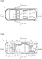
- Fig. 5 is a plan view schematically showing the arrangement of devices disposed on the floor panel 100.
- a vehicle on-board charger 40, a junction box 41, and a DC/DC converter 42 are disposed on the floor panel 100.
- the vehicle on-board charger 40, the junction box 41, and the DC/DC converter 42 are the high-voltage components HVC.
- the vehicle on-board charger 40 includes a cooling air inlet 63.
- the DC/DC converter 42 also includes a cooling air inlet 63.
- the two cooling air inlets 63 each open outward in the vehicle width direction.
- first slide rails 45 extending in the vehicle front-rear direction are disposed rearward of the high-voltage components HVC.
- second slide rails 46 extending in the vehicle front-rear direction are disposed rearward of the first slide rails 45.
- the first slide rails 45 are all disposed on the floor panel 100.
- Two of the four second slide rails 46 at the center in the vehicle width direction are disposed on the floor panel 100.
- the remaining two second slide rails 46 are disposed on the side surfaces of the vehicle 1 in the passenger compartment 16.
- the second-row seats 31 are disposed on the first slide rails 45.
- the second-row seats 31 are configured to be slidable in the vehicle front-rear direction along the first slide rails 45.
- the third-row seats 32 are disposed on the second slide rails 46.
- the third-row seats 32 are configured to be slidable in the vehicle front-rear direction along the second slide rails 46.
- Fig. 6 is a plan view schematically showing the arrangement of devices disposed under the floor panel 100.
- the plug-in hybrid electric vehicle 1 is divided into a right area RA and a left area LA with a center line CL, indicating the center in the vehicle width direction, serving as a boundary.
- the battery 50 is disposed so as to extend over both the right area RA and the left area LA.
- the battery 50 is disposed closer to the left side of the vehicle 1 than to the right side.
- a center of gravity 51 of the battery 50 is positioned in the left area LA. That is, the battery 50 is offset in the vehicle width direction so that the center of gravity 51 of the battery 50 is displaced from the center line CL in the vehicle width direction.
- the plug-in hybrid electric vehicle 1 includes the guide rails 11, which are located under the floor panel 100 and slidably support the sliding doors 4.
- the guide rails 11 are arranged so as to overlap with a part of the battery 50 in the vehicle front-rear direction.
- Each guide rail 11 includes a curved portion 13 that extends forward so as to curve inward in the vehicle width direction. When the sliding door 4 is closed, the sliding door 4 is pulled inward in the vehicle width direction along the curved portion 13 of the guide rail 11.
- An exhaust pipe 54 configured to guide exhaust gas from the engine 21 rearward is disposed under the floor panel 100.
- the exhaust pipe 54 connects the engine 21 to the muffler 53.
- the exhaust pipe 54 is disposed closer to the right side of the vehicle 1 than to the left side.
- the exhaust pipe 54 is disposed in the right area RA of the vehicle 1.
- the exhaust pipe 54 is disposed toward the side opposite to the side toward which the battery 50 is disposed in the vehicle width direction.
- the exhaust pipe 54 is disposed between the battery 50 and the guide rail 11 in the vehicle width direction.
- the exhaust pipe 54 is bent outward in the vehicle width direction along the curved portion 13 of the corresponding guide rail 11.
- the fuel tank 52 is disposed rearward of the battery 50.
- the fuel tank 52 is connected to the fuel inlet 17 via a fuel supply pipe 62.
- a fuel vapor recovery device 55 is disposed rearward of the rear-wheel drive motor-generator MGR and to a side of the muffler 53 in the vehicle width direction.
- the fuel vapor recovery device 55 is a canister that adsorbs fuel vapor gas generated inside the fuel tank 52.
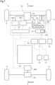
- Fig. 7 schematically shows a configuration of a drive system and a configuration of an electric system in the plug-in hybrid electric vehicle 1 of the present embodiment.
- the second motor-generator MG2 is connected to the battery 50 via the power control unit 22.
- the second motor-generator MG2 is coupled to the front wheels 14 via the speed reduction mechanism 24.
- the rotational power of the second motor-generator MG2 is transmitted to the front wheels 14 via the speed reduction mechanism 24, which is a power transmission mechanism.
- the second motor-generator MG2 acts as a drive motor.
- the engine 21 is connected to the front wheels 14 via the power split mechanism 23 and the speed reduction mechanism 24. Like the speed reduction mechanism 24, the power split mechanism 23 is also a power transmission mechanism. The rotational power of the engine 21 is transmitted to the front wheels 14 via the power transmission mechanisms.
- the first motor-generator MG1 is coupled to the power split mechanism 23.
- the first motor-generator MG1 is a three-phase AC motor-generator.
- the power split mechanism 23 is a planetary gear mechanism capable of splitting the driving force among the engine 21, the first motor-generator MG1, and the front wheels 14.
- the first motor-generator MG1 generates electric power by receiving the driving force of the engine 21 and/or the driving force from the front wheels 14.
- the first motor-generator MG1 acts as a starter to drive the crankshaft, which is the output shaft of the engine 21, when initiating the engine 21.
- the first motor-generator MG1 acts as an electric motor that generates a driving force in response to supply of electric power from the battery 50.
- the first motor-generator MG1 acts as a drive motor.
- the first motor-generator MG1 and the second motor-generator MG2 are connected to the battery 50 via the power control unit 22.
- AC power generated by the first motor-generator MG1 is converted into DC power by the power control unit 22, and the battery 50 is charged with the DC power.
- the power control unit 22 acts as an inverter.
- the DC power of the battery 50 is converted into AC power by the power control unit 22, and supplied to the second motor-generator MG2.
- the second motor-generator MG2 When the plug-in hybrid electric vehicle 1 is decelerated, the second motor-generator MG2 generates electric power using the driving force from the front wheels 14.
- the battery 50 is charged with the electric power generated by the second motor-generator MG2.
- the plug-in hybrid electric vehicle 1 performs charging through regenerative braking.
- the second motor-generator MG2 acts as a power generator.
- AC power generated by the second motor-generator MG2 is converted into DC power by the power control unit 22, and the battery 50 is charged with the DC power.
- the rear-wheel drive motor-generator MGR is connected to the battery 50 via the power control unit 22.
- the rear-wheel drive motor-generator MGR is coupled to the rear wheels 15 via the rear-wheel speed reduction mechanism 56.
- the DC power of the battery 50 is converted into AC power by the power control unit 22, and supplied to the rear-wheel drive motor-generator MGR.
- the rear-wheel drive motor-generator MGR is an electric motor that drives the rear wheels 15 by using electric power supplied from the battery 50. In other words, the rear-wheel drive motor-generator MGR acts as a drive motor.
- the rear-wheel drive motor-generator MGR When the plug-in hybrid electric vehicle 1 is decelerated, the rear-wheel drive motor-generator MGR generates electric power using the driving force from the rear wheels 15. The battery 50 is charged with electric power generated by the rear-wheel drive motor-generator MGR. In this case, the rear-wheel drive motor-generator MGR acts as a generator. AC power generated by the rear-wheel drive motor-generator MGR is converted into DC power by the power control unit 22, and the battery 50 is charged with the DC power.
- the plug-in hybrid electric vehicle 1 includes the vehicle on-board charger 40, the junction box 41, and the DC/DC converter 42 as the high-voltage components HVC. Further, the plug-in hybrid electric vehicle 1 includes the first charging port 18 and the second charging port 19 as charging ports into which charging plugs are inserted from the outside of the vehicle 1.
- the first charging port 18 is used for standard charging, which is performed using an AC power supply such as 100 V or 200 V.
- the second charging port 19 is used for fast charging with a high-voltage DC power supply, such as 50 kW.
- the first charging port 18 and the second charging port 19 are disposed on a side surface of the vehicle 1 and forward of the front door 2.
- the vehicle on-board charger 40 is connected to the first charging port 18 via a wire harness.
- the vehicle on-board charger 40 charges the battery 50 by converting AC power input from an AC power supply connected to the first charging port 18 into DC power and outputting the DC power. That is, the plug-in hybrid electric vehicle 1 can use an AC power supply as an external electrical power supply for charging the battery 50.
- the junction box 41 has a feature of distributing electric power from the battery 50 to multiple devices. For example, DC power from the battery 50 is supplied to the DC/DC converter 42, the air conditioner 57, and the water heater 58 via the junction box 41.
- the air conditioner 57 performs air conditioning of the passenger compartment 16 using the electric power supplied from the battery 50.
- the water heater 58 heats water into hot water using the electric power supplied from the battery 50 and uses the heated water as a heat source of the air conditioner 57.
- the junction box 41 is connected to the second charging port 19 via a wire harness.
- a DC power supply is connected to the second charging port 19.
- the DC power input from the DC power supply connected to the second charging port 19 is supplied to the battery 50 via the junction box 41. That is, the plug-in hybrid electric vehicle 1 can use a DC power supply as an external electrical power supply for charging the battery 50.
- the DC/DC converter 42 decreases the voltage of the battery 50 and supplies the decreased voltage to multiple auxiliary devices.
- the auxiliary devices include an electric power steering system 59 and an electric oil pump 60 disposed in the engine compartment 20.
- the electric power steering system 59 is a mechanism that assists the driver's steering operation.
- the electric oil pump 60 is a mechanism that draws lubricating oil and uses the lubricating oil to lubricate the engine 21.
- the battery 50 needs to be reduced in size to be disposed under the floor panel 100. Also, achieving a low floor design may become difficult. On the other hand, if the high-voltage components HVC are disposed above the floor panel 100, it is possible that a flat floor design cannot be achieved depending on the position at which the high-voltage components HVC are disposed.
- the high-voltage components HVC are disposed above the floor panel 100, it is possible to have a space for mounting a relatively large battery 50 under the floor panel 100 without raising the height of the floor panel 100. Further, since the high-voltage components HVC are disposed below the first-row seats 30, the floor on which the second-row seats 31 are disposed can be made flat.
- the high-voltage components HVC may be disposed at a position that is not above the battery 50 as long as the high-voltage components HVC are disposed below the first-row seats 30 and above the floor panel 100. That is, the battery 50 does not necessarily need to be disposed below the high-voltage components HVC.
- the plug-in hybrid electric vehicle 1 does not necessarily need to include the junction box 41.
- the plug-in hybrid electric vehicle 1 does not necessarily need to include the junction box 41.
- the vehicle on-board charger 40 may be disposed between the junction box 41 and the DC/DC converter 42.
- the high-voltage components HVC do not necessarily need to be connected to the battery 50 by wire harnesses.
- the high-voltage components HVC may be connected to the battery 50 by a bus bar.
- the DC/DC converter 42 does not necessarily need to be connected to the junction box 41 by a wire harness.
- the DC/DC converter 42 may be connected to the junction box 41 by a bus bar.
- junction box 41, the DC/DC converter 42, and the vehicle on-board charger 40 do not necessarily need to be arranged in the vehicle width direction as long as the junction box 41, the DC/DC converter 42, and the vehicle on-board charger 40 are arranged below the first-row seats 30 and above the floor panel 100.
- the junction box 41, the DC/DC converter 42, and the vehicle on-board charger 40 may be stacked in the height direction of the vehicle 1.
- the plug-in hybrid electric vehicle 1 does not necessarily need to include the first cross member 43 at a position forward of the high-voltage components HVC.
- the plug-in hybrid electric vehicle 1 does not necessarily need to include any cross members.
- the high-voltage components HVC do not necessarily need to be disposed between two cross members.
- the high-voltage components HVC do not necessarily need to include the cooling air inlets 63.
- the vehicle on-board charger 40 does not necessarily need to include the cooling air inlet 63.
- the DC/DC converter 42 does not necessarily need to include the cooling air inlet 63.
- each cooling air inlet 63 provided in the vehicle on-board charger 40 and the DC/DC converter 42 do not necessarily need to be directed outward in the vehicle width direction.
- each cooling air inlet 63 may open toward the front of the vehicle 1.
- each cooling air inlet 63 may open toward the rear of the vehicle 1.
Landscapes
- Engineering & Computer Science (AREA)
- Mechanical Engineering (AREA)
- Transportation (AREA)
- Chemical & Material Sciences (AREA)
- Combustion & Propulsion (AREA)
- Power Engineering (AREA)
- Aviation & Aerospace Engineering (AREA)
- Life Sciences & Earth Sciences (AREA)
- Sustainable Development (AREA)
- Sustainable Energy (AREA)
- Hybrid Electric Vehicles (AREA)
- Electric Propulsion And Braking For Vehicles (AREA)
- Cooling, Air Intake And Gas Exhaust, And Fuel Tank Arrangements In Propulsion Units (AREA)
- Arrangement Or Mounting Of Propulsion Units For Vehicles (AREA)
Abstract
A minivan-type plug-in hybrid electric vehicle includes a fuel tank, a battery, an exhaust pipe, and a high-voltage component that receives a high voltage. The plug-in hybrid electric vehicle further includes a first-row seat and a second-row seat, which are disposed on a floor panel forming a floor surface of a passenger compartment. In the vehicle front-rear direction, the first-row seat is positioned rearward of the front wheels, and the second-row seat is positioned rearward of the first-row seat and forward of the rear wheels. The second-row seat is slidable on the floor panel in the vehicle front-rear direction. The battery, the fuel tank, and the exhaust pipe are disposed below the floor panel. The high-voltage component is disposed under the first-row seat and above the floor panel.
Description
- The present disclosure relates to a plug-in hybrid electric vehicle that can be connected to an external electrical power supply to charge its battery.
-
Japanese Laid-Open Patent Publication No. 2021-160519 - A minivan-type vehicle is equipped with a sliding seat as the second-row seat and a sliding door. The sliding seat is capable of sliding along the floor in the vehicle's longitudinal direction. To ensure a sufficient sliding range for the sliding seat, long slide rails must be installed on the floor. Therefore, in a minivan-type vehicle, it is desirable for the floor behind the first-row seats to have a low, flat structure.
- A plug-in hybrid electric vehicle, which can charge its battery by connecting to an external electrical power supply, requires a larger battery than a hybrid electric vehicle that does not have such a configuration.
- Accordingly, in a minivan-type plug-in hybrid electric vehicle, it is necessary to examine the arrangement of high-voltage components that allows for both the installation of a large battery and a low, flat floor to ensure a spacious passenger compartment.
- This Summary is provided to introduce a selection of concepts in a simplified form that are further described below in the Detailed Description. This Summary is not intended to identify key features or essential features of the claimed subject matter, nor is it intended to be used as an aid in determining the scope of the claimed subject matter.
- A plug-in hybrid electric vehicle of one aspect of the present disclosure is a minivan-type plug-in hybrid electric vehicle in which a passenger compartment and a cargo space are not separated by a partition. The plug-in hybrid electric vehicle includes power sources including an engine and a motor, a fuel tank configured to store fuel to be supplied to the engine, a battery configured to store electric power to be supplied to the motor, a high-voltage component configured to receive a high voltage, a vehicle on-board charger configured to charge the battery with power supplied from outside of the plug-in hybrid electric vehicle, a power transmission mechanism configured to transmit rotational power of the engine and the motor to front wheels, an inverter configured to drive the motor, an exhaust pipe configured to guide exhaust gas from the engine rearward in the vehicle front-rear direction, a first-row seat arranged on a floor panel that forms a floor surface of the passenger compartment, and a second-row seat disposed on the floor panel so as to be positioned rearward of the first-row seat in the vehicle front-rear direction. The engine, the motor, the power transmission mechanism, and the inverter are disposed in the engine compartment. In the vehicle front-rear direction, the first-row seat is positioned rearward of the front wheels, and the second-row seat is positioned forward of the rear wheels. The second-row seat is configured to be slidable on the floor panel in the vehicle front-rear direction. The battery, the fuel tank, and the exhaust pipe are disposed under the floor panel. The high-voltage component is disposed under the first-row seat and above the floor panel.
- Other features and aspects will be apparent from the following detailed description, the drawings, and the claims.
-
-
Fig. 1 is a schematic diagram of a minivan-type plug-in hybrid electric vehicle according to an embodiment. -
Fig. 2 is a plan view of a sliding door provided in the plug-in hybrid electric vehicle ofFig. 1 . -
Fig. 3 is a schematic diagram of an internal structure of the plug-in hybrid electric vehicle shown inFig. 1 . -
Fig. 4 is a schematic diagram of an arrangement of seats in the plug-in hybrid electric vehicle shown inFig. 1 . -
Fig. 5 is a schematic diagram of an arrangement of devices disposed on a floor panel in the plug-in hybrid electric vehicle shown inFig. 1 . -
Fig. 6 is a schematic diagram of an arrangement of devices disposed under the floor panel in the plug-in hybrid electric vehicle shown inFig. 1 . -
Fig. 7 is a schematic diagram of a configuration of a drive system and a configuration of an electric system in the plug-in hybrid electric vehicle shown inFig. 1 . - Throughout the drawings and the detailed description, the same reference numerals refer to the same elements. The drawings may not be to scale, and the relative size, proportions, and depiction of elements in the drawings may be exaggerated for clarity, illustration, and convenience.
- This description provides a comprehensive understanding of the methods, apparatuses, and/or systems described. Modifications and equivalents of the methods, apparatuses, and/or systems described are apparent to one of ordinary skill in the art. Sequences of operations are exemplary, and may be changed as apparent to one of ordinary skill in the art, with the exception of operations necessarily occurring in a certain order. Descriptions of acts and constructions that are well known to one of ordinary skill in the art may be omitted.
- Exemplary embodiments may have different forms, and are not limited to the examples described. However, the examples described are thorough and complete, and convey the full scope of the disclosure to one of ordinary skill in the art.
- In this specification, "at least one of A and B" should be understood to mean "only A, only B, or both A and B."
- A plug-in hybrid
electric vehicle 1 according to one embodiment will now be described with reference toFigs. 1 to 7 . In the following description, terms related to orientations or directions, such as "front", "rear", "upper", "lower", "right", and "left", are defined based on the plug-in hybridelectric vehicle 1. -
Fig. 1 is a schematic diagram of the plug-in hybridelectric vehicle 1 according to the present embodiment. The plug-in hybridelectric vehicle 1 has a left side surface, which is one of a first side surface and a second side surface, and a right side surface, which is the other of the first side surface and the second side surface. As shown inFig. 1 , the plug-in hybridelectric vehicle 1 includes afront door 2, anopening 3, and a slidingdoor 4, which are on the left side surface. Likewise, the plug-in hybridelectric vehicle 1 includes afront door 2, an opening 3, and a slidingdoor 4 on the right side surface. Acharging lid 61 is disposed on the left side surface of the plug-in hybridelectric vehicle 1 and forward of thefront door 2. Afirst charging port 18 and asecond charging port 19, which will be discussed below, are disposed inside thecharging lid 61. - The
opening 3 is opened and closed by the slidingdoor 4, which moves in the vehicle front-rear direction. A step panel 5 is disposed in a lower portion of theopening 3. The step panel 5 is disposed below afloor panel 100, which forms a floor surface of the plug-in hybridelectric vehicle 1. Aguide rail 11 extending in the vehicle front-rear direction is fixed to a lower surface of the step panel 5. A front end of theguide rail 11 is positioned rearward of afront wheel 14. A rear end of theguide rail 11 is positioned forward of arear wheel 15. - As shown in
Fig. 2 , thefuel inlet 17 is disposed on the left side surface of the plug-in hybridelectric vehicle 1 and rearward of the slidingdoor 4. Anupper rail 7, acenter rail 9, and aguide rail 11 are disposed around theopening 3. Theupper rail 7 is disposed above theopening 3. Theguide rail 11 is disposed below theopening 3. Thecenter rail 9 is disposed rearward of the opening 3 on the side surface of thevehicle 1. The position of thecenter rail 9 in the vehicle height direction is below theupper rail 7 and above theguide rail 11. - The sliding
door 4 includes a slidingdoor body 6, anupper hinge unit 8, acenter hinge unit 10, and aguide hinge unit 12. Theupper hinge unit 8 and theguide hinge unit 12 are fixed to parts of the slidingdoor body 6 near the front end in a vehicle length direction. Thecenter hinge unit 10 is fixed to a part of the slidingdoor body 6 near the rear end in the vehicle length direction. The vehicle length direction coincides with the vehicle front-rear direction. - The
upper hinge unit 8 is fixed to an upper end portion of the slidingdoor body 6. Theguide hinge unit 12 is fixed to a lower end portion of the slidingdoor body 6. Thecenter hinge unit 10 is fixed to a central portion of the slidingdoor body 6 in the vertical direction. - The
upper hinge unit 8 is movably supported by theupper rail 7. Thecenter hinge unit 10 is movably supported by thecenter rail 9. Theguide hinge unit 12 is movably supported by theguide rail 11. Thus, theupper hinge unit 8, thecenter hinge unit 10, and theguide hinge unit 12 connect the slidingdoor body 6 to the side surface of thevehicle 1. Theupper hinge unit 8 moves along theupper rail 7. Thecenter hinge unit 10 moves along thecenter rail 9. Theguide hinge unit 12 moves along theguide rail 11. The slidingdoor body 6 thus moves relative to the side surface of thevehicle 1. Theupper rail 7, thecenter rail 9, and theguide rail 11 define the moving direction of the slidingdoor 4. -
Fig. 3 is a side view schematically showing an internal structure of the plug-in hybridelectric vehicle 1. As shown inFig. 3 , the plug-in hybridelectric vehicle 1 is a minivan-type vehicle in which apassenger compartment 16 and a cargo space are not separated by a partition. The plug-in hybridelectric vehicle 1 includes anengine compartment 20 forward of thepassenger compartment 16. Theengine compartment 20 accommodates, as power sources, anengine 21, a first motor-generator MG1, a second motor-generator MG2, apower control unit 22, apower split mechanism 23, and aspeed reduction mechanism 24. - First-
row seats 30, second-row seats 31, and third-row seats 32 are disposed on thefloor panel 100. The second-row seats 31 are positioned rearward of the first-row seats 30. In the vehicle side view, the first-row seats 30 are positioned rearward of thefront wheels 14. In the vehicle side view, the second-row seats 31 are positioned forward of therear wheel 15. -
Fig. 4 is a plan view schematically showing the arrangement of the seats. As shown inFig. 4 , the first-row seats 30 include a driver's seat and a front passenger seat. The second-row seats 31 include two independent seats. The third-row seats 32 are positioned rearward of the second-row seats 31. - As shown in
Fig. 3 , high-voltage components HVC are disposed below the first-row seats 30 and above thefloor panel 100. Details of the high-voltage components HVC will be described later. - The plug-in hybrid
electric vehicle 1 includes afirst cross member 43 and asecond cross member 44 below the first-row seats 30 and above thefloor panel 100. Thefirst cross member 43 and thesecond cross member 44 are frame members extending in the vehicle width direction. Thefirst cross member 43 is disposed forward of the high-voltage components HVC. Thesecond cross member 44 is disposed rearward of the high-voltage components HVC. That is, thefirst cross member 43 and thesecond cross member 44 are disposed such that the high-voltage components HVC are located in between. - A
battery 50, afuel tank 52, amuffler 53, a rear-wheel drive motor-generator MGR, and a rear-wheelspeed reduction mechanism 56 are disposed under thefloor panel 100. Thebattery 50 is configured to store electric power to be supplied to the first motor-generator MG1, the second motor-generator MG2, and the rear-wheel drive motor-generator MGR. Thefuel tank 52 is configured to store fuel to be supplied to theengine 21. Themuffler 53 is configured to reduce exhaust noise. - The
fuel tank 52 is disposed rearward of thebattery 50. The rear-wheel drive motor-generator MGR is disposed rearward of thefuel tank 52. Themuffler 53 is disposed rearward of the rear-wheel drive motor-generator MGR. - The high-voltage components HVC are disposed on the
battery 50. -
Fig. 5 is a plan view schematically showing the arrangement of devices disposed on thefloor panel 100. As shown inFig. 5 , a vehicle on-board charger 40, ajunction box 41, and a DC/DC converter 42 are disposed on thefloor panel 100. The vehicle on-board charger 40, thejunction box 41, and the DC/DC converter 42 are the high-voltage components HVC. - The vehicle on-
board charger 40 includes a coolingair inlet 63. The DC/DC converter 42 also includes a coolingair inlet 63. The twocooling air inlets 63 each open outward in the vehicle width direction. - Four first slide rails 45 extending in the vehicle front-rear direction are disposed rearward of the high-voltage components HVC. Four second slide rails 46 extending in the vehicle front-rear direction are disposed rearward of the first slide rails 45. The first slide rails 45 are all disposed on the
floor panel 100. Two of the four second slide rails 46 at the center in the vehicle width direction are disposed on thefloor panel 100. The remaining two second slide rails 46 are disposed on the side surfaces of thevehicle 1 in thepassenger compartment 16. - As shown in
Fig. 4 , the second-row seats 31 are disposed on the first slide rails 45. The second-row seats 31 are configured to be slidable in the vehicle front-rear direction along the first slide rails 45. The third-row seats 32 are disposed on the second slide rails 46. The third-row seats 32 are configured to be slidable in the vehicle front-rear direction along the second slide rails 46. -
Fig. 6 is a plan view schematically showing the arrangement of devices disposed under thefloor panel 100. The plug-in hybridelectric vehicle 1 is divided into a right area RA and a left area LA with a center line CL, indicating the center in the vehicle width direction, serving as a boundary. - The
battery 50 is disposed so as to extend over both the right area RA and the left area LA. Thebattery 50 is disposed closer to the left side of thevehicle 1 than to the right side. A center ofgravity 51 of thebattery 50 is positioned in the left area LA. That is, thebattery 50 is offset in the vehicle width direction so that the center ofgravity 51 of thebattery 50 is displaced from the center line CL in the vehicle width direction. - The plug-in hybrid
electric vehicle 1 includes the guide rails 11, which are located under thefloor panel 100 and slidably support the slidingdoors 4. The guide rails 11 are arranged so as to overlap with a part of thebattery 50 in the vehicle front-rear direction. Eachguide rail 11 includes acurved portion 13 that extends forward so as to curve inward in the vehicle width direction. When the slidingdoor 4 is closed, the slidingdoor 4 is pulled inward in the vehicle width direction along thecurved portion 13 of theguide rail 11. - An
exhaust pipe 54 configured to guide exhaust gas from theengine 21 rearward is disposed under thefloor panel 100. Theexhaust pipe 54 connects theengine 21 to themuffler 53. Theexhaust pipe 54 is disposed closer to the right side of thevehicle 1 than to the left side. Theexhaust pipe 54 is disposed in the right area RA of thevehicle 1. Theexhaust pipe 54 is disposed toward the side opposite to the side toward which thebattery 50 is disposed in the vehicle width direction. Theexhaust pipe 54 is disposed between thebattery 50 and theguide rail 11 in the vehicle width direction. Theexhaust pipe 54 is bent outward in the vehicle width direction along thecurved portion 13 of thecorresponding guide rail 11. - The
fuel tank 52 is disposed rearward of thebattery 50. Thefuel tank 52 is connected to thefuel inlet 17 via afuel supply pipe 62. - A fuel
vapor recovery device 55 is disposed rearward of the rear-wheel drive motor-generator MGR and to a side of themuffler 53 in the vehicle width direction. The fuelvapor recovery device 55 is a canister that adsorbs fuel vapor gas generated inside thefuel tank 52. -
Fig. 7 schematically shows a configuration of a drive system and a configuration of an electric system in the plug-in hybridelectric vehicle 1 of the present embodiment. - As shown in
Fig. 7 , the second motor-generator MG2 is connected to thebattery 50 via thepower control unit 22. The second motor-generator MG2 is coupled to thefront wheels 14 via thespeed reduction mechanism 24. The rotational power of the second motor-generator MG2 is transmitted to thefront wheels 14 via thespeed reduction mechanism 24, which is a power transmission mechanism. In other words, the second motor-generator MG2 acts as a drive motor. - The
engine 21 is connected to thefront wheels 14 via thepower split mechanism 23 and thespeed reduction mechanism 24. Like thespeed reduction mechanism 24, thepower split mechanism 23 is also a power transmission mechanism. The rotational power of theengine 21 is transmitted to thefront wheels 14 via the power transmission mechanisms. The first motor-generator MG1 is coupled to thepower split mechanism 23. The first motor-generator MG1 is a three-phase AC motor-generator. Thepower split mechanism 23 is a planetary gear mechanism capable of splitting the driving force among theengine 21, the first motor-generator MG1, and thefront wheels 14. - The first motor-generator MG1 generates electric power by receiving the driving force of the
engine 21 and/or the driving force from thefront wheels 14. The first motor-generator MG1 acts as a starter to drive the crankshaft, which is the output shaft of theengine 21, when initiating theengine 21. In this case, the first motor-generator MG1 acts as an electric motor that generates a driving force in response to supply of electric power from thebattery 50. In other words, the first motor-generator MG1 acts as a drive motor. - The first motor-generator MG1 and the second motor-generator MG2 are connected to the
battery 50 via thepower control unit 22. AC power generated by the first motor-generator MG1 is converted into DC power by thepower control unit 22, and thebattery 50 is charged with the DC power. In other words, thepower control unit 22 acts as an inverter. - The DC power of the
battery 50 is converted into AC power by thepower control unit 22, and supplied to the second motor-generator MG2. When the plug-in hybridelectric vehicle 1 is decelerated, the second motor-generator MG2 generates electric power using the driving force from thefront wheels 14. Thebattery 50 is charged with the electric power generated by the second motor-generator MG2. In other words, the plug-in hybridelectric vehicle 1 performs charging through regenerative braking. In this case, the second motor-generator MG2 acts as a power generator. AC power generated by the second motor-generator MG2 is converted into DC power by thepower control unit 22, and thebattery 50 is charged with the DC power. - The rear-wheel drive motor-generator MGR is connected to the
battery 50 via thepower control unit 22. The rear-wheel drive motor-generator MGR is coupled to therear wheels 15 via the rear-wheelspeed reduction mechanism 56. The DC power of thebattery 50 is converted into AC power by thepower control unit 22, and supplied to the rear-wheel drive motor-generator MGR. The rear-wheel drive motor-generator MGR is an electric motor that drives therear wheels 15 by using electric power supplied from thebattery 50. In other words, the rear-wheel drive motor-generator MGR acts as a drive motor. - When the plug-in hybrid
electric vehicle 1 is decelerated, the rear-wheel drive motor-generator MGR generates electric power using the driving force from therear wheels 15. Thebattery 50 is charged with electric power generated by the rear-wheel drive motor-generator MGR. In this case, the rear-wheel drive motor-generator MGR acts as a generator. AC power generated by the rear-wheel drive motor-generator MGR is converted into DC power by thepower control unit 22, and thebattery 50 is charged with the DC power. - As shown in
Fig. 7 , the plug-in hybridelectric vehicle 1 includes the vehicle on-board charger 40, thejunction box 41, and the DC/DC converter 42 as the high-voltage components HVC. Further, the plug-in hybridelectric vehicle 1 includes the first chargingport 18 and the second chargingport 19 as charging ports into which charging plugs are inserted from the outside of thevehicle 1. The first chargingport 18 is used for standard charging, which is performed using an AC power supply such as 100 V or 200 V. The second chargingport 19 is used for fast charging with a high-voltage DC power supply, such as 50 kW. As shown inFig. 1 , the first chargingport 18 and the second chargingport 19 are disposed on a side surface of thevehicle 1 and forward of thefront door 2. - As shown in
Fig. 7 , the vehicle on-board charger 40 is connected to thebattery 50 via a wire harness. Thejunction box 41 is connected to thebattery 50 via a wire harness. The DC/DC converter 42 is connected to thejunction box 41 via a wire harness. - The vehicle on-
board charger 40 is connected to the first chargingport 18 via a wire harness. The vehicle on-board charger 40 charges thebattery 50 by converting AC power input from an AC power supply connected to the first chargingport 18 into DC power and outputting the DC power. That is, the plug-in hybridelectric vehicle 1 can use an AC power supply as an external electrical power supply for charging thebattery 50. - The
junction box 41 has a feature of distributing electric power from thebattery 50 to multiple devices. For example, DC power from thebattery 50 is supplied to the DC/DC converter 42, theair conditioner 57, and thewater heater 58 via thejunction box 41. - The
air conditioner 57 performs air conditioning of thepassenger compartment 16 using the electric power supplied from thebattery 50. Thewater heater 58 heats water into hot water using the electric power supplied from thebattery 50 and uses the heated water as a heat source of theair conditioner 57. - The
junction box 41 is connected to the second chargingport 19 via a wire harness. A DC power supply is connected to the second chargingport 19. The DC power input from the DC power supply connected to the second chargingport 19 is supplied to thebattery 50 via thejunction box 41. That is, the plug-in hybridelectric vehicle 1 can use a DC power supply as an external electrical power supply for charging thebattery 50. - The DC/
DC converter 42 decreases the voltage of thebattery 50 and supplies the decreased voltage to multiple auxiliary devices. The auxiliary devices include an electricpower steering system 59 and anelectric oil pump 60 disposed in theengine compartment 20. The electricpower steering system 59 is a mechanism that assists the driver's steering operation. Theelectric oil pump 60 is a mechanism that draws lubricating oil and uses the lubricating oil to lubricate theengine 21. - If the high-voltage components HVC are disposed under the
floor panel 100, thebattery 50 needs to be reduced in size to be disposed under thefloor panel 100. Also, achieving a low floor design may become difficult. On the other hand, if the high-voltage components HVC are disposed above thefloor panel 100, it is possible that a flat floor design cannot be achieved depending on the position at which the high-voltage components HVC are disposed. - In the present embodiment, since the high-voltage components HVC are disposed above the
floor panel 100, it is possible to have a space for mounting a relativelylarge battery 50 under thefloor panel 100 without raising the height of thefloor panel 100. Further, since the high-voltage components HVC are disposed below the first-row seats 30, the floor on which the second-row seats 31 are disposed can be made flat. -
- (1) The plug-in hybrid
electric vehicle 1 has a relatively low and flat floor and a relatively large passenger compartment while allowing thelarge battery 50 to be mounted. - (2) The high-voltage components HVC mounted on the plug-in hybrid
electric vehicle 1 are connected to thebattery 50 via a wire harness. The high-voltage components HVC are disposed on thebattery 50. The high-voltage components HVC include components that send and receive electric power to and from thebattery 50 via wire harnesses. Since the high-voltage components HVC are disposed on thebattery 50, relatively short wire harnesses can be used to connect the high-voltage components HVC and thebattery 50 to each other. The use of relatively short wire harnesses reduces the weight of the above-described plug-in hybridelectric vehicle 1. - (3) The high-voltage components HVC include the vehicle on-
board charger 40, thejunction box 41 that distributes the current from thebattery 50, and the DC/DC converter 42 that converts the voltage of the electric power supplied from thebattery 50. The vehicle on-board charger 40, thejunction box 41, and the DC/DC converter 42 are disposed above thebattery 50 and under the first-row seats 30 in a state of being arranged in the vehicle width direction. The vehicle on-board charger 40 is connected to thebattery 50 by a wire harness. Thejunction box 41 is connected to thebattery 50 by a wire harness. The DC/DC converter 42 is connected to thejunction box 41 by a wire harness. With this configuration, the high-voltage components HVC are consolidated, allowing for efficient connections between the high-voltage components HVC and thebattery 50, as well as efficient interconnections among the high-voltage components HVC themselves. - (4) The high-voltage components HVC include the
junction box 41. Thejunction box 41 is disposed on thebattery 50. The wire harness that connects thejunction box 41 to thebattery 50 receives a relatively high voltage. Since thejunction box 41 is disposed on thebattery 50 in the above-described configuration, the wire harness connecting thejunction box 41 to thebattery 50 can be shortened. This reduces the power loss in the wire harness that connects thejunction box 41 to thebattery 50. - (5) The high-voltage components HVC include the DC/
DC converter 42. The DC/DC converter 42 is disposed on thebattery 50. The wire harness that connects the DC/DC converter 42 to thebattery 50 receives a relatively high voltage. Since the DC/DC converter 42 is disposed on thebattery 50 in the above-described configuration, the wire harness connecting the DC/DC converter 42 to thebattery 50 can be shortened. This reduces the power loss in the wire harness that connects the DC/DC converter 42 to thebattery 50. - (6) The high-voltage components HVC include the vehicle on-
board charger 40. The vehicle on-board charger 40 is disposed on thebattery 50. Since the vehicle on-board charger 40 is disposed on thebattery 50 in the above-described configuration, the wire harness connecting the vehicle on-board charger 40 to thebattery 50 can be shortened. This reduces the power loss in the wire harness that connects the vehicle on-board charger 40 to thebattery 50. - (7) In the plug-in hybrid
electric vehicle 1, the vehicle on-board charger 40 is disposed to the side of thejunction box 41 in the vehicle width direction. The DC/DC converter 42 is disposed on a side of thejunction box 41 that is opposite to the vehicle on-board charger 40 in the vehicle width direction. The DC/DC converter 42 is connected to thejunction box 41 via a wire harness. Thus, if the DC/DC converter 42 is installed to the side of thejunction box 41, the wire harness connecting the DC/DC converter 42 to thejunction box 41 is shortened. Since the wire harness is shortened, the weight of the wire harness is reduced. This reduces the weight of the plug-in hybridelectric vehicle 1. Additionally, a shorter wire harness reduces power loss within the wire harness. Therefore, the above-described plug-in hybridelectric vehicle 1 reduces power loss in the wire harness that connects the DC/DC converter 42 to thejunction box 41. - (8) The plug-in hybrid
electric vehicle 1 includes thefirst cross member 43 and thesecond cross member 44, which extend in the vehicle width direction. Thefirst cross member 43 is positioned forward of the high-voltage components HVC. Thesecond cross member 44 is positioned rearward of the high-voltage components HVC. Thefirst cross member 43 and thesecond cross member 44 are disposed such that the high-voltage components HVC are located in between. The high-voltage components HVC, which receive a high voltage, are preferably protected from impacts. In the above-described plug-in hybridelectric vehicle 1, thefirst cross member 43 and thesecond cross member 44 are respectively disposed forward of and rearward of the high-voltage components HVC, such that the high-voltage components HVC are positioned between thefirst cross member 43 and thesecond cross member 44. Thus, an impact from the front of thevehicle 1 is absorbed by thefirst cross member 43 before reaching the high-voltage components HVC. An impact from the rear of thevehicle 1 is absorbed by thesecond cross member 44 before reaching the high-voltage components HVC. In this manner, the above-described plug-in hybridelectric vehicle 1 can protect the high-voltage components HVC from impacts from the front and rear of thevehicle 1. - (9) In the plug-in hybrid
electric vehicle 1, the high-voltage components HVC include the coolingair inlets 63. The coolingair inlets 63 of the high-voltage components HVC open outward in the vehicle width direction. If the coolingair inlets 63 open toward the front of thevehicle 1, an airflow is generated around the feet of occupants seated in the first-row seats 30. If the coolingair inlets 63 open toward the rear of thevehicle 1, an airflow is generated around the feet of occupants seated in the second-row seats 31. This airflow in either case may cause discomfort to the occupants. In the present embodiment, the likelihood of airflow being directed toward occupants' feet is reduced compared to a configuration in which the coolingair inlets 63 open toward the front or rear of thevehicle 1. Accordingly, the above-described plug-in hybridelectric vehicle 1 effectively cools the high-voltage components HVC while minimizing discomfort to occupants. - (10) In the plug-in hybrid
electric vehicle 1, the vehicle on-board charger 40 and the DC/DC converter 42 include the coolingair inlets 63. The coolingair inlet 63 of the vehicle on-board charger 40 and the coolingair inlet 63 of the DC/DC converter 42 both open outward in the vehicle width direction. The vehicle on-board charger 40 and the DC/DC converter 42 generate a larger amount of heat than thejunction box 41. In the present embodiment, the vehicle on-board charger 40 and the DC/DC converter 42, which generate a large amount of heat, are efficiently cooled. - The above-described embodiment may be modified as follows. The above-described embodiment and the following modifications can be combined as long as the combined modifications remain technically consistent with each other.
- The high-voltage components HVC may be disposed at a position that is not above the
battery 50 as long as the high-voltage components HVC are disposed below the first-row seats 30 and above thefloor panel 100. That is, thebattery 50 does not necessarily need to be disposed below the high-voltage components HVC. - The plug-in hybrid
electric vehicle 1 does not necessarily need to include thejunction box 41. For example, if thebattery 50 has a feature of distributing current, the plug-in hybridelectric vehicle 1 does not necessarily need to include thejunction box 41. - The vehicle on-
board charger 40 may be disposed between thejunction box 41 and the DC/DC converter 42. - The high-voltage components HVC do not necessarily need to be connected to the
battery 50 by wire harnesses. For example, the high-voltage components HVC may be connected to thebattery 50 by a bus bar. - The DC/
DC converter 42 does not necessarily need to be connected to thejunction box 41 by a wire harness. For example, the DC/DC converter 42 may be connected to thejunction box 41 by a bus bar. - The
junction box 41, the DC/DC converter 42, and the vehicle on-board charger 40 do not necessarily need to be arranged in the vehicle width direction as long as thejunction box 41, the DC/DC converter 42, and the vehicle on-board charger 40 are arranged below the first-row seats 30 and above thefloor panel 100. For example, thejunction box 41, the DC/DC converter 42, and the vehicle on-board charger 40 may be stacked in the height direction of thevehicle 1. - The plug-in hybrid
electric vehicle 1 does not necessarily need to include thefirst cross member 43 at a position forward of the high-voltage components HVC. - The plug-in hybrid
electric vehicle 1 does not necessarily need to include thesecond cross member 44 at a position rearward of the high-voltage components HVC. - The plug-in hybrid
electric vehicle 1 does not necessarily need to include any cross members. - The high-voltage components HVC do not necessarily need to be disposed between two cross members.
- The high-voltage components HVC do not necessarily need to include the cooling
air inlets 63. - The vehicle on-
board charger 40 does not necessarily need to include the coolingair inlet 63. - The DC/
DC converter 42 does not necessarily need to include the coolingair inlet 63. - The cooling
air inlets 63 provided in the vehicle on-board charger 40 and the DC/DC converter 42 do not necessarily need to be directed outward in the vehicle width direction. For example, each coolingair inlet 63 may open toward the front of thevehicle 1. Alternatively, each coolingair inlet 63 may open toward the rear of thevehicle 1. - Various changes in form and details may be made to the examples above without departing from the spirit and scope of the claims and their equivalents. The examples are for the sake of description only, and not for purposes of limitation. Descriptions of features in each example are to be considered as being applicable to similar features or aspects in other examples. Suitable results may be achieved if sequences are performed in a different order, and/or if components in a described system, architecture, device, or circuit are combined differently, and/or replaced or supplemented by other components or their equivalents. The scope of the disclosure is not defined by the detailed description, but by the claims and their equivalents. All variations within the scope of the claims and their equivalents are included in the disclosure.
Claims (10)
- A minivan-type plug-in hybrid electric vehicle (1) in which a passenger compartment (16) and a cargo space are not separated by a partition, the vehicle (1) comprising:an engine compartment (20) provided in front of the passenger compartment (16) in a vehicle front-rear direction;power sources including an engine (21) and a motor (MG1, MG2);a fuel tank (52) configured to store fuel to be supplied to the engine (21);a battery (50) configured to store electric power to be supplied to the motor (MG1, MG2);a high-voltage component (HVC) configured to receive a high voltage;a vehicle on-board charger (40) configured to charge the battery (50) with power supplied from outside of the plug-in hybrid electric vehicle (1);a power transmission mechanism (23, 24) configured to transmit rotational power of the engine (21) and the motor (MG1, MG2) to front wheels (14);an inverter (22) configured to drive the motor (MG1, MG2);an exhaust pipe (54) configured to guide exhaust gas from the engine (21) rearward in the vehicle front-rear direction;a first-row seat (30) arranged on a floor panel (100) that forms a floor surface of the passenger compartment (16); anda second-row seat (31) disposed on the floor panel (100) so as to be positioned rearward of the first-row seat (30) in the vehicle front-rear direction, whereinthe engine (21), the motor (MG1, MG2), the power transmission mechanism (23, 24), and the inverter (22) are disposed in the engine compartment (20),in the vehicle front-rear direction, the first-row seat (30) is positioned rearward of the front wheels (14), and the second-row seat (31) is positioned forward of the rear wheels (15),the second-row seat (31) is configured to be slidable on the floor panel (100) in the vehicle front-rear direction,the battery (50), the fuel tank (52), and the exhaust pipe (54) are disposed under the floor panel (100), andthe high-voltage component (HVC) is disposed under the first-row seat (30) and above the floor panel (100).
- The plug-in hybrid electric vehicle (1) according to claim 1, whereinthe high-voltage component (HVC) is connected to the battery (50) via a wire harness, andthe high-voltage component (HVC) is disposed above the battery (50).
- The plug-in hybrid electric vehicle (1) according to claim 2, wherein the high-voltage component (HVC) includes:a junction box (41) configured to distribute a current supplied from the battery (50);a converter (42) configured to convert a voltage of electric power supplied from the battery (50); anda vehicle on-board charger (40), andthe junction box (41), the converter (42), and the vehicle on-board charger (40) are disposed above the battery (50) and under the first-row seat (30) in a state of being arranged in a vehicle width direction.
- The plug-in hybrid electric vehicle (1) according to claim 2, wherein the high-voltage component (HVC) includes a junction box (41) configured to distribute a current supplied from the battery (50).
- The plug-in hybrid electric vehicle (1) according to claim 2, wherein the high-voltage component (HVC) includes a converter (42) configured to convert a voltage of electric power supplied from the battery (50), and
the converter (42) is disposed above the battery (50). - The plug-in hybrid electric vehicle (1) according to claim 2, wherein the high-voltage component (HVC) includes a vehicle on-board charger (40), and
the vehicle on-board charger (40) is disposed above the battery (50). - The plug-in hybrid electric vehicle (1) according to claim 3, wherein the vehicle on-board charger (40) is disposed to a side of the junction box (41) in the vehicle width direction,the converter (42) is disposed on a side of the junction box (41) that is opposite to the vehicle on-board charger (40) in the vehicle width direction, andthe converter (42) is connected to the junction box (41) by a wire harness.
- The plug-in hybrid electric vehicle (1) according to any one of claims 1 to 7, further comprising multiple cross members (43, 44) extending in a vehicle width direction,
wherein two of the cross members (43, 44) are respectively positioned forward of and rearward of the high-voltage component (HVC) in the vehicle front-rear direction such that the high-voltage components (HVC) are positioned between the two cross members (43, 44). - The plug-in hybrid electric vehicle (1) according to claim 1, wherein the high-voltage component (HVC) includes an air inlet (63) for cooling, and the air inlet (63) opens outward in the vehicle width direction.
- The plug-in hybrid electric vehicle (1) according to claim 7, wherein the vehicle on-board charger (40) and the converter (42) each include an air inlet (63) for cooling, and
the air inlet (63) of the vehicle on-board charger (40) and the air inlet (63) of the converter (42) both open outward in the vehicle width direction.
Applications Claiming Priority (1)
| Application Number | Priority Date | Filing Date | Title |
|---|---|---|---|
| JP2024000341A JP2025106751A (en) | 2024-01-04 | 2024-01-04 | Plug-in hybrid vehicle |
Publications (1)
| Publication Number | Publication Date |
|---|---|
| EP4582276A1 true EP4582276A1 (en) | 2025-07-09 |
Family
ID=93925687
Family Applications (1)
| Application Number | Title | Priority Date | Filing Date |
|---|---|---|---|
| EP24221234.8A Pending EP4582276A1 (en) | 2024-01-04 | 2024-12-18 | Plug-in hybrid electric vehicle |
Country Status (5)
| Country | Link |
|---|---|
| US (1) | US20250222758A1 (en) |
| EP (1) | EP4582276A1 (en) |
| JP (1) | JP2025106751A (en) |
| KR (1) | KR20250107105A (en) |
| CN (1) | CN120245704A (en) |
Citations (6)
| Publication number | Priority date | Publication date | Assignee | Title |
|---|---|---|---|---|
| US20040232672A1 (en) * | 2003-05-21 | 2004-11-25 | Honda Motor Co., Ltd. | High-voltage electrical equipment case arranging structure |
| US20110011654A1 (en) * | 2008-02-07 | 2011-01-20 | Honda Motor Co., Ltd | Hybrid vehicle |
| US20120118655A1 (en) * | 2009-07-27 | 2012-05-17 | Honda Motor Co., Ltd. | Vehicle electric equipment mounting structure |
| US20130235526A1 (en) * | 2012-03-06 | 2013-09-12 | Suzuki Motor Corporation | Electrical part fixing structure for hybrid vehicles |
| US20150195960A1 (en) * | 2011-10-24 | 2015-07-09 | Honda Motor Co., Ltd. | Wiring protective cover structure for electric drive vehicle |
| JP2021160519A (en) | 2020-03-31 | 2021-10-11 | マツダ株式会社 | Vehicle substructure |
-
2024
- 2024-01-04 JP JP2024000341A patent/JP2025106751A/en active Pending
- 2024-12-06 US US18/972,348 patent/US20250222758A1/en active Pending
- 2024-12-17 KR KR1020240188236A patent/KR20250107105A/en active Pending
- 2024-12-18 EP EP24221234.8A patent/EP4582276A1/en active Pending
- 2024-12-20 CN CN202411886977.8A patent/CN120245704A/en active Pending
Patent Citations (6)
| Publication number | Priority date | Publication date | Assignee | Title |
|---|---|---|---|---|
| US20040232672A1 (en) * | 2003-05-21 | 2004-11-25 | Honda Motor Co., Ltd. | High-voltage electrical equipment case arranging structure |
| US20110011654A1 (en) * | 2008-02-07 | 2011-01-20 | Honda Motor Co., Ltd | Hybrid vehicle |
| US20120118655A1 (en) * | 2009-07-27 | 2012-05-17 | Honda Motor Co., Ltd. | Vehicle electric equipment mounting structure |
| US20150195960A1 (en) * | 2011-10-24 | 2015-07-09 | Honda Motor Co., Ltd. | Wiring protective cover structure for electric drive vehicle |
| US20130235526A1 (en) * | 2012-03-06 | 2013-09-12 | Suzuki Motor Corporation | Electrical part fixing structure for hybrid vehicles |
| JP2021160519A (en) | 2020-03-31 | 2021-10-11 | マツダ株式会社 | Vehicle substructure |
Also Published As
| Publication number | Publication date |
|---|---|
| JP2025106751A (en) | 2025-07-16 |
| KR20250107105A (en) | 2025-07-11 |
| US20250222758A1 (en) | 2025-07-10 |
| CN120245704A (en) | 2025-07-04 |
Similar Documents
| Publication | Publication Date | Title |
|---|---|---|
| US9861018B2 (en) | Wiring protective cover structure for electric drive vehicle | |
| CN108367660A (en) | The loading structure of high voltage control device unit | |
| JP2020104607A (en) | Electric vehicle | |
| JP2020108217A (en) | Electric car | |
| EP4582276A1 (en) | Plug-in hybrid electric vehicle | |
| EP4582277A1 (en) | Plug-in hybrid electric vehicle | |
| EP4582275A1 (en) | Plug in hybrid electric vehicle | |
| US20250222796A1 (en) | Plug-in hybrid electric vehicle | |
| EP4582279A2 (en) | Plug-in hybrid electric vehicle | |
| US20260084554A1 (en) | Electric vehicle | |
| EP4707011A1 (en) | Plug-in hybrid electric vehicle | |
| EP4707010A1 (en) | Plug-in hybrid electric vehicle | |
| EP4707008A1 (en) | Plug-in hybrid electric vehicle | |
| EP4707009A1 (en) | Plug-in hybrid electric vehicle | |
| US20260061819A1 (en) | Pickup truck | |
| JP2026043737A (en) | Pickup truck | |
| JP2024095204A (en) | vehicle |
Legal Events
| Date | Code | Title | Description |
|---|---|---|---|
| PUAI | Public reference made under article 153(3) epc to a published international application that has entered the european phase |
Free format text: ORIGINAL CODE: 0009012 |
|
| STAA | Information on the status of an ep patent application or granted ep patent |
Free format text: STATUS: REQUEST FOR EXAMINATION WAS MADE |
|
| 17P | Request for examination filed |
Effective date: 20250103 |
|
| AK | Designated contracting states |
Kind code of ref document: A1 Designated state(s): AL AT BE BG CH CY CZ DE DK EE ES FI FR GB GR HR HU IE IS IT LI LT LU LV MC ME MK MT NL NO PL PT RO RS SE SI SK SM TR |