TECHNICAL FIELD
-
The disclosed embodiments relate to a liquid discharge head and a liquid discharge device.
BACKGROUND OF INVENTION
-
Inkjet printers and inkjet plotters utilizing an inkjet recording method are known as printing devices. A liquid discharge head that discharges a liquid is mounted on such a printing device to which an inkjet method is applied.
-
A known liquid discharge head is fixed to an electrically conductive frame and grounded.
CITATION LIST
PATENT LITERATURE
-
Patent Document 1:
JP 2006-102984 A SUMMARY
-
In an aspect of an embodiment, a liquid discharge head includes a first channel member, a second channel member, and an electrically conductive portion. The first channel member has electrical conductivity and includes a nozzle configured to discharge a liquid. The second channel member is configured to supply the liquid to the first channel member. The electrically conductive portion includes a positioning mechanism configured to determine a position of the nozzle. The electrically conductive portion is electrically continuous to the first channel member and has higher electrical conductivity than the second channel member.
BRIEF DESCRIPTION OF THE DRAWINGS
-
- FIG. 1 is a front view schematically illustrating an overall front of a printer according to an embodiment.
- FIG. 2 is a plan view schematically illustrating an overall plane of the printer according to the embodiment.
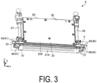
- FIG. 3 is a perspective view illustrating an example of a liquid discharge head according to the embodiment.
- FIG. 4A is an enlarged perspective view of a region IV illustrated in FIG. 3.
- FIG. 4B is a perspective view of the region IV illustrated in FIG. 3 as viewed from a different direction.
- FIG. 5A is an enlarged perspective view of a region V illustrated in FIG. 3.
- FIG. 5B is a perspective view of the region V illustrated in FIG. 3 as viewed from a different direction.
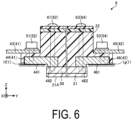
- FIG. 6 is a cross-sectional view illustrating an example of the liquid discharge head according to the embodiment.
- FIG. 7 is a perspective view illustrating an example of a second channel member included in the liquid discharge head according to the embodiment.
- FIG. 8 is a perspective view illustrating an example of a state in which a grounding member is installed at the second channel member illustrated in FIG. 7.
- FIG. 9 is a cross-sectional view illustrating an example of the liquid discharge head according to the embodiment.
- FIG. 10 is a cross-sectional view illustrating another example of the liquid discharge head according to the embodiment.
- FIG. 11 is a perspective view illustrating an example of an electrically conductive member according to the embodiment.
DESCRIPTION OF EMBODIMENTS
-
In the liquid discharge head described above, there is room for further improvement in terms of achieving stable grounding.
-
Therefore, it is expected that a liquid discharge head and a liquid discharge device that can be stably grounded are provided.
-
Embodiments of a liquid discharge head and a liquid discharge device disclosed in the present application will be described below with reference to the accompanying drawings. Note that the present disclosure is not limited to the embodiments described below. Note that the drawings are schematic and that the dimensional relationships between elements, the proportions of the elements, and the like may differ from the actual ones. There may be differences between the drawings in terms of dimensional relationships and proportions.
-
In the following embodiments, expressions such as "constant", "orthogonal", "perpendicular", and "parallel" may be used, but these expressions need not mean exactly "constant", "orthogonal", "perpendicular", and "parallel". In other words, it is assumed that the above expressions allow for deviations in manufacturing accuracy, installation accuracy, or the like.
-
The embodiments can be appropriately combined within a range so as not to contradict each other in terms of processing content. In the following embodiments, the same portions are denoted by the same reference signs, and redundant explanations are omitted.
Embodiment
Configuration of Printer
-
First, with reference to FIG. 1 and FIG. 2, a description will be given of an overview of a printer serving as an example of a liquid discharge device according to an embodiment. FIG. 1 is a front view schematically illustrating an overall front of the printer according to the embodiment. FIG. 2 is a plan view schematically illustrating an overall plane of the printer according to the embodiment. The printer according to the embodiment is, for example, a color inkjet printer.
-
As illustrated in FIG. 1, a printer 1 includes a paper feed roller 2, guide rollers 3, an applicator 4, a head case 5, a plurality of transport rollers 6, a plurality of frames 7, a plurality of liquid discharge heads 8, transport rollers 9, a dryer 10, transport rollers 11, a sensor 12, and a collection roller 13. The transport roller 6 is an example of a transporter.
-
The printer 1 further includes a controller 14. The controller 14 controls each component of the printer 1. The controller 14 controls, for example, operations of the paper feed roller 2, the guide rollers 3, the applicator 4, the head case 5, the plurality of transport rollers 6, the plurality of frames 7, the plurality of liquid discharge heads 8, the transport rollers 9, the dryer 10, the transport rollers 11, the sensor 12, and the collection roller 13.
-
By depositing droplets on a printing sheet P, the printer 1 records images and characters on the printing sheet P. The printing sheet P is an example of a recording medium. The printing sheet P is rolled on the paper feed roller 2 prior to use. The printer 1 transports the printing sheet P from the paper feed roller 2 to the inside of the head case 5 via the guide rollers 3 and the applicator 4.
-
The applicator 4 uniformly applies a coating agent over the printing sheet P. Accordingly, a surface treatment can be performed on the printing sheet P, and the printing quality of the printer 1 can thus be improved.
-
The head case 5 houses the plurality of transport rollers 6, the plurality of frames 7, and the plurality of liquid discharge heads 8. The inside of the head case 5 is formed with a space separated from the outside except for portions connected to the outside such as portions from which the printing sheet P enters and exits the head case 5.
-
The controller 14 controls at least one of controllable factors of the internal space of the head case 5, such as temperature, humidity, and air pressure, as necessary. The transport rollers 6 transport the printing sheet P to the vicinity of the liquid discharge heads 8 inside the head case 5.
-
The frames 7 are rectangular flat plates and are located above and in close proximity to the printing sheet P transported by the transport rollers 6. As illustrated in FIG. 2, the frames 7 are located such that the longitudinal direction is orthogonal to the transport direction of the printing sheet P. The plurality of frames 7 (e.g., four frames) are located at predetermined intervals along the transport direction of the printing sheet P in the head case 5.
-
A liquid, for example, ink, is supplied to the liquid discharge head 8 from a liquid tank (not illustrated). The liquid discharge head 8 discharges the liquid supplied from the liquid tank.
-
The controller 14 controls the liquid discharge heads 8 on the basis of data of an image, characters, or the like to discharge the liquid toward the printing sheet P. The distance between each of the liquid discharge heads 8 and the printing sheet P is, for example, approximately from 0.5 mm to 20 mm.
-
The liquid discharge heads 8 are fixed to the frames 7. The liquid discharge heads 8 are located such that the longitudinal direction is orthogonal to the transport direction of the printing sheet P.
-
In other words, the printer 1 according to the present embodiment is a so-called line printer in which the liquid discharge heads 8 are fixed inside the printer 1. Note that the printer 1 according to the present embodiment is not limited to the line printer and may also be a so-called serial printer.
-
The serial printer is a printer employing a method of alternately performing an operation of recording while moving the liquid discharge heads 8 such that the liquid discharge heads 8 reciprocate in a direction intersecting, for example, substantially orthogonal to the transport direction of the printing sheet P, and an operation of transporting the printing sheet P.
-
As illustrated in FIG. 2, a plurality of liquid discharge heads 8 (e.g., five liquid discharge heads) are fixed to one frame 7. FIG. 2 illustrates an example in which three liquid discharge heads 8 are located on the front side and two liquid discharge heads 8 are located on the rear side, in the transport direction of the printing sheet P. The liquid discharge heads 8 are located such that their centers do not overlap in the transport direction of the printing sheet P.
-
The plurality of liquid discharge heads 8 located in one frame 7 form a head group 8A. Four head groups 8A are located along the transport direction of the printing sheet P. The liquid discharge heads 8 belonging to the same head group 8A are supplied with four colors of ink. As a result, the printer 1 can perform printing with four colors of ink by using the four head groups 8A.
-
The colors of the ink discharged from the respective liquid discharge heads 8 are, for example, magenta (M), yellow (Y), cyan (C), and black (K). The controller 14 can print a color image on the printing sheet P by controlling the respective liquid discharge heads 8 to discharge the plurality of colors of ink onto the printing sheet P.
-
Note that a coating agent may be discharged from the liquid discharge heads 8 onto the printing sheet P to perform a surface treatment on the printing sheet P.
-
The number of the liquid discharge heads 8 included in one of the head groups 8A and the number of the head groups 8A mounted on the printer 1 can be changed as appropriate in accordance with an object to be printed and printing conditions. For example, the number of the liquid discharge heads 8 mounted on the printer 1 may be one when it is desired to print a printable area that can be printed with one liquid discharge head 8.
-
The printing sheet P on which the printing has been performed inside the head case 5 is transported to the outside of the head case 5 by the transport rollers 9 and passes through the inside of the dryer 10. The dryer 10 dries the printing sheet P on which the printing has been performed. The printing sheet P dried by the dryer 10 is transported by the transport rollers 11 and then collected by the collection roller 13.
-
In the printer 1, drying the printing sheet P with the dryer 10 helps prevent adhesion of overlapped portions of the printing sheet P wound up in an overlapped manner and helps prevent undried liquid from rubbing on the collection roller 13.
-
The sensor 12 includes a position sensor, a speed sensor, or a temperature sensor. On the basis of information from the sensor 12, the controller 14 can determine the state of each part of the printer 1 and control each part of the printer 1.
-
In the printer 1 described above, a case where the printing sheet P is used as an object to be printed (i.e., a recording medium) is indicated, but the object to be printed in the printer 1 is not limited to the printing sheet P, and a rolled cloth or the like may be used as the object to be printed.
-
The printer 1 may transport the printing sheet P put on a conveyor belt instead of directly transporting the printing sheet P. By using the conveyor belt, the printer 1 can use a sheet of paper, a cut cloth, wood, a tile, or the like as the object to be printed.
-
The printer 1 may discharge a liquid containing electrically conductive particles from the liquid discharge heads 8 to print a wiring pattern or the like of an electronic device. The printer 1 may discharge a predetermined amount of a liquid chemical agent or a liquid containing the chemical agent from the liquid discharge heads 8 onto a reaction vessel or the like to produce chemicals.
-
The printer 1 may also include a cleaner for cleaning the liquid discharge heads 8. The cleaner cleans the liquid discharge heads 8, for example, by a wiping process or a capping process.
-
The wiping process is, for example, a process of wiping the surface of a portion from which a liquid is discharged, with a flexible wiper, thereby removing the liquid attached to the liquid discharge head 8.
-
The capping process is performed as follows, for example. First, a cap is placed over the surface of the area to which the liquid is to be discharged (this is called capping). This creates a substantially hermetically sealed space between the surface of the area to which the liquid is to be discharged and the cap. Discharge of the liquid is repeated in such a hermetically sealed space. Consequently, a liquid having viscosity higher than that in a normal state, a foreign matter, or the like that has clogged a nozzle 21A (see FIG. 3) can be removed.
Configuration of Liquid Discharge Head
-
A configuration of the liquid discharge head 8 according to the embodiment will be described with reference to FIG. 3. FIG. 3 is a perspective view illustrating an example of the liquid discharge head according to the embodiment.
-
For the sake of clarity, FIG. 3 illustrates a three-dimensional orthogonal coordinate system including the Z-axis in which a vertically upward direction is a positive direction. Such an orthogonal coordinate system may also be presented in other drawings used in the description below. For the sake of convenience, a direction in which the nozzle 21A (see FIG. 3) is located in the liquid discharge head 8, that is, the negative direction side of the Z-axis may be referred to as "under" or "below", and the positive direction side of the Z-axis may be referred to as "on" or "above" in the following description. In FIGs. 3 to 6, the members may be omitted or illustrated in a simplified manner.
-
As illustrated in FIG. 3, the liquid discharge head 8 includes a first channel member 21, a second channel member 22, a pressurizer 23, a first channel 27, a second channel 28, a head cover 29, heat dissipation plates 30, and electrically conductive portions 41, 42.
-
The first channel member 21 is located on a bottom surface side of the liquid discharge head 8, which faces the printing sheet P (see FIG. 1). The first channel member 21 includes the nozzle 21A. The nozzle 21A opens into the bottom surface of the liquid discharge head 8 and discharges the liquid supplied to the inside of the first channel member 21 to the outside.
-
The first channel member 21 has electrical conductivity. Examples of the material of the first channel member 21 include stainless steel.
-
The second channel member 22 is located above the first channel member 21. The second channel member 22 supplies the liquid to the first channel member 21. The second channel member 22 includes a channel 22A connecting to the nozzle 21A. The liquid is supplied from the first channel 27 to the inside of the channel 22A.
-
Examples of the material of the second channel member 22 include a modified polyphenylene ether (PPE) resin such as Zylon (product name) and an epoxy resin such as Epocluster (trade name). The second channel member 22 may contain a carbon material such as carbon black.
-
The pressurizer 23 applies pressure to the first channel member 21. The pressurizer 23 controls the discharge of the liquid from the first channel member 21 in accordance with a control signal output from the controller 14 (see FIG. 1). The pressurizer 23 includes a piezoelectric element that is displaced by energization and a pressure chamber whose internal pressure changes in accordance with the displacement of the piezoelectric element. The pressurizer 23 changes the internal pressure of the pressure chamber and thus changes the pressure applied to the first channel member 21, thereby controlling the discharge of the liquid from the nozzle 21A.
-
The first channel 27 supplies the liquid to the channel 22A of the second channel member 22. The second channel 28 recovers the liquid from the channel 22A of the second channel member 22. When ink is introduced into the liquid discharge head 8 for the first time, the introduction of the ink into the liquid discharge head 8 can be facilitated by removing air, a preservative solution, or the like inside the channel 22A from the second channel 28. In printing, the second channel 28 may be closed or may recover the ink in the channel 22A. The liquid recovered from the second channel 28 is supplied to the first channel 27, for example, through a filter (not illustrated).
-
The head cover 29 has a plate shape and is disposed to cover a space located on the opposite side of the first channel member 21 with the second channel member 22 interposed therebetween.
-
The head cover 29 can be made of an electrically conductive metal material such as aluminum. The head cover 29 may be made of, for example, an electrically conductive or insulating resin material. Thus, heat is appropriately released from the liquid discharge head 8 via the head cover 29. The thermal conductivity of the head cover 29 may be higher than that of the second channel member 22. Accordingly, heat conduction from the head cover 29 to the second channel member 22 is less likely to occur. Therefore, for example, the probability of occurrence of a defect in discharge performance due to a change in the properties of the liquid flowing through the second channel member 22 can be reduced.
-
The head cover 29 may be in contact with the second channel member 22 or may be separated from the second channel member 22. The head cover 29 is located separately from the second channel member 22, and thus heat conduction from the head cover 29 to the second channel member 22 is less likely to occur, and heat conduction to the heat dissipation plates 31, 32 is promoted. Therefore, for example, the probability of occurrence of a defect in discharge performance due to a change in the properties of the liquid flowing through the second channel member 22 can be reduced.
-
The heat dissipation plates 30 are plate-like members located along the YZ plane. The heat dissipation plates 30 are located to face each other in the X axis direction with the head cover 29 interposed therebetween. Note that a heat dissipation plate 30 may be located only at an end portion on the positive side in the X axis direction or the negative side in the X axis direction.
-
The heat dissipation plates 30 can be made of, for example, the same material as the head cover 29. The heat dissipation plates 30 may be made of, for example, a material having higher thermal conductivity than that of the head cover 29.
-
The electrically conductive portions 41, 42 are located at end portions in the length direction (Y axis direction). The electrically conductive portion 41 is located at an end portion on the negative side in the Y axis direction, and the electrically conductive portion 42 is located at an end portion on the positive side in the Y axis direction. The electrically conductive portions 41, 42 include a positioning mechanism for determining the position of the nozzle 21A. The electrically conductive portions 41, 42 are made of an electrically conductive material having higher electrical conductivity than that of the second channel member 22 and are electrically continuous to the first channel member 21. This enables stable grounding.
Configuration of Electrically Conductive Portion
-
The configurations of the electrically conductive portions 41, 42 included in the liquid discharge head 8 according to the embodiment will be further described with reference to FIGs. 3 to 6. FIG. 4A is an enlarged perspective view of a region IV illustrated in FIG. 3. FIG. 4B is a perspective view of the region IV illustrated in FIG. 3 as viewed from a different direction. FIG. 5A is an enlarged perspective view of a region V illustrated in FIG. 3. FIG. 5B is a perspective view of the region V illustrated in FIG. 3 as viewed from a different direction. FIG. 6 is a cross-sectional view illustrating an example of the liquid discharge head according to the embodiment.
-
As illustrated in FIGs. 3 to 4B, the electrically conductive portion 41 serving as a first electrically conductive portion includes a plate member 43 and a grounding member 44. The electrically conductive portion 41 can be made of the same metal material as the first channel member 21. Accordingly, galvanic corrosion, which is also referred to as so-called dissimilar metal corrosion, is less likely to occur, which improves the durability of the liquid discharge head 8.
-
The plate member 43 is located on the positive side of the second channel member 22 in the Z axis direction. The plate member 43 is fixed to the second channel member 22 using first fixing members 51, 52.
-
The plate member 43 includes a protruding portion 431 protruding in the length direction (negative side in the Y axis direction), and the plate member 43 has a substantially L-shape in plan view as viewed from the Z axis direction. When the liquid discharge head 8 is mounted on the liquid discharge device, the plate member 43 functions as a positioning mechanism on one end side in the length direction (negative side in the Y axis direction).
-
The plate member 43 can be fixed to the grounding member 44 of the electrically conductive portion 41 using the first fixing members 51, 52. Accordingly, the plate member 43 is fixed to the grounding member 44 having higher rigidity than the second channel member 22, thereby improving the positioning accuracy by the plate member 43.
-
The grounding member 44 is located on the negative side of the second channel member 22 in the Z axis direction. The grounding member 44 is fixed to the second channel member 22 using the first fixing members 51, 52. The grounding member 44 is fixed to the first channel member 21 and the second channel member 22 using second fixing members 61, 62. The first fixing members 51, 52 and the second fixing members 61, 62 may be, for example, screw members made of metal.
-
As illustrated in FIGs. 3, 5A, and 5B, the electrically conductive portion 42 serving as a second electrically conductive portion may include a plate member 45 and a grounding member 46. The plate member 45 is located on the positive side of the second channel member 22 in the Z axis direction. The plate member 45 is fixed to the second channel member 22 using first fixing members 53 and 54.
-
The plate member 45 protrudes in the length direction (positive side in the Y axis direction) and includes a cutout portion 451 at the center in the width direction (X axis direction). When the liquid discharge head 8 is mounted on the liquid discharge device, the plate member 45 functions as a positioning mechanism on one end side in the length direction (positive side in the Y axis direction). For example, the liquid discharge head 8 is located such that a pillar-shaped or rod-shaped guide member (not illustrated) extending in the height direction (Z axis direction) is in contact with the cutout portion 451. Thus, the liquid discharge device including the nozzle 21A at a predetermined position can be obtained.
-
The plate member 45 can be fixed to the grounding member 46 of the electrically conductive portion 42 using the first fixing members 53, 54. Accordingly, the plate member 45 is fixed to the grounding member 46 having higher rigidity than the second channel member 22, thereby improving the positioning accuracy by the plate member 45.
-
The grounding member 46 is located on the negative side of the second channel member 22 in the Z axis direction. The grounding member 46 is fixed to the second channel member 22 using the first fixing members 53, 54. The grounding member 46 is fixed to the first channel member 21 and the second channel member 22 using second fixing members 63, 64. The first fixing members 53, 54 and the second fixing members 63, 64 may be, for example, screw members made of metal.
-
As illustrated in FIG. 6, the grounding member 44 may include a first portion 441 and a second portion 442. The grounding member 46 may include a first portion 461 and a second portion 462. When the liquid discharge head 8 is mounted on the mounting surfaces 1f, 1g of the printer 1 serving as an example of the liquid discharge device, the first portions 441, 461 may be contact surfaces that are in contact with mounting surfaces 1f, 1g, respectively. The liquid discharge head 8 mounted on the mounting surfaces 1f, 1g can be stably grounded by appropriately grounding the first portions 441, 461. Since the liquid discharge head 8 includes, in this way, the electrically conductive portions 41, 42 that are electrically continuous to the first channel member 21 and that have higher electrical conductivity than the second channel member 22, the stable grounding is enabled, for example, even when electric noise is generated.
-
The second portions 442, 462 are contact surfaces that are in contact with the first channel member 21. The second fixing members 61 to 64 for fixing the first channel member 21 and the second channel member 22 penetrate the second portions 442, 462. The second fixing members 61, 62 penetrate the second portion 442. The second fixing members 63, 64 penetrate the second portion 462. The second fixing members 61 to 64 penetrate the second portions 442, 462 of the grounding members 44, 46 in this way, and thus the grounding members 44, 46 and the first channel member 21 can be stably brought into contact with each other, which can reduce the grounding resistance of the liquid discharge head 8.
-
The second fixing members 61, 62 penetrate the second portion 442 of the grounding member 44 and the second fixing members 63, 64 penetrate the second portion 462 of the grounding member 46. Thus, deformation of the grounding members 44, 46 and inclination of the grounding members 44, 46 due to a moment force generated by fastening the second fixing members 61 to 64 are less likely to occur compared to a case where the second fixing members 61, 62 penetrate portions different from the second portions 442, 462.
-
As illustrated in FIGs. 3 to 5B, the grounding member 44 of the electrically conductive portion 41 and the first channel member 21 may be in contact with each other throughout the width direction (X axis direction). The grounding member 46 of the electrically conductive portion 42 and the first channel member 21 may be in contact with each other throughout the width direction (X axis direction). This can increase the contact area between the electrically conductive portions 41, 42 and the first channel member 21 and stably ground the first channel member 21.
-
The electrically conductive portions 41, 42 may be in contact with the second channel member 22 throughout the width direction (X axis direction). This improves the positional stability of the electrically conductive portions 41, 42 with respect to the second channel member 22.
-
Note that, as illustrated in FIG. 6, in the grounding member 44, the area of the first portion 441 may be larger than the area of the second portion 442. Similarly, in the grounding member 46, the area of the first portion 461 may be larger than the area of the second portion 462. The area of the second portion 442 may be larger than the area of the first portion 441, and the area of the second portion 462 may be larger than the area of the first portion 461. When the area of the second portion 442 is larger than the area of the first portion 441, for example, the contact area between the first channel member 21 and the grounding member 44 can be increased. When the area of the second portion 462 is larger than the area of the first portion 461, for example, the contact area between the first channel member 21 and the grounding member 46 can be increased. Thus, stable grounding can be achieved.
-
As illustrated in FIG. 6, the grounding member 44 may include a step between the first portion 441 and the second portion 442, or the first portion 441 and the second portion 442 may be flush with each other. Similarly, the grounding member 46 may include a step between the first portion 461 and the second portion 462, or the first portion 461 and the second portion 462 may be flush with each other.
-
FIG. 7 is a perspective view illustrating an example of the second channel member included in the liquid discharge head according to the embodiment. FIG. 8 is a perspective view illustrating an example of a state in which the grounding member is installed at the second channel member illustrated in FIG. 7. FIG. 9 is a cross-sectional view illustrating an example of the liquid discharge head according to the embodiment.
-
As illustrated in FIG. 7, the second channel member 22 includes a bottom surface 221 and a peripheral wall 222. The bottom surface 221 is recessed toward the positive side in the Z axis direction from an end surface on the negative side of the second channel member 22 in the Z axis direction, which is located to face the first channel member 21. The peripheral wall 222 is located to surround the bottom surface 221. The grounding member 44 is mounted so as to be embedded in the recessed portion of the second channel member 22 including the bottom surface 221 and the peripheral wall 222. Embedding the grounding member 44 in the recessed portion of the second channel member 22 in this way improves the rigidity of the second channel member 22 and also improves the positional stability of the grounding member 44 in the liquid discharge head 8.
-
The second channel member 22 may include a protruding pin 223. The protruding pin 223 protrudes from the bottom surface 221 toward the negative side in the Z axis direction. As illustrated in FIG. 8, the protruding pin 223 is inserted into a through hole 443 extending through the grounding member 44 in the thickness direction (Z axis direction). As illustrated in FIG. 9, a distal end of the protruding pin 223 is located inside the first channel member 21. Providing such a protruding pin 223 in this way improves the positional stability of the first channel member 21 and the second channel member 22. The material cost of the grounding member 44 can be reduced compared to a case where a protruding pin protruding from the grounding member 44 is provided, which can reduce the manufacturing cost of the liquid discharge head 8.
-
Note that although the shape of the second channel member 22 located on the grounding member 44 side has been described in FIGs. 7 to 9, the second channel member 22 located on the grounding member 46 side can also have the same and/or a similar shape.
-
Referring back to FIG. 6, the liquid discharge head 8 may include a connecting portion 50. The connecting portion 50 connects the electrically conductive portions 41, 42 located at both end portions in the length direction (Y axis direction) to each other. The connecting portion 50 has electrical conductivity. The connecting portion 50 can be made of the same metal material as the first channel member 21. The connecting portion 50 may be a part of the first channel member 21.
-
The connecting portion 50 may be located between the nozzle 21A and the electrically conductive portions 41, 42. The connecting portion 50 may be, for example, a lid-like member configured to close the liquid channel located inside the first channel member 21. The connecting portion 50 may include, for example, an accommodation portion accommodating the pressurizer 23 (see FIG. 3) therein. The connecting portion 50 may be integrated with the first channel member 21 or may be separated from the first channel member 21. Since the liquid discharge head 8 includes the connecting portion 50, the first channel member 21 can be immediately made electrically continuous to the liquid discharge device, and stable grounding can be achieved.
-
FIG. 10 is a cross-sectional view illustrating another example of the liquid discharge head according to the embodiment. As illustrated in FIG. 10, the liquid discharge head 8 may include an electrically conductive member 40. The electrically conductive member 40 can be made of the same metal material as the first channel member 21.
-
FIG. 11 is a perspective view illustrating an example of the electrically conductive member according to the embodiment. As illustrated in FIGs. 10 and 11, the electrically conductive member 40 may include grounding portions 44A, 46A located at both end portions in the length direction (Y axis direction) and a connecting portion 50A located between the grounding portions 44A, 46A.
-
The grounding portions 44A, 46A include first portions 441, 461 placed at the mounting surfaces 1f, 1g of the printer 1, respectively. The grounding portions 44A, 46A correspond to the grounding members 44, 46 illustrated in FIG. 6, respectively. The connecting portion 50A corresponds to the connecting portion 50 illustrated in FIG. 6. The electrically conductive member 40 integrally includes the grounding portions 44A, 46A and the connecting portion 50A. According to the liquid discharge head 8 including such an electrically conductive member 40, the positions of the grounding portions 44A, 46A are less likely to be shifted, for example, even when the liquid discharge head 8 receives an external force. This can achieve the stable grounding of the liquid discharge head 8.
Other Embodiments
-
In the above-described embodiment, a case in which the grounding members 44, 46 each are fixed at four points using the first fixing members and the second fixing members has been described as an example. However, the grounding members 44, 46 each may be fixed at two or more points. For example, when the grounding members 44, 46 each are fixed at two points, one point may function to determine the position of each of the grounding members 44, 46, and the other point may function to stop the rotation of each of the grounding members 44, 46. Accordingly, for example, even when the liquid discharge head 8 receives an external force, the positions of the grounding members 44, 46 are less likely to be shifted.
-
In the above-described embodiment, an aspect has been described in which the ink is supplied from the outside to the reservoir constituted by the second channel member 22 at the time of printing, and an aspect has been described in which the ink is supplied from the outside to the reservoir and also the ink is collected from the reservoir to the outside at the time of printing. In the latter aspect, the ink may be supplied from the reservoir to the first channel member 21, and also the ink may be recovered from the first channel member 21 to the reservoir. In the first channel member 21, the ink may be supplied to and recovered from the channel facing the nozzle 21A so as to be less likely to stay in the nozzle 21A and the periphery thereof. In such an aspect, as a whole, the ink is supplied to the liquid discharge head 8 from the outside, the ink is partly discharged, and the ink not discharged is collected to the outside. The ink collected to the outside may be supplied to the liquid discharge head 8 again. That is, the ink may be circulated. The controller 14 may control the supply and recovery of the ink to and from the liquid discharge head 8 or the circulation of the ink.
-
As described above, the liquid discharge head 8 according to the embodiment includes the first channel member 21, the second channel member 22, and the electrically conductive portions 41, 42. The first channel member 21 has electrical conductivity and includes the nozzle 21A configured to discharge the liquid. The second channel member 22 supplies the liquid to the first channel member 21. The electrically conductive portions 41, 42 include a positioning mechanism configured to determine the position of the nozzle 21A. The electrically conductive portions 41, 42 are electrically continuous to the first channel member 21 and have higher electrical conductivity than the second channel member 22. As a result, according to the liquid discharge head 8 of the embodiment, stable grounding can be achieved.
-
Further effects and variations can be readily derived by those skilled in the art. Thus, a wide variety of aspects of the present invention are not limited to the specific details and representative embodiments represented and described above. Accordingly, various changes can be made without departing from the spirit or scope of the general inventive concepts defined by the appended claims and their equivalents.
REFERENCE SIGNS
-
- 1 Printer
- 8 Liquid discharge head
- 14 Controller
- 21 First channel member
- 21A Nozzle
- 22 Second channel member
- 23 Pressurizer
- 29 Head cover
- 30 Heat dissipation plate
- 40 Electrically conductive member
- 41, 42 Electrically conductive portion
- 43, 45 Plate member
- 44, 46 Grounding member