EP4582227A1 - Robot system, automated pressing system, program, and pressing jig - Google Patents
Robot system, automated pressing system, program, and pressing jig Download PDFInfo
- Publication number
- EP4582227A1 EP4582227A1 EP23860402.9A EP23860402A EP4582227A1 EP 4582227 A1 EP4582227 A1 EP 4582227A1 EP 23860402 A EP23860402 A EP 23860402A EP 4582227 A1 EP4582227 A1 EP 4582227A1
- Authority
- EP
- European Patent Office
- Prior art keywords
- plate jig
- pressing
- workpiece
- jig
- target object
- Prior art date
- Legal status (The legal status is an assumption and is not a legal conclusion. Google has not performed a legal analysis and makes no representation as to the accuracy of the status listed.)
- Pending
Links
Images







Classifications
-
- B—PERFORMING OPERATIONS; TRANSPORTING
- B21—MECHANICAL METAL-WORKING WITHOUT ESSENTIALLY REMOVING MATERIAL; PUNCHING METAL
- B21D—WORKING OR PROCESSING OF SHEET METAL OR METAL TUBES, RODS OR PROFILES WITHOUT ESSENTIALLY REMOVING MATERIAL; PUNCHING METAL
- B21D43/00—Feeding, positioning or storing devices combined with, or arranged in, or specially adapted for use in connection with, apparatus for working or processing sheet metal, metal tubes or metal profiles; Associations therewith of cutting devices
-
- B—PERFORMING OPERATIONS; TRANSPORTING
- B23—MACHINE TOOLS; METAL-WORKING NOT OTHERWISE PROVIDED FOR
- B23P—METAL-WORKING NOT OTHERWISE PROVIDED FOR; COMBINED OPERATIONS; UNIVERSAL MACHINE TOOLS
- B23P21/00—Machines for assembling a multiplicity of different parts to compose units, with or without preceding or subsequent working of such parts, e.g. with program control
- B23P21/008—Machines for assembling a multiplicity of different parts to compose units, with or without preceding or subsequent working of such parts, e.g. with program control the assembling machines or tools moving synchronously with the units while these are being assembled
-
- B—PERFORMING OPERATIONS; TRANSPORTING
- B25—HAND TOOLS; PORTABLE POWER-DRIVEN TOOLS; MANIPULATORS
- B25J—MANIPULATORS; CHAMBERS PROVIDED WITH MANIPULATION DEVICES
- B25J13/00—Controls for manipulators
-
- B—PERFORMING OPERATIONS; TRANSPORTING
- B25—HAND TOOLS; PORTABLE POWER-DRIVEN TOOLS; MANIPULATORS
- B25J—MANIPULATORS; CHAMBERS PROVIDED WITH MANIPULATION DEVICES
- B25J13/00—Controls for manipulators
- B25J13/06—Control stands, e.g. consoles, switchboards
-
- B—PERFORMING OPERATIONS; TRANSPORTING
- B25—HAND TOOLS; PORTABLE POWER-DRIVEN TOOLS; MANIPULATORS
- B25J—MANIPULATORS; CHAMBERS PROVIDED WITH MANIPULATION DEVICES
- B25J15/00—Gripping heads and other end effectors
-
- B—PERFORMING OPERATIONS; TRANSPORTING
- B25—HAND TOOLS; PORTABLE POWER-DRIVEN TOOLS; MANIPULATORS
- B25J—MANIPULATORS; CHAMBERS PROVIDED WITH MANIPULATION DEVICES
- B25J9/00—Program-controlled manipulators
- B25J9/16—Program controls
- B25J9/1612—Program controls characterised by the hand, wrist, grip control
-
- B—PERFORMING OPERATIONS; TRANSPORTING
- B25—HAND TOOLS; PORTABLE POWER-DRIVEN TOOLS; MANIPULATORS
- B25J—MANIPULATORS; CHAMBERS PROVIDED WITH MANIPULATION DEVICES
- B25J9/00—Program-controlled manipulators
- B25J9/16—Program controls
- B25J9/1679—Program controls characterised by the tasks executed
- B25J9/1687—Assembly, peg and hole, palletising, straight line, weaving pattern movement
-
- B—PERFORMING OPERATIONS; TRANSPORTING
- B25—HAND TOOLS; PORTABLE POWER-DRIVEN TOOLS; MANIPULATORS
- B25J—MANIPULATORS; CHAMBERS PROVIDED WITH MANIPULATION DEVICES
- B25J9/00—Program-controlled manipulators
- B25J9/16—Program controls
- B25J9/1694—Program controls characterised by use of sensors other than normal servo-feedback from position, speed or acceleration sensors, perception control, multi-sensor controlled systems, sensor fusion
- B25J9/1697—Vision controlled systems
-
- B—PERFORMING OPERATIONS; TRANSPORTING
- B29—WORKING OF PLASTICS; WORKING OF SUBSTANCES IN A PLASTIC STATE IN GENERAL
- B29C—SHAPING OR JOINING OF PLASTICS; SHAPING OF MATERIAL IN A PLASTIC STATE, NOT OTHERWISE PROVIDED FOR; AFTER-TREATMENT OF THE SHAPED PRODUCTS, e.g. REPAIRING
- B29C43/00—Compression moulding, i.e. applying external pressure to flow the moulding material; Apparatus therefor
- B29C43/32—Component parts, details or accessories; Auxiliary operations
- B29C43/34—Feeding the material to the mould or the compression means
-
- B—PERFORMING OPERATIONS; TRANSPORTING
- B30—PRESSES
- B30B—PRESSES IN GENERAL
- B30B15/00—Details of, or accessories for, presses; Auxiliary measures in connection with pressing
- B30B15/30—Feeding material to presses
-
- G—PHYSICS
- G05—CONTROLLING; REGULATING
- G05B—CONTROL OR REGULATING SYSTEMS IN GENERAL; FUNCTIONAL ELEMENTS OF SUCH SYSTEMS; MONITORING OR TESTING ARRANGEMENTS FOR SUCH SYSTEMS OR ELEMENTS
- G05B19/00—Program-control systems
- G05B19/02—Program-control systems electric
- G05B19/418—Total factory control, i.e. centrally controlling a plurality of machines, e.g. direct or distributed numerical control [DNC], flexible manufacturing systems [FMS], integrated manufacturing systems [IMS] or computer integrated manufacturing [CIM]
- G05B19/41805—Total factory control, i.e. centrally controlling a plurality of machines, e.g. direct or distributed numerical control [DNC], flexible manufacturing systems [FMS], integrated manufacturing systems [IMS] or computer integrated manufacturing [CIM] characterised by assembly
-
- G—PHYSICS
- G05—CONTROLLING; REGULATING
- G05B—CONTROL OR REGULATING SYSTEMS IN GENERAL; FUNCTIONAL ELEMENTS OF SUCH SYSTEMS; MONITORING OR TESTING ARRANGEMENTS FOR SUCH SYSTEMS OR ELEMENTS
- G05B2219/00—Program-control systems
- G05B2219/20—Pc systems
- G05B2219/26—Pc applications
- G05B2219/2622—Press
-
- G—PHYSICS
- G05—CONTROLLING; REGULATING
- G05B—CONTROL OR REGULATING SYSTEMS IN GENERAL; FUNCTIONAL ELEMENTS OF SUCH SYSTEMS; MONITORING OR TESTING ARRANGEMENTS FOR SUCH SYSTEMS OR ELEMENTS
- G05B2219/00—Program-control systems
- G05B2219/30—Nc systems
- G05B2219/35—Nc in input of data, input till input file format
- G05B2219/35043—Tool, fixture design
-
- G—PHYSICS
- G05—CONTROLLING; REGULATING
- G05B—CONTROL OR REGULATING SYSTEMS IN GENERAL; FUNCTIONAL ELEMENTS OF SUCH SYSTEMS; MONITORING OR TESTING ARRANGEMENTS FOR SUCH SYSTEMS OR ELEMENTS
- G05B2219/00—Program-control systems
- G05B2219/30—Nc systems
- G05B2219/39—Robotics, robotics to robotics hand
- G05B2219/39468—Changeable hand, tool, code carrier, detector
-
- G—PHYSICS
- G05—CONTROLLING; REGULATING
- G05B—CONTROL OR REGULATING SYSTEMS IN GENERAL; FUNCTIONAL ELEMENTS OF SUCH SYSTEMS; MONITORING OR TESTING ARRANGEMENTS FOR SUCH SYSTEMS OR ELEMENTS
- G05B2219/00—Program-control systems
- G05B2219/30—Nc systems
- G05B2219/40—Robotics, robotics mapping to robotics vision
- G05B2219/40059—Mount, couple and demount, decouple exchangeable mechanical modules
-
- G—PHYSICS
- G05—CONTROLLING; REGULATING
- G05B—CONTROL OR REGULATING SYSTEMS IN GENERAL; FUNCTIONAL ELEMENTS OF SUCH SYSTEMS; MONITORING OR TESTING ARRANGEMENTS FOR SUCH SYSTEMS OR ELEMENTS
- G05B2219/00—Program-control systems
- G05B2219/30—Nc systems
- G05B2219/45—Nc applications
- G05B2219/45142—Press-line
-
- G—PHYSICS
- G05—CONTROLLING; REGULATING
- G05B—CONTROL OR REGULATING SYSTEMS IN GENERAL; FUNCTIONAL ELEMENTS OF SUCH SYSTEMS; MONITORING OR TESTING ARRANGEMENTS FOR SUCH SYSTEMS OR ELEMENTS
- G05B2219/00—Program-control systems
- G05B2219/30—Nc systems
- G05B2219/50—Machine tool, machine tool null till machine tool work handling
- G05B2219/50362—Load unload with robot
Definitions
- the present disclosure relates to a robot system, a pressing automation system, a program, and a pressing-purpose jig .
- Patent Document 1 Japanese Patent No. 6983437
- a robot system including: an end effector configured to hold a workpiece; an operation device connected to the end effector and configured to operate the end effector; and a control device configured to control an operation of the operation device.
- the control device controls: a step of assembling the workpiece in a form in which a pressing-target object is sandwiched by arranging the pressing-target object on a first plate jig arranged at a set position and thereafter placing a second plate jig on the first plate jig through operating the end effector; and a step of conveying the workpiece to a press position at which the pressing-target object is pressed by holding the pressing-target object, the first plate jig, and the second plate jig altogether as the workpiece with the end effector.
- the control device controls a step of conveying the workpiece to a disassembly position with the end effector by holding the workpiece pressed at the press position, and a step of separating the second plate jig from the first plate jig by operating the end effector at the disassembly position.
- the robot system can smoothly disassemble a pressed workpiece at the disassembly position, and can further promote the reduction of a burden on the user and the improvement of work efficiency.
- the press position includes a first position at which the pressing-target object is pressed while being heated, and in the step of conveying the workpiece, the control device causes the workpiece to be conveyed to the first position and, after the workpiece is being pressed, causes the workpiece to be conveyed to the disassembly position.
- the robot system can press a pressing-target object (polymer) while heating the pressing-target object at the first position, and then immediately return the workpiece to the disassembly position to obtain a press-formed product.
- the press position includes a first position at which the pressing-target object is pressed while being heated and a second position at which the pressing-target object is pressed while being cooled, and in the step of conveying the workpiece, the control device causes the workpiece to be conveyed to the first position first, and after the workpiece is pressed at the first position, causes the workpiece to be conveyed from the first position to the second position.
- the robot system can press a pressing-target object (polymer) while heating a pressing-target object at the first position and then press the pressing-target object while cooling the pressing-target object at the second position.
- the robot system can accurately create a press-formed product in accordance with a target temperature.
- the control device causes the second plate jig to be moved in parallel to a surface direction of the first plate jig so as to face the first plate jig.
- the robot system can smoothly assemble the first plate jig and the second plate jig, suppressing a displacement between the first plate jig and the second plate jig.
- One of the first plate jig and the second plate jig has a frame body, and the other of the first plate jig and the second plate jig has a guide surface guided by the frame body, and in the step of assembling the workpiece, the control device causes the guide surface to be into contact with the frame body when causing the second plate jig to be moved with respect to the first plate jig.
- the robot system can guide and position the relative positions of the first plate jig and the second plate jig by the frame bodies and the guide surface.
- the press position has a concave arrangement space that matches a shape of a distal end of the first plate jig in an entering direction in which the workpiece enters the press position, and in a step of conveying the workpiece to the press position, the control device positions the workpiece by causing the workpiece to be moved in a horizontal direction and bringing the workpiece into contact with a guide wall constituting the concave arrangement space.
- the robot system can guide the workpiece by the guide wall and accurately position the workpiece at the press position.
- the control device causes the pressing-target object to be placed on the first plate jig by causing a cylindrical body to be placed on the first plate jig and subsequently causing the pressing-target object to be placed inside the cylindrical body, and after the cylindrical body is taken out, the control device causes the second plate jig to be arranged on the first plate jig.
- the robot system can favorably prevent the pressing-target object from scattering out of the first plate jig in the step of assembling the workpiece.
- the end effector includes a pair of gripping bodies configured to be moved close to and away from each other under an operation command of the control device, and the control device switches a jig having a grip configured to be gripped by the pair of gripping bodies to another jig having a grip in an operation of arranging the pressing-target object on the first plate jig and an operation of overlaying the second plate jig on the first plate jig.
- the robot system can assemble the workpiece easily and in a short time by switching the jigs between an operation of arranging a pressing-target object on the first plate jig and an operation of overlaying the second plate jig on the first plate jig.
- the plurality of jigs include a supply cup that accommodates the pressing-target object, and a fork jig having a plurality of forks configured to enter under the first plate jig or the second plate jig and lift the first plate jig or the second plate jig.
- the robot system can easily perform an operation of arranging the pressing-target object on the first plate jig and an operation of holding the first plate jig and the second plate jig.
- the plurality of jigs include a temperature detector configured to detect a temperature of the workpiece, and the control device causes the temperature detector to be gripped by the pair of gripping bodies and inserted into the workpiece arranged at the press position.
- the robot system can measure a temperature of the pressing-target object by the temperature detector at the time of pressing a workpiece, and can perform pressing at an appropriate temperature.
- a pressing automation system includes a robot including an end effector configured to hold a workpiece and an operation device connected to the end effector and configured to operate the end effector, a press apparatus configured to press a pressing-target object accommodated in the workpiece conveyed by the robot, and a control device configured to control the robot and the press apparatus.
- the control device controls: a step of assembling the workpiece in a form in which a pressing-target object is sandwiched by arranging the pressing-target object on a first plate jig arranged at a set position and thereafter placing a second plate jig on the first plate jig through operating the end effector; a step of conveying the workpiece from the set position to the press apparatus by holding the pressing-target object, the first plate jig, and the second plate jig altogether as the workpiece with the end effector; and a step of pressing the pressing-target object by pressing the first plate jig and the second plate jig by the press apparatus.
- a program configured to cause a computer to function as: a robot commander configured to output to a robot system a command to assemble a workpiece in a form in which a pressing-target object is sandwiched by arranging the pressing-target object on a first plate jig arranged at a set position and thereafter placing a second plate jig on the first plate jig through operating an end effector at a set position at which the workpiece is set, and convey the workpiece from the set position to a press apparatus by holding the pressing-target object, the first plate jig, and the second plate jig altogether as the workpiece with the end effector; a press commander configured to output to the press apparatus a command to press the pressing-target object; and an analysis commander configured to output to an analysis apparatus a command to analyze the pressed pressing-target object.
- a pressing-purpose jig that is conveyed to a press apparatus while holding a pressing-target object and is pressed by the press apparatus, the pressing-purpose jig including a first plate jig on which the pressing-target object is arranged at a set position, and a second plate jig that forms a workpiece in a form in which the pressing-target object is sandwiched between the first plate jig and the second plate jig by being placed on the first plate jig on which the pressing-target object is arranged.
- the pressing-purpose jig in a form in which the pressing-target object is sandwiched between the first plate jig and the second plate jig is configured to be conveyed to the press apparatus, and the pressing-purpose jig is configured to press the pressing-target object when the press apparatus presses the first plate jig and the second plate jig the pressing-purpose jig is arranged at the press apparatus.
- the same components are denoted by the same reference numerals, and a duplicate description thereof may be omitted.
- the X-axis direction, the Y-axis direction, and the Z-axis direction used in the following description are axial directions that intersect perpendicularly to each other.
- the X-axis direction and the Y-axis direction are horizontal directions, and the Z-axis direction is a vertical direction.
- a sample evaluation system 1 In order to evaluate a polymer (resin) as a sample, a sample evaluation system 1 according to an embodiment includes a pressing automation system 2 that conveys a polymer to a plurality of work places and performs work such as pressing, and an analysis apparatus 3 that evaluates a produced press-formed product, as illustrated in FIG. 1 .
- the sample evaluation system 1 also includes a control apparatus (control device) 4 that controls each of the apparatuses of the pressing automation system 2 and the analysis apparatus 3.
- the pressing automation system 2 includes, for example, a workbench 10, a robot 20, a heat press apparatus 80, and a cold press apparatus 90.
- the robot 20 assembles a workpiece containing a polymer (see also FIG. 8(B) ) on a workbench 10.
- the robot 20 sequentially conveys workpieces to two types of press apparatus (the heat press apparatus 80 and the cold press apparatus 90), and each press apparatus presses the polymer to produce a press-formed product.
- the pressing automation system 2 is not limited to including two types of press apparatus (the heat press apparatus 80 and the cold press apparatus 90), and may include one type of press apparatus or three or more types of apparatuses.
- the pressing automation system 2 may be applied to a press apparatus that does not heat or cool a polymer, or may be configured to press a polymer by adjusting a temperature to a plurality of temperatures in one press apparatus.
- the control apparatus 4 includes one or more processors 4a, a memory 4b, an input/output interfaces 4c, and a communication interface 4d, and is configured as a computer that controls the entire sample evaluation system 1.
- the one or more processors 4a are one or a combination of a plurality of central processing units (CPUs), graphics processing units (GPUs), application specific integrated circuits (ASICs), field-programmable gate arrays (FPGAs), circuits formed of a plurality of discrete semiconductors, and the like.
- the memory 4b includes a nonvolatile memory and a volatile memory (for example, a compact disc, a digital versatile disc (DVD), hard disk, flash memory, and the like), and constitutes a storage unit of the control apparatus 4.
- the input/output interface 4c is connected to an input/output apparatus 5, which is an operator interface that can be operated and checked by an operator of the sample evaluation system 1.
- an input/output apparatus 5 for example, a monitor, a mouse, a keyboard, a touch panel (including a tablet terminal, a smartphone, and the like), a speaker, a microphone, and the like can be appropriately adopted.
- the communication interface 4d performs information communication between each of the robot 20, the heat press apparatus 80, the cold press apparatus 90, and the analysis apparatus 3, and the control apparatus 4 via a communication network 6 capable of wired communication or wireless communication.
- the communication network 6 may be any one of a wide area network (WAN), a local area network (LAN), a personal area network (PAN), and the like, or a combination thereof.
- WANs include the Internet
- LANs include IEEE 802.11 and Ethernet (registered trademark)
- PANs include Bluetooth (registered trademark) and near field communication (NFC).
- the robot 20 is provided with a robot controller 29 that communicates information with the control apparatus 4 and operates the robot 20.
- the heat press apparatus 80 is provided with a heat press controller 89 that communicates information with the control apparatus 4 and operates the heat press apparatus 80.
- the cold press apparatus 90 is provided with a cold press controller 99 that communicates information with the control apparatus 4 and operates the cold press apparatus 90.
- the analysis apparatus 3 is provided with an analysis-purpose controller 3c that communicates information with the control apparatus 4 and operates the analysis apparatus 3.
- the memory 4b of the control apparatus 4 stores a program 100 for controlling the sample evaluation system 1.
- the program 100 is read and executed by the processor 4a, thereby forming a plurality of functional units for controlling the entire sample evaluation system 1 in the control apparatus 4.
- the respective functional units formed under the execution of the program 100 outputs control commands to the pressing automation system 2 (the robot 20, the heat press apparatus 80, and the cold press apparatus 90) and the analysis apparatus 3 at appropriate timings.
- the program 100 functions as bridge software that achieves the creation of press-formed products by the pressing automation system 2 in conjunction with the analysis of the press-formed products by the analysis apparatus 3.
- FIG. 2 illustrates one computer as the control apparatus 4 of the sample evaluation system 1
- software may be installed in a plurality of computers, and the plurality of computers may execute the same or different partial processing of the software.
- the distributed computing may be adopted in which the computers communicate with each other to execute the processing.
- the control apparatus 4 can be configured by a computer for a robot operating system (ROS) connected to each apparatus and a plurality of control computers connected to the computer of the ROS.
- the control apparatus 4 of the sample evaluation system 1 may be configured to process information transmitted from a terminal device with one or more computers provided on the cloud and transmit the processing result to the terminal device.
- ROS robot operating system
- the pressing automation system 2 includes a workbench 10, the heat press apparatus 80, and the cold press apparatus 90, which are arranged around the robot 20.
- the workbench 10, the heat press apparatus 80, and the cold press apparatus 90 are installed so as to form an L shape in a plan view (see also FIG. 1 ).
- the workbench 10 is formed in a rectangular shape extending long along the Y-axis direction at a position away from the robot 20 in the X-axis direction.
- the heat press apparatus 80 and the cold press apparatus 90 are installed at positions away from the robot 20 in the Y-axis direction so as to be arranged along the X-axis direction.
- the arrangement of the workbench 10 and the apparatuses of the pressing automation system 2 is not limited to an L-shape, and may be set at an operator's discretion.
- the workbench 10 forms a work place where the robot 20 assembles and disassembles a workpiece containing a polymer in the pressing automation system 2.
- the workbench 10 includes a base 11, a work-purpose small table 12 installed on the base 11, and a conveying-purpose small table 13 installed on the base 11 so as to be aligned with the work-purpose small table 12 in the Y-axis direction.
- the workbench 10 may be a single table (the base 11 in which the work-purpose small table 12 and the conveying-purpose small table 13 are seamlessly connected in series).
- the base 11 includes a top plate having a rectangular, flat shape in a plan view and a plurality of leg portions supporting the top plate.
- the base 11 is installed in such a manner that the long side of the top plate is along the Y-axis direction.
- a weighing device 14, a removal apparatus 15, and the like are installed, in addition to the work-purpose small table 12 and the conveying-purpose small table 13.
- the work-purpose small table 12 is a table for assembling and disassembling a workpiece containing a polymer.
- the pressing automation system 2 includes a plurality of types of jigs (targets for gripping) 19 for assembling and disassembling a workpiece and are provided on the upper surface of the work-purpose small table 12.
- the plurality of types of jigs 19 will be described in detail later.
- the conveying-purpose small table 13 forms a place where a press-formed product that is produced in the pressing automation system 2 is separated from the jig 19 (a lower plate jig 41) and is kept on standby until the press-formed product is conveyed to the analysis apparatus 3.
- the work surface (upper surface) of the work-purpose small table 12 and the work surface (upper surface) of the conveying-purpose small table 13 are set at a height at which an end effector 25 of the robot 20 can reach.
- the base 11, the work-purpose small table 12, and the conveying-purpose small table 13 may include an adjuster (not illustrated) capable of adjusting the height and parallelism of each upper surface (for example, a level adjuster).
- the weighing device 14 is installed at a position adjacent to the work-purpose small table 12, and weighs a polymer as a pressing-target object.
- the weighing device 14 includes a box-shaped case, and a measurer for measuring a weight of a polymer is provided on the bottom surface of the case.
- the measurer is connected to the control apparatus 4 via the communication network 6, and automatically transmits measurement information (a weight of a polymer) to the control apparatus 4.
- the surface of the case of the weighing device 14 on the side close to the robot 20 is open so that the end effector 25 of the robot 20 can enter the case.
- the robot 20 tilts a container of a granulated polymer, with a supply cup 61 (see FIG. 6 ) being placed on the measurer.
- the supply cup 61 is one of the jigs 19 and will be described later.
- the control apparatus 4 supplies an appropriate amount of polymer to the supply cup 61 by instructing an operation of the robot 20 while monitoring the measurement information of the measurer.
- the removal apparatus 15 is installed at a position adjacent to the conveying-purpose small table 13, and when a press-formed product is adhered to the jig 19, the removal apparatus 15 peels the press-formed product from the jig 19 and takes out the press-formed product.
- a conventional die cutting device, ejector device, or the like can be applied as the removal apparatus 15.
- the plurality of joints 24 are provided between the arms 23 adjacent to each other, and move the arm 23 on the distal end side in relation to the arm 23 on the base 22 side.
- the robot 20 includes a joint motor in each of the base 22 and the joints 24 (or the arms 23).
- the robot 20 includes a plurality of motor drivers that supply electric power to the joint motors under the control of the robot controller 29, and operates the joints 24 independently.
- the end effector 25 of the robot 20 is attached to the distal end of a series of the plurality of arms 23 (the wrist 231).
- the end effector 25 employs a clamp mechanism that grips the jig 19, which is a gripping-target object, with a set (pair) of gripping bodies 27.
- the end effector 25 includes a rectangular parallelepiped housing 26 fixed to the wrist 231, and the pair of gripping bodies 27 is arranged on a distal end surface (tip surface) of the housing 26.
- a gripping body operation device 26a that operates the pair of gripping bodies 27 is provided in the housing 26.
- a portion located inside the frame bodies 43 is formed in a flat shape.
- a polymer is placed on the placement region in this inside portion.
- a pair of stoppers 42d for restricting a movement of the plate body 42 in the distal direction are attached to the base end slide 42c of the plate body 42.
- the plate body 42 may have a shape in which a part thereof is cut out in order to reduce the weight of the entire lower plate jig 41.
- the intermediate plate jig 46 of the pressing-purpose jigs 40 is first arranged on the plate body 42 of the lower plate jig 41, thereby defining a polymer placement region.
- the intermediate plate jig 46 includes a plate body 47 having a plate shape thinner than the plate body 42 of the lower plate jig 41, and a grip 48 connected to the plate body 47 via a connection portion 49.
- a circular hole 47h for defining a placement region is formed in the plate body 47 of the intermediate plate jig 46.
- the grip 48 protrudes in a direction orthogonal to the plane of the plate body 47 (Z-axis positive direction).
- the grip 48 is formed in a block shape, similarly to the grip 32 of the fork jig 30, and has a pair of (two) gripping-purpose recesses 481 on each side surfaces thereof.
- the gripping-purpose recesses 481 constitute one part of the holding structure 33 which the gripping-purpose protrusions 274 provided on the pair of gripping bodies 27 enter when the grip 48 is gripped by the end effector 25.
- the plate body 52 is formed in a polygonal shape (hexagonal shape) in which the trapezoidal shape on the distal end side (X-axis positive direction side) is continuous with the rectangular shape on the proximal end side (X-axis negative direction side), in a plan view.
- the distal end side of the plate body 42 has opposite sides 52a which are close to each other toward the distal end direction, and each opposite side 52a is continuous with the distal end side 52b.
- the shape of the plate body 52 of the upper plate jig 51 substantially matches the shape of the plate body 42 of the lower plate jig 41.
- the pressing-purpose jigs 40 described above are assembled into the workpiece 59 as illustrated in FIG. 8(B) by the robot 20 (see FIG. 6 ).
- the intermediate plate jig 46 and the upper plate jig 51 overlap the lower plate jig 41, and the frame bodies 43 in the circumferential direction of the lower plate jig 41 and the guide surfaces 54 in the circumferential direction of the upper plate jig 51 brought closer to each other. Therefore, it is possible to regulate the displacement of the upper plate jig 51 in the surface direction with respect to the lower plate jig 41.
- a polymer is sandwiched between the plate body 42 of the lower plate jig 41 and the plate body 52 of the upper plate jig 51.
- the pressing automation system 2 can convey the lower plate jig 41, the intermediate plate jig 46, and the upper plate jig 51 in a form of the workpiece 59, into which these jigs are integrated, from the workbench 10 by holding the lower plate jig 41 with the robot 20 through the fork jig 30.
- the supply cup 61 of the cup jig 60 includes a cup body 62 and a grip 64 connected to the outside of the cup body 62 as illustrated in FIG. 9(A) , and is used to supply a polymer to the placement region of the lower plate jig 41.
- the scatter prevention cup 66 of the cup jig 60 has a cup body 67 and a grip 69 connected to the outside of the cup body 67.
- the scatter prevention cup 66 is arranged in the placement region of the lower plate jig 41 and prevents a polymer from scattering when the polymer is supplied by the supply cup 61.
- the cup body 67 is formed of a cylindrical body 671 having no bottom portion, and has a penetration space 68 penetrating in the vertical direction (Z-axis direction) inside the cylindrical body 671.
- the inner peripheral surface 67i of the cup body 67 forming the penetration space 68 extends in the vertical direction with a constant inside diameter.
- a polymer is put from the supply cup 61 into the penetration space 68 of the cup body 67 arranged in the lower plate jig 41. At this time, the cup body 67 can prevent the polymer from scattering out of the cylindrical body 671.
- the member for preventing the polymer from scattering when the polymer is supplied to the lower plate jig 41 is not limited to the above-described configuration, and various configurations can be adopted.
- the scatter prevention cup 66 may be configured in such a manner that a plate having substantially the same shape as the intermediate plate jig 46 is connected to the outer peripheral surface of the cylindrical body 671 and the plate is brought into contact with the intermediate plate jig 46.
- the plate enables the scatter prevention cup 66 to reliably prevent the cylindrical body 671 from falling.
- the grip 69 has a coupling portion 691 coupled to the cylindrical body 671 of the cup body 67 and a block portion 692 protruding from one end of the coupling portion 691 in a direction parallel to the cylindrical body 671 (Z-axis positive direction), and has an L shape in a side view.
- the grip 69 is also has, similarly to the grip 32 of the fork jig 30, a pair of (two) gripping-purpose recesses 693 on both side surfaces of the block portion 692.
- the gripping-purpose recesses 693 constitute one part of the holding structure 33 which the gripping-purpose protrusions 274 provided on the pair of gripping bodies 27 enter when the grip 48 is gripped by the end effector 25.
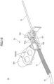
- the thermoelectric couple main body 71 includes a rod-shaped detector 73 protruding in the distal end direction, and a harness 74 for supplying electric power to the detector 73, and the grip 72 is attached to a coupling portion between the detector 73 and the harness 74.
- a well-known temperature detector can be applied to the thermoelectric couple main body 71.
- the grip 72 includes an attachment portion 721 externally mounted on the thermoelectric couple main body 71, a flange portion 723 protruding outward in the width direction at the distal end of the attachment portion 721, and a block portion 724 connected to the upper surface of the attachment portion 721 and inclined upward and in the proximal end direction.
- the attachment portion 721 has two parts 721p which can be divided along the axial direction of the thermoelectric couple main body 71, and is firmly fixed to the thermoelectric couple main body 71 by screwing the two parts 721p with a plurality of coupling screws 722.
- a rectangular marker 10m is provided on the top plate of the work-purpose small table 12.
- the marker 10m serves as an imaging indicator (feature point) for correcting the coordinate positions of the jigs 19 when imaging is performed by the camera 28 mounted on the end effector 25 of the robot 20.
- the marker 10m may be an augmented reality (AR) marker having a three-dimensional position, and thus the robot controller 29 or the control apparatus 4 can recognize a three-dimensional position according to the position of the AR marker recognized by the imaging information.
- the marker 10m is not limited to the AR marker, and may be a mark (for example, a QR code (registered trademark) which can be extracted from the imaging information.
- the marker 10m is not limited to being installed on the workbench 10, and may be installed at a press position of a press apparatus (the heat press apparatus 80 or the cold press apparatus 90), for example.
- the heat press apparatus 80 includes a heat press machine body 81 and a heat press controller 89 (see FIG. 2 ) that controls the operation of the heat press machine body 81.
- the heat press controller 89 controls the operation of the heat press apparatus 80 based on a control command from the control apparatus 4.
- the placement member 822 is provided with a concave arrangement space 822a that substantially matches the shape of the workpiece 59 (see FIG. 8(B) ).
- the concave arrangement space 822a is open on the side where the robot 20 is installed (the Y-axis negative direction side), and the workpiece 59 can be inserted into the concave arrangement space 822a from the open portion while being horizontally slid.
- the peripheral wall of the placement member 822 constituting the concave arrangement space 822a functions as a guide wall 822g that guides the sides of the workpiece 59.
- step S107 the robot controller 29 operates the pair of gripping bodies 27 of the end effector 25 to grip the target jig 19 (the supply cup 61).
- the grip 64 of the supply cup 61 and the center line of the end effector 25 substantially coincide with each other. Therefore, the pair of gripping bodies 27 can accurately grip both side surfaces of the grip 64.
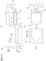
- the control apparatus 4 adjusts the height positions of the fork jig 30 and the workpiece 59 to the height position of the concave arrangement space 822a of the placement portion 82 as illustrated in FIGS. 17(A) and 17(B) . After the height position is adjusted, the control apparatus 4 causes the robot 20 to slide the fork jig 30 and the workpiece 59 in the horizontal direction.
- step S4 the control apparatus 4 outputs a control command to the heat press controller 89, and presses the workpiece 59 (polymer) under the control of the heat press controller 89.
- the heat press apparatus 80 heats the placement portion 82 and the press body 83 to a target temperature with the heater mechanism 84.
- the robot system 20A After the workpiece 59 is placed on the placement portion 82, the robot system 20A returns the fork jig 30 to its original position, and then grips the thermoelectric couple jig 70 and conveys the thermoelectric couple jig 70 to the heat press apparatus 80.
- the robot system 20A can measure the temperature of the polymer by inserting the detector 73 of the thermoelectric couple jig 70 into the measurement-purpose hole 45 of the workpiece 59 (lower plate jig 41).
- the control apparatus 4 can adjust the temperature of the heater mechanism 84 by monitoring the measurement information measured by the thermoelectric couple jig 70.
- the heat press apparatus 80 After the temperature of the polymer reaches the target temperature, the heat press apparatus 80 lowers the press body 83 and presses the workpiece 59 at the set target pressure. Thus, the polymer sandwiched between the lower plate jig 41 and the upper plate jig 51 is pressed and formed into a press-formed product on the heat press apparatus 80.
- step S6 the control apparatus 4 outputs a control command to the cold press controller 99, and presses the workpiece 59 (polymer) for the second time under the control of the cold press controller 99.
- the cold press apparatus 90 heats the placement portion 92 and the press body 93 to a target temperature with the cooling mechanism 94.
- the cold press apparatus 90 lowers the press body 93 and presses the workpiece 59 at the set target pressure.
- the polymer sandwiched between the lower plate jig 41 and the upper plate jig 51 is pressed, and a press-formed product obtained by performing pressing twice is produced as the workpiece 59.
- step S7 the control apparatus 4 operates the robot 20 to grip and convey the fork jig 30, and holds the workpiece 59 on the cold press apparatus 90 with the fork jig 30 and conveys the workpiece 59 to the workbench 10.
- the robot 20 places the workpiece 59 at the original set position of the lower plate jig 41 (the position surrounded by the four holders 17a).
- the original set position of the lower plate jig 41 is also a disassembly position when the workpiece 59 is disassembled.
- step S8 the control apparatus 4 operates the robot 20 to disassemble the workpiece 59 in a procedure reverse to the assembling step.
- the control apparatus 4 performs an operation of taking out the upper plate jig 51 from the lower plate jig 41 and returning the upper plate jig 51 to the original position, and then taking out the intermediate plate jig 46 from the lower plate jig 41 and returning the intermediate plate jig 46 to the original position.
- the press-formed product remains on the upper surface (placement region) of the lower plate jig 41.
- the control apparatus 4 outputs a control command for performing an appropriate analyzing process to the analyzing apparatus 3 to which the press-formed product has been conveyed, thereby analyzing the press-formed product.
- the analysis apparatus 3 captures an image of the press-formed product by an imaging unit (not illustrated), and performs appropriate image processing on the imaging information to calculate the circularity of the press-formed product.
- FIG. 18(A) illustrates the press-formed product P1 having a high circularity
- FIG. 18(B) illustrates the press-formed product P2 having a low circularity.
- the analysis apparatus 3 associates the calculated circularity and thickness of each of the press-formed products P1 and P2, and the like with the conditions of the pressing process (a target pressure of pressing, a heating temperature of the heat press apparatus 80, a length of time of pressing performed by the heat press apparatus 80, a length of time of pressing performed by the cold press apparatus 90, and the like).
- the control apparatus 4 resets the condition parameters of the pressing process (experiment) based on the polymer evaluation value analyzed by the analysis apparatus 3, and reflects the condition parameters to the next sample evaluation method.
- the control apparatus 4 performs the sample evaluation method using the condition parameters of early cycles of the pressing process (experiment), and repeats feedback for resetting the condition parameters of the experiment a plurality of times based on the obtained analysis result of the press-formed product.
- the sample evaluation system 1 can obtain the condition parameters of the pressing process optimal for a sample to be analyzed while significantly reducing a burden on an operator in the evaluation of the sample.
- a robot system comprising:
- the pressing-target object (polymer) is sandwiched between the first plate jig and the second plate jig, and thus it is possible to suppress a positional deviation of the pressing-target object and to improve press accuracy.
- the robot system can guide the workpiece by the guide wall and accurately position the workpiece at the press position.
- the robot system can assemble the workpiece easily and in a short time by switching the jigs between an operation of arranging a pressing-target object on the first plate jig and an operation of overlaying the second plate jig on the first plate jig.
- the robot system can easily perform an operation of arranging the pressing-target object on the first plate jig and an operation of holding the first plate jig and the second plate jig.
- a program configured to cause a computer to function as:
Landscapes
- Engineering & Computer Science (AREA)
- Mechanical Engineering (AREA)
- Robotics (AREA)
- Quality & Reliability (AREA)
- General Health & Medical Sciences (AREA)
- Orthopedic Medicine & Surgery (AREA)
- General Engineering & Computer Science (AREA)
- Manufacturing & Machinery (AREA)
- Health & Medical Sciences (AREA)
- Physics & Mathematics (AREA)
- General Physics & Mathematics (AREA)
- Automation & Control Theory (AREA)
- Manipulator (AREA)
- Press Drives And Press Lines (AREA)
- Casting Or Compression Moulding Of Plastics Or The Like (AREA)
- Automatic Assembly (AREA)
Abstract
Description
- The present disclosure relates to a robot system, a pressing automation system, a program, and a pressing-purpose jig.
- Conventionally, in order to analyze characteristics of a sample, such as a polymer, a polymer (a pressing-target object) is pressed by a press apparatus, and the pressed polymer (a press-molded product) is evaluated. In such an experiment for analyzing a polymer, pressing and evaluation of a polymer is performed a plurality of times while changing the condition parameters of the experiment. Therefore, a large burden is imposed on an operator. Under such a circumstance, there is a demand for development of a system in which a polymer is conveyed using a robot and pressing of the polymer is automatically performed.
-
Patent Document 1 discloses a pressing automation system in which a metal plate is conveyed to a press die unit by a robot and the metal plate is pressed, although this is not a system for sample evaluation. - Patent Document 1:
Japanese Patent No. 6983437 - The present disclosure provides a technique for reducing a work burden on an operator and improving work efficiency.
- According to an aspect of the present disclosure, there is provided a robot system including: an end effector configured to hold a workpiece; an operation device connected to the end effector and configured to operate the end effector; and a control device configured to control an operation of the operation device. The control device controls: a step of assembling the workpiece in a form in which a pressing-target object is sandwiched by arranging the pressing-target object on a first plate jig arranged at a set position and thereafter placing a second plate jig on the first plate jig through operating the end effector; and a step of conveying the workpiece to a press position at which the pressing-target object is pressed by holding the pressing-target object, the first plate jig, and the second plate jig altogether as the workpiece with the end effector.
- According to the above-described robot system, it is possible to smoothly perform pressing at the press position, to reduce a work burden on a user, and to improve work efficiency.
- The control device controls a step of conveying the workpiece to a disassembly position with the end effector by holding the workpiece pressed at the press position, and a step of separating the second plate jig from the first plate jig by operating the end effector at the disassembly position. Thus, the robot system can smoothly disassemble a pressed workpiece at the disassembly position, and can further promote the reduction of a burden on the user and the improvement of work efficiency.
- The press position includes a first position at which the pressing-target object is pressed while being heated, and in the step of conveying the workpiece, the control device causes the workpiece to be conveyed to the first position and, after the workpiece is being pressed, causes the workpiece to be conveyed to the disassembly position. Thus, the robot system can press a pressing-target object (polymer) while heating the pressing-target object at the first position, and then immediately return the workpiece to the disassembly position to obtain a press-formed product.
- The press position includes a first position at which the pressing-target object is pressed while being heated and a second position at which the pressing-target object is pressed while being cooled, and in the step of conveying the workpiece, the control device causes the workpiece to be conveyed to the first position first, and after the workpiece is pressed at the first position, causes the workpiece to be conveyed from the first position to the second position. Thus, the robot system can press a pressing-target object (polymer) while heating a pressing-target object at the first position and then press the pressing-target object while cooling the pressing-target object at the second position. As a result, the robot system can accurately create a press-formed product in accordance with a target temperature.
- The end effector includes an imaging device configured to capture an image of a target object and transmit imaging information to the control device, and the control device controls the end effector to move to a target position based on information of position coordinates of the target object that is held in advance, and corrects a positional deviation of the end effector with respect to the target position based on the imaging information. Thus, the robot system can accurately perform gripping of a target object with the end effector.
- The target object includes a feature point of a workbench on which the first plate jig and the second plate jig are placed or a feature point installed at the press apparatus. Thus, the robot system can smoothly correct the position of the end effector so that the end effector can be located at the feature point.
- In the step of assembling the workpiece, the control device causes the second plate jig to be moved in parallel to a surface direction of the first plate jig so as to face the first plate jig. Thus, the robot system can smoothly assemble the first plate jig and the second plate jig, suppressing a displacement between the first plate jig and the second plate jig.
- One of the first plate jig and the second plate jig has a frame body, and the other of the first plate jig and the second plate jig has a guide surface guided by the frame body, and in the step of assembling the workpiece, the control device causes the guide surface to be into contact with the frame body when causing the second plate jig to be moved with respect to the first plate jig. Thus, even when the second plate jig is displaced from the first plate jig at the time of moving the second plate jig, the robot system can guide and position the relative positions of the first plate jig and the second plate jig by the frame bodies and the guide surface.
- The press position has a concave arrangement space that matches a shape of a distal end of the first plate jig in an entering direction in which the workpiece enters the press position, and in a step of conveying the workpiece to the press position, the control device positions the workpiece by causing the workpiece to be moved in a horizontal direction and bringing the workpiece into contact with a guide wall constituting the concave arrangement space. Thus, when moving the workpiece to the arrangement concave space, the robot system can guide the workpiece by the guide wall and accurately position the workpiece at the press position.
- In a step of assembling the workpiece, the control device causes the pressing-target object to be placed on the first plate jig by causing a cylindrical body to be placed on the first plate jig and subsequently causing the pressing-target object to be placed inside the cylindrical body, and after the cylindrical body is taken out, the control device causes the second plate jig to be arranged on the first plate jig. Thus, the robot system can favorably prevent the pressing-target object from scattering out of the first plate jig in the step of assembling the workpiece.
- The end effector includes a pair of gripping bodies configured to be moved close to and away from each other under an operation command of the control device, and the control device switches a jig having a grip configured to be gripped by the pair of gripping bodies to another jig having a grip in an operation of arranging the pressing-target object on the first plate jig and an operation of overlaying the second plate jig on the first plate jig. Thus, the robot system can assemble the workpiece easily and in a short time by switching the jigs between an operation of arranging a pressing-target object on the first plate jig and an operation of overlaying the second plate jig on the first plate jig.
- The plurality of jigs include a supply cup that accommodates the pressing-target object, and a fork jig having a plurality of forks configured to enter under the first plate jig or the second plate jig and lift the first plate jig or the second plate jig. Thus, the robot system can easily perform an operation of arranging the pressing-target object on the first plate jig and an operation of holding the first plate jig and the second plate jig.
- The plurality of jigs include a temperature detector configured to detect a temperature of the workpiece, and the control device causes the temperature detector to be gripped by the pair of gripping bodies and inserted into the workpiece arranged at the press position. Thus, the robot system can measure a temperature of the pressing-target object by the temperature detector at the time of pressing a workpiece, and can perform pressing at an appropriate temperature.
- Another aspect of the present disclosure, there is provided a pressing automation system includes a robot including an end effector configured to hold a workpiece and an operation device connected to the end effector and configured to operate the end effector, a press apparatus configured to press a pressing-target object accommodated in the workpiece conveyed by the robot, and a control device configured to control the robot and the press apparatus. The control device controls: a step of assembling the workpiece in a form in which a pressing-target object is sandwiched by arranging the pressing-target object on a first plate jig arranged at a set position and thereafter placing a second plate jig on the first plate jig through operating the end effector; a step of conveying the workpiece from the set position to the press apparatus by holding the pressing-target object, the first plate jig, and the second plate jig altogether as the workpiece with the end effector; and a step of pressing the pressing-target object by pressing the first plate jig and the second plate jig by the press apparatus.
- Another aspect of the present disclosure, there is provided a program configured to cause a computer to function as: a robot commander configured to output to a robot system a command to assemble a workpiece in a form in which a pressing-target object is sandwiched by arranging the pressing-target object on a first plate jig arranged at a set position and thereafter placing a second plate jig on the first plate jig through operating an end effector at a set position at which the workpiece is set, and convey the workpiece from the set position to a press apparatus by holding the pressing-target object, the first plate jig, and the second plate jig altogether as the workpiece with the end effector; a press commander configured to output to the press apparatus a command to press the pressing-target object; and an analysis commander configured to output to an analysis apparatus a command to analyze the pressed pressing-target object.
- Another aspect of the present disclosure, there is provided a pressing-purpose jig that is conveyed to a press apparatus while holding a pressing-target object and is pressed by the press apparatus, the pressing-purpose jig including a first plate jig on which the pressing-target object is arranged at a set position, and a second plate jig that forms a workpiece in a form in which the pressing-target object is sandwiched between the first plate jig and the second plate jig by being placed on the first plate jig on which the pressing-target object is arranged. The pressing-purpose jig in a form in which the pressing-target object is sandwiched between the first plate jig and the second plate jig is configured to be conveyed to the press apparatus, and the pressing-purpose jig is configured to press the pressing-target object when the press apparatus presses the first plate jig and the second plate jig the pressing-purpose jig is arranged at the press apparatus.
-
- [
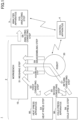
FIG. 1] FIG. 1 is a schematic explanatory diagram illustrating an overall configuration of a sample evaluation system according to an embodiment. - [
FIG. 2] FIG. 2 is a block diagram illustrating modes of communication between a control apparatus and each apparatus. - [
FIG. 3] FIG. 3 is a perspective view illustrating an overall configuration of a pressing automation system. - [
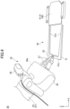
FIG. 4] FIG. 4 is an enlarged perspective view illustrating gripping of an end effector of a robot system. - [
FIG. 5] FIG. 5(A) is a plan view illustrating gripping of the end effector and a fork jig, andFIG. 5(B) is a side view illustrating gripping of the end effector and the fork jig. - [
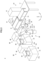
FIG. 6] FIG. 6 is a perspective view illustrating a robot system and a plurality of jigs. - [
FIG. 7] FIG. 7(A) is a plan view illustrating the plurality of jigs on a workbench, andFIG. 7(B) is a plan view illustrating a part of the workbench in an enlarged manner. - [
FIG. 8] FIG. 8(A) is a plan view illustrating pressing-purpose jigs, andFIG. 8(B) is a perspective view illustrating a state in which the pressing-purpose jigs are assembled into a workpiece. - [
FIG. 9] FIG. 9(A) is a perspective view illustrating a supply cup, andFIG. 9(B) is a perspective view illustrating a scatter prevention cup. - [
FIG. 10] FIG. 10 is a perspective view illustrating a thermoelectric couple jig. - [
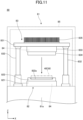
FIG. 11] FIG. 11 is a side view illustrating a press machine body of a heat press apparatus. - [
FIG. 12] FIG. 12 is a perspective view illustrating a placement portion of the heat press apparatus. - [
FIG. 13] FIG. 13 is a block diagram illustrating functional blocks of the control apparatus. - [
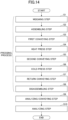
FIG. 14] FIG. 14 is a flowchart illustrating a processing flow of a sample evaluation method. - [
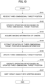
FIG. 15] FIG. 15 is a flowchart illustrating an operation flow when the robot system grips one of the plurality of jigs. - [
FIG. 16] FIG. 16 is a flowchart illustrating steps of assembling a workpiece. - [
FIG. 17] FIG. 17(A) is a side view illustrating an operation when the workpiece is placed on the heat press apparatus, andFIG. 17(B) is a plan view illustrating an operation when a workpiece is placed on the heat press apparatus. - [
FIG. 18] FIG. 18(A) is a view illustrating a press-formed product of a first example, andFIG. 18(B) is a view illustrating a press-formed product of a second example. - [
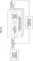
FIG. 19] FIG. 19 is a block diagram illustrating a method of setting experimental parameters for sample evaluation. - Hereinafter, embodiments for implementing the present disclosure will be described with reference to the drawings. In the drawings, the same components are denoted by the same reference numerals, and a duplicate description thereof may be omitted. Note that the X-axis direction, the Y-axis direction, and the Z-axis direction used in the following description are axial directions that intersect perpendicularly to each other. The X-axis direction and the Y-axis direction are horizontal directions, and the Z-axis direction is a vertical direction.
- In order to evaluate a polymer (resin) as a sample, a
sample evaluation system 1 according to an embodiment includes apressing automation system 2 that conveys a polymer to a plurality of work places and performs work such as pressing, and ananalysis apparatus 3 that evaluates a produced press-formed product, as illustrated inFIG. 1 . Thesample evaluation system 1 also includes a control apparatus (control device) 4 that controls each of the apparatuses of thepressing automation system 2 and theanalysis apparatus 3. - The
pressing automation system 2 includes, for example, aworkbench 10, arobot 20, aheat press apparatus 80, and acold press apparatus 90. In thepressing automation system 2, therobot 20 assembles a workpiece containing a polymer (see alsoFIG. 8(B) ) on aworkbench 10. In thepressing automation system 2, therobot 20 sequentially conveys workpieces to two types of press apparatus (theheat press apparatus 80 and the cold press apparatus 90), and each press apparatus presses the polymer to produce a press-formed product. Thepressing automation system 2 is not limited to including two types of press apparatus (theheat press apparatus 80 and the cold press apparatus 90), and may include one type of press apparatus or three or more types of apparatuses. Thepressing automation system 2 may be applied to a press apparatus that does not heat or cool a polymer, or may be configured to press a polymer by adjusting a temperature to a plurality of temperatures in one press apparatus. - As illustrated in
FIG. 2 , thecontrol apparatus 4 includes one ormore processors 4a, amemory 4b, an input/output interfaces 4c, and acommunication interface 4d, and is configured as a computer that controls the entiresample evaluation system 1. The one ormore processors 4a are one or a combination of a plurality of central processing units (CPUs), graphics processing units (GPUs), application specific integrated circuits (ASICs), field-programmable gate arrays (FPGAs), circuits formed of a plurality of discrete semiconductors, and the like. Thememory 4b includes a nonvolatile memory and a volatile memory (for example, a compact disc, a digital versatile disc (DVD), hard disk, flash memory, and the like), and constitutes a storage unit of thecontrol apparatus 4. - The input/
output interface 4c is connected to an input/output apparatus 5, which is an operator interface that can be operated and checked by an operator of thesample evaluation system 1. As the input/output apparatus 5, for example, a monitor, a mouse, a keyboard, a touch panel (including a tablet terminal, a smartphone, and the like), a speaker, a microphone, and the like can be appropriately adopted. - The
communication interface 4d performs information communication between each of therobot 20, theheat press apparatus 80, thecold press apparatus 90, and theanalysis apparatus 3, and thecontrol apparatus 4 via acommunication network 6 capable of wired communication or wireless communication. Thecommunication network 6 may be any one of a wide area network (WAN), a local area network (LAN), a personal area network (PAN), and the like, or a combination thereof. Examples of WANs include the Internet, examples of LANs include IEEE 802.11 and Ethernet (registered trademark), and examples of PANs include Bluetooth (registered trademark) and near field communication (NFC). - The
robot 20 is provided with arobot controller 29 that communicates information with thecontrol apparatus 4 and operates therobot 20. Theheat press apparatus 80 is provided with aheat press controller 89 that communicates information with thecontrol apparatus 4 and operates theheat press apparatus 80. Thecold press apparatus 90 is provided with acold press controller 99 that communicates information with thecontrol apparatus 4 and operates thecold press apparatus 90. Theanalysis apparatus 3 is provided with an analysis-purpose controller 3c that communicates information with thecontrol apparatus 4 and operates theanalysis apparatus 3. - The
memory 4b of thecontrol apparatus 4 stores aprogram 100 for controlling thesample evaluation system 1. Theprogram 100 is read and executed by theprocessor 4a, thereby forming a plurality of functional units for controlling the entiresample evaluation system 1 in thecontrol apparatus 4. In thecontrol apparatus 4, the respective functional units formed under the execution of theprogram 100 outputs control commands to the pressing automation system 2 (therobot 20, theheat press apparatus 80, and the cold press apparatus 90) and theanalysis apparatus 3 at appropriate timings. In other words, theprogram 100 functions as bridge software that achieves the creation of press-formed products by thepressing automation system 2 in conjunction with the analysis of the press-formed products by theanalysis apparatus 3. - Although
FIG. 2 illustrates one computer as thecontrol apparatus 4 of thesample evaluation system 1, software may be installed in a plurality of computers, and the plurality of computers may execute the same or different partial processing of the software. In this case, the distributed computing may be adopted in which the computers communicate with each other to execute the processing. As an example, thecontrol apparatus 4 can be configured by a computer for a robot operating system (ROS) connected to each apparatus and a plurality of control computers connected to the computer of the ROS. Thecontrol apparatus 4 of thesample evaluation system 1 may be configured to process information transmitted from a terminal device with one or more computers provided on the cloud and transmit the processing result to the terminal device. - As illustrated in
FIG. 3 , thepressing automation system 2 includes aworkbench 10, theheat press apparatus 80, and thecold press apparatus 90, which are arranged around therobot 20. Theworkbench 10, theheat press apparatus 80, and thecold press apparatus 90 are installed so as to form an L shape in a plan view (see alsoFIG. 1 ). Theworkbench 10 is formed in a rectangular shape extending long along the Y-axis direction at a position away from therobot 20 in the X-axis direction. Theheat press apparatus 80 and thecold press apparatus 90 are installed at positions away from therobot 20 in the Y-axis direction so as to be arranged along the X-axis direction. The arrangement of theworkbench 10 and the apparatuses of thepressing automation system 2 is not limited to an L-shape, and may be set at an operator's discretion. - The
workbench 10 forms a work place where therobot 20 assembles and disassembles a workpiece containing a polymer in thepressing automation system 2. For example, theworkbench 10 includes abase 11, a work-purpose small table 12 installed on thebase 11, and a conveying-purpose small table 13 installed on the base 11 so as to be aligned with the work-purpose small table 12 in the Y-axis direction. Theworkbench 10 may be a single table (the base 11 in which the work-purpose small table 12 and the conveying-purpose small table 13 are seamlessly connected in series). - The
base 11 includes a top plate having a rectangular, flat shape in a plan view and a plurality of leg portions supporting the top plate. Thebase 11 is installed in such a manner that the long side of the top plate is along the Y-axis direction. On the top plate of thebase 11, a weighingdevice 14, aremoval apparatus 15, and the like are installed, in addition to the work-purpose small table 12 and the conveying-purpose small table 13. - The work-purpose small table 12 is a table for assembling and disassembling a workpiece containing a polymer. The
pressing automation system 2 includes a plurality of types of jigs (targets for gripping) 19 for assembling and disassembling a workpiece and are provided on the upper surface of the work-purpose small table 12. The plurality of types ofjigs 19 will be described in detail later. The conveying-purpose small table 13 forms a place where a press-formed product that is produced in thepressing automation system 2 is separated from the jig 19 (a lower plate jig 41) and is kept on standby until the press-formed product is conveyed to theanalysis apparatus 3. - The work surface (upper surface) of the work-purpose small table 12 and the work surface (upper surface) of the conveying-purpose small table 13 are set at a height at which an
end effector 25 of therobot 20 can reach. Thebase 11, the work-purpose small table 12, and the conveying-purpose small table 13 may include an adjuster (not illustrated) capable of adjusting the height and parallelism of each upper surface (for example, a level adjuster). - The weighing
device 14 is installed at a position adjacent to the work-purpose small table 12, and weighs a polymer as a pressing-target object. For example, the weighingdevice 14 includes a box-shaped case, and a measurer for measuring a weight of a polymer is provided on the bottom surface of the case. The measurer is connected to thecontrol apparatus 4 via thecommunication network 6, and automatically transmits measurement information (a weight of a polymer) to thecontrol apparatus 4. The surface of the case of the weighingdevice 14 on the side close to therobot 20 is open so that theend effector 25 of therobot 20 can enter the case. For example, therobot 20 tilts a container of a granulated polymer, with a supply cup 61 (seeFIG. 6 ) being placed on the measurer. Thesupply cup 61 is one of thejigs 19 and will be described later. Thecontrol apparatus 4 supplies an appropriate amount of polymer to thesupply cup 61 by instructing an operation of therobot 20 while monitoring the measurement information of the measurer. - The
removal apparatus 15 is installed at a position adjacent to the conveying-purpose small table 13, and when a press-formed product is adhered to thejig 19, theremoval apparatus 15 peels the press-formed product from thejig 19 and takes out the press-formed product. As theremoval apparatus 15, a conventional die cutting device, ejector device, or the like can be applied. - The
robot 20 of thepressing automation system 2 includes anoperation device 21 and theend effector 25 that is moved to a target three-dimensional position by theoperation device 21. Therobot 20 operates theoperation device 21 and theend effector 25 based on a control command of thecontrol apparatus 4. Therefore, in the present embodiment, a system in which thecontrol apparatus 4 and therobot 20 are combined is also referred to as a "robot system 20A". - The
operation device 21 of therobot 20 is configured as a vertical articulated type including abase 22, a plurality ofarms 23 arranged on thebase 22, and a plurality ofjoints 24 connecting thearms 23 to each other. Three or more (for example, seven in the present embodiment)arms 23 are provided, and eacharm 23 has awrist 231 on the distal end side. - The plurality of
joints 24 are provided between thearms 23 adjacent to each other, and move thearm 23 on the distal end side in relation to thearm 23 on the base 22 side. Therobot 20 includes a joint motor in each of thebase 22 and the joints 24 (or the arms 23). Therobot 20 includes a plurality of motor drivers that supply electric power to the joint motors under the control of therobot controller 29, and operates thejoints 24 independently. - As illustrated in
FIG. 4 , theend effector 25 of therobot 20 is attached to the distal end of a series of the plurality of arms 23 (the wrist 231). Theend effector 25 according to the present embodiment employs a clamp mechanism that grips thejig 19, which is a gripping-target object, with a set (pair) of grippingbodies 27. Specifically, theend effector 25 includes arectangular parallelepiped housing 26 fixed to thewrist 231, and the pair ofgripping bodies 27 is arranged on a distal end surface (tip surface) of thehousing 26. A grippingbody operation device 26a that operates the pair ofgripping bodies 27 is provided in thehousing 26. The grippingbody operation device 26a includes a motor, a plurality of gears, and the like (not illustrated), and moves the pair ofgripping bodies 27 closer together or away from each other along the longitudinal direction of the distal end surface, under the control of therobot controller 29. - The pair of
gripping bodies 27 includesbase end portions 271 accommodated in thehousing 26,middle portions 272 each of which is continuous with a tip end of thebase end portion 271 and is inclined in a direction of being narrowed inward, and protrudingend portions 273 each of which is continuous with a tip end of themiddle portion 272 and extends in parallel to thebase end portion 271. When the pair ofgripping bodies 27 is closed by the grippingbody operation device 26a, the pair ofgripping bodies 27 can grip a gripping-target object arranged between theprotruding end portions 273 and move the gripping-target object under the operation of theoperation device 21. The gripping-target object gripped by the pair ofgripping bodies 27 is any one of a plurality of jigs 19 (described later) arranged on theworkbench 10, and afork jig 30 is illustrated inFIG. 4 . - In the robot system 20A, a holding
structure 33 is formed in theend effector 25 and the plurality ofjigs 19. Each of the plurality ofjigs 19 has a structure (agrip 32 of thefork jig 30 inFIG. 4 ) held by the pair ofgripping bodies 27. - As illustrated in
FIGS. 5(A) and 5(B) , each of thegripping bodies 27 of theend effector 25 has a plurality of (two) gripping-purpose protrusions 274 on the inner facing surface of theprotruding end portion 273, serving as part of the holdingstructure 33. Each of the gripping-purpose protrusions 274 is integrally formed with the grippingbody 27 by a metal material. Each of the gripping-purpose protrusions 274 protrudes short from the facing surface of each of thegripping bodies 27, and the outerperipheral surface 274c thereof is formed in a conical shape that tapers from the facing surface of one of thegripping bodies 27 connected to the gripping-purpose protrusions 274 to the other gripping body 27 (in the protruding direction). The two gripping-purpose protrusions 274 are provided side by side along the protruding direction of theprotruding end portion 273. - The
grip 32 of thefork jig 30 is projected obliquely from the upper surface of the forkmain body 31. Thegrip 32 is formed of a metal material in a wide block shape, and has rigidity so as not to be deformed even in a state of being gripped by the pair ofgripping bodies 27. Thegrip 32 includes a plurality of (two) gripping-purpose recesses 321 recessed in each of the pair of side surfaces, serving as the other part of the corresponding holdingstructure 33. The innerperipheral surface 321t of each gripping-purpose recess 321 is formed in a tapered shape (conical funnel shape) in which the diameter decreases from the opening in the depth direction. The inclination of the innerperipheral surface 321t substantially matches the inclination of the outerperipheral surface 274c of thegripping body 27. The two gripping-purpose recesses 321 are provided side by side along the protruding direction of thegrip 32. - To grip the target jig 19 (the
fork jig 30 inFIG. 5 ), therobot 20 positions the pair ofgripping bodies 27 so as to face both side surfaces of thegrip 32, and then brings thegripping bodies 27 close to each other. When thegripping bodies 27 are close to each other, the gripping-purpose protrusions 274 enter the gripping-purpose recesses 321 respectively, while the conical outerperipheral surfaces 274c of the gripping-purpose protrusions 274 are being guided by the tapered innerperipheral surfaces 321t of the gripping-purpose recesses 321. Thus, the gripping-purpose protrusions 274 and the gripping-purpose recesses 321 are fitted to each other, and the opposing surfaces of the pair ofgripping bodies 27 come into contact with both side surfaces of thegrip 32 to hold thegrip 32 therebetween. Moreover, in a state where the pair ofgripping bodies 27 hold thegrip 32, as illustrated inFIG. 5(B) , the two gripping-purpose protrusions 274 and the two gripping-purpose recesses 321 are engaged with each other on each of both side surfaces. For this reason, the holdingstructure 33 can restrict the rotation of the grip 32 (that is, the gripping-target object (jig 19) being gripped) with respect to theend effector 25. Therefore, even when a load is applied from the main body of thejig 19 or the like, theend effector 25 can firmly grip thejig 19. - Returning to
FIG. 4 , in the robot system 20A according to the present embodiment, a camera (imaging unit) 28 is installed in thehousing 26 of theend effector 25. Thecamera 28 is a compound-eye imaging device, captures an image of a portion ahead of the pair ofgripping bodies 27, and transmits each piece of imaging information to the control apparatus 4 (or the robot controller 29). Thecontrol apparatus 4 recognizes amarker 10m or the like on theworkbench 10 based on each piece of imaging information transmitted from thecamera 28. Thecontrol apparatus 4, in principle, operates the plurality ofjoints 24 based on a three-dimensional target position (position coordinates) that is set in advance to move theend effector 25. When theend effector 25 approaches the three-dimensional target position, thecontrol apparatus 4 corrects the movement of theend effector 25 based on the three-dimensional position extracted from each piece of imaging information. Accordingly, the robot system 20A can accurately guide theend effector 25 to a target indicator (for example, the center line of the grip 32) of the gripping-target object (the jig 19) and stably grip the gripping-target object by the pair ofgripping bodies 27. - Next, the plurality of
jigs 19 prepared in thepressing automation system 2 will be described in detail. As illustrated inFIG. 6 , the robot system 20A moves theend effector 25 relative to the work-purpose small table 12, and assembles a workpiece containing a polymer by using the plurality ofjigs 19 that are set on the work-purpose small table 12. - A
fork jig 30, pressing-purpose jigs 40, acup jig 60, and a thermoelectric couple jig (temperature detector) 70 are set in advance on the work-purpose small table 12 as a plurality ofjigs 19. The pressing-purpose jigs 40 are main jigs that make up a workpiece containing a polymer, and include a lower plate jig (first plate jig) 41, anintermediate plate jig 46, and an upper plate jig (second plate jig) 51. Thecup jig 60 is a jig for placing a polymer on thelower plate jig 41, and includes thesupply cup 61 and ascatter prevention cup 66. Further, a punching-purpose conveyance table 16 for disassembling a workpiece containing a press-formed product after pressing and conveying the press-formed product to theremoval apparatus 15 is installed in the work-purpose small table 12 in advance. - As illustrated in
FIGS. 6 and7(A) , the work-purpose small table 12 has a rectangulartop plate 121, and awork surface 12s on which the punching-purpose conveyance table 16 and thejigs 19 can be set is formed on thetop plate 121. On the side closer to therobot 20 in the direction along the short side of the work-purpose small table 12 (the X-axis direction), theupper plate jig 51, thelower plate jig 41, theintermediate plate jig 46, and the punching-purpose conveyance table 16 are arranged in this order in the negative Y-axis direction. Thethermoelectric couple jig 70, thefork jig 30, thescatter prevention cup 66, and thesupply cup 61 are arranged in this order in the negative Y-axis direction on the side away from therobot 20 in the direction along the short side of the work-purpose small table 12. Thejigs 19 can of course be arranged in an order at an operator's discretion. - A plurality of
holders 17 for holding the punching-purpose conveyance table 16 andrespective jigs 19 are installed on thework surface 12s. Eachholder 17 is screwed to thetop plate 121 by screwing a plurality of fixingscrews 18 into a plurality ofscrew holes 12h formed on thework surface 12s through through holes (not illustrated) of eachholder 17. The plurality ofscrew holes 12h are formed at regular intervals (for example, 30 mm), and are arranged in a matrix form in which a plurality of screw holes are arranged in the X-axis direction and the Y-axis direction as a whole. - Each
holder 17 is formed in an appropriate shape in accordance with the shapes of the punching-purpose conveyance table 16 and eachjig 19. For example, as illustrated inFIG. 7(B) , to hold theupper plate jig 51, fourholders 17a each having afirst step portion 171 fixed by the fixingscrew 18 and asecond step portion 172, which is continuous with thefirst step portion 171 and is formed lower than thefirst step portion 171, are used. - Two of the four
holders 17a are fixed at positions at which both side portions of theupper plate jig 51 in the X-axis direction (side portions opposite to the side portions on the installation side of the robot 20) can be supported, and the remaining twoholders 17a are fixed at positions at which both side portions of theupper plate jig 51 in the Y-axis direction can be supported. Theupper plate jig 51 is configured to stand by, when it is in a set state, in a state of being slightly floated from thework surface 12s by the lower surface of theupper plate jig 51 being supported by thesecond step portions 172 of therespective holders 17a while the side edges of theupper plate jig 51 are close to or in contact with thefirst step portions 171. Thelower plate jig 41 and the punching-purpose conveyance table 16 are also held by fourholders 17a fixed to thework surface 12s in accordance with the shapes thereof, similarly to theupper plate jig 51. Being held by threeholders 17a on one side in the X-axis direction and both sides in the Y-axis direction, theintermediate plate jig 46 is held by aholder 17b that can cover the periphery of thegrip 48. - For example, each of the
fork jig 30, the cup jig 60 (thesupply cup 61 and the scatter prevention cup 66), and thethermoelectric couple jig 70 is held by arectangular parallelepiped holder 17b capable of covering the periphery thereof. Theholder 17b has a holding groove corresponding to the shape of the jigs, and each of the jigs is accommodated in the holding groove and held horizontally immovable. - As illustrated in
FIG. 4 , in a state of being gripped by theend effector 25 of therobot 20, thefork jig 30 enters under the lower surface of theupper plate jig 51 by the movement of theend effector 25, thereby holding theupper plate jig 51. Thefork jig 30 enters the lower surface side of thelower plate jig 41 by the movement of theend effector 25 in a state of being gripped by theend effector 25 of therobot 20, thereby holding thelower plate jig 41. - As described above, the
fork jig 30 is configured by connecting the forkmain body 31 and thegrip 32. The forkmain body 31 includes a pair of (two) rod-shapedflat plates 31a extending substantially parallel to each other, and a connectingflat plate 31b connecting the proximal portions of the pair of rod-shapedflat plates 31a. Each of the rod-shapedflat plates 31a is, for example, gradually narrowed from the connecting portion of the connectingflat plates 31b toward the distal end, and the distal end is formed into a rounded corner. - The
grip 32 is fixed to the upper surface of the connectingflat plate 31b by an appropriate fixing means, such as screwing or welding. Thegrip 32 is inclined with respect to the forkmain body 31 in an angle range of, for example, about 20° to 70°, and have two gripping-purpose recesses 321 on each of both side surfaces thereof as described above. Therefore, in a state where thefork jig 30 is accommodated in theholder 17b, thegrip 32 protrudes upward in the negative X-axis direction (positive Z-axis direction) from the upper surface of theholder 17b. Thus, theend effector 25 can easily access thegrip 32, and thefork jig 30 can be pulled out from theholder 17b by moving theend effector 25 upward while gripping thegrip 32. - As illustrated in
FIGS. 8(A) and 8(B) , the pressing-purpose jigs 40 are jigs that make up aworkpiece 59 containing a polymer by placing the polymer on thelower plate jig 41 and further stacking theintermediate plate jig 46 and theupper plate jig 51 in this order.FIG. 8(A) illustrates thelower plate jig 41 and theintermediate plate jig 46 for their upper surface (flat surface) side, whereas theupper plate jig 51 is illustrated for its lower surface side, for easy understanding. - In other words, the
pressing automation system 2 according to the present embodiment holds a polymer in the vertical direction by sandwiching the polymer between thelower plate jig 41 and theupper plate jig 51. Further, thepressing automation system 2 prevents a polymer from slipping off in the lateral direction by theintermediate plate jig 46 arranged between thelower plate jig 41 and theupper plate jig 51. Thepressing automation system 2 is configured to convey a polymer in the form of the workpiece 59 (in a state where the polymer is sandwiched between thelower plate jig 41 and the upper plate jig 51) to theheat press apparatus 80 and thecold press apparatus 90 and press the polymer in the sandwiched state at the time of pressing. The pressing-purpose jigs 40 may be configured such that the polymer is sandwiched between thelower plate jig 41 and theupper plate jig 51 without using theintermediate plate jig 46. - Specifically, the
lower plate jig 41 includes aplate body 42 formed in a plate shape thicker than the forkmain body 31 of thefork jig 30, and a plurality offrame bodies 43 protruding from the upper surface of theplate body 42. A pair of holdinggrooves 44 are formed in the lower surface of thelower plate jig 41. Further, a measurement-purpose hole 45 into which thethermoelectric couple jig 70 is inserted is formed at a middle position in the width direction of thelower plate jig 41. - The
plate body 42 is formed in a polygonal shape (hexagonal shape) in which the trapezoidal shape on the distal end side (X-axis positive direction side) is continuous with the rectangular shape on the proximal end side (X-axis negative direction side), in a plan view. The distal end side of theplate body 42 hasopposite sides 42a which are close to each other toward the distal end direction, and eachopposite side 42a is continuous with thedistal end side 42b. - In the upper surface of the
plate body 42, a portion located inside theframe bodies 43 is formed in a flat shape. When theworkpiece 59 is assembled, a polymer is placed on the placement region in this inside portion. A pair ofstoppers 42d for restricting a movement of theplate body 42 in the distal direction are attached to thebase end slide 42c of theplate body 42. Theplate body 42 may have a shape in which a part thereof is cut out in order to reduce the weight of the entirelower plate jig 41. - The plurality of
frame bodies 43 are provided on four sides (both sides in the X-axis direction and both sides in the Y-axis direction) of theplate body 42, and extend in parallel to the respective sides. Eachframe body 43 has aslope 431 that is inclined toward the plate body 42 (downward) from the outside toward the inside. - The pair of (two) holding
grooves 44 linearly extend from thebase end side 42c of theplate body 42 in the distal end direction. The pair of rod-shapedflat plates 31a of thefork jig 30 enters the pair of holdinggrooves 44 from the open portion of thebase end side 42c. Each of the holdinggrooves 44 is formed to be slightly wider than the rod-shapedflat plates 31a and to be gradually narrower toward the tip end, and can accommodate most of each of the rod-shapedflat plates 31a. Thelower plate jig 41 is supported by thefork jig 30 inserted into the pair of holdinggrooves 44 in a state being maintained to be horizontal. - The measurement-
purpose hole 45 extends linearly inside theplate body 42 from thebase end side 42c in the distal end direction. Thedetector 73 of thethermoelectric couple jig 70 is inserted into the measurement-purpose hole 45 when theworkpiece 59 is placed at the press position of theheat press apparatus 80 or the press position of thecold press apparatus 90. Thus, the temperature of the placement region of the plate body 42 (in other words, the temperature of the polymer supplied to the placement region) can be measured. - The
intermediate plate jig 46 of the pressing-purpose jigs 40 is first arranged on theplate body 42 of thelower plate jig 41, thereby defining a polymer placement region. Theintermediate plate jig 46 includes aplate body 47 having a plate shape thinner than theplate body 42 of thelower plate jig 41, and agrip 48 connected to theplate body 47 via aconnection portion 49. Acircular hole 47h for defining a placement region is formed in theplate body 47 of theintermediate plate jig 46. - Similarly to the
plate body 42, theplate body 47 is formed in a polygonal shape (hexagonal shape) in which the trapezoidal shape on the distal end side (X-axis positive direction side) is continuous with the rectangular shape on the proximal end side (X-axis negative direction side), in a plan view. Theplate body 47 is formed to be smaller than theplate body 42 in a plan view, and can be arranged inside the plurality offrame bodies 43. The distal end side of theplate body 47 hasopposite sides 47a which are close to each other toward the distal end, and eachopposite side 47a is continuous with the distal end side 47b. - The
grip 48 protrudes in a direction orthogonal to the plane of the plate body 47 (Z-axis positive direction). Thegrip 48 is formed in a block shape, similarly to thegrip 32 of thefork jig 30, and has a pair of (two) gripping-purpose recesses 481 on each side surfaces thereof. The gripping-purpose recesses 481 constitute one part of the holdingstructure 33 which the gripping-purpose protrusions 274 provided on the pair ofgripping bodies 27 enter when thegrip 48 is gripped by theend effector 25. - The
upper plate jig 51 of the pressing-purpose jigs 40 is placed on theplate body 47 of theintermediate plate jig 46 after a polymer is supplied to the placement region of thelower plate jig 41. Theupper plate jig 51 includes aplate body 52 having a thickness substantially equal to that of thelower plate jig 41. A pair of holdinggrooves 53 are formed in the lower surface of theupper plate jig 51. - The
plate body 52 is formed in a polygonal shape (hexagonal shape) in which the trapezoidal shape on the distal end side (X-axis positive direction side) is continuous with the rectangular shape on the proximal end side (X-axis negative direction side), in a plan view. The distal end side of theplate body 42 hasopposite sides 52a which are close to each other toward the distal end direction, and eachopposite side 52a is continuous with thedistal end side 52b. In the present embodiment, the shape of theplate body 52 of theupper plate jig 51 substantially matches the shape of theplate body 42 of thelower plate jig 41. - Each side of the
plate body 52 is formed with aguide surface 54 inclined inward from the upper surface toward the lower surface. When theupper plate jig 51 is placed on thelower plate jig 41, theguide surface 54 of theplate body 52 comes into contact with theinclined surfaces 431 of the plurality offrame bodies 43 to guide theupper plate jig 51 to a relative position of with respect to thelower plate jig 41. - The pair of (two) holding
grooves 53 linearly extend from theguide surface 54 on the base end side of theplate body 52 toward the distal end. The pair of rod-shapedflat plates 31a of thefork jig 30 enters the pair of holdinggrooves 53. Theupper plate jig 51 is supported by thefork jig 30 inserted into the pair of holdinggrooves 53 in a state being maintained to be horizontal. - The pressing-purpose jigs 40 described above are assembled into the
workpiece 59 as illustrated inFIG. 8(B) by the robot 20 (seeFIG. 6 ). In the form of theworkpiece 59, theintermediate plate jig 46 and theupper plate jig 51 overlap thelower plate jig 41, and theframe bodies 43 in the circumferential direction of thelower plate jig 41 and the guide surfaces 54 in the circumferential direction of theupper plate jig 51 brought closer to each other. Therefore, it is possible to regulate the displacement of theupper plate jig 51 in the surface direction with respect to thelower plate jig 41. A polymer is sandwiched between theplate body 42 of thelower plate jig 41 and theplate body 52 of theupper plate jig 51. Thepressing automation system 2 can convey thelower plate jig 41, theintermediate plate jig 46, and theupper plate jig 51 in a form of theworkpiece 59, into which these jigs are integrated, from theworkbench 10 by holding thelower plate jig 41 with therobot 20 through thefork jig 30. - The
supply cup 61 of thecup jig 60 includes acup body 62 and agrip 64 connected to the outside of thecup body 62 as illustrated inFIG. 9(A) , and is used to supply a polymer to the placement region of thelower plate jig 41. - The
cup body 62 is formed by acircular bottom portion 621 and aconical side portion 622 which is inclined upward and outward from the edge of thebottom portion 621, and has anaccommodation space 63 inside thebottom portion 621 and theside portion 622. In other words, an innerperipheral surface 62i of thecup body 62 forming theaccommodation space 63 is formed in a tapered shape. Since the opening of theaccommodation space 63 is wide, thecup body 62 can contain a polymer to be measured by the weighing device 14 (seeFIG. 3 ) without spilling the polymer into theaccommodation space 63. - The
grip 64 has acoupling portion 641 coupled to theside portion 622 of thecup body 62 and ablock portion 642 projecting from one end portion of thecoupling portion 641 in a direction orthogonal to thebottom portion 621 of the cup body 62 (Z-axis positive direction), and has an L shape in a side view. Thegrip 64 also has a pair of (two) gripping-purpose recesses 643 on both side surfaces of theblock portion 642, similarly to thegrip 32 of thefork jig 30. The gripping-purpose recesses 643 makes up one part of the holdingstructure 33 which each of the gripping-purpose protrusions 274 provided on the pair ofgripping bodies 27 enters when thegrip 48 is gripped by theend effector 25. - As illustrated in
FIG. 9(B) , thescatter prevention cup 66 of thecup jig 60 has acup body 67 and agrip 69 connected to the outside of thecup body 67. Thescatter prevention cup 66 is arranged in the placement region of thelower plate jig 41 and prevents a polymer from scattering when the polymer is supplied by thesupply cup 61. - The
cup body 67 is formed of acylindrical body 671 having no bottom portion, and has apenetration space 68 penetrating in the vertical direction (Z-axis direction) inside thecylindrical body 671. In other words, the innerperipheral surface 67i of thecup body 67 forming thepenetration space 68 extends in the vertical direction with a constant inside diameter. A polymer is put from thesupply cup 61 into thepenetration space 68 of thecup body 67 arranged in thelower plate jig 41. At this time, thecup body 67 can prevent the polymer from scattering out of thecylindrical body 671. The member for preventing the polymer from scattering when the polymer is supplied to thelower plate jig 41 is not limited to the above-described configuration, and various configurations can be adopted. For example, thescatter prevention cup 66 may be configured in such a manner that a plate having substantially the same shape as theintermediate plate jig 46 is connected to the outer peripheral surface of thecylindrical body 671 and the plate is brought into contact with theintermediate plate jig 46. The plate enables thescatter prevention cup 66 to reliably prevent thecylindrical body 671 from falling. - The
grip 69 has acoupling portion 691 coupled to thecylindrical body 671 of thecup body 67 and ablock portion 692 protruding from one end of thecoupling portion 691 in a direction parallel to the cylindrical body 671 (Z-axis positive direction), and has an L shape in a side view. Thegrip 69 is also has, similarly to thegrip 32 of thefork jig 30, a pair of (two) gripping-purpose recesses 693 on both side surfaces of theblock portion 692. The gripping-purpose recesses 693 constitute one part of the holdingstructure 33 which the gripping-purpose protrusions 274 provided on the pair ofgripping bodies 27 enter when thegrip 48 is gripped by theend effector 25. - As illustrated in
FIG. 10 , when theworkpiece 59 is placed on theheat press apparatus 80 or thecold press apparatus 90, thethermoelectric couple jig 70 is inserted into the measurement-purpose hole 45 of thelower plate jig 41 to measure the temperature of a polymer. Thethermoelectric couple jig 70 includes a thermoelectric couplemain body 71 and agrip 72 attached to the thermoelectric couplemain body 71. - The thermoelectric couple
main body 71 includes a rod-shapeddetector 73 protruding in the distal end direction, and aharness 74 for supplying electric power to thedetector 73, and thegrip 72 is attached to a coupling portion between thedetector 73 and theharness 74. A well-known temperature detector can be applied to the thermoelectric couplemain body 71. - The
grip 72 includes anattachment portion 721 externally mounted on the thermoelectric couplemain body 71, aflange portion 723 protruding outward in the width direction at the distal end of theattachment portion 721, and ablock portion 724 connected to the upper surface of theattachment portion 721 and inclined upward and in the proximal end direction. Theattachment portion 721 has twoparts 721p which can be divided along the axial direction of the thermoelectric couplemain body 71, and is firmly fixed to the thermoelectric couplemain body 71 by screwing the twoparts 721p with a plurality of coupling screws 722. - The
block portion 724 of thegrip 72 is inclined upward in the proximal end direction, similarly to thegrip 32 of thefork jig 30. Two gripping-purpose recesses 725, which serve one part of the holdingstructure 33, are provided on each of both side surfaces of theblock portion 724. Thethermoelectric couple jig 70 formed in such a manner is in a state where thegrip 72 protrudes from the upper surface of theholder 17b in a state where thethermoelectric couple jig 70 is accommodated in theholder 17b, and thus theend effector 25 of therobot 20 can easily access the thermoelectric couple jig 70 (seeFIG. 6 ). - As illustrated in
FIGS. 6 and7(A) , arectangular marker 10m is provided on the top plate of the work-purpose small table 12. Themarker 10m serves as an imaging indicator (feature point) for correcting the coordinate positions of thejigs 19 when imaging is performed by thecamera 28 mounted on theend effector 25 of therobot 20. Themarker 10m may be an augmented reality (AR) marker having a three-dimensional position, and thus therobot controller 29 or thecontrol apparatus 4 can recognize a three-dimensional position according to the position of the AR marker recognized by the imaging information. Themarker 10m is not limited to the AR marker, and may be a mark (for example, a QR code (registered trademark) which can be extracted from the imaging information. Themarker 10m is not limited to being installed on theworkbench 10, and may be installed at a press position of a press apparatus (theheat press apparatus 80 or the cold press apparatus 90), for example. - Returning to
FIG. 3 , theheat press apparatus 80 and thecold press apparatus 90 for actually pressing a workpiece containing a polymer will be described. Theheat press apparatus 80 includes a heatpress machine body 81 and a heat press controller 89 (seeFIG. 2 ) that controls the operation of the heatpress machine body 81. Theheat press controller 89 controls the operation of theheat press apparatus 80 based on a control command from thecontrol apparatus 4. - As illustrated in
FIG. 11 , the heatpress machine body 81 includes aplacement portion 82 that forms a press position (first position) for theworkpiece 59 on the upper surface of themachine body housing 81a, and apress body 83 that can approach and separate from theplacement portion 82. Further, a press operation mechanism (not illustrated) for operating thepress body 83 is provided inside themachine body housing 81a. The heatpress machine body 81 may include a cover 85 (see the dotted line inFIG. 11 ) that covers theplacement portion 82 and thepress body 83. - The
placement portion 82 includes a fixing table 821 and aplacement member 822 which is a portion fixed to the upper surface of the fixing table 821 and on which theworkpiece 59 is directly placed. Aheater mechanism 84 for heating theworkpiece 59 via theplacement member 822 is provided inside the fixing table 821. - As illustrated in
FIG. 12 , theplacement member 822 is provided with aconcave arrangement space 822a that substantially matches the shape of the workpiece 59 (seeFIG. 8(B) ). Theconcave arrangement space 822a is open on the side where therobot 20 is installed (the Y-axis negative direction side), and theworkpiece 59 can be inserted into theconcave arrangement space 822a from the open portion while being horizontally slid. The peripheral wall of theplacement member 822 constituting theconcave arrangement space 822a functions as aguide wall 822g that guides the sides of theworkpiece 59. Theguide wall 822g in the innermost area of theconcave arrangement space 822a is formed in a shape that matches theopposite sides 42a and thedistal end side 42b of thelower plate jig 41 and theopposite sides 52a and thedistal end side 52b of theupper plate jig 51. - For this reason, when the
workpiece 59 is placed on theplacement portion 82, theworkpiece 59 enters the innermost area of theconcave arrangement space 822a while being guided by theguide wall 822g as therobot 20 slides theworkpiece 59. Theworkpiece 59 can be accurately positioned at the press position of theplacement portion 82 by bringing the distal end sides 42b and 52b of theworkpiece 59 into contact with theinnermost guide wall 822g. - The
press body 83 is moved up and down relative to theplacement portion 82 by a press operation mechanism in themachine body housing 81a. As illustrated inFIG. 11 , thepress body 83 includes amovable board 831, a plurality of (four) support posts 832 that support themovable board 831 in an elevatable/lowerable manner, apress support portion 833 installed on the lower surface of themovable board 831, and apresser 834 fixed to thepress support portion 833. Thepress body 83 includes aheater mechanism 84 in thepress support portion 833, and theheater mechanism 84 heats thepresser 834. Themovable board 831 may include aheat radiation fin 835 for radiating heat (of the press support portion 833) on the upper surface. - Each of the support posts 832 protrudes from the inside of the
machine body housing 81a, and is connected to the press operation mechanism in themachine body housing 81a. The press operation mechanism includes a drive source (not illustrated), such as a hydraulic cylinder, a pneumatic cylinder, or a motor, and a drive transmission unit (not illustrated) including a plurality of gears and the like. Each of the support posts 832 moves up and down under the operation of the press operation mechanism, and displaces themovable board 831, thepress support portion 833, and thepresser 834 altogether, while maintaining the horizontal postures of these members. - The
presser 834 comes into contact with theupper plate jig 51 of theworkpiece 59 when themovable board 831 is lowered. The lower surface of thepresser 834 is formed in a flat shape and is in surface contact with the upper surface of theupper plate jig 51 placed on theplacement portion 82. Thepress body 83 descends toward theplacement portion 82 to press theworkpiece 59, that is, the polymer sandwiched between thelower plate jig 41 and theupper plate jig 51 in the vertical direction (Z-axis direction) in cooperation with theplacement portion 82. Thepress body 83 is raised after pressing and separated from theplacement portion 82, so that theworkpiece 59 can be taken out. In polymer pressing, the heat press controller 89 (seeFIG. 3 ) controls the press operation mechanism based on a target pressure included in a control command received from thecontrol apparatus 4. - The
heater mechanism 84 of theheat press apparatus 80 is connected to theheat press controller 89 via a temperature control driver (not illustrated), and heating is controlled under the control of theheat press controller 89. Theheat press apparatus 80 can adjust the temperature of theplacement portion 82 and the temperature of thepress body 83 to appropriate target temperatures when pressing a polymer. Theheat press apparatus 80 may be configured to include theheater mechanism 84 in only one of theplacement portion 82 and thepress body 83. - As illustrated in
FIG. 3 , thecold press apparatus 90 includes, similarly to theheat press apparatus 80, aplacement portion 92 that forms a press position (second position) for theworkpiece 59 on the upper surface of themachine body housing 91a, and apress body 93 that can approach and separate from theplacement portion 92. Further, a press operation mechanism (not illustrated) for operating thepress body 93 is provided inside themachine body housing 91a. Thecold press apparatus 90 has basically the same configuration as theheat press apparatus 80 except for the configuration for adjusting the temperature, and therefore, a specific description thereof will be omitted. - The
cold press apparatus 90 includes acooling mechanism 94 that cools each of theplacement portion 92 and thepress body 93. For example, thecooling mechanism 94 may adopt a structure in which an internal flow path is formed in each of theplacement portion 92 and thepress body 93 to circulate a refrigerant, a structure in which a heat radiation fin is provided in each of theplacement portion 92 and thepress body 93 to cool the heat radiation fin by air or water, or the like. Thecold press apparatus 90 can adjust the temperature of theplacement portion 92 and thepress body 93 to an appropriate target temperature when pressing a polymer by controlling thecooling mechanism 94 under the control of thecold press controller 99. - The
control apparatus 4 of thesample evaluation system 1 causes therobot 20, theheat press apparatus 80, thecold press apparatus 90, and theanalysis apparatus 3 to operate in conjunction with each other. Therefore, as illustrated inFIG. 13 , apressing automation commander 101 and ananalysis commander 105 are formed in thecontrol apparatus 4 based on an execution of theprogram 100 by theprocessor 4a. Further, arobot commander 102 that generates and outputs a control command for therobot 20, aheat press commander 103 that generates and outputs a control command for theheat press apparatus 80, and acold press commander 104 that generates and outputs a control command for thecold press apparatus 90 are constructed inside thepressing automation commander 101. - Each commander of the
control apparatus 4 receives a procedure of a processing flow of theprogram 100 and detection information of a plurality of types of sensors (not illustrated) provided in each device of thesample evaluation system 1, and monitors the state of each device. Each commander generates a control command at an appropriate timing and transmits the control command to a designated device, thereby operating each device. - The sample evaluation system 1 (the
pressing automation system 2 and the robot system 20A) according to the present embodiment is basically configured as described above, and the operation (a sample evaluation method) thereof will be described below with reference toFIG. 14 . - As described above, in the sample evaluation method, the
control apparatus 4 of thesample evaluation system 1 first presses a polymer with thepressing automation system 2 to produce a press-formed product (performs pressing process), and then analyzes and evaluates the produced press-formed product with theanalysis apparatus 3. Specifically, thecontrol apparatus 4 performs a weighing step (step S1), an assembling step (step S2), a first conveying step (step S3), a heat press step (step S4), a second conveying step (step S5), a cold press step (step S6), a return conveying step (step S7), a disassembling step (step S8), an analyzing conveying step (step S9), and an analyzing step (step S10) in this order (see alsoFIG. 1 ). - As illustrated in
FIG. 3 , in the weighing step (step S1), thepressing automation system 2 weighs a polymer to be evaluated using the weighingdevice 14 provided on theworkbench 10. For example, thecontrol apparatus 4 controls therobot 20 to take out thesupply cup 61 set on theworkbench 10 and arrange thesupply cup 61 in the measurer of the weighingdevice 14. Further, thecontrol apparatus 4 performs an operation of controlling therobot 20 to put the granular polymer from the container into thesupply cup 61 while monitoring the measurement information of the measurer. In this weighing step, the polymer may be weighed manually by an operator so as to have a target weight. - When gripping the jig 19 (the supply cup 61), the robot system 20A adjusts the position of the
end effector 25 based on the three-dimensional target position included in the control command and the imaging information acquired from thecamera 28 of theend effector 25, and grips thejig 19. Hereinafter, the position correction of theend effector 25 in the robot system 20A will be described with reference toFIG. 15 . - When the
end effector 25 of the robot system 20A grips thejig 19 or moves thejig 19 to the target position, therobot controller 29 receives the three-dimensional target position and orientation as a control command from the control apparatus 4 (step S101). - Then, the
robot controller 29 operates theoperation device 21 based on the three-dimensional target position and posture to move theend effector 25 to a position above and near the workbench 10 (step S102). - Then, the
robot controller 29 performs imaging with thecamera 28 installed in theend effector 25, and acquires imaging information from the camera 28 (step S103). Therobot controller 29 performs appropriate image processing on the acquired imaging information. - The imaging information of the image captured above and near the
workbench 10 by thecamera 28 includes themarker 10m (seeFIG. 6 ) installed on the work-purpose small table 12. Therobot controller 29 extracts themarker 10m from the imaging information, and calculates a deviation of the three-dimensional target position based on the relative positions of themarker 10m of the imaging information held in advance and the target jig 19 (step S104). - Further, the
robot controller 29 updates the current three-dimensional target position to the three-dimensional target position and posture with the calculated deviation taken into account (step S105). Then, therobot controller 29 corrects the operation content of theoperation device 21 according to the updated three dimensional target position and posture, and moves the end effector 25 (step S106). Thus, the robot system 20A can accurately guide theend effector 25 above theworkbench 10 according to the imaging information acquired from thecamera 28. - In step S107, the
robot controller 29 operates the pair ofgripping bodies 27 of theend effector 25 to grip the target jig 19 (the supply cup 61). At this time, since theend effector 25 has been moved to the updated three-dimensional target position, thegrip 64 of thesupply cup 61 and the center line of theend effector 25 substantially coincide with each other. Therefore, the pair ofgripping bodies 27 can accurately grip both side surfaces of thegrip 64. - In the above example, the operation of gripping the
supply cup 61 with theend effector 25 has been described. However, it is a matter of course that the robot system 20A can perform the same operation even when grippingother jigs 19. Alternatively, in the case where a target object gripped by theend effector 25 is conveyed to a target position, the target object can be accurately conveyed to the target position by first moving theend effector 25 based on a three-dimensional target position and using the imaging information acquired from thecamera 28 when the target object is near the three-dimensional target position. - Returning to
FIG. 1 , in the next assembling step (step S2), thecontrol apparatus 4 assembles theworkpiece 59 on theworkbench 10 with therobot 20. In the assembly of theworkpiece 59, eachjig 19 is operated at the position where thelower plate jig 41 is placed by eachholder 17 as a base point. In other words, in the assembling step, the placement position of thelower plate jig 41 on theworkbench 10 is a set position for assembling theworkpiece 59. In the assembling step, thecontrol apparatus 4 assembles theworkpiece 59 in accordance with an assembly procedure as illustrated inFIG. 16 . - Specifically, the
control apparatus 4 first causes therobot 20 to grip theintermediate plate jig 46 and take it out of theholders 17, and then causes therobot 20 to convey theintermediate plate jig 46 to thelower plate jig 41 and place it on the upper surface of the plate body 42 (step S21). Thus, a placement region defined by thehole 47h of theintermediate plate jig 46 is formed on the upper surface of the lower plate jig 41 (see alsoFIG. 8(A) ). - Next, the
control apparatus 4 causes therobot 20 to grip thescatter prevention cup 66 and take it out of theholders 17, convey thescatter prevention cup 66 to thelower plate jig 41, and arrange thescatter prevention cup 66 in thehole 47h of the intermediate plate jig 46 (step S22). - Thereafter, the
control apparatus 4 causes therobot 20 to grip thesupply cup 61 in the weighing device 14 (or the holders 17) and convey the supply cup 61 (step S23). The polymer measured in the weighing step is accommodated in theaccommodation space 63 of thesupply cup 61. In this conveyance, therobot 20 conveys thesupply cup 61 to a position above thescatter prevention cup 66 arranged on thelower plate jig 41. - Then, the
control apparatus 4 supplies the polymer to thepenetration space 68 of thescatter prevention cup 66 by tilting the supply cup 61 (step S24). At this time, thecontrol apparatus 4 may adjust the relative positions of thescatter prevention cup 66 and thesupply cup 61 based on the imaging information acquired from thecamera 28, and may control the opening of thesupply cup 61 and the opening of thescatter prevention cup 66 to be close to each other. The polymer supplied from thesupply cup 61 to thepenetration space 68 of thescatter prevention cup 66 collides with thelower plate jig 41 and rebounds, but is prevented from scattering in the surroundings by thecylindrical body 671 of thescatter prevention cup 66. - After the polymer is supplied, the
control apparatus 4 returns thesupply cup 61 held by therobot 20 to the original position (theholder 17b) (step S25). Further, thecontrol apparatus 4 controls therobot 20 to hold thescatter prevention cup 66 and lift it upward to separate thescatter prevention cup 66 from thelower plate jig 41, and return thescatter prevention cup 66 to the original position (step S26). - Thereafter, the
control apparatus 4 causes therobot 20 to grip thefork jig 30 and move thefork jig 30, and causes thefork jig 30 to enter the pair of holdinggrooves 53 of theupper plate jig 51, thereby conveying the upper plate jig 51 (step S27). At this time, the pair ofgripping bodies 27 of theend effector 25 can hold thefork jig 30 in a non-rotatable manner by the holding structure 33 (the gripping-purpose protrusions 274 and the gripping-purpose recesses 321) (seeFIG. 5(B) ). Therefore, the robot system 20A can stably maintain the posture of theupper plate jig 51 supported by thefork jig 30 and convey theupper plate jig 51. - Finally, the
control apparatus 4 places theupper plate jig 51 on the lower plate jig 41 (step S28). At this time, thecontrol apparatus 4 moves theupper plate jig 51 in parallel to the surface direction of thelower plate jig 41, and positions theupper plate jig 51 in such a manner that the shape of theupper plate jig 51 overlaps the shape of thelower plate jig 41. When theupper plate jig 51 is moved, therobot 20 may correct the coordinate position based on themarker 10m included in the imaging information acquired from thecamera 28 and perform positioning of thelower plate jig 41 and theupper plate jig 51. - Then, the
control apparatus 4 causes therobot 20 to lower theupper plate jig 51, which has been moved to a position immediately above thelower plate jig 41, to a position lower than the protruding position of eachframe body 43, and causes thefork jig 30 to retreat in the proximal direction in this lowered state. Theguide surface 54 of theupper plate jig 51 is guided by theinclined surface 431 of eachframe body 43 in accordance with the withdrawal of thefork jig 30, and the relative position of theupper plate jig 51 with respect to thelower plate jig 41 is aligned (see alsoFIG. 8(B) ). - The
pressing automation system 2 can form theworkpiece 59 in which the polymer is sandwiched between thelower plate jig 41 and theupper plate jig 51 with good stability and high reproducibility by performing the above-described assembling step. Since theend effector 25 continuously grips thefork jig 30 even after the assembling step, the robot system 20A can smoothly shift to the next first conveying step. - As illustrated in
FIG. 1 , in the first conveying step (step S3), thecontrol apparatus 4 causes therobot 20 to convey theworkpiece 59 assembled in the assembling step to theheat press apparatus 80. At this time, the control apparatus causes therobot 20 to cause thefork jig 30 held by therobot 20 to enter the pair of holdinggrooves 44 of thelower plate jig 41, thereby lifting thelower plate jig 41. Theintermediate plate jig 46 and theupper plate jig 51 are moved integrally with thelower plate jig 41, and the polymer sandwiched therebetween is conveyed without falling off. - When the
workpiece 59 is conveyed to theheat press apparatus 80, thecontrol apparatus 4 adjusts the height positions of thefork jig 30 and theworkpiece 59 to the height position of theconcave arrangement space 822a of theplacement portion 82 as illustrated inFIGS. 17(A) and 17(B) . After the height position is adjusted, thecontrol apparatus 4 causes therobot 20 to slide thefork jig 30 and theworkpiece 59 in the horizontal direction. - Thus, the
workpiece 59 enters the innermost area of theconcave arrangement space 822a as the sides of theworkpiece 59 are guided by theguide wall 822g of theplacement portion 82. Thus, thepressing automation system 2 can accurately position theworkpiece 59 with respect to the placement portion 82 (press position). After theworkpiece 59 is placed on theplacement portion 82, theworkpiece 59 protrudes from the upper surface of the placement portion 82 (placement member 822). - Returning to
FIG. 1 , in the heat press step (step S4), thecontrol apparatus 4 outputs a control command to theheat press controller 89, and presses the workpiece 59 (polymer) under the control of theheat press controller 89. At this time, theheat press apparatus 80 heats theplacement portion 82 and thepress body 83 to a target temperature with theheater mechanism 84. After theworkpiece 59 is placed on theplacement portion 82, the robot system 20A returns thefork jig 30 to its original position, and then grips thethermoelectric couple jig 70 and conveys thethermoelectric couple jig 70 to theheat press apparatus 80. The robot system 20A can measure the temperature of the polymer by inserting thedetector 73 of thethermoelectric couple jig 70 into the measurement-purpose hole 45 of the workpiece 59 (lower plate jig 41). Thecontrol apparatus 4 can adjust the temperature of theheater mechanism 84 by monitoring the measurement information measured by thethermoelectric couple jig 70. - After the temperature of the polymer reaches the target temperature, the
heat press apparatus 80 lowers thepress body 83 and presses theworkpiece 59 at the set target pressure. Thus, the polymer sandwiched between thelower plate jig 41 and theupper plate jig 51 is pressed and formed into a press-formed product on theheat press apparatus 80. - Thereafter, in the second conveying step (step S5), the
control apparatus 4 operates therobot 20 to cause therobot 20 to grip and convey thefork jig 30, hold theworkpiece 59 on theheat press apparatus 80 with thefork jig 30, and convey theworkpiece 59 to thecold press apparatus 90. The conveyance from theplacement portion 82 of theheat press apparatus 80 to theplacement portion 92 of thecold press apparatus 90 can adopt the same operation as the first conveying step (step S3). - In the cold press step (step S6), the
control apparatus 4 outputs a control command to thecold press controller 99, and presses the workpiece 59 (polymer) for the second time under the control of thecold press controller 99. At this time, thecold press apparatus 90 heats theplacement portion 92 and thepress body 93 to a target temperature with thecooling mechanism 94. Then, after the temperature of the polymer reaches the target temperature based on the measurement information of thethermoelectric couple jig 70, thecold press apparatus 90 lowers thepress body 93 and presses theworkpiece 59 at the set target pressure. Thus, the polymer sandwiched between thelower plate jig 41 and theupper plate jig 51 is pressed, and a press-formed product obtained by performing pressing twice is produced as theworkpiece 59. - Thereafter, in the return conveying step (step S7), the
control apparatus 4 operates therobot 20 to grip and convey thefork jig 30, and holds theworkpiece 59 on thecold press apparatus 90 with thefork jig 30 and conveys theworkpiece 59 to theworkbench 10. At this time, therobot 20 places theworkpiece 59 at the original set position of the lower plate jig 41 (the position surrounded by the fourholders 17a). In other words, the original set position of thelower plate jig 41 is also a disassembly position when theworkpiece 59 is disassembled. - In the disassembling step (step S8), the
control apparatus 4 operates therobot 20 to disassemble theworkpiece 59 in a procedure reverse to the assembling step. At this time, thecontrol apparatus 4 performs an operation of taking out theupper plate jig 51 from thelower plate jig 41 and returning theupper plate jig 51 to the original position, and then taking out theintermediate plate jig 46 from thelower plate jig 41 and returning theintermediate plate jig 46 to the original position. Thus, the press-formed product remains on the upper surface (placement region) of thelower plate jig 41. - In the analyzing conveying step (step S9), the
control apparatus 4 causes therobot 20 to convey the press-formed product to the punching-purpose conveyance table 16 and further to theremoval apparatus 15 together with the punching-purpose conveyance table 16. In theremoval apparatus 15, a process of peeling the press-formed product from thelower plate jig 41 is performed. Then, thesample evaluation system 1 temporarily holds the press-formed product taken out from thelower plate jig 41 in the conveying-purpose small table 13, and conveys the press-formed product to theanalysis apparatus 3 by the robot 20 (or another conveyance device (a conveyor or the like), not illustrated) at appropriate timing. The press-formed product may be peeled off manually by an operator, not by the operation of theremoval apparatus 15 or therobot 20. - Finally, in the analyzing step (step S10), the
control apparatus 4 outputs a control command for performing an appropriate analyzing process to the analyzingapparatus 3 to which the press-formed product has been conveyed, thereby analyzing the press-formed product. For example, as illustrated inFIGS. 18(A) and 18(B) , theanalysis apparatus 3 captures an image of the press-formed product by an imaging unit (not illustrated), and performs appropriate image processing on the imaging information to calculate the circularity of the press-formed product.FIG. 18(A) illustrates the press-formed product P1 having a high circularity, andFIG. 18(B) illustrates the press-formed product P2 having a low circularity. - The
analysis apparatus 3 associates the calculated circularity and thickness of each of the press-formed products P1 and P2, and the like with the conditions of the pressing process (a target pressure of pressing, a heating temperature of theheat press apparatus 80, a length of time of pressing performed by theheat press apparatus 80, a length of time of pressing performed by thecold press apparatus 90, and the like). For example, thecontrol apparatus 4 resets the condition parameters of the pressing process (experiment) based on the polymer evaluation value analyzed by theanalysis apparatus 3, and reflects the condition parameters to the next sample evaluation method. - That is, as illustrated in
FIG. 19 , thecontrol apparatus 4 performs the sample evaluation method using the condition parameters of early cycles of the pressing process (experiment), and repeats feedback for resetting the condition parameters of the experiment a plurality of times based on the obtained analysis result of the press-formed product. Thus, thesample evaluation system 1 can obtain the condition parameters of the pressing process optimal for a sample to be analyzed while significantly reducing a burden on an operator in the evaluation of the sample. - The embodiments disclosed above have the following aspects and effects, for example.
- A robot system comprising:
- an end effector configured to hold a workpiece;
- an operation device connected to the end effector and configured to operate the end effector; and
- a control device configured to control an operation of the operation device, wherein
- the control device controls:
- a step of assembling the workpiece in a form in which a pressing-target object is sandwiched by arranging the pressing-target object on a first plate jig arranged at a set position and thereafter placing a second plate jig on the first plate jig through operating the end effector; and
- a step of conveying the workpiece to a press position at which the pressing-target object is pressed by holding the pressing-target object, the first plate jig, and the second plate jig altogether as the workpiece with the end effector.
- According to the above-described robot system, it is possible to smoothly perform pressing at the press position, to reduce a work burden on a user, and to improve work efficiency. Furthermore, in the robot system, the pressing-target object (polymer) is sandwiched between the first plate jig and the second plate jig, and thus it is possible to suppress a positional deviation of the pressing-target object and to improve press accuracy.
- The robot system according to
Clause 1, wherein
the control device controls: - a step of conveying the workpiece to a disassembly position with the end effector by holding the workpiece pressed at the press position; and
- a step of separating the second plate jig from the first plate jig by operating the end effector at the disassembly position.
- Thus, the robot system according to
Clause 2 can smoothly disassemble a pressed workpiece at the disassembly position, and can further promote the reduction of a burden on the user and the improvement of work efficiency. - The robot system according to
Clause 2, wherein - the press position includes a first position at which the pressing-target object is pressed while being heated, and
- in the step of conveying the workpiece, the control device causes the workpiece to be conveyed to the first position and, after the workpiece is being pressed, causes the workpiece to be conveyed to the disassembly position.
- Thus, the robot system can press a pressing-target object (polymer) while heating the pressing-target object at the first position, and then immediately return the workpiece to the disassembly position to obtain a press-formed product.
- The robot system according to
Clause - the press position includes a first position at which the pressing-target object is pressed while being heated and a second position at which the pressing-target object is pressed while being cooled, and
- in the step of conveying the workpiece, the control device causes the workpiece to be conveyed to the first position first, and after the workpiece is pressed at the first position, causes the workpiece to be conveyed from the first position to the second position.
- Thus, the robot system can press a pressing-target object (polymer) while heating a pressing-target object at the first position and then press the pressing-target object while cooling the pressing-target object at the second position. As a result, the robot system can accurately create a press-formed product in accordance with a target temperature.
- The robot system according to any one of
Clauses 1 to 4, wherein - the end effector includes an imaging device configured to capture an image of a target object and transmit imaging information to the control device, and
- the control device controls the end effector to move to a target position based on information of position coordinates of the target object that is held in advance, and corrects a positional deviation of the end effector with respect to the target position based on the imaging information.
- Thus, the robot system can accurately perform gripping of a target object with the end effector.
- The robot system according to
Clause 5, wherein
the target object includes a feature point of a workbench on which the first plate jig and the second plate jig are placed or a feature point installed at the press apparatus. - Thus, the robot system can accurately move the end effector with respect to the position of the jig (the first plate jig or the second plate jig) of the workbench or the press position based on the feature point included in the imaging information.
- The robot system according to any one of
Clauses 1 to 6, wherein
in the step of assembling the workpiece, the control device causes the second plate jig to be moved in parallel to a surface direction of the first plate jig so as to face the first plate jig. - Thus, the robot system can smoothly assemble the first plate jig and the second plate jig.
- The robot system according to any one of
Clauses 1 to 7, wherein - one of the first plate jig and the second plate jig has a frame body, and the other of the first plate jig and the second plate jig has a guide surface guided by the frame body, and
- in the step of assembling the workpiece, the control device causes the guide surface to be into contact with the frame body when causing the second plate jig to be moved with respect to the first plate jig.
- Thus, even when the second plate jig is displaced from the first plate jig at the time of moving the second plate jig, the robot system can guide and position the relative positions of the first plate jig and the second plate jig by the frame bodies and the guide surface.
- The robot system according to any one of
Clauses 1 to 8, wherein - the press position has a concave arrangement space that matches a shape of a distal end of the first plate jig in an entering direction in which the workpiece enters the press position, and
- in a step of conveying the workpiece to the press position, the control device positions the workpiece by causing the workpiece to be moved in a horizontal direction and bringing the workpiece into contact with a guide wall constituting the concave arrangement space.
- Thus, when moving the workpiece to the arrangement concave space, the robot system can guide the workpiece by the guide wall and accurately position the workpiece at the press position.
- The robot system according to any one of
Clauses 1 to 9, wherein - in a step of assembling the workpiece, the control device causes the pressing-target object to be placed on the first plate jig by causing a cylindrical body to be placed on the first plate jig and subsequently causing the pressing-target object to be placed inside the cylindrical body, and
- after the cylindrical body is taken out, the control device causes the second plate jig to be arranged on the first plate jig.
- Thus, the robot system can favorably prevent the pressing-target object from scattering out of the first plate jig in the step of assembling the workpiece.
- The robot system according to any one of
Clauses 1 to 10, wherein - the end effector includes a pair of gripping bodies configured to be moved close to and away from each other under an operation command of the control device, and
- the control device switches a jig having a grip configured to be gripped by the pair of gripping bodies to another jig having a grip in an operation of arranging the pressing-target object on the first plate jig and an operation of overlaying the second plate jig on the first plate jig.
- Thus, the robot system can assemble the workpiece easily and in a short time by switching the jigs between an operation of arranging a pressing-target object on the first plate jig and an operation of overlaying the second plate jig on the first plate jig.
- The robot system according to
Clause 11, wherein
the plurality of jigs include: - a supply cup that accommodates the pressing-target object; and
- a fork jig having a plurality of forks configured to enter under the first plate jig or the second plate jig and lift the first plate jig or the second plate jig.
- Thus, the robot system can easily perform an operation of arranging the pressing-target object on the first plate jig and an operation of holding the first plate jig and the second plate jig.
- The robot system according to
Clause - the plurality of jigs include a temperature detector configured to detect a temperature of the workpiece, and
- the control device causes the temperature detector to be gripped by the pair of gripping bodies and inserted into the workpiece arranged at the press position.
- Thus, the robot system can measure a temperature of the pressing-target object by the temperature detector at the time of pressing a workpiece, and can perform pressing at an appropriate temperature.
- A pressing automation system, comprising:
- a robot including an end effector configured to hold a workpiece and an operation device connected to the end effector and configured to operate the end effector;
- a press apparatus configured to press a pressing-target object accommodated in the workpiece conveyed by the robot; and
- a control device configured to control the robot and the press apparatus, wherein
- the control device controls:
- a step of assembling the workpiece in a form in which a pressing-target object is sandwiched by arranging the pressing-target object on a first plate jig arranged at a set position and thereafter placing a second plate jig on the first plate jig through operating the end effector;
- a step of conveying the workpiece from the set position to the press apparatus by holding the pressing-target object, the first plate jig, and the second plate jig altogether as the workpiece with the end effector; and
- a step of pressing the pressing-target object by pressing the first plate jig and the second plate jig by the press apparatus.
- Thus, the pressing automation system can promote reduction in a work load on a user, improvement in work efficiency, improvement in press accuracy, and the like.
- A program configured to cause a computer to function as:
- a robot commander configured to output to a robot system a command to
- assemble a workpiece in a form in which a pressing-target object is sandwiched by arranging the pressing-target object on a first plate jig arranged at a set position and thereafter placing a second plate jig on the first plate jig through operating an end effector at a set position at which the workpiece is set, and
- convey the workpiece from the set position to a press apparatus by holding the pressing-target object, the first plate jig, and the second plate jig altogether as the workpiece with the end effector;
- a press commander configured to output to the press apparatus a command to press the pressing-target object; and
- an analysis commander configured to output to an analysis apparatus a command to analyze the pressed pressing-target object.
- Thus, the program can cause both the robot system and the analysis apparatus to operate in conjunction with each other, and can promote reduction in a work load on a user, improvement in work efficiency, improvement in press accuracy, and the like.
- A pressing-purpose jig that is conveyed to a press apparatus while holding a pressing-target object and is pressed by the press apparatus, the pressing-purpose jig comprising:
- a first plate jig on which the pressing-target object is arranged at a set position; and
- a second plate jig that forms a workpiece in a form in which the pressing-target object is sandwiched between the first plate jig and the second plate jig by being placed on the first plate jig on which the pressing-target object is arranged, wherein
- the pressing-purpose jig in a form in which the pressing-target object is sandwiched between the first plate jig and the second plate jig is configured to be conveyed to the press apparatus, and
- the pressing-purpose jig is configured to press the pressing-target object when the press apparatus presses the first plate jig and the second plate jig the pressing-purpose jig is arranged at the press apparatus.
- Thus, the pressing-purpose jig is conveyed to the pressing position while stably holding the workpiece, and is pressed at the pressing position, so that reduction of a work burden on a user, improvement of work efficiency, improvement of pressing accuracy, and the like can be promoted.
- The
pressing automation system 2, the robot system 20A, the pressing-purpose jigs 40, and theprogram 100 according to the embodiment disclosed herein are merely examples in all respects, and are not restrictive. The embodiments can be modified and improved in various forms without departing from the scope and spirit of the appended claims. The matters described in the plurality of embodiments can be combined with each other within a range not inconsistent with each other. - The present international application claims priority based on
Japanese Patent Application No. 2022-140333 -
- 4
- Control apparatus
- 20
- Robot
- 20A
- Robot system
- 21
- Operation device
- 25
- End effector
- 40
- Pressing-purpose jig
- 41
- Lower plate jig (first plate jig)
- 51
- Upper plate jig (second plate jig)
- 59
- Workpiece
Claims (16)
- A robot system comprising:an end effector configured to hold a workpiece;an operation device connected to the end effector and configured to operate the end effector; anda control device configured to control an operation of the operation device, whereinthe control device controls:a step of assembling the workpiece in a form in which a pressing-target object is sandwiched by arranging the pressing-target object on a first plate jig arranged at a set position and thereafter placing a second plate jig on the first plate jig through operating the end effector; anda step of conveying the workpiece to a press position at which the pressing-target object is pressed by holding the pressing-target object, the first plate jig, and the second plate jig altogether as the workpiece with the end effector.
- The robot system according to claim 1, wherein
the control device controls:a step of conveying the workpiece to a disassembly position with the end effector by holding the workpiece pressed at the press position; anda step of separating the second plate jig from the first plate jig by operating the end effector at the disassembly position. - The robot system according to claim 2, whereinthe press position includes a first position at which the pressing-target object is pressed while being heated, andin the step of conveying the workpiece, the control device causes the workpiece to be conveyed to the first position and, after the workpiece is being pressed, causes the workpiece to be conveyed to the disassembly position.
- The robot system according to claim 1, whereinthe press position includes a first position at which the pressing-target object is pressed while being heated and a second position at which the pressing-target object is pressed while being cooled, andin the step of conveying the workpiece, the control device causes the workpiece to be conveyed to the first position first, and after the workpiece is pressed at the first position, causes the workpiece to be conveyed from the first position to the second position.
- The robot system according to claim 1, whereinthe end effector includes an imaging device configured to capture an image of a target object and transmit imaging information to the control device, andthe control device controls the end effector to move to a target position based on information of position coordinates of the target object that is held in advance, and corrects a positional deviation of the end effector with respect to the target position based on the imaging information.
- The robot system according to claim 5, wherein
the target object includes a feature point of a workbench on which the first plate jig and the second plate jig are placed or a feature point installed at the press apparatus. - The robot system according to claim 1, wherein
in the step of assembling the workpiece, the control device causes the second plate jig to be moved in parallel to a surface direction of the first plate jig so as to face the first plate jig. - The robot system according to claim 1, whereinone of the first plate jig and the second plate jig has a frame body, and the other of the first plate jig and the second plate jig has a guide surface guided by the frame body, andin the step of assembling the workpiece, the control device causes the guide surface to be into contact with the frame body when causing the second plate jig to be moved with respect to the first plate jig.
- The robot system according to claim 1, whereinthe press position has a concave arrangement space that matches a shape of a distal end of the first plate jig in an entering direction in which the workpiece enters the press position, andin a step of conveying the workpiece to the press position, the control device positions the workpiece by causing the workpiece to be moved in a horizontal direction and bringing the workpiece into contact with a guide wall constituting the concave arrangement space.
- The robot system according to claim 1, wherein
in a step of assembling the workpiece,the control device causes the pressing-target object to be placed on the first plate jig by causing a cylindrical body to be placed on the first plate jig and subsequently causing the pressing-target object to be placed inside the cylindrical body, andafter the cylindrical body is taken out, the control device causes the second plate jig to be arranged on the first plate jig. - The robot system according to any one of claims 1 to 10, whereinthe end effector includes a pair of gripping bodies configured to be moved close to and away from each other under an operation command of the control device, andthe control device switches a jig having a grip configured to be gripped by the pair of gripping bodies to another jig having a grip in an operation of arranging the pressing-target object on the first plate jig and an operation of overlaying the second plate jig on the first plate jig.
- The robot system according to claim 11, wherein
the plurality of jigs include:a supply cup that accommodates the pressing-target object; anda fork jig having a plurality of forks configured to enter under the first plate jig or the second plate jig and lift the first plate jig or the second plate jig. - The robot system according to claim 11, whereinthe plurality of jigs include a temperature detector configured to detect a temperature of the workpiece, andthe control device causes the temperature detector to be gripped by the pair of gripping bodies and inserted into the workpiece arranged at the press position.
- A pressing automation system, comprising:a robot including an end effector configured to hold a workpiece and an operation device connected to the end effector and configured to operate the end effector;a press apparatus configured to press a pressing-target object accommodated in the workpiece conveyed by the robot; anda control device configured to control the robot and the press apparatus, whereinthe control device controls:a step of assembling the workpiece in a form in which a pressing-target object is sandwiched by arranging the pressing-target object on a first plate jig arranged at a set position and thereafter placing a second plate jig on the first plate jig through operating the end effector;a step of conveying the workpiece from the set position to the press apparatus by holding the pressing-target object, the first plate jig, and the second plate jig altogether as the workpiece with the end effector; anda step of pressing the pressing-target object by pressing the first plate jig and the second plate jig by the press apparatus.
- A program configured to cause a computer to function as:a robot commander configured to output to a robot system a command toassemble a workpiece in a form in which a pressing-target object is sandwiched by arranging the pressing-target object on a first plate jig arranged at a set position and thereafter placing a second plate jig on the first plate jig through operating an end effector at a set position at which the workpiece is set, andconvey the workpiece from the set position to a press apparatus by holding the pressing-target object, the first plate jig, and the second plate jig altogether as the workpiece with the end effector;a press commander configured to output to the press apparatus a command to press the pressing-target object; andan analysis commander configured to output to an analysis apparatus a command to analyze the pressed pressing-target object.
- A pressing-purpose jig that is conveyed to a press apparatus while holding a pressing-target object and is pressed by the press apparatus, the pressing-purpose jig comprising:a first plate jig on which the pressing-target object is arranged at a set position; anda second plate jig that forms a workpiece in a form in which the pressing-target object is sandwiched between the first plate jig and the second plate jig by being placed on the first plate jig on which the pressing-target object is arranged, whereinthe pressing-purpose jig in a form in which the pressing-target object is sandwiched between the first plate jig and the second plate jig is configured to be conveyed to the press apparatus, andthe pressing-purpose jig is configured to press the pressing-target object when the press apparatus presses the first plate jig and the second plate jig the pressing-purpose jig is arranged at the press apparatus.
Applications Claiming Priority (2)
| Application Number | Priority Date | Filing Date | Title |
|---|---|---|---|
| JP2022140333A JP7791398B2 (en) | 2022-09-02 | 2022-09-02 | Robot systems, press automation systems, programs and press jigs |
| PCT/JP2023/031471 WO2024048640A1 (en) | 2022-09-02 | 2023-08-30 | Robot system, automated pressing system, program, and pressing jig |
Publications (2)
| Publication Number | Publication Date |
|---|---|
| EP4582227A1 true EP4582227A1 (en) | 2025-07-09 |
| EP4582227A4 EP4582227A4 (en) | 2025-12-24 |
Family
ID=90099622
Family Applications (1)
| Application Number | Title | Priority Date | Filing Date |
|---|---|---|---|
| EP23860402.9A Pending EP4582227A4 (en) | 2022-09-02 | 2023-08-30 | ROBOT SYSTEM, AUTOMATED PRESSING SYSTEM, PROGRAM AND PRESSING DEVICE |
Country Status (4)
| Country | Link |
|---|---|
| US (1) | US20250153289A1 (en) |
| EP (1) | EP4582227A4 (en) |
| JP (1) | JP7791398B2 (en) |
| WO (1) | WO2024048640A1 (en) |
Families Citing this family (1)
| Publication number | Priority date | Publication date | Assignee | Title |
|---|---|---|---|---|
| KR102971396B1 (en) * | 2024-12-03 | 2026-06-02 | (주)에스티아이 | apparatus for automatically coupling a chemical hose having gripper that facilitate easy grip |
Family Cites Families (11)
| Publication number | Priority date | Publication date | Assignee | Title |
|---|---|---|---|---|
| JP3012463B2 (en) * | 1993-12-22 | 2000-02-21 | 松下電工株式会社 | Assembly equipment |
| JP5755038B2 (en) * | 2010-06-28 | 2015-07-29 | キヤノン株式会社 | Assembly equipment and production system |
| WO2012046886A2 (en) * | 2011-01-27 | 2012-04-12 | 新東工業株式会社 | Laminate immobilizing jig, laminate assembly manufacturing system, and manufacturing method for laminate assembly |
| WO2013157119A1 (en) * | 2012-04-19 | 2013-10-24 | 株式会社安川電機 | Robot system |
| JP5956620B1 (en) * | 2015-01-23 | 2016-07-27 | ファナック株式会社 | Transport system and transport method |
| JP6078566B2 (en) * | 2015-02-02 | 2017-02-08 | アイダエンジニアリング株式会社 | Knockout system, transport system |
| JP7422482B2 (en) | 2018-05-18 | 2024-01-26 | 住友重機械工業株式会社 | Processing system control device, processing system and processing method |
| WO2020246396A1 (en) * | 2019-06-04 | 2020-12-10 | 日本製鉄株式会社 | Workpiece transportation tool, hot press device, workpiece transportation method, and hot press method |
| JP2021094623A (en) | 2019-12-16 | 2021-06-24 | 株式会社ニコン | Robot control device, observation system, robot system, and robot control method |
| KR102337268B1 (en) | 2020-09-23 | 2021-12-08 | (주)삼성텍 | Press process automation system of metal plate using auto-robot |
| KR102475423B1 (en) | 2021-03-11 | 2022-12-07 | 지닉스 주식회사 | Induction Heating Circuit for Indcution Range |
-
2022
- 2022-09-02 JP JP2022140333A patent/JP7791398B2/en active Active
-
2023
- 2023-08-30 EP EP23860402.9A patent/EP4582227A4/en active Pending
- 2023-08-30 WO PCT/JP2023/031471 patent/WO2024048640A1/en not_active Ceased
-
2025
- 2025-01-17 US US19/027,696 patent/US20250153289A1/en active Pending
Also Published As
| Publication number | Publication date |
|---|---|
| EP4582227A4 (en) | 2025-12-24 |
| WO2024048640A1 (en) | 2024-03-07 |
| JP7791398B2 (en) | 2025-12-24 |
| US20250153289A1 (en) | 2025-05-15 |
| JP2024035708A (en) | 2024-03-14 |
Similar Documents
| Publication | Publication Date | Title |
|---|---|---|
| US20250153289A1 (en) | Robot system, pressing automation system, program, and pressing-purpose jig | |
| JP6900290B2 (en) | Robot system | |
| JP6619019B2 (en) | Anti-substrate working system and insertion method | |
| CN111216099B (en) | Robot system and coordinate conversion method | |
| JP7048217B2 (en) | Transport equipment, transport method and sample analysis system | |
| JP2006035397A (en) | Conveyance robot system | |
| US12102096B2 (en) | Work measurement device and slit forming system | |
| CN110978056B (en) | Plane calibration system and method for robot motion | |
| US12066808B2 (en) | Parametric and modal work-holding method for automated inspection | |
| EP3542973A1 (en) | Work robot and work position correction method | |
| US6472676B1 (en) | Micropositioning system | |
| CN1754667A (en) | Programme,tape box,location tester for instructing robot, and robot woring method | |
| JP2019117075A (en) | Dispensation robot, dispensation robot control method, and dispensation method | |
| US20240178043A1 (en) | Substrate transfer robot system and teaching method for substrate transfer robot | |
| JP2009208209A (en) | Robot production system | |
| JP2024035709A (en) | robots and robot systems | |
| CN121467861A (en) | Intelligent distance control and temperature monitoring method, system and device for arc additive printing | |
| CN121693408A (en) | Display control device | |
| CN118883574A (en) | Level bubble batch detection and analysis equipment and detection method based on machine vision | |
| US20200037478A1 (en) | Three-dimensional mounting device and three-dimensional mounting method | |
| CN221485043U (en) | Thrust force detection device | |
| US12416483B2 (en) | Parametric and modal work-holding apparatus | |
| CN207840398U (en) | A kind of ultraviolet laser processing equipment | |
| JP2002071753A (en) | handler | |
| JP7732640B2 (en) | Molding condition proposal system, sample evaluation system and program |
Legal Events
| Date | Code | Title | Description |
|---|---|---|---|
| STAA | Information on the status of an ep patent application or granted ep patent |
Free format text: STATUS: THE INTERNATIONAL PUBLICATION HAS BEEN MADE |
|
| PUAI | Public reference made under article 153(3) epc to a published international application that has entered the european phase |
Free format text: ORIGINAL CODE: 0009012 |
|
| STAA | Information on the status of an ep patent application or granted ep patent |
Free format text: STATUS: REQUEST FOR EXAMINATION WAS MADE |
|
| 17P | Request for examination filed |
Effective date: 20250117 |
|
| AK | Designated contracting states |
Kind code of ref document: A1 Designated state(s): AL AT BE BG CH CY CZ DE DK EE ES FI FR GB GR HR HU IE IS IT LI LT LU LV MC ME MK MT NL NO PL PT RO RS SE SI SK SM TR |
|
| DAV | Request for validation of the european patent (deleted) | ||
| DAX | Request for extension of the european patent (deleted) | ||
| A4 | Supplementary search report drawn up and despatched |
Effective date: 20251121 |
|
| RIC1 | Information provided on ipc code assigned before grant |
Ipc: B25J 15/00 20060101AFI20251117BHEP Ipc: B25J 9/16 20060101ALI20251117BHEP Ipc: G05B 19/418 20060101ALI20251117BHEP Ipc: B23P 21/00 20060101ALI20251117BHEP Ipc: B21D 43/00 20060101ALI20251117BHEP Ipc: B25J 13/06 20060101ALI20251117BHEP Ipc: B29C 43/34 20060101ALI20251117BHEP Ipc: B30B 15/30 20060101ALI20251117BHEP |
|
| STAA | Information on the status of an ep patent application or granted ep patent |
Free format text: STATUS: EXAMINATION IS IN PROGRESS |