EP4582175A1 - Agitator - Google Patents
Agitator Download PDFInfo
- Publication number
- EP4582175A1 EP4582175A1 EP24219502.2A EP24219502A EP4582175A1 EP 4582175 A1 EP4582175 A1 EP 4582175A1 EP 24219502 A EP24219502 A EP 24219502A EP 4582175 A1 EP4582175 A1 EP 4582175A1
- Authority
- EP
- European Patent Office
- Prior art keywords
- rotation shaft
- wing
- wing portion
- agitator
- wings
- Prior art date
- Legal status (The legal status is an assumption and is not a legal conclusion. Google has not performed a legal analysis and makes no representation as to the accuracy of the status listed.)
- Pending
Links
Images
Classifications
-
- B—PERFORMING OPERATIONS; TRANSPORTING
- B01—PHYSICAL OR CHEMICAL PROCESSES OR APPARATUS IN GENERAL
- B01F—MIXING, e.g. DISSOLVING, EMULSIFYING OR DISPERSING
- B01F27/00—Mixers with rotary stirring devices in fixed receptacles; Kneaders
- B01F27/80—Mixers with rotary stirring devices in fixed receptacles; Kneaders with stirrers rotating about a substantially vertical axis
-
- B—PERFORMING OPERATIONS; TRANSPORTING
- B01—PHYSICAL OR CHEMICAL PROCESSES OR APPARATUS IN GENERAL
- B01F—MIXING, e.g. DISSOLVING, EMULSIFYING OR DISPERSING
- B01F27/00—Mixers with rotary stirring devices in fixed receptacles; Kneaders
- B01F27/05—Stirrers
- B01F27/11—Stirrers characterised by the configuration of the stirrers
- B01F27/19—Stirrers with two or more mixing elements mounted in sequence on the same axis
- B01F27/192—Stirrers with two or more mixing elements mounted in sequence on the same axis with dissimilar elements
- B01F27/1921—Stirrers with two or more mixing elements mounted in sequence on the same axis with dissimilar elements comprising helical elements and paddles
-
- B—PERFORMING OPERATIONS; TRANSPORTING
- B01—PHYSICAL OR CHEMICAL PROCESSES OR APPARATUS IN GENERAL
- B01F—MIXING, e.g. DISSOLVING, EMULSIFYING OR DISPERSING
- B01F27/00—Mixers with rotary stirring devices in fixed receptacles; Kneaders
- B01F27/05—Stirrers
- B01F27/07—Stirrers characterised by their mounting on the shaft
- B01F27/074—Stirrers characterised by their mounting on the shaft having two or more mixing elements being concentrically mounted on the same shaft
-
- B—PERFORMING OPERATIONS; TRANSPORTING
- B01—PHYSICAL OR CHEMICAL PROCESSES OR APPARATUS IN GENERAL
- B01F—MIXING, e.g. DISSOLVING, EMULSIFYING OR DISPERSING
- B01F23/00—Mixing according to the phases to be mixed, e.g. dispersing or emulsifying
- B01F23/50—Mixing liquids with solids
- B01F23/53—Mixing liquids with solids using driven stirrers
-
- B—PERFORMING OPERATIONS; TRANSPORTING
- B01—PHYSICAL OR CHEMICAL PROCESSES OR APPARATUS IN GENERAL
- B01F—MIXING, e.g. DISSOLVING, EMULSIFYING OR DISPERSING
- B01F23/00—Mixing according to the phases to be mixed, e.g. dispersing or emulsifying
- B01F23/50—Mixing liquids with solids
- B01F23/54—Mixing liquids with solids wetting solids
-
- B—PERFORMING OPERATIONS; TRANSPORTING
- B01—PHYSICAL OR CHEMICAL PROCESSES OR APPARATUS IN GENERAL
- B01F—MIXING, e.g. DISSOLVING, EMULSIFYING OR DISPERSING
- B01F27/00—Mixers with rotary stirring devices in fixed receptacles; Kneaders
- B01F27/05—Stirrers
- B01F27/07—Stirrers characterised by their mounting on the shaft
- B01F27/072—Stirrers characterised by their mounting on the shaft characterised by the disposition of the stirrers with respect to the rotating axis
- B01F27/0721—Stirrers characterised by their mounting on the shaft characterised by the disposition of the stirrers with respect to the rotating axis parallel with respect to the rotating axis
-
- B—PERFORMING OPERATIONS; TRANSPORTING
- B01—PHYSICAL OR CHEMICAL PROCESSES OR APPARATUS IN GENERAL
- B01F—MIXING, e.g. DISSOLVING, EMULSIFYING OR DISPERSING
- B01F27/00—Mixers with rotary stirring devices in fixed receptacles; Kneaders
- B01F27/05—Stirrers
- B01F27/07—Stirrers characterised by their mounting on the shaft
- B01F27/072—Stirrers characterised by their mounting on the shaft characterised by the disposition of the stirrers with respect to the rotating axis
- B01F27/0724—Stirrers characterised by their mounting on the shaft characterised by the disposition of the stirrers with respect to the rotating axis directly mounted on the rotating axis
-
- B—PERFORMING OPERATIONS; TRANSPORTING
- B01—PHYSICAL OR CHEMICAL PROCESSES OR APPARATUS IN GENERAL
- B01F—MIXING, e.g. DISSOLVING, EMULSIFYING OR DISPERSING
- B01F27/00—Mixers with rotary stirring devices in fixed receptacles; Kneaders
- B01F27/05—Stirrers
- B01F27/07—Stirrers characterised by their mounting on the shaft
- B01F27/072—Stirrers characterised by their mounting on the shaft characterised by the disposition of the stirrers with respect to the rotating axis
- B01F27/0726—Stirrers characterised by their mounting on the shaft characterised by the disposition of the stirrers with respect to the rotating axis having stirring elements connected to the stirrer shaft each by a single radial rod, other than open frameworks
- B01F27/07261—Stirrers characterised by their mounting on the shaft characterised by the disposition of the stirrers with respect to the rotating axis having stirring elements connected to the stirrer shaft each by a single radial rod, other than open frameworks of the anchor type, i.e. the stirring elements being connected to the rods by one end and extending parallel to the shaft axis
-
- B—PERFORMING OPERATIONS; TRANSPORTING
- B01—PHYSICAL OR CHEMICAL PROCESSES OR APPARATUS IN GENERAL
- B01F—MIXING, e.g. DISSOLVING, EMULSIFYING OR DISPERSING
- B01F27/00—Mixers with rotary stirring devices in fixed receptacles; Kneaders
- B01F27/05—Stirrers
- B01F27/11—Stirrers characterised by the configuration of the stirrers
- B01F27/112—Stirrers characterised by the configuration of the stirrers with arms, paddles, vanes or blades
- B01F27/1122—Stirrers characterised by the configuration of the stirrers with arms, paddles, vanes or blades anchor-shaped
-
- B—PERFORMING OPERATIONS; TRANSPORTING
- B01—PHYSICAL OR CHEMICAL PROCESSES OR APPARATUS IN GENERAL
- B01F—MIXING, e.g. DISSOLVING, EMULSIFYING OR DISPERSING
- B01F27/00—Mixers with rotary stirring devices in fixed receptacles; Kneaders
- B01F27/05—Stirrers
- B01F27/11—Stirrers characterised by the configuration of the stirrers
- B01F27/112—Stirrers characterised by the configuration of the stirrers with arms, paddles, vanes or blades
- B01F27/1125—Stirrers characterised by the configuration of the stirrers with arms, paddles, vanes or blades with vanes or blades extending parallel or oblique to the stirrer axis
-
- B—PERFORMING OPERATIONS; TRANSPORTING
- B01—PHYSICAL OR CHEMICAL PROCESSES OR APPARATUS IN GENERAL
- B01F—MIXING, e.g. DISSOLVING, EMULSIFYING OR DISPERSING
- B01F27/00—Mixers with rotary stirring devices in fixed receptacles; Kneaders
- B01F27/05—Stirrers
- B01F27/11—Stirrers characterised by the configuration of the stirrers
- B01F27/114—Helically shaped stirrers, i.e. stirrers comprising a helically shaped band or helically shaped band sections
- B01F27/1143—Helically shaped stirrers, i.e. stirrers comprising a helically shaped band or helically shaped band sections screw-shaped, e.g. worms
-
- B—PERFORMING OPERATIONS; TRANSPORTING
- B01—PHYSICAL OR CHEMICAL PROCESSES OR APPARATUS IN GENERAL
- B01F—MIXING, e.g. DISSOLVING, EMULSIFYING OR DISPERSING
- B01F27/00—Mixers with rotary stirring devices in fixed receptacles; Kneaders
- B01F27/80—Mixers with rotary stirring devices in fixed receptacles; Kneaders with stirrers rotating about a substantially vertical axis
- B01F27/90—Mixers with rotary stirring devices in fixed receptacles; Kneaders with stirrers rotating about a substantially vertical axis with paddles or arms
-
- B—PERFORMING OPERATIONS; TRANSPORTING
- B01—PHYSICAL OR CHEMICAL PROCESSES OR APPARATUS IN GENERAL
- B01F—MIXING, e.g. DISSOLVING, EMULSIFYING OR DISPERSING
- B01F27/00—Mixers with rotary stirring devices in fixed receptacles; Kneaders
- B01F27/80—Mixers with rotary stirring devices in fixed receptacles; Kneaders with stirrers rotating about a substantially vertical axis
- B01F27/90—Mixers with rotary stirring devices in fixed receptacles; Kneaders with stirrers rotating about a substantially vertical axis with paddles or arms
- B01F27/906—Mixers with rotary stirring devices in fixed receptacles; Kneaders with stirrers rotating about a substantially vertical axis with paddles or arms with fixed axis
-
- B—PERFORMING OPERATIONS; TRANSPORTING
- B01—PHYSICAL OR CHEMICAL PROCESSES OR APPARATUS IN GENERAL
- B01F—MIXING, e.g. DISSOLVING, EMULSIFYING OR DISPERSING
- B01F27/00—Mixers with rotary stirring devices in fixed receptacles; Kneaders
- B01F27/80—Mixers with rotary stirring devices in fixed receptacles; Kneaders with stirrers rotating about a substantially vertical axis
- B01F27/92—Mixers with rotary stirring devices in fixed receptacles; Kneaders with stirrers rotating about a substantially vertical axis with helices or screws
-
- B—PERFORMING OPERATIONS; TRANSPORTING
- B01—PHYSICAL OR CHEMICAL PROCESSES OR APPARATUS IN GENERAL
- B01F—MIXING, e.g. DISSOLVING, EMULSIFYING OR DISPERSING
- B01F27/00—Mixers with rotary stirring devices in fixed receptacles; Kneaders
- B01F27/80—Mixers with rotary stirring devices in fixed receptacles; Kneaders with stirrers rotating about a substantially vertical axis
- B01F27/92—Mixers with rotary stirring devices in fixed receptacles; Kneaders with stirrers rotating about a substantially vertical axis with helices or screws
- B01F27/921—Mixers with rotary stirring devices in fixed receptacles; Kneaders with stirrers rotating about a substantially vertical axis with helices or screws with helices centrally mounted in the receptacle
-
- B—PERFORMING OPERATIONS; TRANSPORTING
- B01—PHYSICAL OR CHEMICAL PROCESSES OR APPARATUS IN GENERAL
- B01F—MIXING, e.g. DISSOLVING, EMULSIFYING OR DISPERSING
- B01F27/00—Mixers with rotary stirring devices in fixed receptacles; Kneaders
- B01F27/80—Mixers with rotary stirring devices in fixed receptacles; Kneaders with stirrers rotating about a substantially vertical axis
- B01F27/92—Mixers with rotary stirring devices in fixed receptacles; Kneaders with stirrers rotating about a substantially vertical axis with helices or screws
- B01F27/921—Mixers with rotary stirring devices in fixed receptacles; Kneaders with stirrers rotating about a substantially vertical axis with helices or screws with helices centrally mounted in the receptacle
- B01F27/9214—Mixers with rotary stirring devices in fixed receptacles; Kneaders with stirrers rotating about a substantially vertical axis with helices or screws with helices centrally mounted in the receptacle with additional mixing elements other than helices; having inner and outer helices; with helices surrounding a guiding tube
-
- B—PERFORMING OPERATIONS; TRANSPORTING
- B01—PHYSICAL OR CHEMICAL PROCESSES OR APPARATUS IN GENERAL
- B01F—MIXING, e.g. DISSOLVING, EMULSIFYING OR DISPERSING
- B01F27/00—Mixers with rotary stirring devices in fixed receptacles; Kneaders
- B01F27/80—Mixers with rotary stirring devices in fixed receptacles; Kneaders with stirrers rotating about a substantially vertical axis
- B01F27/96—Mixers with rotary stirring devices in fixed receptacles; Kneaders with stirrers rotating about a substantially vertical axis with openwork frames or cages
-
- H—ELECTRICITY
- H01—ELECTRIC ELEMENTS
- H01M—PROCESSES OR MEANS, e.g. BATTERIES, FOR THE DIRECT CONVERSION OF CHEMICAL ENERGY INTO ELECTRICAL ENERGY
- H01M10/00—Secondary cells; Manufacture thereof
-
- H—ELECTRICITY
- H01—ELECTRIC ELEMENTS
- H01M—PROCESSES OR MEANS, e.g. BATTERIES, FOR THE DIRECT CONVERSION OF CHEMICAL ENERGY INTO ELECTRICAL ENERGY
- H01M4/00—Electrodes
- H01M4/02—Electrodes composed of, or comprising, active material
- H01M4/04—Processes of manufacture in general
-
- B—PERFORMING OPERATIONS; TRANSPORTING
- B01—PHYSICAL OR CHEMICAL PROCESSES OR APPARATUS IN GENERAL
- B01F—MIXING, e.g. DISSOLVING, EMULSIFYING OR DISPERSING
- B01F2101/00—Mixing characterised by the nature of the mixed materials or by the application field
- B01F2101/59—Mixing reaction ingredients for fuel cells
-
- B—PERFORMING OPERATIONS; TRANSPORTING
- B01—PHYSICAL OR CHEMICAL PROCESSES OR APPARATUS IN GENERAL
- B01F—MIXING, e.g. DISSOLVING, EMULSIFYING OR DISPERSING
- B01F2215/00—Auxiliary or complementary information in relation with mixing
- B01F2215/04—Technical information in relation with mixing
- B01F2215/0413—Numerical information
- B01F2215/0418—Geometrical information
- B01F2215/0422—Numerical values of angles
-
- B—PERFORMING OPERATIONS; TRANSPORTING
- B01—PHYSICAL OR CHEMICAL PROCESSES OR APPARATUS IN GENERAL
- B01F—MIXING, e.g. DISSOLVING, EMULSIFYING OR DISPERSING
- B01F2215/00—Auxiliary or complementary information in relation with mixing
- B01F2215/04—Technical information in relation with mixing
- B01F2215/0413—Numerical information
- B01F2215/0418—Geometrical information
- B01F2215/0431—Numerical size values, e.g. diameter of a hole or conduit, area, volume, length, width, or ratios thereof
Definitions
- the present disclosure relates to an agitator, and more particularly, to an agitator for mixing a slurry for a rechargeable battery.
- flowability or a rheological property of the slurry is important, and the rheological property is affected by the material composition and the particle dispersion of the slurry.
- the present disclosure relates to various embodiments of an agitator configured to uniformly or substantially uniformly mix a slurry used in manufacturing a rechargeable battery by reducing a separation phenomenon of the slurry.
- An agitator includes: an agitation tank; a rotation shaft accommodated and configured to rotate within the agitation tank; a first wing portion connected to the rotation shaft and including wings substantially parallel to the rotation shaft; and a second wing portion connected to the rotation shaft and including a band-shaped wing forming a spiral (i.e. screw thread) along the rotation shaft.
- the first wing portion may include: a pair of first wings and a pair of second wings that are substantially parallel to the rotation shaft; a third wing that connects the first wing and the rotation shaft; and a fourth wing that connects the second wing and the rotation shaft.
- the second wing portion may further include an auxiliary rotation shaft that has a through hole and is fixed to the rotation shaft inserted into the through hole.
- the band-shaped wing may surround an outer surface of the auxiliary rotation shaft.
- the auxiliary rotation shaft may extend along a length direction of the rotation shaft, and the third wing may be below the auxiliary rotation shaft.
- the third wing may be at an intermediate portion of the first wing.
- a ratio of pitch of the spiral to a width of the first wing portion may be in a range from (approximately) 0.4 to (approximately) 0.5.
- a ratio of a width of the band-shaped wing to a width of the first wing portion may be in a range from (approximately) 0.4 to (approximately) 0.5.
- a height of the second wing portion may be greater than or equal to 1/2 of a height of the first wing portion, or equal to approximately 1/2 of a height of the first wing portion.
- a ratio of a width of the first wing portion to an internal diameter of the agitation tank may be approximately 0.9.
- an agitator capable of preparing a slurry for a rechargeable battery in which particles are uniformly or substantially uniformly mixed by suppressing an upper movement of the slurry may be manufactured.
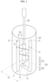
- FIG. 1 is a schematic view of an agitator according to embodiments of the present disclosure
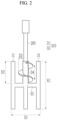
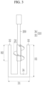
- FIG. 2 and FIG. 3 are views of a wing portion of the agitator of FIG. 1 .
- the agitation tank 100 may have a cylindrical shape to provide an agitation space therein, but the shape of the agitation tank 100 is not limited to the specific shape shown in FIG. 1 .
- the shape of the agitation tank 100 may be any shape in which an internal space may be formed so that each component of the wing portion (described later) is accommodated inside the agitation tank 100.
- a horizontal cross-sectional shape i.e., a cross-sectional shape in a horizontal plane
- the agitation tank 100 may have any suitable shape, such as a circular shape, an oval shape, a quadrangular shape, or a polygonal shape.
- the rotation wing 300 which may be connected (directly and/or indirectly) to the rotation shaft 200, is configured to rotate in the agitation tank 100 in response to rotation of the rotation shaft 200, e.g. about a rotation axis.
- the rotation shaft 200 may be at the center (or substantially the center) of the agitation tank 100, the present disclosure is not limited thereto. In one or more embodiments, the rotation shaft 200 may be eccentric relative to the center of the agitation tank 100.
- the rotation wing 300 may include a first wing portion 310 and a second wing portion 320.
- the pair of first wings 31 may be opposite to each other with the rotation shaft 200 therebetween (e.g., the pair of first wings 31 may be on opposite sides of the rotation shaft 200), and the pair of second wings 32 may be opposite to each other with the rotation shaft 200 therebetween (e.g., the pair of second wings 32 may be on opposite sides of the rotation shaft 200).
- the first wings 31 and the second wings 32 may be alternately arranged at a certain angle along a circumference of a cylindrical agitator.
- four wings may be arranged in an order of one of the first wings 31, one of the second wings 32, the other of the first wings 31, and the other of the second wings 32, each at an angle ⁇ of approximately 90 degrees with respect to the adjacent wings.
- the third wing 33 and the fourth wing 34 may be arranged lengthwise in a direction crossing the rotation axis of the rotation shaft 200.
- the third wing 33 may connect an intermediate portion of the first wing 31 to the rotation shaft 200, and the fourth wing 34 may connect one end of the second wing 32 to the rotation shaft 200.
- the fourth wing 34 may be divided around or cross the rotation shaft 200 to connect the rotation shaft 200 and the second wings 32, but the present disclosure is not limited thereto.
- the fourth wing 34 may cross an end portion (e.g., the lower end) of the rotation shaft 200 to connect end portions (e.g., lower ends) of the pair of second wings 32 opposite to each other with the rotation shafted 200 arranged therebetween.
- a width D1 of the first wing portion 310 may have a ratio of approximately 9/10 (i.e., 0.9) with respect to an internal diameter D2 of the agitation tank 100.
- the second wing portion 320 may have the spiral structure in which the band-shaped wing 42, which has a plate shape and a long length in one direction, is wound along the outer surface of the auxiliary rotation shaft 41.
- the auxiliary rotation shaft 41 may have a through hole through which the rotation shaft 200 passes. After the rotation shaft 200 is inserted into the through hole, the auxiliary rotation shaft 41 may be fixed to the rotation shaft 200 such that the auxiliary rotation shaft 41 and the rotation shaft 200 are configured to be rotated together in response to rotation of the rotation shaft 200, for example about the same rotation axis.
- the rotation shaft 200 and the auxiliary rotation shaft 41 may be connected by a screw coupling or any other suitable attachment mechanism or means.
- a height H2 of the second wing portion 320 may be greater than or equal to approximately 1/2 of a height H1 of the first wing portion 310.
- a width D3 of the band-shaped wing 42 measured from the outer surface of the auxiliary rotation shaft 41 may have a ratio in a range from approximately 4/10 (i.e., 0.4) to approximately 5/10 (i.e., 0.5) with respect to the width D1 of the first wing portion 310.
- the width D3 of the band-shaped wing 42 may not be a length of an inclined surface formed by the band-shaped wing 42 obliquely attached to the outer surface of the auxiliary rotation shaft 41, and may instead be a distance measured in a direction perpendicular to the outer surface of the auxiliary rotation shaft 41 and may be a width measured by a straight-line distance from the outer surface of the auxiliary rotation shaft 41 to an outer end of the band-shaped wing 42.
- the band-shaped wing 42 may have a pitch D4 in a range from approximately 0.4 to 0.5 with respect to the width D1 of the first wing portion 310.
- the pitch D4 may be a distance between adjacent portions of the band-shaped wing 41 protruding furthest outward from the auxiliary rotation shaft 41 along a same side of the auxiliary rotation shaft 41.
- the band-shaped wing 42 may be formed at a pitch D4 in a range from approximately 0.4 to approximately 0.5 with respect to the internal diameter of the agitation tank 100 along a length direction of the auxiliary rotation shaft 41.
- the pitch may be a distance between a central portion of a portion most protruding outward and a central portion of a portion most protruding outward.
- the first wing portion 310 having an anchor-type configuration and the second wing portion 320 having a spiral-type configuration are configured to simultaneously mix a slurry, such as an active material. This mixing, in the interior of the agitation tank 100, is beneficial.
- the slurry may tend move to an upper end portion along the rotation shaft 200, and the slurry may be separated at an upper end portion of the first wing portion 310 so that particles included in the slurry do not disperse. If the slurry is separated, the particles may not be uniformly mixed, and sizes of the particles in the slurry may increase so that the viscosity of the slurry is greater than desired.
- the second wing portion 320 is included such that a phenomenon in which the slurry moves to an upper end portion and is separated may be mitigated against.
- the slurry may be uniformly (or substantially uniformly) mixed by the agitator.
- the direction of rotation of the rotation shaft can be chosen, taking account of a direction of the spiral, for facilitating this mitigation of the slurry movement.
- the second wing portion 320 may increase a downward flow of the slurry in a central portion of the agitator (e.g., the second wing portion 320 may increase a downward flow of the slurry from an upper end portion that is a gas-liquid boundary to a bottom surface of the agitation tank 100).
- the slurry remaining at the gas-liquid boundary may be forcibly moved to a middle portion and a lower portion of the agitator tank 100 so that a material included in the slurry is uniformly (or substantially uniformly) mixed.
- the height H2 of the second wing portion 320 may affect a flow of the slurry inside the first wing portion 310, and may have a greater influence on the internal downward flow. In some embodiments, as the height H2 of the second wing portion 320 increases, the downward flow of the slurry in the central portion from the upper end portion that is the gas-liquid boundary to the bottom surface of the agitation tank 100 may become stronger. Thus, the slurry may be uniformly (or substantially uniformly) mixed by adjusting (e.g., increasing) the height H2 of the second wing portion 320.
Landscapes
- Chemical & Material Sciences (AREA)
- Chemical Kinetics & Catalysis (AREA)
- Engineering & Computer Science (AREA)
- Manufacturing & Machinery (AREA)
- Electrochemistry (AREA)
- General Chemical & Material Sciences (AREA)
- Dispersion Chemistry (AREA)
- Mixers Of The Rotary Stirring Type (AREA)
Abstract
An agitator according to embodiments of the present disclosure includes: an agitation tank (100); a rotation shaft (200) that is installed to rotate within the agitation tank; a first wing portion (310) that is connected to the rotation shaft and includes a plurality of wings (31,32) parallel to the rotation shaft; and a second wing portion (320) that is connected to the rotation shaft and includes a band-shaped wing (42) forming a spiral, i.e. screw thread, along the rotation shaft.
Description
- The present disclosure relates to an agitator, and more particularly, to an agitator for mixing a slurry for a rechargeable battery.
- A rechargeable battery includes a positive electrode, a negative electrode, and a separator. The positive electrode and the negative electrode include a substrate that is a thin metal plate and an active material layer on the substrate.
- The active material layer is formed by applying a slurry in which an active material, a binder, a conductive material, and the like that are suitable for positive and negative electrode characteristics are mixed.
- To reduce a defect rate of a process for manufacturing the electrode and to improve homogeneity of the process, flowability or a rheological property of the slurry is important, and the rheological property is affected by the material composition and the particle dispersion of the slurry.
- If the slurry is agitated, the slurry tends to move to an upper end portion that is a gas-liquid boundary. Thus, a phenomenon in which particles are separated occurs and quality of the slurry is thereby reduced.
- The present disclosure relates to various embodiments of an agitator configured to uniformly or substantially uniformly mix a slurry used in manufacturing a rechargeable battery by reducing a separation phenomenon of the slurry.
- An agitator according to embodiments of the present disclosure includes: an agitation tank; a rotation shaft accommodated and configured to rotate within the agitation tank; a first wing portion connected to the rotation shaft and including wings substantially parallel to the rotation shaft; and a second wing portion connected to the rotation shaft and including a band-shaped wing forming a spiral (i.e. screw thread) along the rotation shaft.
- The first wing portion may include: a pair of first wings and a pair of second wings that are substantially parallel to the rotation shaft; a third wing that connects the first wing and the rotation shaft; and a fourth wing that connects the second wing and the rotation shaft.
- The second wing portion may further include an auxiliary rotation shaft that has a through hole and is fixed to the rotation shaft inserted into the through hole. The band-shaped wing may surround an outer surface of the auxiliary rotation shaft.
- The auxiliary rotation shaft may extend along a length direction of the rotation shaft, and the third wing may be below the auxiliary rotation shaft.
- The third wing may be at an intermediate portion of the first wing.
- A ratio of pitch of the spiral to a width of the first wing portion may be in a range from (approximately) 0.4 to (approximately) 0.5.
- A ratio of a width of the band-shaped wing to a width of the first wing portion may be in a range from (approximately) 0.4 to (approximately) 0.5.
- A height of the second wing portion may be greater than or equal to 1/2 of a height of the first wing portion, or equal to approximately 1/2 of a height of the first wing portion.
- A ratio of a width of the first wing portion to an internal diameter of the agitation tank may be approximately 0.9.
- In embodiments of the present disclosure, an agitator capable of preparing a slurry for a rechargeable battery in which particles are uniformly or substantially uniformly mixed by suppressing an upper movement of the slurry may be manufactured.
- At least some of the above and other features of the invention are set out in the claims.
-
-
FIG. 1 is a schematic view of an agitator according to embodiments of the present disclosure. -
FIG. 2 andFIG. 3 are views for describing a wing portion of the agitator ofFIG. 1 . - Embodiments of the present disclosure will be described more fully hereinafter with reference to the accompanying drawings so that those skilled in the art easily implement the embodiments. The present disclosure may be modified in various different ways, all without departing from the scope of the present disclosure.
- Because sizes and thicknesses of constituent members shown in the drawings are arbitrarily given for better understanding and ease of description, the present disclosure is not limited to the illustrated sizes and thicknesses.
- In the drawings, the thickness of layers, films, panels, regions, etc., is exaggerated for clarity. In the drawings, for better understanding and ease of description, thicknesses of some layers and areas are exaggeratedly displayed. It will be understood that when an element such as a layer, film, region, area, or substrate is referred to as being "on" or "above" another element, it may be directly on the other element or intervening elements may also be present.
- In addition, unless explicitly described to the contrary, the word "comprise", and variations such as "comprises" or "comprising", will be understood to imply the inclusion of stated elements but not the exclusion of any other elements.
-
FIG. 1 is a schematic view of an agitator according to embodiments of the present disclosure, andFIG. 2 andFIG. 3 are views of a wing portion of the agitator ofFIG. 1 . - As shown in
FIGS. 1 to 3 , the agitator according to the embodiments of the present disclosure may include anagitation tank 100, a rotation shaft 200 (e.g., a rod), and arotation wing 300. Therotation wing 300 may be coupled (directly and/or indirectly) to therotation shaft 200. - The
agitation tank 100 may have a cylindrical shape to provide an agitation space therein, but the shape of theagitation tank 100 is not limited to the specific shape shown inFIG. 1 . The shape of theagitation tank 100 may be any shape in which an internal space may be formed so that each component of the wing portion (described later) is accommodated inside theagitation tank 100. In one or more embodiments, a horizontal cross-sectional shape (i.e., a cross-sectional shape in a horizontal plane) of theagitation tank 100 may have any suitable shape, such as a circular shape, an oval shape, a quadrangular shape, or a polygonal shape. - The
rotation wing 300, which may be connected (directly and/or indirectly) to therotation shaft 200, is configured to rotate in theagitation tank 100 in response to rotation of therotation shaft 200, e.g. about a rotation axis. - The
rotation shaft 200 may be at a center (or substantially a center) of the agitation tank 100 (e.g., therotation shaft 200 may extend along or substantially along an imaginary axial centerline of the agitation tank 100 - defining the rotation axis). Therotation shaft 200 may be configured rotate within theagitation tank 100 together with therotation wing 300 to agitate a fluid in theagitation tank 100. - Although in one or more embodiments the
rotation shaft 200 may be at the center (or substantially the center) of theagitation tank 100, the present disclosure is not limited thereto. In one or more embodiments, therotation shaft 200 may be eccentric relative to the center of theagitation tank 100. - The
rotation wing 300 may include afirst wing portion 310 and asecond wing portion 320. - The
first wing portion 310 may include a pair offirst wings 31 and a pair ofsecond wings 32 that are directly connected to therotation shaft 200, are separated from therotation shaft 200 by a predetermined distance, and are parallel (or substantially parallel) to therotation shaft 200. Thefirst wing portion 310 also includes athird wing 33 connecting the pair offirst wings 31 to therotation shaft 200, and afourth wing 34 connecting the pair ofsecond wings 32 to therotation shaft 200. - The pair of
first wings 31 may be opposite to each other with therotation shaft 200 therebetween (e.g., the pair offirst wings 31 may be on opposite sides of the rotation shaft 200), and the pair ofsecond wings 32 may be opposite to each other with therotation shaft 200 therebetween (e.g., the pair ofsecond wings 32 may be on opposite sides of the rotation shaft 200). In some embodiments, thefirst wings 31 and thesecond wings 32 may be alternately arranged at a certain angle along a circumference of a cylindrical agitator. In one or more embodiments, four wings may be arranged in an order of one of thefirst wings 31, one of thesecond wings 32, the other of thefirst wings 31, and the other of thesecond wings 32, each at an angle θ of approximately 90 degrees with respect to the adjacent wings. - The
third wing 33 and thefourth wing 34 may be arranged lengthwise in a direction crossing the rotation axis of therotation shaft 200. Thethird wing 33 may connect an intermediate portion of thefirst wing 31 to therotation shaft 200, and thefourth wing 34 may connect one end of thesecond wing 32 to therotation shaft 200. In one or more embodiments, thefourth wing 34 may be divided around or cross therotation shaft 200 to connect therotation shaft 200 and thesecond wings 32, but the present disclosure is not limited thereto. Thefourth wing 34 may cross an end portion (e.g., the lower end) of therotation shaft 200 to connect end portions (e.g., lower ends) of the pair ofsecond wings 32 opposite to each other with the rotation shafted 200 arranged therebetween. - A width D1 of the
first wing portion 310 may have a ratio of approximately 9/10 (i.e., 0.9) with respect to an internal diameter D2 of theagitation tank 100. - The
second wing portion 320 may include anauxiliary rotation shaft 41 and a band-shaped wing 42 on an outer surface of theauxiliary rotation shaft 41. Thesecond wing portion 320 may be above thethird wing 33 along a length direction of therotation shaft 200, and the band-shaped wing 42 may have a spiral or helical structure or configuration, e.g. defining a screw thread or spiral. - In one or more embodiments, the
second wing portion 320 may have the spiral structure in which the band-shaped wing 42, which has a plate shape and a long length in one direction, is wound along the outer surface of theauxiliary rotation shaft 41. Theauxiliary rotation shaft 41 may have a through hole through which the rotation shaft 200 passes. After therotation shaft 200 is inserted into the through hole, theauxiliary rotation shaft 41 may be fixed to therotation shaft 200 such that theauxiliary rotation shaft 41 and therotation shaft 200 are configured to be rotated together in response to rotation of therotation shaft 200, for example about the same rotation axis. Therotation shaft 200 and theauxiliary rotation shaft 41 may be connected by a screw coupling or any other suitable attachment mechanism or means. - The band-
shaped wing 42 may not be directly connected to an outer surface of therotation shaft 200, but may instead be directly connected to the outer surface of theauxiliary rotation shaft 41 through which therotation shaft 200 extends. - A height H2 of the
second wing portion 320 may be greater than or equal to approximately 1/2 of a height H1 of thefirst wing portion 310. A width D3 of the band-shapedwing 42 measured from the outer surface of theauxiliary rotation shaft 41 may have a ratio in a range from approximately 4/10 (i.e., 0.4) to approximately 5/10 (i.e., 0.5) with respect to the width D1 of thefirst wing portion 310. In one or more embodiments, the width D3 of the band-shapedwing 42 may not be a length of an inclined surface formed by the band-shapedwing 42 obliquely attached to the outer surface of theauxiliary rotation shaft 41, and may instead be a distance measured in a direction perpendicular to the outer surface of theauxiliary rotation shaft 41 and may be a width measured by a straight-line distance from the outer surface of theauxiliary rotation shaft 41 to an outer end of the band-shapedwing 42. - The band-shaped
wing 42 may have a pitch D4 in a range from approximately 0.4 to 0.5 with respect to the width D1 of thefirst wing portion 310. In one or more embodiments, the pitch D4 may be a distance between adjacent portions of the band-shapedwing 41 protruding furthest outward from theauxiliary rotation shaft 41 along a same side of theauxiliary rotation shaft 41. The band-shapedwing 42 may be formed at a pitch D4 in a range from approximately 0.4 to approximately 0.5 with respect to the internal diameter of theagitation tank 100 along a length direction of theauxiliary rotation shaft 41. For example, the pitch may be a distance between a central portion of a portion most protruding outward and a central portion of a portion most protruding outward. - In one or more embodiments of the present disclosure, the
first wing portion 310 having an anchor-type configuration and thesecond wing portion 320 having a spiral-type configuration are configured to simultaneously mix a slurry, such as an active material. This mixing, in the interior of theagitation tank 100, is beneficial. - If only the
first wing portion 310 were connected to the rotation shaft 200 (i.e., thesecond wing portion 320 was omitted), the slurry may tend move to an upper end portion along therotation shaft 200, and the slurry may be separated at an upper end portion of thefirst wing portion 310 so that particles included in the slurry do not disperse. If the slurry is separated, the particles may not be uniformly mixed, and sizes of the particles in the slurry may increase so that the viscosity of the slurry is greater than desired. - In the embodiments of the present disclosure, the
second wing portion 320 is included such that a phenomenon in which the slurry moves to an upper end portion and is separated may be mitigated against. Thus, the slurry may be uniformly (or substantially uniformly) mixed by the agitator. The direction of rotation of the rotation shaft can be chosen, taking account of a direction of the spiral, for facilitating this mitigation of the slurry movement. - In some embodiments, the
second wing portion 320 may increase a downward flow of the slurry in a central portion of the agitator (e.g., thesecond wing portion 320 may increase a downward flow of the slurry from an upper end portion that is a gas-liquid boundary to a bottom surface of the agitation tank 100). Thus, the slurry remaining at the gas-liquid boundary may be forcibly moved to a middle portion and a lower portion of theagitator tank 100 so that a material included in the slurry is uniformly (or substantially uniformly) mixed. - In one or more embodiments, the height H2 of the
second wing portion 320 may affect a flow of the slurry inside thefirst wing portion 310, and may have a greater influence on the internal downward flow. In some embodiments, as the height H2 of thesecond wing portion 320 increases, the downward flow of the slurry in the central portion from the upper end portion that is the gas-liquid boundary to the bottom surface of theagitation tank 100 may become stronger. Thus, the slurry may be uniformly (or substantially uniformly) mixed by adjusting (e.g., increasing) the height H2 of thesecond wing portion 320. - While this disclosure has been described in connection with what is presently considered to be practical embodiments, it is to be understood that the disclosure is not limited to the disclosed embodiments. On the contrary, it is intended to cover various modifications and equivalent arrangements included within the scope of the appended claims.
-
- 100: agitation tank
- 310: first wing portion
- 320: second wing portion
Claims (9)
- An agitator comprising:an agitation tank;a rotation shaft accommodated in the agitation tank and configured to rotate within the agitation tank;a first wing portion coupled to the rotation shaft, the first wing portion comprising a plurality of wings substantially parallel to the rotation shaft; anda second wing portion coupled to the rotation shaft, the second wing portion comprising a band-shaped wing forming a spiral along the rotation shaft.
- The agitator as claimed in claim 1, wherein the first wing portion comprises:a pair of first wings and a pair of second wings that are substantially parallel to the rotation shaft;a third wing connecting the pair of first wings and the rotation shaft; anda fourth wing connecting the pair of second wings and the rotation shaft.
- The agitator as claimed in claim 1 or claim 2, wherein the second wing portion further comprises an auxiliary rotation shaft having a through hole,wherein the rotation shaft extends into the through hole in the auxiliary rotation shaft and is fixed to the rotation shaft, andwherein the band-shaped wing surrounds an outer surface of the auxiliary rotation shaft.
- The agitator as claimed in claim 3, when dependent upon claim 2, wherein the auxiliary rotation shaft extends along a length direction of the rotation shaft, and wherein the third wing is below the auxiliary rotation shaft.
- The agitator as claimed in claim 4, wherein the third wing is coupled to an intermediate portion of the pair of first wings.
- The agitator as claimed in any one of the preceding claims, wherein a ratio of a pitch of the spiral to a width of the first wing portion is in a range from 0.4 to 0.5.
- The agitator as claimed in any one of the preceding claims, wherein a ratio of a width of the band-shaped wing to a width of the first wing portion is in a range from 0.4 to 0.5.
- The agitator as claimed in any one of the preceding claims, wherein a height of the second wing portion is greater than or equal to 1/2 of a height of the first wing portion.
- The agitator as claimed in any one of the preceding claims, wherein a ratio of a width of the first wing portion to an internal diameter of the agitation tank is approximately 0.9.
Applications Claiming Priority (1)
| Application Number | Priority Date | Filing Date | Title |
|---|---|---|---|
| KR1020240002486A KR20250107637A (en) | 2024-01-05 | 2024-01-05 | Agitator |
Publications (1)
| Publication Number | Publication Date |
|---|---|
| EP4582175A1 true EP4582175A1 (en) | 2025-07-09 |
Family
ID=93923034
Family Applications (1)
| Application Number | Title | Priority Date | Filing Date |
|---|---|---|---|
| EP24219502.2A Pending EP4582175A1 (en) | 2024-01-05 | 2024-12-12 | Agitator |
Country Status (4)
| Country | Link |
|---|---|
| US (1) | US20250222417A1 (en) |
| EP (1) | EP4582175A1 (en) |
| KR (1) | KR20250107637A (en) |
| CN (1) | CN120268271A (en) |
Citations (4)
| Publication number | Priority date | Publication date | Assignee | Title |
|---|---|---|---|---|
| CN106492665A (en) * | 2016-12-28 | 2017-03-15 | 河南微服网络科技有限公司 | A kind of Chemical Manufacture solid-liquid mixer with many material input pipes |
| CN108106367A (en) * | 2017-12-14 | 2018-06-01 | 攀枝花市德铭再生资源开发有限公司 | Stirring and drying device |
| CN109331691A (en) * | 2018-10-17 | 2019-02-15 | 徐州华奥纺织有限公司 | A kind of lacquer coating material agitator |
| CN112007536A (en) * | 2020-08-31 | 2020-12-01 | 安徽喜宝高分子材料有限公司 | Be used for real mineral varnish production to use high-efficient mixer |
-
2024
- 2024-01-05 KR KR1020240002486A patent/KR20250107637A/en active Pending
- 2024-09-26 US US18/897,900 patent/US20250222417A1/en active Pending
- 2024-12-06 CN CN202411787895.8A patent/CN120268271A/en active Pending
- 2024-12-12 EP EP24219502.2A patent/EP4582175A1/en active Pending
Patent Citations (4)
| Publication number | Priority date | Publication date | Assignee | Title |
|---|---|---|---|---|
| CN106492665A (en) * | 2016-12-28 | 2017-03-15 | 河南微服网络科技有限公司 | A kind of Chemical Manufacture solid-liquid mixer with many material input pipes |
| CN108106367A (en) * | 2017-12-14 | 2018-06-01 | 攀枝花市德铭再生资源开发有限公司 | Stirring and drying device |
| CN109331691A (en) * | 2018-10-17 | 2019-02-15 | 徐州华奥纺织有限公司 | A kind of lacquer coating material agitator |
| CN112007536A (en) * | 2020-08-31 | 2020-12-01 | 安徽喜宝高分子材料有限公司 | Be used for real mineral varnish production to use high-efficient mixer |
Also Published As
| Publication number | Publication date |
|---|---|
| KR20250107637A (en) | 2025-07-14 |
| US20250222417A1 (en) | 2025-07-10 |
| CN120268271A (en) | 2025-07-08 |
Similar Documents
| Publication | Publication Date | Title |
|---|---|---|
| DE69921875T2 (en) | Two-piece throttle body | |
| DE102019216077A1 (en) | ELECTRODE PLATE, BATTERY CONTAINING THE ELECTRODE PLATE, METHOD FOR PRODUCING THE ELECTRODE PLATE, METHOD FOR PRODUCING THE BATTERY CONTAINING THE ELECTRODE PLATE, AND NOZZLE HEAD | |
| EP4582175A1 (en) | Agitator | |
| EP3171970B1 (en) | Stirring member apparatus | |
| US8998482B2 (en) | Agitation apparatus | |
| DE102007000740A1 (en) | A spark plug for an internal combustion engine, which is designed to maintain a good ignitability of a fuel | |
| DE102008017045A1 (en) | Stirring vessel, stirring system and method for homogenizing molten glass | |
| DE112008000296T5 (en) | Mikrowellenrotationsdünnschichtkonzentrator | |
| DE60208393T2 (en) | Method for mounting a stirrer | |
| EP4210863A1 (en) | Stirring element device and method for producing a stirring element device | |
| DE112014002732T5 (en) | Liquid level indicator | |
| CN210729194U (en) | Powder slurrying device | |
| DE112021006094T5 (en) | Microfluidic chip with coaxially arranged finely tunable capillaries | |
| DE69600505T2 (en) | Internal mixer for rubber | |
| DE102015118328B4 (en) | fuel cell device | |
| WO2024146673A1 (en) | Apparatus for coating a sheet-like carrier material with a slurry | |
| DE212023000419U1 (en) | Battery, battery module and power-consuming device | |
| CN210880243U (en) | Concrete mixing mechanism | |
| EP4516389A1 (en) | A mixer and stirring device | |
| CN206483397U (en) | A kind of soft magnetic ferrite production stirring apparatus of pulp | |
| WO2021009019A1 (en) | Gas-inlet element for a cvd reactor | |
| DE202024105362U1 (en) | Jellyroll, battery cell, battery and power consumer | |
| US12087464B2 (en) | Method for manufacturing conductive paste and method for manufacturing multilayer ceramic electronic component | |
| DE112024001470T5 (en) | Kneading device | |
| CN218393404U (en) | Mixer and mixing system |
Legal Events
| Date | Code | Title | Description |
|---|---|---|---|
| PUAI | Public reference made under article 153(3) epc to a published international application that has entered the european phase |
Free format text: ORIGINAL CODE: 0009012 |
|
| STAA | Information on the status of an ep patent application or granted ep patent |
Free format text: STATUS: REQUEST FOR EXAMINATION WAS MADE |
|
| 17P | Request for examination filed |
Effective date: 20241212 |
|
| AK | Designated contracting states |
Kind code of ref document: A1 Designated state(s): AL AT BE BG CH CY CZ DE DK EE ES FI FR GB GR HR HU IE IS IT LI LT LU LV MC ME MK MT NL NO PL PT RO RS SE SI SK SM TR |