EP4582118A1 - Gasket retainer, gasket retainer set, and gasket container - Google Patents
Gasket retainer, gasket retainer set, and gasket container Download PDFInfo
- Publication number
- EP4582118A1 EP4582118A1 EP23891076.4A EP23891076A EP4582118A1 EP 4582118 A1 EP4582118 A1 EP 4582118A1 EP 23891076 A EP23891076 A EP 23891076A EP 4582118 A1 EP4582118 A1 EP 4582118A1
- Authority
- EP
- European Patent Office
- Prior art keywords
- gasket
- holding tool
- outer peripheral
- base plate
- distal
- Prior art date
- Legal status (The legal status is an assumption and is not a legal conclusion. Google has not performed a legal analysis and makes no representation as to the accuracy of the status listed.)
- Pending
Links
Images



Classifications
-
- A—HUMAN NECESSITIES
- A61—MEDICAL OR VETERINARY SCIENCE; HYGIENE
- A61M—DEVICES FOR INTRODUCING MEDIA INTO, OR ONTO, THE BODY; DEVICES FOR TRANSDUCING BODY MEDIA OR FOR TAKING MEDIA FROM THE BODY; DEVICES FOR PRODUCING OR ENDING SLEEP OR STUPOR
- A61M5/00—Devices for bringing media into the body in a subcutaneous, intra-vascular or intramuscular way; Accessories therefor, e.g. filling or cleaning devices, arm-rests
- A61M5/178—Syringes
- A61M5/31—Details
- A61M5/315—Pistons; Piston-rods; Guiding, blocking or restricting the movement of the rod or piston; Appliances on the rod for facilitating dosing ; Dosing mechanisms
- A61M5/31511—Piston or piston-rod constructions, e.g. connection of piston with piston-rod
- A61M5/31513—Piston constructions to improve sealing or sliding
-
- A—HUMAN NECESSITIES
- A61—MEDICAL OR VETERINARY SCIENCE; HYGIENE
- A61L—METHODS OR APPARATUS FOR STERILISING MATERIALS OR OBJECTS IN GENERAL; DISINFECTION, STERILISATION OR DEODORISATION OF AIR; CHEMICAL ASPECTS OF BANDAGES, DRESSINGS, ABSORBENT PADS OR SURGICAL ARTICLES; MATERIALS FOR BANDAGES, DRESSINGS, ABSORBENT PADS OR SURGICAL ARTICLES
- A61L2/00—Disinfection or sterilisation of materials or objects, in general; Accessories therefor
- A61L2/02—Disinfection or sterilisation of materials or objects, in general; Accessories therefor using physical processes
- A61L2/04—Heat
- A61L2/06—Hot gas
- A61L2/07—Steam
-
- A—HUMAN NECESSITIES
- A61—MEDICAL OR VETERINARY SCIENCE; HYGIENE
- A61M—DEVICES FOR INTRODUCING MEDIA INTO, OR ONTO, THE BODY; DEVICES FOR TRANSDUCING BODY MEDIA OR FOR TAKING MEDIA FROM THE BODY; DEVICES FOR PRODUCING OR ENDING SLEEP OR STUPOR
- A61M5/00—Devices for bringing media into the body in a subcutaneous, intra-vascular or intramuscular way; Accessories therefor, e.g. filling or cleaning devices, arm-rests
- A61M5/001—Apparatus specially adapted for cleaning or sterilising syringes or needles
-
- A—HUMAN NECESSITIES
- A61—MEDICAL OR VETERINARY SCIENCE; HYGIENE
- A61M—DEVICES FOR INTRODUCING MEDIA INTO, OR ONTO, THE BODY; DEVICES FOR TRANSDUCING BODY MEDIA OR FOR TAKING MEDIA FROM THE BODY; DEVICES FOR PRODUCING OR ENDING SLEEP OR STUPOR
- A61M5/00—Devices for bringing media into the body in a subcutaneous, intra-vascular or intramuscular way; Accessories therefor, e.g. filling or cleaning devices, arm-rests
- A61M5/002—Packages specially adapted therefor, e.g. for syringes or needles, kits for diabetics
-
- A—HUMAN NECESSITIES
- A61—MEDICAL OR VETERINARY SCIENCE; HYGIENE
- A61M—DEVICES FOR INTRODUCING MEDIA INTO, OR ONTO, THE BODY; DEVICES FOR TRANSDUCING BODY MEDIA OR FOR TAKING MEDIA FROM THE BODY; DEVICES FOR PRODUCING OR ENDING SLEEP OR STUPOR
- A61M5/00—Devices for bringing media into the body in a subcutaneous, intra-vascular or intramuscular way; Accessories therefor, e.g. filling or cleaning devices, arm-rests
- A61M5/178—Syringes
- A61M5/31—Details
- A61M5/315—Pistons; Piston-rods; Guiding, blocking or restricting the movement of the rod or piston; Appliances on the rod for facilitating dosing ; Dosing mechanisms
- A61M5/31511—Piston or piston-rod constructions, e.g. connection of piston with piston-rod
Definitions
- the present invention relates to a gasket holding tool, a gasket holding tool set, and a gasket housing body.
- the gasket can be held by the gasket holding tool while suppressing the distal-end-side protruding portion from being damaged by contact with the holding structure.
- a gasket housing body 10 is a medical device for simultaneously performing high-pressure steam sterilization (autoclave treatment) on a large number of gaskets 12.
- a syringe 300 which is a final product including the gasket 12, will be described.
- the gasket 12 includes a gasket body 14, a distal-end-side protruding portion 16 (sealing portion), and a proximal-end-side protruding portion 18.
- the gasket body 14 extends along the axial direction of the syringe body 302.
- the distal end surface 20 of the gasket body 14 seals the syringe chamber 314 from the proximal direction (see Fig. 8 ).
- the distal end surface 20 of the gasket body 14 is tapered in diameter in the distal direction.
- the length of the intermediate outer peripheral surface 24 along the axial direction of the gasket body 14 is 1/3 or more of the entire length of the gasket body 14 in the axial direction.
- the plunger 306 presses the gasket 12 in the distal direction.
- a distal end portion of the plunger 306 is connected to a connection hole 28 formed in the proximal end surface 26 of the gasket 12.
- the cap 308 seals the distal end opening of the nozzle 312.
- the gasket housing body 10 includes a plurality of gasket holding tool sets 30, a container 32, and a sealing member 34.
- the gasket holding tool 38 is integrally molded with a resin material.
- the gasket holding tool 38 includes a base plate 40, a large number of holding structures 42, and a plurality of leg portions 44.
- the base plate 40 is formed in a quadrangular shape.
- the base plate 40 has a pair of first sides 45a extending in parallel with each other and a pair of second sides 45b extending in parallel with each other.
- the through-hole 46 is a quadrangular hole.
- the two through-holes 46 are provided so as to be adjacent to the pair of second sides 45b of the base plate 40.
- the through-hole 46 is formed in a size that allows a finger of a human, a nail of a robot hand, or the like to pass through.
- the position, size, and shape of the through-hole 46 may be designed appropriately.
- the large number of holding structures 42 are arranged at intervals (at equal intervals) on the base plate 40.
- the large number of holding structures 42 are arranged in a line along the extending direction of the first side 45a of the base plate 40.
- the large number of holding structures 42 are arranged in a staggered manner (staggered) along the extending direction of the second side 45b.
- the holding structure 42 holds the gasket 12.
- the bulging portion 54 bulges radially inward from the inner peripheral surface of the cylindrical portion 52 and comes into contact with the outer peripheral surface 22 of the gasket body 14 to hold the gasket 12.
- a plurality of bulging portions 54 are provided at intervals in the circumferential direction of the cylindrical portion 52.
- six bulging portions 54 are provided at equal intervals in the circumferential direction of the cylindrical portion 52.
- the bulging portion 54 is located at an intermediate portion of the inner peripheral surface of the cylindrical portion 52 in the axial direction of the cylindrical portion 52.
- the lower end of the bulging portion 54 is located above the lower end of the cylindrical portion 52.
- the upper end of the bulging portion 54 is located below the upper end of the cylindrical portion 52.
- the gasket 12 is held in a predetermined posture by the bulging portion 54.
- the distal-end-side protruding portion 16 of the gasket 12 does not touch the bulging portion 54. Therefore, the distal-end-side protruding portion 16 is prevented from coming into contact with the holding structure 42 and being damaged (for example, peeling off the coating of the lubricant).
- the container leg portion 82 extends downward from the lower end of the support portion 80.
- the container leg portions 82 are provided in the same number as the support portions 80.
- the lower surface of the container leg portion 82 is at the same height position as the lower end of the peripheral wall 84.
- the lower surface of the container leg portion 82 comes into contact with an arrangement surface of a chamber (surface on which the gasket housing body 10 is arranged) of a high-pressure steam sterilization device (not illustrated).
- the support portion 80 and the container leg portion 82 receive the weight of the plurality of gasket holding tool sets 30.
- the peripheral wall 84 includes an upper peripheral wall 102 extending upward from the outer peripheral portion of the bottom wall 76 and a lower peripheral wall 104 extending downward from the outer peripheral portion of the bottom wall 76.
- the upper peripheral wall 102 extends in a quadrangular shape so as to surround the plurality of gasket holding tool sets 30 from the horizontal direction.
- the upper peripheral wall 102 forms the housing chamber 36.
- the upper peripheral wall 102 is bent so as to expand outward at a middle portion extending upward from the bottom wall 76. Accordingly, the rigidity of the upper peripheral wall 102 can be enhanced.
- An opening 106 is formed at an upper end of the upper peripheral wall 102.
- a plate-shaped rib 108 is provided on the inner surface of the peripheral wall 84 and the bottom surface 90 of the bottom wall 76 (see Fig. 2 ).
- the plurality of gasket holding tool sets 30 can be easily located. After the plurality of gasket holding tool sets 30 are arranged in the housing chamber 36 of the container 32, the opening 106 of the container 32 is sealed by the sealing member 34.
- the gasket housing body 10 is subjected to high-pressure steam sterilization in a chamber of a high-pressure steam sterilization device (not illustrated).
- the steam in the chamber passes through the sealing member 34, flows into the housing chamber 36 of the container 32, and comes into contact with the gasket 12.
- the steam flows through the gap 66 (see Fig. 5 ) between the bulging portions 54 adjacent to each other, the steam smoothly flows around the gasket 12.
- the water (liquid water) generated in the housing chamber 36 is dispersed and stored in the plurality of regions 92 of the bottom surface 90. That is, the water is not unevenly stored in one place of the bottom surface 90. Part of the water stored in each region 92 evaporates and returns to steam.
- Water (liquid water) generated in the inner hole 67 of the leg portion 44 is guided to the inner hole 67 of the leg portion 44 of the gasket holding tool 38 located at the lowermost position.
- the water in the inner hole 67 of the leg portion 44 is discharged to the outside of the support portion 80 via the notch 74 and the drain hole 100 and stored in the region 92 of the bottom surface 90.
- the outer tube 310 (barrel) of the syringe 300 is disposed below the gasket 12 of the gasket holding tool set 30 in a state where the proximal end opening of the outer tube 310 faces upward.
- the gasket 12 is plugged (for example, a vacuum plug) into the outer tube 310 by pressing the proximal end surface 26 of the gasket 12 from above toward the proximal end opening of the outer tube 310.
- the syringe 300 in which the gasket 12 is inserted into the outer tube 310 is manufactured.
- the bulging portion 54 is in contact with the first adjacent portion 25a of the outer peripheral surface 22 of the gasket body 14 adjacent in the proximal direction to the distal-end-side protruding portion 16.
- the distal end portion of the gasket 12 can be stably held by the bulging portion 54.
- the distal end portion of the gasket 12 can be more stably held by the bulging portion 54.
- the bulging portion 54 extends along the axial direction of the cylindrical portion 52 by a length of 1/2 or more of the entire length along the axial direction of the corresponding cylindrical portion 52.
- the gasket 12 can be stably held in the axial direction by the bulging portion 54.
- the leg portion 44 is formed in a tubular shape, and a notch 74 for discharging water inside the leg portion 44 is formed at a lower end portion of the leg portion 44.
- the water (liquid water) in the leg portion 44 can be discharged to the outside from the notch 74.
- the rigidity of the outer peripheral portion of the base plate 40 can be improved by the outer peripheral rib 48.
- a through-hole 46 for transportation is formed in a portion of the base plate 40 adjacent to the outer peripheral rib 48.
- the bottom surface rib 78 is formed such that each of the plurality of regions 92 has a polygonal shape in top view.
- the bottom surface rib 78 is formed such that each of the plurality of regions 92 has a hexagonal shape in top view.
- the rigidity of the bottom wall 76 can be more effectively improved by the bottom surface rib 78.
- the plurality of regions 92 can be arranged on the bottom surface 90 in a well-balanced manner.
- the bottom surface rib 78 can be arranged on the bottom surface 90 in a more balanced manner, it is possible to suppress the variation in the magnitude of the rigidity of the bottom wall 76. This makes it possible to further suppress thermal deformation of the bottom wall 76 (warpage of the bottom wall 76) at the time of high-pressure steam sterilization.
- the bottom wall 76 is located at a vertically intermediate portion of the peripheral wall 84.
- the rigidity of the peripheral wall 84 can be effectively improved by the bottom wall 76 as compared with the case where the bottom wall 76 is located at the lower end of the peripheral wall 84.
- the container 32 has a flange portion 86 extending outward from an upper end portion of the peripheral wall 84 and a flange rib 88 protruding in the vertical direction from the flange portion 86.
- the rigidity of the upper end portion of the peripheral wall 84 can be improved by the flange portion 86 and the flange rib 88.
- the container 32 has a support portion 80 protruding upward from the bottom wall 76.
- a support recess 94 into which the lower end of the leg portion 44 is insertable is provided at the upper end of the support portion 80.
- the weight of the gasket holding tool set 30 can be supported by the support portion 80 protruding from the bottom wall 76.
- the gasket holding tool 38 can be easily located with respect to the container 32.
- the lower end surface 70 of the leg portion 44 abuts on the bottom surface 96 of the support recess 94.
- a drain hole 100 for guiding the water discharged from the notch 74 to the outside of the support portion 80 is formed.
- the water (liquid water) in the leg portion 44 can be discharged through the notch 74 and the drain hole 100 at the time of high-pressure steam sterilization of the gasket 12.
- the container 32 has a container leg portion 82 that extends downward from the support portion 80 below the bottom wall 76 and receives a load acting on the support portion 80.
- the gasket holding tool 38 may have a holding structure 42a as in a modification illustrated in Fig. 9 instead of the holding structure 42.
- the same components as those of the above-described holding structure 42 are denoted by the same reference numerals, and the detailed description thereof will be omitted.
- the holding structure 42a according to the modification includes a cylindrical portion 52a and a bulging portion 54.
- the cylindrical portion 52a protrudes to both sides of the base plate 40. That is, the cylindrical portion 52a includes a portion protruding downward from the base plate 40 and a portion protruding upward from the base plate 40.
- the cylindrical portion may protrude from only one side of the base plate as in the present embodiment, or may protrude from both sides of the base plate as in the modification.
- the gasket holding tool 38 is used in both the step of sterilizing the gasket 12 with high-pressure steam (high-pressure steam sterilization step) and the step of inserting the gasket 12 into the outer tube 310 of the syringe 300 (plugging step).
- the gasket holding tool 38 may not be used in the high-pressure steam sterilization step, and may be used only in the plugging step.
- the high-pressure steam sterilization has been described as an example of the sterilization treatment, but gas sterilization may be performed instead of the high-pressure steam sterilization.
- gas sterilization examples include ethylene oxide and hydrogen peroxide.
Landscapes
- Health & Medical Sciences (AREA)
- Life Sciences & Earth Sciences (AREA)
- Veterinary Medicine (AREA)
- Public Health (AREA)
- General Health & Medical Sciences (AREA)
- Animal Behavior & Ethology (AREA)
- Anesthesiology (AREA)
- Hematology (AREA)
- Heart & Thoracic Surgery (AREA)
- Biomedical Technology (AREA)
- Engineering & Computer Science (AREA)
- Vascular Medicine (AREA)
- Epidemiology (AREA)
- Diabetes (AREA)
- Apparatus For Disinfection Or Sterilisation (AREA)
Abstract
Description
- The present invention relates to a gasket holding tool, a gasket holding tool set, and a gasket housing body.
- For example,
WO 2015/012206 discloses a gasket to be inserted into an outer tube of a syringe. The gasket includes a gasket body and an annular distal-end-side protruding portion that protrudes radially outward from an outer peripheral surface of the gasket body and is in liquid-tight contact with an inner peripheral surface of the outer tube. - Incidentally, for example, in a case where the gasket as described above is inserted into the cylindrical portion of the gasket holding tool and held before the gasket is plugged into the outer tube, there is a possibility that the distal-end-side protruding portion as the sealing portion comes into contact with the inner peripheral surface of the cylindrical portion and is damaged.
- An object of the present invention is to solve the problem described above.
-
- (1) A first aspect of the present disclosure is a gasket holding tool for holding a gasket to be inserted into an outer tube of a syringe, the gasket including: a gasket body; and an annular distal-end-side protruding portion that protrudes radially outward from a portion of an outer peripheral surface of the gasket body in a distal direction from a center in an axial direction of the gasket body and is in liquid-tight or gas-tight contact with an inner peripheral surface of the outer tube, the gasket holding tool including: a base plate; and a holding structure that is provided on the base plate to hold the gasket, in which the holding structure includes: a cylindrical portion that protrudes from the base plate in a thickness direction of the base plate and into which the gasket is insertable; and a bulging portion that bulges radially inward from an inner peripheral surface of the cylindrical portion and comes into contact with the outer peripheral surface of the gasket body to hold the gasket, the bulging portion is in contact with a portion of the outer peripheral surface of the gasket body in a proximal direction with respect to the distal-end-side protruding portion, and the holding structure is not in contact with the distal-end-side protruding portion in a holding state in which the gasket is held by the bulging portion.
According to such a configuration, by inserting the gasket into the cylindrical portion from the proximal direction of the gasket body, the gasket can be held by the bulging portion without the distal-end-side protruding portion touching the holding structure. In addition, the holding structure is not in contact with the distal-end-side protruding portion in the holding state of the gasket. As a result, the gasket can be held by the gasket holding tool while suppressing the distal-end-side protruding portion from being damaged by contact with the holding structure. - (2) In the gasket holding tool according to item (1), the bulging portion may be in contact with an adjacent portion of the outer peripheral surface of the gasket body adjacent to the distal-end-side protruding portion in a proximal direction.
According to such a configuration, the distal end portion of the gasket can be stably held by the bulging portion. - (3) In the gasket holding tool according to item (2), the adjacent portion may be located in a range of a length of 1/3 or less of an entire length of the gasket body along the axial direction from a distal end of the gasket toward a proximal direction.
According to such a configuration, the distal end portion of the gasket can be more stably held by the bulging portion. - (4) In the gasket holding tool according to any one of items (1) to (3), the cylindrical portion includes: a first opening located at one end of the cylindrical portion; and a second opening located at another end of the cylindrical portion, and in the holding state, a distal end of the gasket protrudes from the first opening to an outside of the cylindrical portion.
- (5) In the gasket holding tool according to any one of items (1) to (4), the bulging portion may extend along an axial direction of the cylindrical portion by a length of 1/2 or more of an entire length along the axial direction of the cylindrical portion.
According to such a configuration, the gasket can be stably held in the axial direction by the bulging portion. - (6) In the gasket holding tool according to any one of items (1) to (5), the gasket may have a proximal-end-side protruding portion that protrudes radially outward from the outer peripheral surface of the gasket body and be located in a proximal direction with respect to the center of the gasket body, and the bulging portion may be in contact with an intermediate outer peripheral surface between the distal-end-side protruding portion and the proximal-end-side protruding portion of the outer peripheral surface of the gasket body.
According to such a configuration, the gasket can be more stably held by the bulging portion. - (7) In the gasket holding tool according to any one of items (1) to (6), a plurality of the bulging portions may be arranged at intervals in a circumferential direction of the cylindrical portion, and a gap through which steam or gas can flow when high-pressure steam sterilization or gas sterilization is performed on the gasket in the holding state may be formed between the bulging portions adjacent to each other in a circumferential direction of the cylindrical portion.
According to such a configuration, the gasket held by the gasket holding tool can be efficiently sterilized with high-pressure steam or gas. In addition, the gasket can be stably held in the circumferential direction by the plurality of bulging portions. - (8) The gasket holding tool according to any one of items (1) to (7) includes a leg portion protruding downward from the base plate, in which a lower end of the leg portion may be located below a lower end of the gasket in the holding state.
According to such a configuration, in a case where the plurality of gasket holding tools are disposed in an overlapping manner, it is possible to prevent the adjacent gasket holding tools from coming into contact with the gasket. - (9) In the gasket holding tool according to item (8), a leg insertion recess into which a lower end of the leg portion is insertable may be provided at an upper end of the leg portion.
According to such a configuration, in a case where the plurality of gasket holding tools are disposed in an overlapping manner, the lower end portion of the leg portion can be easily located by being inserted into the leg insertion recess. - (10) In the gasket holding tool according to item (8) or (9), the leg portion may be formed in a tubular shape, and a notch for discharging water inside the leg portion may be formed at a lower end of the leg portion.
According to such a configuration, in a case where the gasket is sterilized with high-pressure steam, the water (liquid water) in the leg portion can be discharged to the outside from the notch. - (11) In the gasket holding tool according to any one of items (1) to (10), an outer peripheral rib protruding in a thickness direction of the base plate may be provided on an outer peripheral portion of the base plate.
According to such a configuration, the rigidity of the outer peripheral portion of the base plate can be improved by the outer peripheral rib. - (12) In the gasket holding tool according to item (11), a through-hole for transportation may be formed in a portion of the base plate adjacent to the outer peripheral rib.
According to such a configuration, it is possible to easily transport the gasket holding tool by inserting a human finger, a claw of a robot arm, or the like into the through-hole. Further, the periphery of the portion of the base plate where the through-hole is formed can be reinforced by the outer peripheral rib. - (13) In the gasket holding tool according to any one of items (1) to (12), the cylindrical portion may protrude only to one side of the base plate.
- (14) In the gasket holding tool according to any one of items (1) to (13), the cylindrical portion may protrude to both sides of the base plate.
According to such a configuration, compared to a case where the cylindrical portion protrudes only to one side of the base plate, rigidity of a portion of the base plate where the cylindrical portion is provided can be improved. - (15) A second aspect of the present disclosure is a gasket holding tool set including: a gasket holding tool according to any one of items (1) to (14); and the gasket.
- (16) A third aspect of the present disclosure is a gasket housing body including: a gasket holding tool set according to item (15); a container that has an opening opened upward and houses the gasket holding tool set; and a sealing member that seals the opening of the container, in which the sealing member is formed such that steam or gas for performing high-pressure steam sterilization or gas sterilization of the gasket can pass therethrough.
According to such a configuration, the gasket held by the gasket holding tool can be sterilized with high-pressure steam or gas. - (17) In the gasket housing body according to item (16), the container may include: a bottom wall having a bottom surface forming a housing chamber of the container; a peripheral wall provided on an outer peripheral portion of the bottom wall; and a bottom surface rib protruding upward from the bottom surface, and the bottom surface rib may be provided so as to partition the bottom surface into a plurality of regions.
According to such a configuration, the rigidity of the bottom wall can be improved by the bottom surface rib. Therefore, thermal deformation of the bottom wall (warpage of the bottom wall) during high-pressure steam sterilization can be suppressed. In addition, water (liquid water) generated at the time of high-pressure steam sterilization of the gasket can be dispersed and stored in the plurality of regions. That is, it is possible to suppress biased accumulation of water (liquid water) in the bottom surface. - (18) In the gasket housing body according to item (17), the bottom surface rib may be formed such that each of the plurality of regions has a polygonal shape in top view.
According to such a configuration, the rigidity of the bottom wall can be effectively improved by the bottom surface rib. - (19) In the gasket housing body according to item (18), the bottom surface rib may be formed such that each of the plurality of regions has a hexagonal shape in top view.
According to such a configuration, the rigidity of the bottom wall can be more effectively improved by the bottom surface rib. In addition, the plurality of regions can be arranged on the bottom surface in a well-balanced manner. - (20) In the gasket housing body according to item (19), the bottom surface rib may be formed such that one of the plurality of regions is located at a center of the bottom wall, and a center of the bottom wall may be located in the one region.
According to such a configuration, since the bottom surface rib can be arranged on the bottom surface in a more balanced manner, it is possible to suppress the variation in the magnitude of the rigidity of the bottom wall. This makes it possible to further suppress thermal deformation of the bottom wall (warpage of the bottom wall) at the time of high-pressure steam sterilization. - (21) In the gasket housing body according to any one of items (17) to (20), the bottom wall may be located at an intermediate portion of the peripheral wall in a vertical direction.
According to such a configuration, the rigidity of the peripheral wall can be effectively improved by the bottom wall as compared with the case where the bottom wall is located at the lower end of the peripheral wall. - (22) In the gasket housing body according to any one of items (17) to (21), the container may include: a flange portion extending outward from an upper end portion of the peripheral wall; and a flange rib protruding in a vertical direction from the flange portion.
According to such a configuration, the rigidity of the upper end portion of the peripheral wall can be improved by the flange portion and the flange rib. - (23) A fourth aspect of the present disclosure is a gasket housing body including: a gasket holding tool set including a gasket holding tool according to item (8) and the gasket; a container that has an opening opened upward and houses the gasket holding tool set; and a sealing member that seals the opening of the container, in which the sealing member is formed such that steam or gas for performing high-pressure steam sterilization or gas sterilization of the gasket can pass therethrough, the container includes: a bottom wall having a bottom surface forming a housing chamber of the container; a peripheral wall provided on an outer peripheral portion of the bottom wall; and a support portion protruding upward from the bottom wall, and a support recess into which a lower end portion of the leg portion is insertable is provided at an upper end portion of the support portion.
According to such a configuration, the weight of the gasket holding tool set can be supported by the support portion protruding from the bottom wall. By inserting the lower end portion of the leg portion of the gasket holding tool into the support recess, the gasket holding tool can be easily located with respect to the container. - (24) In the gasket housing body according to item (23), the leg portion may be formed in a tubular shape, a notch for discharging water inside the leg portion may be formed at a lower end portion of the leg portion, a lower end surface of the leg portion may abut on a bottom surface of the support recess, and a drain hole for guiding the water discharged from the notch to the outside of the support portion may be formed in a side wall forming the support recess.
According to such a configuration, the water (liquid water) in the leg portion can be discharged through the notch and the drain hole at the time of high-pressure steam sterilization of the gasket. - (25) In the gasket housing body according to item (23) or (24), the container may include a container leg portion that extends downward from the support portion below the bottom wall and receives a load acting on the support portion.
- According to such a configuration, since the load acting on the support portion can be received by the container leg portion, it is possible to suppress the support portion and the bottom wall from being deformed by the weight of the gasket holding tool set.
- According to the present invention, the gasket can be held by the gasket holding tool while suppressing the distal-end-side protruding portion from being damaged by contact with the holding structure.
-
-
Fig. 1 is a perspective view of a gasket housing body according to an embodiment of the present invention. -
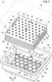
Fig. 2 is an exploded perspective view of the gasket housing body ofFig. 1 . -
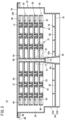
Fig. 3 is a longitudinal cross-sectional view taken along line III-III of the gasket housing body ofFig. 1 . -
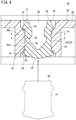
Fig. 4 is an enlarged view of the holding structure and the gasket ofFig. 3 . -
Fig. 5 is a transverse cross-sectional view taken along line V-V inFig. 4 . -
Fig. 6 is an enlarged view of the leg portion and the support portion ofFig. 3 . -
Fig. 7 is a plan view of the container ofFig. 2 . -
Fig. 8 is a longitudinal cross-sectional view of a syringe including the gasket ofFig. 3 . -
Fig. 9 is a cross-sectional view illustrating a holding structure according to a modification. - As illustrated in
Figs. 1 to 3 , agasket housing body 10 according to an embodiment of the present invention is a medical device for simultaneously performing high-pressure steam sterilization (autoclave treatment) on a large number ofgaskets 12. First, asyringe 300, which is a final product including thegasket 12, will be described. - As illustrated in
Fig. 8 , thesyringe 300 is configured as, for example, a prefilled syringe. However, as long as thesyringe 300 includes thegasket 12, the structure and use thereof are not limited. That is, thesyringe 300 may be a blood sampling syringe or the like. - The
syringe 300 includes asyringe body 302, adrug 304, agasket 12, aplunger 306, and acap 308. Thesyringe body 302 includes a cylindrical outer tube 310 (barrel) and anozzle 312 forming a distal end portion of theouter tube 310. Thegasket 12 is disposed inside theouter tube 310 so as to be slidable in the axial direction of thesyringe body 302. Asyringe chamber 314 filled with thedrug 304 is formed in the distal direction of thegasket 12 in theouter tube 310. - In
Figs. 4 and8 , thegasket 12 includes agasket body 14, a distal-end-side protruding portion 16 (sealing portion), and a proximal-end-side protruding portion 18. Thegasket body 14 extends along the axial direction of thesyringe body 302. Thedistal end surface 20 of thegasket body 14 seals thesyringe chamber 314 from the proximal direction (seeFig. 8 ). Thedistal end surface 20 of thegasket body 14 is tapered in diameter in the distal direction. - Each of the distal-end-
side protruding portion 16 and the proximal-end-side protruding portion 18 protrudes radially outward from an outerperipheral surface 22 of thegasket body 14 and annularly extends. The distal-end-side protruding portion 16 is provided at a distal end portion of the outerperipheral surface 22 of thegasket body 14. In other words, the distal-end-side protruding portion 16 is located in the distal direction from the center in the axial direction of thegasket body 14 and is not located in the proximal direction from the center in the axial direction of thegasket body 14. The distal-end-side protruding portion 16 is located in a range of 1/4 of the entire length in the axial direction of thegasket body 14 in the proximal direction from the distal end of thegasket body 14. - The distal-end-
side protruding portion 16 is formed to be narrowed radially outward (so that the width in the axial direction of thegasket body 14 is narrowed). The protruding end surface of the distal-end-side protruding portion 16 is formed in an arc shape when viewed from a direction orthogonal to the axial direction of the gasket body 14 (seeFig. 4 ). The outer surface of the distal-end-side protruding portion 16 is connected to thedistal end surface 20 of thegasket body 14 without a step. - As illustrated in
Fig. 8 , the distal-end-side protruding portion 16 is in liquid-tight or gas-tight contact with the inner surface of theouter tube 310. That is, thesyringe chamber 314 is kept liquid-tight or gas-tight by the distal-end-side protruding portion 16 of thegasket 12. A lubricant is applied to an outer surface of thegasket 12 including the distal-end-side protruding portion 16. Accordingly, thegasket 12 can smoothly slide on the inner surface of theouter tube 310 in the axial direction of thegasket body 14. - In
Figs. 4 and8 , the proximal-end-side protruding portion 18 is located in the proximal direction from the center in the axial direction of thegasket body 14 and is not located in the distal direction from the center in the axial direction of thegasket body 14. The proximal-end-side protruding portion 18 is located in the distal direction with respect to the proximal end of thegasket body 14. The proximal-end-side protruding portion 18 is formed to be narrowed radially outward (so that the width in the axial direction of thegasket body 14 is narrowed). - The protruding end surface of the proximal-end-
side protruding portion 18 is formed in an arc shape when viewed from a direction orthogonal to the axial direction of the gasket body 14 (seeFig. 4 ). InFig. 8 , the proximal-end-side protruding portion 18 is in contact with the inner surface of theouter tube 310. The proximal-end-side protruding portion 18 suppresses inclination of the axis of thegasket body 14 with respect to the axis of thesyringe body 302. - As illustrated in
Figs. 4 and8 , an intermediate outerperipheral surface 24 between the distal-end-side protruding portion 16 and the proximal-end-side protruding portion 18 in the outerperipheral surface 22 of thegasket body 14 is located radially inward of the distal-end-side protruding portion 16 and the proximal-end-side protruding portion 18. That is, thegasket 12 has a shape in which the intermediate portion in the axial direction of thegasket body 14 is recessed radially inward. The length of the intermediate outerperipheral surface 24 along the axial direction of the gasket body 14 (the interval between the distal-end-side protruding portion 16 and the proximal-end-side protruding portion 18) is 1/3 or more of the entire length of thegasket body 14 in the axial direction. - In
Fig. 8 , theplunger 306 presses thegasket 12 in the distal direction. A distal end portion of theplunger 306 is connected to aconnection hole 28 formed in theproximal end surface 26 of thegasket 12. Thecap 308 seals the distal end opening of thenozzle 312. - In
Figs. 1 to 3 , thegasket housing body 10 includes a plurality of gasket holding tool sets 30, acontainer 32, and a sealingmember 34. - As illustrated in
Figs. 2 and3 , the plurality of gasket holding tool sets 30 are housed in thehousing chamber 36 of thecontainer 32 in a state of being stacked on each other in the vertical direction. The gasket holding tool set 30 includes a large number ofgaskets 12 and agasket holding tool 38. Thegasket holding tool 38 holds a large number ofgaskets 12 of thesyringe 300. Before being held by thegasket holding tool 38, the outer surface of thegasket 12 including the distal-end-side protruding portion 16 is coated with a lubricant. - The
gasket holding tool 38 is integrally molded with a resin material. Thegasket holding tool 38 includes abase plate 40, a large number of holdingstructures 42, and a plurality ofleg portions 44. InFig. 2 , thebase plate 40 is formed in a quadrangular shape. Thebase plate 40 has a pair offirst sides 45a extending in parallel with each other and a pair ofsecond sides 45b extending in parallel with each other. - Two through-
holes 46 for transportation are formed in thebase plate 40. The through-hole 46 is a quadrangular hole. The two through-holes 46 are provided so as to be adjacent to the pair ofsecond sides 45b of thebase plate 40. The through-hole 46 is formed in a size that allows a finger of a human, a nail of a robot hand, or the like to pass through. The position, size, and shape of the through-hole 46 may be designed appropriately. - As illustrated in
Figs. 2 and3 , a reinforcing outerperipheral rib 48 protruding downward (in the thickness direction of the base plate 40) is provided on the outer peripheral portion of thebase plate 40. The outerperipheral rib 48 annularly extends along the outer peripheral portion of thebase plate 40. However, the outerperipheral rib 48 may not be integrally connected in an annular shape. The outerperipheral rib 48 may be intermittently provided along the outer peripheral portion of thebase plate 40. - The outer
peripheral rib 48 extends so as to cover the through-hole 46 from the outside. That is, the through-hole 46 is located adjacent to the inner side of the outerperipheral rib 48. The through-hole 46 is surrounded by the outerperipheral rib 48 and a U-shaped reinforcingrib 50. The reinforcingrib 50 protrudes downward from thebase plate 40 and is connected to the outerperipheral rib 48. - In
Fig. 2 , the large number of holdingstructures 42 are arranged at intervals (at equal intervals) on thebase plate 40. The large number of holdingstructures 42 are arranged in a line along the extending direction of thefirst side 45a of thebase plate 40. The large number of holdingstructures 42 are arranged in a staggered manner (staggered) along the extending direction of thesecond side 45b. The holdingstructure 42 holds thegasket 12. - As illustrated in
Figs. 4 and5 , the holdingstructure 42 includes acylindrical portion 52 and a bulgingportion 54. Thecylindrical portion 52 protrudes downward from thebase plate 40 and surrounds thegasket 12. Thecylindrical portion 52 is formed in a cylindrical shape. Thegasket 12 is inserted into thecylindrical portion 52. The inner diameter of thecylindrical portion 52 is larger than the maximum outer diameter of the gasket 12 (the outer diameter of the distal-end-side protruding portion 16). - In
Fig. 4 , thecylindrical portion 52 includes afirst opening 56 located at the lower end of thecylindrical portion 52 and asecond opening 58 located at the upper end of thecylindrical portion 52. Thesecond opening 58 is located at the same height position as the upper surface of thebase plate 40. That is, thecylindrical portion 52 does not protrude upward from the upper surface of thebase plate 40. The entire length of thecylindrical portion 52 is shorter than the entire length of thegasket 12. - The bulging
portion 54 bulges radially inward from the inner peripheral surface of thecylindrical portion 52 and comes into contact with the outerperipheral surface 22 of thegasket body 14 to hold thegasket 12. InFig. 5 , a plurality of bulgingportions 54 are provided at intervals in the circumferential direction of thecylindrical portion 52. In the present embodiment, six bulgingportions 54 are provided at equal intervals in the circumferential direction of thecylindrical portion 52. As illustrated inFig. 4 , the bulgingportion 54 is located at an intermediate portion of the inner peripheral surface of thecylindrical portion 52 in the axial direction of thecylindrical portion 52. The lower end of the bulgingportion 54 is located above the lower end of thecylindrical portion 52. The upper end of the bulgingportion 54 is located below the upper end of thecylindrical portion 52. - The bulging
portion 54 extends along the axial direction of thecylindrical portion 52 by a length of 1/2 or more of the entire length along the axial direction of thecylindrical portion 52. When viewed from the direction orthogonal to the axial direction of the cylindrical portion 52 (in the cross-sectional view ofFig. 4 ), the outer surface of thelower end portion 60 of the bulgingportion 54 protrudes in an arc shape toward the radially inner side of thecylindrical portion 52. The height of thelower end portion 60 of the bulging portion 54 (bulging length from the inner peripheral surface of the cylindrical portion 52) gradually decreases downward (first opening 56). - When viewed from the direction orthogonal to the axial direction of the cylindrical portion 52 (in the cross-sectional view of
Fig. 4 ), the outer surface of theupper end portion 62 of the bulgingportion 54 protrudes in an arc shape toward the radially inner side of thecylindrical portion 52. The height of theupper end portion 62 of the bulging portion 54 (bulging length from the inner peripheral surface of the cylindrical portion 52) gradually decreases upward (second opening 58). - An
intermediate portion 64 connecting thelower end portion 60 and theupper end portion 62 of the bulgingportion 54 extends at a constant height along the axial direction of thecylindrical portion 52. As illustrated inFig. 5 , the bulgingportion 54 protrudes radially inward in an arc shape as viewed in the axial direction of the cylindrical portion 52 (in the cross-sectional view ofFig. 5 ). - In a case where the
gasket 12 is attached to the holdingstructure 42, as illustrated inFig. 4 , thegasket 12 is inserted into thecylindrical portion 52 from thefirst opening 56 in a state where theproximal end surface 26 of thegasket body 14 faces thefirst opening 56 of thecylindrical portion 52. Then, the proximal-end-side protruding portion 18 gets over the bulgingportion 54, so that the bulgingportion 54 is located between the distal-end-side protruding portion 16 and the proximal-end-side protruding portion 18 of thegasket 12. That is, the bulgingportion 54 abuts on the intermediate outerperipheral surface 24 of thegasket body 14. In other words, the bulgingportion 54 presses the intermediate outerperipheral surface 24 of thegasket body 14 radially inward. - Specifically, the bulging
portion 54 abuts on the intermediate outerperipheral surface 24 from a firstadjacent portion 25a (adjacent portion) adjacent in the proximal direction to the distal-end-side protruding portion 16 in the intermediate outerperipheral surface 24 to a secondadjacent portion 25b adjacent in the distal direction to the proximal-end-side protruding portion 18 in the intermediate outerperipheral surface 24. The firstadjacent portion 25a is located in a range having a length of 1/3 or less of the entire length along the axial direction of thegasket body 14 from the distal end of thegasket 12 toward the proximal direction. Further, the firstadjacent portion 25a is preferably located in a range of 1/4 of the entire length along the axial direction of thegasket body 14 from the distal end of thegasket 12 toward the proximal direction. - Accordingly, the
gasket 12 is held in a predetermined posture by the bulgingportion 54. In a case where thegasket 12 is attached to the holdingstructure 42 in this manner, the distal-end-side protruding portion 16 of thegasket 12 does not touch the bulgingportion 54. Therefore, the distal-end-side protruding portion 16 is prevented from coming into contact with the holdingstructure 42 and being damaged (for example, peeling off the coating of the lubricant). - In the holding state (hereinafter, it may be simply referred to as a "holding state of the
gasket 12") in which thegasket 12 is held by the bulgingportion 54, the distal-end-side protruding portion 16 is away from (not in contact with) the holding structure 42 (thecylindrical portion 52 and the bulging portion 54). In the example ofFig. 4 , in the holding state of thegasket 12, the proximal-end-side protruding portion 18 is away from (not in contact with) the holding structure 42 (thecylindrical portion 52 and the bulging portion 54), but may be in contact with thecylindrical portion 52 or the bulgingportion 54. In the holding state of thegasket 12, the distal end (lower end) of thegasket 12 protrudes downward from thefirst opening 56 of thecylindrical portion 52. As illustrated inFig. 5 , agap 66 for allowing steam to flow at the time of high-pressure steam sterilization is formed between the bulgingportions 54 adjacent to each other in the holding state of thegasket 12. - The number, position, shape, and size of the bulging
portions 54 can be appropriately set. In particular, the number of bulgingportions 54 may be one or more (other than 6). In a case where the number of bulgingportions 54 is one, the bulgingportion 54 may extend in a range of 180° or more and less than 360° in the circumferential direction of thecylindrical portion 52 so as to form agap 66 for steam flow (for example, it may extend in a C shape or a U shape). In a case where only one bulgingportion 54 is provided, the bulgingportion 54 may extend spirally on the inner peripheral surface of thecylindrical portion 52 so as to form thegap 66 for steam flow. As the numbers of bulgingportions 54 increase, thegasket 12 can be stably held, but thegap 66 for the steam flow narrows, and it becomes difficult to remove thegasket 12 from thegasket holding tool 38. - In
Fig. 2 , theleg portions 44 are provided at a central portion and an outer peripheral portion of thebase plate 40. In the example ofFig. 2 , oneleg portion 44 is provided in the central portion of thebase plate 40 and six leg portions are provided in the outer peripheral portion of thebase plate 40. The number and positions of theleg portions 44 can be set as appropriate. - As illustrated in
Fig. 6 , theleg portion 44 protrudes downward from thebase plate 40. Theleg portion 44 is formed in a cylindrical shape. That is, theleg portion 44 has aninner hole 67 penetrating in the vertical direction. The outer peripheral surface of theleg portion 44 is tapered in diameter toward the lower side (protruding direction). As illustrated inFig. 3 , the lower end of theleg portion 44 is located below the lower end of thecylindrical portion 52. In other words, the lower end of theleg portion 44 is located below the lower end (distal end) of thegasket 12 in the holding state of thegasket 12. - In
Fig. 6 , aleg insertion recess 68 into which the lower end of theleg portion 44 is insertable is provided at the upper end of theleg portion 44. Theleg insertion recess 68 is a circular recess. Theinner hole 67 of theleg portion 44 is opened in abottom surface 72 of theleg insertion recess 68. That is, thebottom surface 72 of theleg insertion recess 68 extends in an annular shape. With thegasket holding tool 38 stacked in the vertical direction, alower end surface 70 of theleg portion 44 abuts on thebottom surface 72 of theleg insertion recess 68. The plurality ofgasket holding tools 38 are located in the horizontal direction by inserting theleg portion 44 into theleg insertion recess 68. - Two
notches 74 for discharging water (liquid water) in theinner hole 67 of theleg portion 44 are formed at the lower end of theleg portion 44. The twonotches 74 are located at positions shifted by 180° in the circumferential direction of theleg portion 44. The number, position, size, and shape of thenotches 74 may be designed appropriately. - As illustrated in
Figs. 2 and3 , thecontainer 32 is integrally molded with a resin material. Thecontainer 32 has ahousing chamber 36 that houses the plurality of gasket holding tool sets 30. - The
container 32 includes abottom wall 76, abottom surface rib 78, asupport portion 80, a container leg portion 82 (seeFig. 3 ), aperipheral wall 84, aflange portion 86, and aflange rib 88. InFig. 3 , thebottom wall 76 is formed in a plate shape and is connected to an intermediate portion in the height direction of theperipheral wall 84. Thebottom wall 76 is located between the center of theperipheral wall 84 in the vertical direction (height direction) and the lower end of theperipheral wall 84. Thebottom wall 76 has abottom surface 90 forming thehousing chamber 36. - The
bottom surface rib 78 protrudes upward from thebottom surface 90 of thebottom wall 76. InFigs. 2 ,3 , and7 , thebottom surface rib 78 is provided so as to partition thebottom surface 90 into a plurality ofregions 92. Eachregion 92 can store water generated during high-pressure steam sterilization. - As illustrated in
Figs. 2 and7 , thebottom surface rib 78 is formed such that eachregion 92 has a polygonal shape in top view. Specifically, thebottom surface rib 78 is formed such that eachregion 92 has a hexagonal shape in top view. In other words, thebottom surface rib 78 has a honeycomb structure in top view. - The size and shape of each
region 92, and the number ofregions 92 formed by thebottom surface rib 78 can be appropriately set. Thebottom surface rib 78 may be formed such that eachregion 92 has a triangular shape, a quadrangular shape, or a pentagonal shape. - As illustrated in
Fig. 7 , thebottom surface rib 78 is formed such that one region 92 (central region 92a) of the plurality ofregions 92 is located at the center of thebottom wall 76. A center P of thebottom wall 76 is located in thecentral region 92a. Specifically, the center P of thebottom wall 76 is located at the central portion of thehexagonal region 92. In other words, the center P of thebottom wall 76 is located at the center of thecentral region 92a or in the vicinity of the center. - As illustrated in
Figs. 2 and3 , thesupport portion 80 protrudes upward from thebottom wall 76 to support portion theleg portion 44 of thegasket holding tool 38. Asmany support portions 80 as theleg portions 44 of thegasket holding tool 38 are provided (seeFig. 2 ). - In
Figs. 2 ,6 , and7 , asupport recess 94 into which the lower end of theleg portion 44 is insertable is provided at the upper end of thesupport portion 80. Thelower end surface 70 of theleg portion 44 abuts on abottom surface 96 of the support recess 94 (seeFig. 6 ). In aside wall 98 forming thesupport recess 94, four drain holes 100 (drain grooves) for guiding water (liquid water) discharged from thenotch 74 to the outside of thesupport portion 80 are formed. The fourdrain holes 100 are provided at equal intervals (90° intervals) in the circumferential direction of thesupport portion 80. - As illustrated in
Fig. 3 , thecontainer leg portion 82 extends downward from the lower end of thesupport portion 80. Thecontainer leg portions 82 are provided in the same number as thesupport portions 80. The lower surface of thecontainer leg portion 82 is at the same height position as the lower end of theperipheral wall 84. The lower surface of thecontainer leg portion 82 comes into contact with an arrangement surface of a chamber (surface on which thegasket housing body 10 is arranged) of a high-pressure steam sterilization device (not illustrated). Thesupport portion 80 and thecontainer leg portion 82 receive the weight of the plurality of gasket holding tool sets 30. - In
Figs. 2 and3 , theperipheral wall 84 includes an upperperipheral wall 102 extending upward from the outer peripheral portion of thebottom wall 76 and a lowerperipheral wall 104 extending downward from the outer peripheral portion of thebottom wall 76. The upperperipheral wall 102 extends in a quadrangular shape so as to surround the plurality of gasket holding tool sets 30 from the horizontal direction. The upperperipheral wall 102 forms thehousing chamber 36. The upperperipheral wall 102 is bent so as to expand outward at a middle portion extending upward from thebottom wall 76. Accordingly, the rigidity of the upperperipheral wall 102 can be enhanced. Anopening 106 is formed at an upper end of the upperperipheral wall 102. A plate-shapedrib 108 is provided on the inner surface of theperipheral wall 84 and thebottom surface 90 of the bottom wall 76 (seeFig. 2 ). - The
flange portion 86 extends outward from the upper end of the upperperipheral wall 102. Theflange portion 86 extends annularly and is formed in a plate shape. The sealingmember 34 is fixed to the upper surface of theflange portion 86. Theflange rib 88 protrudes downward from the extending end of theflange portion 86. Theflange rib 88 reinforces theflange portion 86. Theflange rib 88 extends annularly so as to surround theflange portion 86. Theflange rib 88 only needs to protrude in at least one of the vertical directions from theflange portion 86. - The sealing
member 34 seals theopening 106 of thecontainer 32. The sealingmember 34 is formed to allow vapor to pass therethrough. - In the present embodiment, as illustrated in
Fig. 3 , the plurality of gasket holding tool sets 30 are arranged on thesupport portion 80 in a state of being overlapped with each other. At this time, the lower end of theleg portion 44 of thegasket holding tool 38 located at the lowermost position is inserted into thesupport recess 94 of the support portion 80 (seeFig. 6 ). Therefore, thegasket holding tool 38 can be easily located with respect to thecontainer 32. - Further, the lower end portion of the
leg portion 44 of thegasket holding tool 38 placed on the lowermostgasket holding tool 38 is inserted into theleg insertion recess 68 of thegasket holding tool 38 adjacent below (seeFig. 6 ). Thus, the plurality of gasket holding tool sets 30 can be easily located. After the plurality of gasket holding tool sets 30 are arranged in thehousing chamber 36 of thecontainer 32, theopening 106 of thecontainer 32 is sealed by the sealingmember 34. - The
gasket housing body 10 is subjected to high-pressure steam sterilization in a chamber of a high-pressure steam sterilization device (not illustrated). The steam in the chamber passes through the sealingmember 34, flows into thehousing chamber 36 of thecontainer 32, and comes into contact with thegasket 12. At this time, since the steam flows through the gap 66 (seeFig. 5 ) between the bulgingportions 54 adjacent to each other, the steam smoothly flows around thegasket 12. The water (liquid water) generated in thehousing chamber 36 is dispersed and stored in the plurality ofregions 92 of thebottom surface 90. That is, the water is not unevenly stored in one place of thebottom surface 90. Part of the water stored in eachregion 92 evaporates and returns to steam. - Water (liquid water) generated in the
inner hole 67 of theleg portion 44 is guided to theinner hole 67 of theleg portion 44 of thegasket holding tool 38 located at the lowermost position. The water in theinner hole 67 of theleg portion 44 is discharged to the outside of thesupport portion 80 via thenotch 74 and thedrain hole 100 and stored in theregion 92 of thebottom surface 90. - After the high-pressure steam sterilization is performed, the sealing
member 34 is opened. Then, a human finger or a claw of a robot arm is inserted into the through-hole 46 of thegasket holding tool 38, and the gasket holding tool set 30 is transported to a plugging device (not illustrated). - Thereafter, for example, the outer tube 310 (barrel) of the
syringe 300 is disposed below thegasket 12 of the gasket holding tool set 30 in a state where the proximal end opening of theouter tube 310 faces upward. Then, thegasket 12 is plugged (for example, a vacuum plug) into theouter tube 310 by pressing theproximal end surface 26 of thegasket 12 from above toward the proximal end opening of theouter tube 310. As a result, thesyringe 300 in which thegasket 12 is inserted into theouter tube 310 is manufactured. - The present embodiment has the following effects.
- According to the present embodiment, by inserting the
gasket 12 into thecylindrical portion 52 from the proximal direction of thegasket body 14, thegasket 12 can be held by the bulgingportion 54 without the distal-end-side protruding portion 16 touching the holdingstructure 42. In addition, the holdingstructure 42 is not in contact with the distal-end-side protruding portion 16 in the holding state of thegasket 12. As a result, thegasket 12 can be held by thegasket holding tool 38 while suppressing the distal-end-side protruding portion 16 from being damaged by being in contact with the holdingstructure 42. - The bulging
portion 54 is in contact with the firstadjacent portion 25a of the outerperipheral surface 22 of thegasket body 14 adjacent in the proximal direction to the distal-end-side protruding portion 16. - According to such a configuration, the distal end portion of the
gasket 12 can be stably held by the bulgingportion 54. - The first
adjacent portion 25a is located in a range having a length of 1/3 or less of the entire length along the axial direction of thegasket body 14 from the distal end of thegasket 12 toward the proximal direction. - According to such a configuration, the distal end portion of the
gasket 12 can be more stably held by the bulgingportion 54. - The bulging
portion 54 extends along the axial direction of thecylindrical portion 52 by a length of 1/2 or more of the entire length along the axial direction of the correspondingcylindrical portion 52. - According to such a configuration, the
gasket 12 can be stably held in the axial direction by the bulgingportion 54. - The
gasket 12 has a proximal-end-side protruding portion 18 which protrudes radially outward from the outerperipheral surface 22 of thegasket body 14 and is located in the proximal direction with respect to the center of thegasket body 14. The bulgingportion 54 is in contact with an intermediate outerperipheral surface 24 between the distal-end-side protruding portion 16 and the proximal-end-side protruding portion 18 of the outerperipheral surface 22 of thegasket body 14. - According to such a configuration, the
gasket 12 can be more stably held by the bulgingportion 54. - The plurality of bulging
portions 54 are arranged at intervals in the circumferential direction of thecylindrical portion 52. Between the bulgingportions 54 adjacent to each other in the circumferential direction of thecylindrical portion 52, thegap 66 through which steam can flow in a holding state of thegasket 12 is formed. - According to such a configuration, the
gasket 12 held by thegasket holding tool 38 can be efficiently sterilized with high-pressure steam. In addition, thegasket 12 can be stably held in the circumferential direction by the plurality of bulgingportions 54. - The
gasket holding tool 38 includes aleg portion 44 protruding downward from thebase plate 40. The lower end of theleg portion 44 is located below the lower end of thegasket 12 in the holding state. - According to such a configuration, in a case where the plurality of
gasket holding tools 38 are disposed in an overlapping manner, it is possible to prevent the adjacentgasket holding tools 38 from coming into contact with thegasket 12. - A
leg insertion recess 68 into which a lower end of theleg portion 44 is insertable is provided at an upper end of theleg portion 44. - According to such a configuration, in a case where the plurality of
gasket holding tools 38 are disposed in an overlapping manner, the lower end portion of theleg portion 44 can be easily located by being inserted into theleg insertion recess 68. - The
leg portion 44 is formed in a tubular shape, and anotch 74 for discharging water inside theleg portion 44 is formed at a lower end portion of theleg portion 44. - According to such a configuration, in a case where the
gasket 12 is sterilized with high-pressure steam, the water (liquid water) in theleg portion 44 can be discharged to the outside from thenotch 74. - An outer
peripheral rib 48 protruding in a thickness direction of thebase plate 40 is provided on an outer peripheral portion of thebase plate 40. - According to such a configuration, the rigidity of the outer peripheral portion of the
base plate 40 can be improved by the outerperipheral rib 48. - A through-
hole 46 for transportation is formed in a portion of thebase plate 40 adjacent to the outerperipheral rib 48. - According to such a configuration, it is possible to easily transport the
gasket holding tool 38 by inserting a human finger, a claw of a robot arm, or the like into the through-hole 46. Further, the periphery of the portion of thebase plate 40 where the through-hole 46 is formed can be reinforced by the outerperipheral rib 48. - In the
gasket housing body 10, thecontainer 32 includes abottom wall 76 having abottom surface 90 forming thehousing chamber 36 of thecontainer 32, aperipheral wall 84 provided on an outer peripheral portion of thebottom wall 76, and abottom surface rib 78 protruding upward from thebottom surface 90. Thebottom surface rib 78 is provided so as to partition thebottom surface 90 into a plurality ofregions 92. - According to such a configuration, the rigidity of the
bottom wall 76 can be improved by thebottom surface rib 78. Therefore, thermal deformation of the bottom wall 76 (warpage of the bottom wall 76) during high-pressure steam sterilization can be suppressed. In addition, water (liquid water) generated at the time of high-pressure steam sterilization of thegasket 12 can be dispersed and stored in the plurality ofregions 92. That is, it is possible to suppress biased accumulation of water (liquid water) in thebottom surface 90. - The
bottom surface rib 78 is formed such that each of the plurality ofregions 92 has a polygonal shape in top view. - According to such a configuration, the rigidity of the
bottom wall 76 can be effectively improved by thebottom surface rib 78. - The
bottom surface rib 78 is formed such that each of the plurality ofregions 92 has a hexagonal shape in top view. - According to such a configuration, the rigidity of the
bottom wall 76 can be more effectively improved by thebottom surface rib 78. In addition, the plurality ofregions 92 can be arranged on thebottom surface 90 in a well-balanced manner. - The
bottom surface rib 78 is formed such that one region 92 (central region 92a) of the plurality ofregions 92 is located at the center of thebottom wall 76. The center P of thebottom wall 76 is located in thecentral region 92a. - According to such a configuration, since the
bottom surface rib 78 can be arranged on thebottom surface 90 in a more balanced manner, it is possible to suppress the variation in the magnitude of the rigidity of thebottom wall 76. This makes it possible to further suppress thermal deformation of the bottom wall 76 (warpage of the bottom wall 76) at the time of high-pressure steam sterilization. - The
bottom wall 76 is located at a vertically intermediate portion of theperipheral wall 84. - According to such a configuration, the rigidity of the
peripheral wall 84 can be effectively improved by thebottom wall 76 as compared with the case where thebottom wall 76 is located at the lower end of theperipheral wall 84. - The
container 32 has aflange portion 86 extending outward from an upper end portion of theperipheral wall 84 and aflange rib 88 protruding in the vertical direction from theflange portion 86. - According to such a configuration, the rigidity of the upper end portion of the
peripheral wall 84 can be improved by theflange portion 86 and theflange rib 88. - The
container 32 has asupport portion 80 protruding upward from thebottom wall 76. Asupport recess 94 into which the lower end of theleg portion 44 is insertable is provided at the upper end of thesupport portion 80. - According to such a configuration, the weight of the gasket holding tool set 30 can be supported by the
support portion 80 protruding from thebottom wall 76. By inserting the lower end portion of theleg portion 44 of thegasket holding tool 38 into thesupport recess 94, thegasket holding tool 38 can be easily located with respect to thecontainer 32. - The
lower end surface 70 of theleg portion 44 abuts on thebottom surface 96 of thesupport recess 94. In theside wall 98 forming thesupport recess 94, adrain hole 100 for guiding the water discharged from thenotch 74 to the outside of thesupport portion 80 is formed. - According to such a configuration, the water (liquid water) in the
leg portion 44 can be discharged through thenotch 74 and thedrain hole 100 at the time of high-pressure steam sterilization of thegasket 12. - The
container 32 has acontainer leg portion 82 that extends downward from thesupport portion 80 below thebottom wall 76 and receives a load acting on thesupport portion 80. - According to such a configuration, since the load acting on the
support portion 80 can be received by thecontainer leg portion 82, it is possible to suppress thesupport portion 80 and thebottom wall 76 from being deformed by the weight of the gasket holding tool set 30. - In the present embodiment, the
gasket holding tool 38 may have a holdingstructure 42a as in a modification illustrated inFig. 9 instead of the holdingstructure 42. Further, in the present modification, the same components as those of the above-describedholding structure 42 are denoted by the same reference numerals, and the detailed description thereof will be omitted. As illustrated inFig. 9 , in thegasket holding tool 38, the holdingstructure 42a according to the modification includes acylindrical portion 52a and a bulgingportion 54. Thecylindrical portion 52a protrudes to both sides of thebase plate 40. That is, thecylindrical portion 52a includes a portion protruding downward from thebase plate 40 and a portion protruding upward from thebase plate 40. - According to such a configuration, compared to a case where the
cylindrical portion 52a protrudes only to one side of thebase plate 40, rigidity of a portion of thebase plate 40 where thecylindrical portion 52a is provided can be improved. - As described above, in the present invention, the cylindrical portion may protrude from only one side of the base plate as in the present embodiment, or may protrude from both sides of the base plate as in the modification.
- In the present embodiment, an example has been described in which the
gasket holding tool 38 is used in both the step of sterilizing thegasket 12 with high-pressure steam (high-pressure steam sterilization step) and the step of inserting thegasket 12 into theouter tube 310 of the syringe 300 (plugging step). However, thegasket holding tool 38 may not be used in the high-pressure steam sterilization step, and may be used only in the plugging step. - In the present embodiment, the high-pressure steam sterilization has been described as an example of the sterilization treatment, but gas sterilization may be performed instead of the high-pressure steam sterilization. Examples of the gas used for gas sterilization include ethylene oxide and hydrogen peroxide.
- Note that the present invention is not limited to the above disclosure, and various configurations can be adopted without departing from the gist of the present invention.
-
- 10
- gasket housing body
- 12
- gasket
- 14
- gasket body
- 16
- distal-end-side protruding portion
- 18
- proximal-end-side protruding portion
- 22
- outer peripheral surface
- 24
- intermediate outer peripheral surface
- 25a
- first adjacent portion (adjacent portion)
- 30
- gasket holding tool set
- 32
- container
- 34
- sealing member
- 36
- housing chamber
- 38
- gasket holding tool
- 40
- base plate
- 42, 42a
- holding structure
- 44
- leg portion
- 46
- through-hole
- 48
- outer peripheral rib
- 52, 52a
- cylindrical portion
- 54
- bulging portion
- 56
- first opening
- 58
- second opening
- 60
- lower end
- 62
- upper end
- 64
- intermediate portion
- 66
- gap
- 68
- leg insertion recess
- 70
- lower end surface
- 72
- bottom surface
- 74
- notch
- 76
- bottom wall
- 78
- bottom surface rib
- 80
- support portion
- 82
- container leg portion
- 84
- peripheral wall
- 86
- flange portion
- 88
- flange rib
- 90
- bottom surface of bottom wall
- 92
- region
- 92a
- central region
- 94
- support recess
- 96
- bottom surface of support recess
- 98
- side wall
- 100
- drain hole
- 106
- opening
- 300
- syringe
- 310
- outer tube
- P
- center
Claims (25)
- A gasket holding tool for holding a gasket to be inserted into an outer tube of a syringe,the gasket comprising:a gasket body; andan annular distal-end-side protruding portion that protrudes radially outward from a portion of an outer peripheral surface of the gasket body in a distal direction from a center in an axial direction of the gasket body and is in liquid-tight or gas-tight contact with an inner peripheral surface of the outer tube,the gasket holding tool comprising:a base plate; anda holding structure that is provided on the base plate to hold the gasket,whereinthe holding structure comprises:a cylindrical portion that protrudes from the base plate in a thickness direction of the base plate and into which the gasket is insertable; anda bulging portion that bulges radially inward from an inner peripheral surface of the cylindrical portion and comes into contact with the outer peripheral surface of the gasket body to hold the gasket,the bulging portion is in contact with a portion of the outer peripheral surface of the gasket body in a proximal direction with respect to the distal-end-side protruding portion, andthe holding structure is not in contact with the distal-end-side protruding portion in a holding state in which the gasket is held by the bulging portion.
- The gasket holding tool according to claim 1, wherein the bulging portion is in contact with an adjacent portion of the outer peripheral surface of the gasket body adjacent to the distal-end-side protruding portion in a proximal direction.
- The gasket holding tool according to claim 2, wherein the adjacent portion is located in a range of a length of 1/3 or less of an entire length of the gasket body along the axial direction from a distal end of the gasket toward a proximal direction.
- The gasket holding tool according to claim 1, whereinthe cylindrical portion comprises:a first opening located at one end of the cylindrical portion; anda second opening located at another end of the cylindrical portion, andin the holding state, a distal end of the gasket protrudes from the first opening to an outside of the cylindrical portion.
- The gasket holding tool according to claim 1, wherein the bulging portion extends along an axial direction of the cylindrical portion by a length of 1/2 or more of an entire length along the axial direction of the cylindrical portion.
- The gasket holding tool according to claim 1, whereinthe gasket has a proximal-end-side protruding portion that protrudes radially outward from the outer peripheral surface of the gasket body and is located in a proximal direction with respect to the center of the gasket body, andthe bulging portion is in contact with an intermediate outer peripheral surface between the distal-end-side protruding portion and the proximal-end-side protruding portion of the outer peripheral surface of the gasket body.
- The gasket holding tool according to claim 1, whereina plurality of the bulging portions are arranged at intervals in a circumferential direction of the cylindrical portion, anda gap through which steam or gas can flow when high-pressure steam sterilization or gas sterilization is performed on the gasket in the holding state is formed between the bulging portions adjacent to each other in a circumferential direction of the cylindrical portion.
- The gasket holding tool according to claim 1, comprising a leg portion protruding downward from the base plate,
wherein a lower end of the leg portion is located below a lower end of the gasket in the holding state. - The gasket holding tool according to claim 8, wherein a leg insertion recess into which a lower end of the leg portion is insertable is provided at an upper end of the leg portion.
- The gasket holding tool according to claim 8, whereinthe leg portion is formed in a tubular shape, anda notch for discharging water inside the leg portion is formed at a lower end of the leg portion.
- The gasket holding tool according to claim 1, wherein an outer peripheral rib protruding in a thickness direction of the base plate is provided on an outer peripheral portion of the base plate.
- The gasket holding tool according to claim 11, wherein a through-hole for transportation is formed in a portion of the base plate adjacent to the outer peripheral rib.
- The gasket holding tool according to claim 1, wherein the cylindrical portion protrudes only to one side of the base plate.
- The gasket holding tool according to claim 1, wherein the cylindrical portion protrudes to both sides of the base plate.
- A gasket holding tool set comprising:a gasket holding tool according to any one of claims 1 to 14; andthe gasket.
- A gasket housing body comprising:a gasket holding tool set according to claim 15;a container that has an opening opened upward and houses the gasket holding tool set; anda sealing member that seals the opening of the container,wherein the sealing member is formed such that steam or gas for performing high-pressure steam sterilization or gas sterilization of the gasket can pass therethrough.
- The gasket housing body according to claim 16, whereinthe container comprises:a bottom wall having a bottom surface forming a housing chamber of the container;a peripheral wall provided on an outer peripheral portion of the bottom wall; anda bottom surface rib protruding upward from the bottom surface, andthe bottom surface rib is provided so as to partition the bottom surface into a plurality of regions.
- The gasket housing body according to claim 17, wherein the bottom surface rib is formed such that each of the plurality of regions has a polygonal shape in top view.
- The gasket housing body according to claim 18, wherein the bottom surface rib is formed such that each of the plurality of regions has a hexagonal shape in top view.
- The gasket housing body according to claim 19, whereinthe bottom surface rib is formed such that one of the plurality of regions is located at a center of the bottom wall, anda center of the bottom wall is located in the one region.
- The gasket housing body according to claim 17, wherein the bottom wall is located at an intermediate portion of the peripheral wall in a vertical direction.
- The gasket housing body according to claim 17, wherein
the container comprises:a flange portion extending outward from an upper end portion of the peripheral wall; anda flange rib protruding in a vertical direction from the flange portion. - A gasket housing body comprising:a gasket holding tool set comprising a gasket holding tool according to claim 8 and the gasket;a container that has an opening opened upward and houses the gasket holding tool set; anda sealing member that seals the opening of the container,whereinthe sealing member is formed such that steam or gas for performing high-pressure steam sterilization or gas sterilization of the gasket can pass therethrough,the container comprises:a bottom wall having a bottom surface forming a housing chamber of the container;a peripheral wall provided on an outer peripheral portion of the bottom wall; anda support portion protruding upward from the bottom wall, anda support recess into which a lower end portion of the leg portion is insertable is provided at an upper end portion of the support portion.
- The gasket housing body according to claim 23, whereinthe leg portion is formed in a tubular shape,a notch for discharging water inside the leg portion is formed at a lower end portion of the leg portion,a lower end surface of the leg portion abuts on a bottom surface of the support recess, anda drain hole for guiding the water discharged from the notch to the outside of the support portion is formed in a side wall forming the support recess.
- The gasket housing body according to claim 23, wherein
the container comprises a container leg portion that extends downward from the support portion below the bottom wall and receives a load acting on the support portion.
Applications Claiming Priority (2)
| Application Number | Priority Date | Filing Date | Title |
|---|---|---|---|
| JP2022181790 | 2022-11-14 | ||
| PCT/JP2023/022587 WO2024105914A1 (en) | 2022-11-14 | 2023-06-19 | Gasket retainer, gasket retainer set, and gasket container |
Publications (2)
| Publication Number | Publication Date |
|---|---|
| EP4582118A1 true EP4582118A1 (en) | 2025-07-09 |
| EP4582118A4 EP4582118A4 (en) | 2025-12-10 |
Family
ID=91084397
Family Applications (1)
| Application Number | Title | Priority Date | Filing Date |
|---|---|---|---|
| EP23891076.4A Pending EP4582118A4 (en) | 2022-11-14 | 2023-06-19 | Gasket holder, gasket holder set and gasket container |
Country Status (4)
| Country | Link |
|---|---|
| US (1) | US20250262385A1 (en) |
| EP (1) | EP4582118A4 (en) |
| JP (1) | JPWO2024105914A1 (en) |
| WO (1) | WO2024105914A1 (en) |
Family Cites Families (6)
| Publication number | Priority date | Publication date | Assignee | Title |
|---|---|---|---|---|
| JP5107890B2 (en) * | 2006-02-28 | 2012-12-26 | 株式会社大協精工 | Piston nest for syringe |
| WO2013103079A1 (en) * | 2012-01-06 | 2013-07-11 | テルモ株式会社 | Gasket storage container |
| JPWO2015012206A1 (en) | 2013-07-22 | 2017-03-02 | ニプロ株式会社 | Gasket and plunger, syringe and prefilled syringe using the same |
| EP3357525B1 (en) * | 2015-09-29 | 2025-08-20 | Terumo Kabushiki Kaisha | Medical device packaging container, medical device package, and cylindrical outer package for prefilled syringe |
| JP6863606B2 (en) * | 2016-04-28 | 2021-04-21 | 株式会社大協精工 | container |
| JP6694900B2 (en) * | 2018-02-08 | 2020-05-20 | 株式会社大協精工 | Holding member and syringe piston packaging structure |
-
2023
- 2023-06-19 JP JP2024558635A patent/JPWO2024105914A1/ja active Pending
- 2023-06-19 EP EP23891076.4A patent/EP4582118A4/en active Pending
- 2023-06-19 WO PCT/JP2023/022587 patent/WO2024105914A1/en not_active Ceased
-
2025
- 2025-05-08 US US19/202,249 patent/US20250262385A1/en active Pending
Also Published As
| Publication number | Publication date |
|---|---|
| US20250262385A1 (en) | 2025-08-21 |
| JPWO2024105914A1 (en) | 2024-05-23 |
| EP4582118A4 (en) | 2025-12-10 |
| WO2024105914A1 (en) | 2024-05-23 |
Similar Documents
| Publication | Publication Date | Title |
|---|---|---|
| JP6694900B2 (en) | Holding member and syringe piston packaging structure | |
| US20120118777A1 (en) | Packaging Plate, Syringe-Holding Container, and Method of Manufacturing Combined Container-Syringe | |
| CN109071091B (en) | container | |
| JP7637732B2 (en) | Holding device configured to support a plurality of medical containers, such as syringes - Patents.com | |
| US20050256453A1 (en) | Syringe holder for balloon catheter and syringe set for balloon catheter | |
| US11161671B2 (en) | Medical device container | |
| JP7213871B2 (en) | A packaging device configured to support a medical container and a method for removing the medical container from said packaging device | |
| WO2018038078A1 (en) | Medical equipment package | |
| US20250262385A1 (en) | Gasket retainer, gasket retainer set, and gasket container | |
| EP4603114A1 (en) | Gasket holder, gasket holder set and gasket housing body | |
| US10899510B2 (en) | Vial assembly with cap with disinfectant and related methods | |
| US20010056265A1 (en) | Syringe for medical use | |
| WO2013084791A1 (en) | Gasket storage container | |
| CN117120121A (en) | Nesting sets for packaging plunger stops with integrated stacking features that ensure reliable alignment of a stack of nesting sets | |
| JP4449401B2 (en) | Prefilled syringe | |
| WO2025049894A1 (en) | Nest with enlarged interior chimney chamfer | |
| JP2025520958A (en) | Finger Grip | |
| JP6498492B2 (en) | Holder and sterilization method using the same | |
| JP7478555B2 (en) | Injection syringe barrel cap | |
| JP2006326191A (en) | Tray for syringes |
Legal Events
| Date | Code | Title | Description |
|---|---|---|---|
| STAA | Information on the status of an ep patent application or granted ep patent |
Free format text: STATUS: THE INTERNATIONAL PUBLICATION HAS BEEN MADE |
|
| PUAI | Public reference made under article 153(3) epc to a published international application that has entered the european phase |
Free format text: ORIGINAL CODE: 0009012 |
|
| STAA | Information on the status of an ep patent application or granted ep patent |
Free format text: STATUS: REQUEST FOR EXAMINATION WAS MADE |
|
| 17P | Request for examination filed |
Effective date: 20250403 |
|
| AK | Designated contracting states |
Kind code of ref document: A1 Designated state(s): AL AT BE BG CH CY CZ DE DK EE ES FI FR GB GR HR HU IE IS IT LI LT LU LV MC ME MK MT NL NO PL PT RO RS SE SI SK SM TR |
|
| A4 | Supplementary search report drawn up and despatched |
Effective date: 20251111 |
|
| RIC1 | Information provided on ipc code assigned before grant |
Ipc: A61M 5/00 20060101AFI20251105BHEP Ipc: A61L 2/07 20060101ALI20251105BHEP Ipc: A61M 5/315 20060101ALI20251105BHEP |
|
| DAV | Request for validation of the european patent (deleted) | ||
| DAX | Request for extension of the european patent (deleted) |