EP4581962A1 - Aerosol generating device and heater for aerosol generating device - Google Patents
Aerosol generating device and heater for aerosol generating device Download PDFInfo
- Publication number
- EP4581962A1 EP4581962A1 EP23876549.9A EP23876549A EP4581962A1 EP 4581962 A1 EP4581962 A1 EP 4581962A1 EP 23876549 A EP23876549 A EP 23876549A EP 4581962 A1 EP4581962 A1 EP 4581962A1
- Authority
- EP
- European Patent Office
- Prior art keywords
- aerosol generating
- heating part
- base
- annular element
- generating device
- Prior art date
- Legal status (The legal status is an assumption and is not a legal conclusion. Google has not performed a legal analysis and makes no representation as to the accuracy of the status listed.)
- Pending
Links
Images




Classifications
-
- A—HUMAN NECESSITIES
- A24—TOBACCO; CIGARS; CIGARETTES; SIMULATED SMOKING DEVICES; SMOKERS' REQUISITES
- A24F—SMOKERS' REQUISITES; MATCH BOXES; SIMULATED SMOKING DEVICES
- A24F40/00—Electrically operated smoking devices; Component parts thereof; Manufacture thereof; Maintenance or testing thereof; Charging means specially adapted therefor
- A24F40/40—Constructional details, e.g. connection of cartridges and battery parts
- A24F40/46—Shape or structure of electric heating means
-
- A—HUMAN NECESSITIES
- A24—TOBACCO; CIGARS; CIGARETTES; SIMULATED SMOKING DEVICES; SMOKERS' REQUISITES
- A24F—SMOKERS' REQUISITES; MATCH BOXES; SIMULATED SMOKING DEVICES
- A24F40/00—Electrically operated smoking devices; Component parts thereof; Manufacture thereof; Maintenance or testing thereof; Charging means specially adapted therefor
- A24F40/40—Constructional details, e.g. connection of cartridges and battery parts
-
- A—HUMAN NECESSITIES
- A24—TOBACCO; CIGARS; CIGARETTES; SIMULATED SMOKING DEVICES; SMOKERS' REQUISITES
- A24F—SMOKERS' REQUISITES; MATCH BOXES; SIMULATED SMOKING DEVICES
- A24F40/00—Electrically operated smoking devices; Component parts thereof; Manufacture thereof; Maintenance or testing thereof; Charging means specially adapted therefor
- A24F40/40—Constructional details, e.g. connection of cartridges and battery parts
- A24F40/42—Cartridges or containers for inhalable precursors
-
- A—HUMAN NECESSITIES
- A24—TOBACCO; CIGARS; CIGARETTES; SIMULATED SMOKING DEVICES; SMOKERS' REQUISITES
- A24F—SMOKERS' REQUISITES; MATCH BOXES; SIMULATED SMOKING DEVICES
- A24F40/00—Electrically operated smoking devices; Component parts thereof; Manufacture thereof; Maintenance or testing thereof; Charging means specially adapted therefor
- A24F40/70—Manufacture
-
- H—ELECTRICITY
- H05—ELECTRIC TECHNIQUES NOT OTHERWISE PROVIDED FOR
- H05B—ELECTRIC HEATING; ELECTRIC LIGHT SOURCES NOT OTHERWISE PROVIDED FOR; CIRCUIT ARRANGEMENTS FOR ELECTRIC LIGHT SOURCES, IN GENERAL
- H05B3/00—Ohmic-resistance heating
- H05B3/40—Heating elements having the shape of rods or tubes
- H05B3/42—Heating elements having the shape of rods or tubes non-flexible
- H05B3/44—Heating elements having the shape of rods or tubes non-flexible heating conductor arranged within rods or tubes of insulating material
-
- A—HUMAN NECESSITIES
- A24—TOBACCO; CIGARS; CIGARETTES; SIMULATED SMOKING DEVICES; SMOKERS' REQUISITES
- A24F—SMOKERS' REQUISITES; MATCH BOXES; SIMULATED SMOKING DEVICES
- A24F40/00—Electrically operated smoking devices; Component parts thereof; Manufacture thereof; Maintenance or testing thereof; Charging means specially adapted therefor
- A24F40/20—Devices using solid inhalable precursors
Definitions
- Embodiments of this application relate to the field of heat not burning aerosol generating technologies, and in particular, to an aerosol generating device and a heater for an aerosol generating device.
- Tobacco products (such as cigarettes and cigars) burn tobacco during use to produce tobacco smoke. Attempts are made to replace these tobacco-burning products by manufacturing products that release compounds without burning tobacco.
- An example of this type of products is a heating device that releases compounds by heating rather than burning materials.
- the materials may be tobacco or other non-tobacco products, where the non-tobacco products may or may not include nicotine.
- An existing heating device is inserted into the tobacco or other non-tobacco products through a resistive heater in a pin or needle shape for heating.
- An embodiment of this application provides an aerosol generating device, configured to heat an aerosol generating article to generate an aerosol, including:
- the heating part includes:
- the resistive heating coil is constructed to be a solenoid coil; and an extension size of a cross section of a wire material of the resistive heating coil in an axial direction is greater than an extension size of the cross section in a radial direction.
- the at least one annular element includes a metal or an alloy.
- a color of an outer surface of the at least one annular element is different from a color of the outer surface of the heating part.
- an extension size of the at least one annular element along the length direction of the heating part is 0.5 to 2 mm; and/or the extension dimension of the at least one annular element along the length direction of the heating part is less than an extension dimension of the base along the length direction of the heating part.
- a wall thickness of the annular element is 0.1 to 0.5 mm.
- the base is molded around a part of the heating part by using a moldable material, to couple the base to the heating part.
- the base includes an organic polymer.
- the base includes a first surface near or facing toward the free front end; and the at least one annular element is surrounded in the base, and is flush with the first surface.
- a distance between the at least one annular element and the tail end is greater than 0.5 mm.
- the base includes a first surface near or facing toward the free front end; and the at least one annular element partially extends from inside the base to outside the first surface.
- the conductive pin 321 and/or the conductive pin 322 have a diameter of about 0.1 to 0.5 mm; and the conductive pin 321 and/or the conductive pin 322 have a length of about 20 to 40 mm.
- the conductive pin 321 and/or the conductive pin 322 are made of a metal or an alloy with a low electrical resistance, for example, gold, silver, copper, or an alloy including gold, silver, or copper.
- the conductive pin 321 and/or the conductive pin 322 are a copper wire or a copper conductor having a plated layer such as a nickel layer on the surface.
- the heater 30 further includes: a base 34, at least partially surrounding or combined on the housing 31.
- the base 34 is basically arranged near the tail end 312, and the aerosol generating device clamps or holds the base 34, so that the heater 30 is stably mounted and fixed in the device.
- the base 34 basically avoids the resistive heating coil 32.
- the base 34 is basically located at an end of the resistance heating coil 32 near the tail end 312.
- the base 34 is closer to the tail end 312 than the resistive heating coil 32 is.
- the base 34 is arranged in a staggered manner relative to the resistive heating coil 32 along a length of the heater 30.
- a spacing between the base 34 and the resistive heating coil 32 along the length of the heater 30 is greater than 1 mm.
- the circuit 20 controls electricity provided by the battery core 21 to the heater 30, so that during use, a temperature of a part of the heating part and/or the housing 31 surrounded by the base 34 is less than 340°C.
- a temperature of a part of the heating part and/or the housing 31 surrounded by the base 34 is less than 320°C.
- the base 34 has a first side 3410 and a second side 3420 facing away from each other along a longitudinal direction.
- the first side 3410 faces toward or is near the free front end 311, and the second side 3420 faces toward or is near the tail end 312.
- a surface of the first side 3410 of the base 34 is flush with an inner bottom wall of the chamber that faces away from the opening 40.
- at least a part of the surface of the first side 3410 of the base 34 is exposed to the chamber.
- the base 34 includes:
- the outer side wall 341 and the inner side wall 342 are connected at the first side 3410 and are not connected at the second side 3420. Moreover, space in the cavity 343 is filled with air, to at least prevent heat of the housing 31 from being transferred to the outer side wall 341. Alternatively, the cavity 343 is configured to provide thermal insulation.
- the second side 3420 of the base 34 is basically flush with the tail end 312 of the housing 31.
- the connecting part 344 extends from the outer side wall 341 along the radial direction, the connecting part 344 is convex relative to the outer side wall 341, and the screw hole 345 runs through the connecting part 344 along a longitudinal direction of the base 34.
- the inner side wall 342 is slightly more convex than the outer side wall 341 on the second side 3420.
- the inner side wall 342 exceeds the outer side wall 341 by 0.4 mm on the second side 3420.
- the outer side wall 341 and the inner side wall 342 are flush at the second side 3420.
- the outer side wall 341 is slightly more convex than the inner side wall 342 on the second side 3420.
- FIG. 5 is a schematic diagram of a base 34c according to another variant embodiment.
- the base 34c includes: an outer side wall 341c, where a slot 3411c is defined on the outer side wall 341c, and the slot 3411c surrounds the outer side wall 341c and/or the base 34c in a peripheral direction.
- the aerosol generating device at least partially extends into the slot 3411c, to prevent the base 34c from moving in an axial direction.
- the aerosol generating device at least partially extends into the slot 3411c, so that the base 34 and/or the heater 30 can also be fastened in the aerosol generating device in a compressing manner.
- the base 34c further includes: a connecting part 344c extending from the outer side wall 341c to outside the second side 3420c; where there may be one or more connecting parts 344c, and a plurality of connecting parts 344c may alternatively be arranged around the outer side wall 341c in the peripheral direction.
- the connecting part 344c is convex relative to the second side 3420c along the longitudinal direction.
- the screw hole 345c in the connecting part 344c is screwed, to fasten the base 34c and/or the heater 30 in the aerosol generating device.
- the heater 30 further includes: at least one annular element, for example, an annular element 331 and an annular element 332, surrounding and combined on at least a part of the outer surface of the housing 31.
- the annular element 331 and the annular element 332 are arranged spaced apart along a longitudinal direction of the housing 31.
- the inner side wall 342 of the base 34 has a part 3421 that is snapped between the annular element 331 and the annular element 332. Further, after assembly, the part 3421 abuts against the annular element 331 and/or the annular element 332 along the longitudinal direction. Alternatively, the part 3421 is clamped by the annular element 331 and the annular element 332. Therefore, the annular element 331 and the annular element 332 are configured to prevent the base 34 from moving relative to the housing 31 along the longitudinal direction of the housing 31.
- the part 3421 of the base 34 is molded and the outer surface of the housing 31, or a gap or a spacing is less than 0.05 mm. If the part 3421 of the base 34 is separately prepared and then is riveted or mechanically fixed to the outer surface of the housing 31, there may be an assembly gap of 0.05 mm. In comparison, the part 3421 is more stably in contact with the annular element 331 and/or the annular element 332 according to the manner in this embodiment.
- the annular element 331 and the annular element 332 are combined on the outer surface of the housing 31 in a manner such as riveting.
- the annular element 331 and/or the annular element 332 have a color different from that of the outer surface of the housing 31.
- the housing 31 is made of stainless steel, and the outer surface of the housing 31 is of a silver color; and the annular element 331 and/or the annular element 332 are made of brass, and the annular element 331 and/or the annular element 332 are yellow.
- an equipment identifies and locates locations of the annular element 331 and/or the annular element 332, and then assembles and prepares the base 34 around the annular element 331 and/or the annular element 332.
- the base 34 completely surrounds the annular element 331 and/or the annular element 332.
- the annular element 331 and/or the annular element 332 do not extend out or are not exposed outside the base 34.
- the annular element 331 is closer to the first side 3410 of the base 34, and the annular element 332 is closer to the second side 3420 of the base 34.
- the annular element 331 and/or the annular element 332 are surrounded or encircled by the inner wall of the base 34, and the annular element 331 and/or the annular element 332 is wrapped or covered by the base 34.
- the surface of the first side 3410 of the base 34 is closer to the free front end 311 than the annular element 331 is.
- the annular element 332 is closer to the tail end 312 than the annular element 331 is; the annular element 332 is close to or located at the tail end 312 of the housing 31; in FIG. 4 , the annular element 332 is basically spaced from the tail end 312 of the housing 31; and a spacing between the annular element 332 and the tail end 312 of the housing 31 is greater than or equal to 0.5 mm.
- extension sizes of the annular element 331 and/or the annular element 332 along the axial direction are the same.
- the extension sizes of the annular element 331 and/or the annular element 332 along the axial direction are 0.5 to 2 mm.
- a spacing between the annular element 331 and the annular element 332 is 0.5 to 1 mm.
- wall thicknesses of the annular element 331 and the annular element 332 are 0.1 to 0.5 mm.
- An outer side surface of the annular element 331 and/or the annular element 332 is convex relative to an outer side surface of the housing 31, and a convex height is 0.1 to 0.5 mm.
- extension sizes of the annular element 331 and the annular element 332 along the axial direction are different.
- an extension size of the annular element 331 along the axial direction is greater than an extension size of the annular element 332 along the axial direction.
- FIG. 6 and FIG. 7 are schematic diagrams of a heater 30 according to another embodiment.
- the heater 30 includes:
- FIG. 9 is a schematic diagram of a heater 30 according to another variant embodiment.
- the heater 30 includes:
- the annular element 331d is flush with the first side 3410d of the base 34d, and the annular element 332d is flush with the second side 3420d of the base 34d.
- the annular element 331d is flush with the first side 3410d of the base 34d, and this is beneficial to precise control and positioning of an injection amount of an injection-molding material in a process of molding the base 34d.
Landscapes
- Resistance Heating (AREA)
- Surface Heating Bodies (AREA)
Abstract
Description
- This application claims priority to
Chinese Patent Application No. 202211235276.9, filed with China National Intellectual Property Administration on October 10, 2022 - Embodiments of this application relate to the field of heat not burning aerosol generating technologies, and in particular, to an aerosol generating device and a heater for an aerosol generating device.
- Tobacco products (such as cigarettes and cigars) burn tobacco during use to produce tobacco smoke. Attempts are made to replace these tobacco-burning products by manufacturing products that release compounds without burning tobacco.
- An example of this type of products is a heating device that releases compounds by heating rather than burning materials. For example, the materials may be tobacco or other non-tobacco products, where the non-tobacco products may or may not include nicotine. An existing heating device is inserted into the tobacco or other non-tobacco products through a resistive heater in a pin or needle shape for heating.
- An embodiment of this application provides an aerosol generating device, configured to heat an aerosol generating article to generate an aerosol, including:
- a heater, configured to heat the aerosol generating article, where the heater includes a free front end and a tail end facing away from each other along a length direction; and
- a heating part, at least partially extending between the free front end and the tail end, to be inserted into the aerosol generating article for heating;
- at least one annular element, surrounding or combined with the heating part; and
- a base, at least partially surrounding the heating part, and being arranged to provide structural support for the heating part to keep the heating part in the aerosol generating device, where the base includes a combining part coupled to an outer surface of the heating part, and the combining part abuts against the annular element along the length direction of the heating part, to prevent the base from moving relative to the heating part along the length direction of the heating part.
- In some implementations, the heating part includes:
- a housing, at least partially extending between the free front end and the tail end, where a first cavity is disposed in the housing; and
- a resistive heating coil, located in the first cavity.
- In some implementations, the resistive heating coil is constructed to be a solenoid coil; and
an extension size of a cross section of a wire material of the resistive heating coil in an axial direction is greater than an extension size of the cross section in a radial direction. - In some implementations, the at least one annular element includes a metal or an alloy.
- In some implementations, a color of an outer surface of the at least one annular element is different from a color of the outer surface of the heating part.
- In some implementations, an extension size of the at least one annular element along the length direction of the heating part is 0.5 to 2 mm; and/or
the extension dimension of the at least one annular element along the length direction of the heating part is less than an extension dimension of the base along the length direction of the heating part. - In some implementations, a wall thickness of the annular element is 0.1 to 0.5 mm.
- In some implementations, the base is molded around a part of the heating part by using a moldable material, to couple the base to the heating part.
- In some implementations, the base includes an organic polymer.
- In some implementations, the at least one annular element is flush with the tail end.
- In some implementations, the base includes a first surface near or facing toward the free front end; and
the at least one annular element is surrounded in the base, and is flush with the first surface. - In some implementations, a distance between the at least one annular element and the tail end is greater than 0.5 mm.
- In some implementations, the base includes a first surface near or facing toward the free front end; and
the at least one annular element partially extends from inside the base to outside the first surface. - In some implementations, the base is further provided with:
one or more connecting parts arranged circumferentially around the base, where the base is fixedly connected to the aerosol generating device through the connecting part. - In some implementations, the at least one annular element at least includes:
a first annular element and a second annular element, arranged spaced apart along a length direction of the heating part, where the combining part is at least partially located between the first annular element and the second annular element. - In some implementations, the base includes:
- an inner side wall near or at least partially combined with the heating part, and an outer side wall facing away from the inner side wall; and
- at least one second cavity, located between the inner side wall and the outer side wall, to provide thermal insulation between the inner side wall and the outer side wall.
- In some implementations, the base includes a first side near or facing toward the free front end, and a second side facing away from the first side; and
the at least one second cavity is open on the second side, and the at least one second cavity is closed on the first side. - In some implementations, no gap exists between the combining part and the heating part; and/or
a gap between the combining part and the heating part is less than 0.05 mm. - In some implementations, the base includes a first surface near or facing toward the free front end; and
an angle between a central axis of the heating part and a normal line perpendicular to the first surface is less than 1°. - In some implementations, in an axial direction of the resistive heating coil, the resistive heating coil includes a first end near the free front end, and a second end near the tail end; and
- the heating part further includes: a first conductive pin and a second conductive pin configured to supply electricity to the resistive heating coil, where
- the first conductive pin is connected to the first end, and at least partially extends from the first end beyond the tail end;
- the second conductive pin is connected to the second end, and at least partially extends from the second end beyond the tail end; and
- a spacing between the first conductive pin and the second conductive pin is in a range from 0.7 mm to 0.9 mm.
- In some implementations, the aerosol generating device further includes:
- a battery cell, configured to supply electricity; and
- a circuit, configured to control the battery cell to provide power to the heater, to keep a temperature of a part of the heating part surrounded by the base less than 340°C.
- Another embodiment of this application further provides an aerosol generating device, configured to heat an aerosol generating article to generate an aerosol, including:
- a heater, configured to heat the aerosol generating article, where the heater includes a free front end and a tail end facing away from each other along a length direction; and
- a heating part, at least partially extending between the free front end and the tail end, to be inserted into the aerosol generating article for heating;
- at least one annular element, surrounding or combined with the heating part; and
- a base, molded around a part of the heating part and the at least one annular element by using a moldable material, to couple the base to the heating part and the at least one annular element.
- Another embodiment of this application further provides an aerosol generating device, configured to heat an aerosol generating article to generate an aerosol, including:
- a heater, configured to heat the aerosol generating article, where the heater includes a free front end and a tail end facing away from each other along a length direction; and
- a heating part, at least partially extending between the free front end and the tail end, to be inserted into the aerosol generating article for heating;
- a first annular element, surrounding or combined with the heating part;
- a second annular element, surrounding or combined with the heating part, where the second annular element and the first annular element are arranged spaced apart along a length direction of the heating element; and
- a base, at least partially molded between the first annular element and the second annular element and around a part of the heating part by using a moldable material.
- Another embodiment of this application further provides an aerosol generating device, configured to heat an aerosol generating article to generate an aerosol, including:
- a heater, configured to heat the aerosol generating article, where the heater includes a free front end and a tail end facing away from each other along a length direction; and
- a housing, at least partially extending between the free front end and the tail end, to be inserted into the aerosol generating article;
- a resistive heating coil, accommodated and held in the housing;
- at least one groove or concave cavity, defined by an outer surface of the housing; and arranged around the housing along a peripheral direction of the housing; and
- a base, molded around a part of the housing by using a moldable material, and at least partially extending into the at least one groove or concave cavity, to prevent the base from moving relative to the housing along a length direction of the housing.
- Another embodiment of this application further provides an aerosol generating device, configured to heat an aerosol generating article to generate an aerosol, including:
- a heater, configured to heat the aerosol generating article, where the heater includes a free front end and a tail end facing away from each other along a length direction; and
- a heating part, at least partially extending between the free front end and the tail end, to be inserted into the aerosol generating article for heating;
- a base, at least partially surrounding or combined with the heating part; where the aerosol generating device holds the heater by using the base; and the base includes:
- an inner side surface surrounding or combined with the heating part, and an outer side surface facing away from the inner side surface; and
- at least one second cavity, located between the inner side surface and the outer side surface, to reduce transfer of heat of the heating part to the outer side surface.
- Another embodiment of this application further provides a heater for an aerosol generating device, where the heater includes a free front end and a tail end facing away from each other along a length direction, and
- a heating part, at least partially extending between the free front end and the tail end, to be inserted into an aerosol generating article for heating;
- at least one annular element, surrounding or combined with the heating part; and
- a base, at least partially surrounding the heating part, to provide structural support for the heating part, where the base includes a combining part coupled to an outer surface of the heating part, and the combining part abuts against the at least one annular element along the length direction of the heating part, to prevent the base from moving relative to the heating part along the length direction of the heating part.
- Another embodiment of this application further provides a heater for an aerosol generating device, where the heater includes a free front end and a tail end facing away from each other along a length direction, and
- a heating part, at least partially extending between the free front end and the tail end, to be inserted into an aerosol generating article for heating;
- a base, at least partially surrounding or combined with the heating part, to provide structural support for the heating part, where the base includes:
- an inner side surface surrounding or combined with the heating part, and an outer side surface facing away from the inner side surface; and
- at least one second cavity, located between the inner side surface and the outer side surface, to reduce transfer of heat of the heating part to the outer side surface.
- Another embodiment of this application further provides an aerosol generating device, configured to heat an aerosol generating article to generate an aerosol, including:
- a heater, configured to heat the aerosol generating article, where the heater includes a free front end and a tail end facing away from each other along a length direction; and
- a heating part, at least partially extending between the free front end and the tail end, to be inserted into the aerosol generating article for heating;
- a base, at least partially surrounding the heating part, and being arranged to provide structural support for the heating part to keep the heating part in the aerosol generating device, where
- the base includes a first surface near or facing toward the free front end; and
- an angle between a central axis of the heating part and a normal line perpendicular to the first surface is less than 1°.
- An aerosol generating device is provided, configured to heat an aerosol generating article to generate an aerosol, and including:
a heater, configured to heat the aerosol generating article, where the heater includes: - a heating part, configured to be inserted into the aerosol generating article for heating, and having a free front end and a tail end facing away from each other along a length direction; and
- a base, molded around a part of the heating part by using a moldable material, and arranged to provide structural support for the heating part, where a spacing exists between the base and the tail end of the heating part, so that a stair is defined between the base and the heating part near the tail end; and
- the spacing between the base and the tail end of the heating part is greater than 0.5 mm.
- According to the foregoing aerosol generating device, the heater facilitates providing a stop for the base by using the annular element outside the heating part.
- One or more embodiments are exemplarily described with reference to the corresponding figures in the accompanying drawings, and the descriptions do not constitute a limitation to the embodiments. Components in the accompanying drawings that have same reference numerals are represented as similar components, and unless otherwise particularly stated, the figures in the accompanying drawings are not drawn to scale.
-
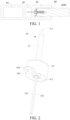
FIG. 1 is a schematic diagram of an aerosol generating device according to an embodiment; -
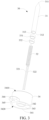
FIG. 2 is a schematic structural diagram of a heater inFIG. 1 from a perspective; -
FIG. 3 is a schematic exploded view of the heater inFIG. 2 from a perspective; -
FIG. 4 is a schematic cross-sectional view of the heater inFIG. 2 from a perspective; -
FIG. 5 is a schematic structural diagram of a base according to another embodiment; -
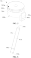
FIG. 6 is a schematic diagram of a housing according to another embodiment; -
FIG. 7 is a schematic structural diagram of a heater according to another embodiment; -
FIG. 8 is a schematic structural diagram of a heater according to another embodiment; -
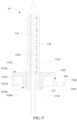
FIG. 9 is a schematic structural diagram of a heater according to another embodiment; -
FIG. 10 is a schematic structural diagram of a heater according to another embodiment; -
FIG. 11 is a schematic structural diagram of a mold for molding a base outside a housing according to an embodiment; -
FIG. 12 is a schematic diagram of clamping models; and -
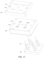
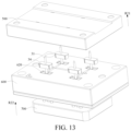
FIG. 13 is a schematic diagram of demolding after a base is molded. - For ease of understanding of this application, this application is described below in more detail with reference to the accompanying drawings and specific implementations.
- An embodiment of this application provides an aerosol generating device. For a structure thereof, refer to
FIG. 1 . The aerosol generating device includes: - a chamber, having an
opening 40, where during use, anaerosol generating article 1000 is removably received in the chamber through theopening 40 of the chamber; - a
heater 30 at least partially extending in the chamber, inserted into theaerosol generating article 1000 for heating when theaerosol generating article 1000 is received in the chamber, so that theaerosol generating article 1000 releases a plurality of volatile compounds, where the volatile compounds are formed by heating only; - a
battery cell 10, configured to supply electricity; and - a
circuit 20, configured to guide a current between thebattery cell 10 and theheater 30. - In a preferred embodiment, a direct current supply voltage provided by the
battery cell 10 ranges from about 2.5 V to about 9.0 V, and an amperage of a direct current that thebattery cell 10 can provide ranges from about 2.5 A to about 20 A. - In a preferred embodiment, the
heater 30 is substantially in a shape of a pin, a needle, a bar, a rod, a column, a sheet, or a plate, which facilitates insertion into theaerosol generating article 1000. In addition, theheater 30 may have a length of about 12 to 20 millimeters, and an outer diameter of about 2 to 4 millimeters. - Further, in an optional implementation, the
aerosol generating article 1000 is preferably made of a tobacco-containing material that releases a volatile compound from a substrate when being heated, or a non-tobacco material suitable for electric heating and smoking after being heated. Theaerosol generating article 1000 preferably uses a solid substrate. The solid substrate may include one or more of powders, particles, fragmented strips, strips, or slices of one or more of vanilla leaves, tobacco leaves, homogeneous tobacco, and expanded tobacco. Alternatively, the solid substrate may include additional tobacco or non-tobacco volatile aroma compounds to be released when the substrate is heated. - During implementation, the
heater 30 may usually include a resistive heating element and auxiliary base materials assisting in fixing and preparing the resistive heating element. For example, in some implementations, the resistive heating element is in a shape or form of a spiral coil. Alternatively, in some other implementations, the resistive heating element is in a form of a conductive track that is combined on the substrate. Alternatively, in some other implementations, the resistive heating element is in a shape of a slice. - Further,
FIG. 2 to FIG. 4 are schematic diagrams of aheater 30 according to an embodiment. Theheater 30 in this embodiment includes a freefront end 311 and atail end 312 that are opposite along a length direction. The freefront end 311 is a conical tip, to be inserted into theaerosol generating article 1000. Specifically, theheater 30 includes:
ahousing 31, configured into an external shape of a pin, a needle, a column, or a bar, where two opposite ends of thehousing 31 along a length direction respectively define a freefront end 311 and atail end 312 of theheater 30; and thehousing 31 has acavity 313 extending between the freefront end 311 and thetail end 312. Thecavity 313 forms an opening or an exposure at thetail end 312, to facilitate assembly of each functional component inside thecavity 313. - In some embodiments, the
housing 31 is heat-conducive; and thehousing 31 is made of a heat-conductive material. Thehousing 31 may be made of ceramic such as aluminum ceramic or zirconium ceramic, or may be made of glass, or may be made of metal or alloy such as iron-aluminum alloy or stainless steel. - In this embodiment, the
cavity 313 of thehousing 31 is provided with: - a
resistive heating coil 32; and - a
conductive pin 321 and aconductive pin 322, respectively connected to two ends of theresistive heating coil 32, to supply electricity to theresistive heating coil 32, where theconductive pin 321 and theconductive pin 322 at least partially extend from inside thecavity 313 to outside thetail end 312, which facilitates connection to thecircuit 20. In addition, theconductive pin 321 is connected to an upper end of theresistive heating coil 32 in a manner such as soldering, and extends through theresistive heating coil 32 to outside thetail end 312. Theconductive pin 322 is directly connected to a lower end of theresistive heating coil 32 in a manner such as soldering. Theconductive pin 321 and theconductive pin 322 have a diameter of about 0.1 to 0.5 mm. Alternatively, in some specific embodiments, theconductive pin 321 and theconductive pin 322 have a diameter of 0.3 mm. - During implementation, the
housing 31 and theresistive heating coil 32 held in thehousing 31 form a heating part configured to be inserted into theaerosol generating article 1000 for heating. - Alternatively, in some other variant embodiments, a rod-shaped heating component defines the heating part configured to be inserted into the
aerosol generating article 1000 for heating. For example, the heating component may further include: a rod-shaped electrically isolating substrate such as ceramic or a polymer, and a resistive heating track formed or combined on the electrically isolating substrate. - In some implementations, the
housing 31 has an outer diameter of about 2.0 to 2.8 mm, and a wall thickness of about 0.1 to 0.3 mm. Therefore, an inner diameter of thecavity 313 of thehousing 31 is about 1.5 to 2.1 mm, and a length of thecavity 313 is about 12 to 15 mm. - In an optional implementation, the
resistive heating coil 32 is made of a metal material with an appropriate impedance, a metal alloy, graphite, carbon, conductive ceramic, or another composite material of a ceramic material and a metal material. A suitable metal or alloy material includes at least one of nickel, cobalt, zirconium, titanium, nickel alloy, cobalt alloy, zirconium alloy, titanium alloy, nickel-chromium alloy, nickel-iron alloy, iron-chromium alloy, iron-chromium-aluminum alloy, iron-manganese-aluminum based alloy, or stainless steel. Certainly, after assembly, theresistive heating coil 32 and an inner wall of thecavity 313 of thehousing 31 are insulated from each other. In addition, during use, thehousing 31 receives or transfers heat of theresistive heating coil 32 to heat theaerosol generating article 1000. In some embodiments, an insulation layer is formed on the surface of theresistive heating coil 32 through spraying, deposition, or surface oxidation, to cause theresistive heating coil 32 to be insulated from the inner wall of thecavity 313 of thehousing 31. - In addition, in some embodiments, the
conductive pin 321 and/or theconductive pin 322 have a diameter of about 0.1 to 0.5 mm; and theconductive pin 321 and/or theconductive pin 322 have a length of about 20 to 40 mm. Moreover, theconductive pin 321 and/or theconductive pin 322 are made of a metal or an alloy with a low electrical resistance, for example, gold, silver, copper, or an alloy including gold, silver, or copper. Alternatively, in some other embodiments, theconductive pin 321 and/or theconductive pin 322 are a copper wire or a copper conductor having a plated layer such as a nickel layer on the surface. Alternatively, in some other embodiments, theconductive pin 321 and/or theconductive pin 322 may further be sprayed or coated with an insulation layer, for example, a ceramic layer, an enamel layer, or an organic layer beneficial to insulation. For example, in some embodiments, a Teflon insulation tube is sleeved on theconductive pin 321 and/or theconductive pin 322, which facilitates providing insulation. - In addition, the
conductive pin 321 and theconductive pin 322 are spaced apart; a spacing between theconductive pin 321 and theconductive pin 322 is 0.8 mm ± 0.1 mm; or a spacing between theconductive pin 321 and theconductive pin 322 is from 0.7 mm to 0.9 mm. - In addition, the
resistive heating coil 32 is not in contact with theaerosol generating article 1000. - In embodiments shown in
FIG. 3 andFIG. 4 , a cross-sectional shape of a wire material of theresistive heating coil 32, which is configured in a form of a solenoid coil, is a shape different from a regular circle. In the implementations shown inFIG. 3 andFIG. 4 , a cross section of the wire material of theresistive heating coil 32 has a size extending in an axial direction that is greater than a size extending in a radial direction perpendicular to the axial direction, so that the cross section of theresistive heating coil 32 is in a flat rectangular shape. - Simply, comparing the
resistive heating coil 32 constructed above with a conventional spiral heating coil formed by a wire with a circular cross section, the wire material is completely or at least flattened in form. Therefore, the wire material extends to a small extent in the radial direction. In this way, energy loss in theresistive heating coil 32 can be reduced. Particularly, this promotes transfer of heat generated by theresistive heating coil 32 to thehousing 31 in the radial direction. - Alternatively, in some other variant embodiments, the cross section of the wire material of the
resistive heating coil 32 is in a shape of a circle. - In addition, further referring to
FIG. 2 , theheater 30 further includes:
abase 34, at least partially surrounding or combined on thehousing 31. Thebase 34 is basically arranged near thetail end 312, and the aerosol generating device clamps or holds thebase 34, so that theheater 30 is stably mounted and fixed in the device. In addition, thebase 34 basically avoids theresistive heating coil 32. Alternatively, thebase 34 is basically located at an end of theresistance heating coil 32 near thetail end 312. Alternatively, in some other embodiments, thebase 34 is closer to thetail end 312 than theresistive heating coil 32 is. Alternatively, in some other embodiments, thebase 34 is arranged in a staggered manner relative to theresistive heating coil 32 along a length of theheater 30. Alternatively, in some other embodiments, a spacing between the base 34 and theresistive heating coil 32 along the length of theheater 30 is greater than 1 mm. - In some embodiments, the
base 34 is independently prepared, and then is combined on thehousing 31 in a manner such as riveting or mechanical fixing. - Alternatively, in some other embodiments, the
base 34 is molded around thehousing 31 by using a moldable material. Thebase 34 is made of an organic polymer such as PEEK, polytetrafluoroethylene, polyurethane, or a polyester resin, or is made of a moldable material such as ceramic. - In addition, in some embodiments, the
circuit 20 controls electricity provided by the battery core 21 to theheater 30, so that during use, a temperature of a part of the heating part and/or thehousing 31 surrounded by thebase 34 is less than 340°C. Alternatively, in some other embodiments, during operation, a temperature of a part of the heating part and/or thehousing 31 surrounded by thebase 34 is less than 320°C. - In addition, further referring to
FIG. 2 to FIG. 4 , thebase 34 has afirst side 3410 and asecond side 3420 facing away from each other along a longitudinal direction. During implementation, thefirst side 3410 faces toward or is near the freefront end 311, and thesecond side 3420 faces toward or is near thetail end 312. Moreover, after assembly, a surface of thefirst side 3410 of thebase 34 is flush with an inner bottom wall of the chamber that faces away from theopening 40. Moreover, after assembly, at least a part of the surface of thefirst side 3410 of thebase 34 is exposed to the chamber. - The surface of the
first side 3410 of thebase 34 is substantially perpendicular to a central axis of thehousing 31 and/or the heating part. Alternatively, in some embodiments, an angle between the central axis of thehousing 31 and/or the heating part and a normal line perpendicular to the surface of thefirst side 3410 of thebase 34 is less than 1°. Alternatively, in some embodiments, the angle between the central axis of thehousing 31 and/or the heating part and the normal line perpendicular to the surface of thefirst side 3410 of thebase 34 is less than 0.5°. - In addition, further referring to
FIG. 2 to FIG. 4 , thebase 34 includes: - an
outer side wall 341 and aninner side wall 342 facing away from each other in the radial direction; where theouter side wall 341 defines an outer surface that surrounds thebase 34 along a peripheral direction, and theinner side wall 342 defines an inner surface that surrounds thehousing 31; and - a
cavity 343, located between theouter side wall 341 and theinner side wall 342; where thecavity 343 is closed on thefirst side 3410, and thecavity 343 is open on thesecond side 3420. - Moreover, the
outer side wall 341 and theinner side wall 342 are connected at thefirst side 3410 and are not connected at thesecond side 3420. Moreover, space in thecavity 343 is filled with air, to at least prevent heat of thehousing 31 from being transferred to theouter side wall 341. Alternatively, thecavity 343 is configured to provide thermal insulation. - In some embodiments, the
base 34 has an outer contour shape of approximately a circle, a square, a polygon, or the like. - In addition, further referring to
FIG. 2 to FIG. 4 , thesecond side 3420 of thebase 34 is basically flush with thetail end 312 of thehousing 31. - Moreover, in some embodiments, an extension size of the
base 34 along a longitudinal direction of theheater 30 is 3 to 6 mm. - Further, referring to
FIG. 2 to FIG. 4 , the base 34 further includes:
one or more connectingparts 344 arranged around thebase 34 and/or theouter side wall 341 along a peripheral direction, where the connectingpart 344 may be provided with a fastening structure such as ascrew hole 345, a connecting hole, or a connecting slot, and during assembly, a screw, a hook, or the like is fitted with the fastening structure such as thescrew hole 345 of the connectingpart 344, to fasten thebase 34 and/or theheater 30 in the aerosol generating device. - In the embodiments shown in
FIG. 2 to FIG. 4 , the connectingpart 344 extends from theouter side wall 341 along the radial direction, the connectingpart 344 is convex relative to theouter side wall 341, and thescrew hole 345 runs through the connectingpart 344 along a longitudinal direction of thebase 34. - In the embodiment shown in
FIG. 4 , theinner side wall 342 is slightly more convex than theouter side wall 341 on thesecond side 3420. For example, inFIG. 4 , theinner side wall 342 exceeds theouter side wall 341 by 0.4 mm on thesecond side 3420. Alternatively, in some implementations, theouter side wall 341 and theinner side wall 342 are flush at thesecond side 3420. Alternatively, in some other embodiments, theouter side wall 341 is slightly more convex than theinner side wall 342 on thesecond side 3420. - Alternatively,
FIG. 5 is a schematic diagram of abase 34c according to another variant embodiment. In this embodiment, thebase 34c includes:
anouter side wall 341c, where aslot 3411c is defined on theouter side wall 341c, and theslot 3411c surrounds theouter side wall 341c and/or thebase 34c in a peripheral direction. During assembly, the aerosol generating device at least partially extends into theslot 3411c, to prevent thebase 34c from moving in an axial direction. In addition, the aerosol generating device at least partially extends into theslot 3411c, so that thebase 34 and/or theheater 30 can also be fastened in the aerosol generating device in a compressing manner. - Alternatively, in the embodiment shown in
FIG. 5 , thebase 34c further includes:
a connectingpart 344c extending from theouter side wall 341c to outside thesecond side 3420c; where there may be one or more connectingparts 344c, and a plurality of connectingparts 344c may alternatively be arranged around theouter side wall 341c in the peripheral direction. - The connecting
part 344c is convex relative to thesecond side 3420c along the longitudinal direction. In addition, during assembly, thescrew hole 345c in the connectingpart 344c is screwed, to fasten thebase 34c and/or theheater 30 in the aerosol generating device. - In addition, further referring to
FIG. 2 to FIG. 4 , theheater 30 further includes:
at least one annular element, for example, anannular element 331 and anannular element 332, surrounding and combined on at least a part of the outer surface of thehousing 31. In addition, theannular element 331 and theannular element 332 are arranged spaced apart along a longitudinal direction of thehousing 31. - In addition, the
inner side wall 342 of thebase 34 has apart 3421 that is snapped between theannular element 331 and theannular element 332. Further, after assembly, thepart 3421 abuts against theannular element 331 and/or theannular element 332 along the longitudinal direction. Alternatively, thepart 3421 is clamped by theannular element 331 and theannular element 332. Therefore, theannular element 331 and theannular element 332 are configured to prevent the base 34 from moving relative to thehousing 31 along the longitudinal direction of thehousing 31. - There is no gap between the
part 3421 of the base 34 that is molded and the outer surface of thehousing 31, or a gap or a spacing is less than 0.05 mm. If thepart 3421 of thebase 34 is separately prepared and then is riveted or mechanically fixed to the outer surface of thehousing 31, there may be an assembly gap of 0.05 mm. In comparison, thepart 3421 is more stably in contact with theannular element 331 and/or theannular element 332 according to the manner in this embodiment. - In some implementations, the
annular element 331 and theannular element 332 are combined on the outer surface of thehousing 31 in a manner such as riveting. - In some implementations, the
annular element 331 and theannular element 332 are made of a metal or alloy material such as stainless steel, brass, aluminum alloy, or titanium alloy. - In some specific implementations, the
annular element 331 and/or theannular element 332 have a color different from that of the outer surface of thehousing 31. For example, thehousing 31 is made of stainless steel, and the outer surface of thehousing 31 is of a silver color; and theannular element 331 and/or theannular element 332 are made of brass, and theannular element 331 and/or theannular element 332 are yellow. During preparation, it is advantageous that an equipment identifies and locates locations of theannular element 331 and/or theannular element 332, and then assembles and prepares thebase 34 around theannular element 331 and/or theannular element 332. - In addition, during implementation, the base 34 completely surrounds the
annular element 331 and/or theannular element 332. In other words, after assembly, theannular element 331 and/or theannular element 332 do not extend out or are not exposed outside thebase 34. Moreover, theannular element 331 is closer to thefirst side 3410 of thebase 34, and theannular element 332 is closer to thesecond side 3420 of thebase 34. - In addition, further referring to
FIG. 4 , after assembly, theannular element 331 and/or theannular element 332 are surrounded or encircled by the inner wall of thebase 34, and theannular element 331 and/or theannular element 332 is wrapped or covered by thebase 34. For example, in the implementation shown inFIG. 4 , the surface of thefirst side 3410 of thebase 34 is closer to the freefront end 311 than theannular element 331 is. - Moreover, in some embodiments, the
annular element 332 is closer to thetail end 312 than theannular element 331 is; theannular element 332 is close to or located at thetail end 312 of thehousing 31; inFIG. 4 , theannular element 332 is basically spaced from thetail end 312 of thehousing 31; and a spacing between theannular element 332 and thetail end 312 of thehousing 31 is greater than or equal to 0.5 mm. - Moreover, in some embodiments, extension sizes of the
annular element 331 and/or theannular element 332 along the axial direction are the same. In some specific embodiments, the extension sizes of theannular element 331 and/or theannular element 332 along the axial direction are 0.5 to 2 mm. In addition, in some embodiments, a spacing between theannular element 331 and theannular element 332 is 0.5 to 1 mm. - In addition, in some embodiments, wall thicknesses of the
annular element 331 and theannular element 332 are 0.1 to 0.5 mm. An outer side surface of theannular element 331 and/or theannular element 332 is convex relative to an outer side surface of thehousing 31, and a convex height is 0.1 to 0.5 mm. - Alternatively, in some other variant embodiments, extension sizes of the
annular element 331 and theannular element 332 along the axial direction are different. For example, an extension size of theannular element 331 along the axial direction is greater than an extension size of theannular element 332 along the axial direction. - Further,
FIG. 6 andFIG. 7 are schematic diagrams of aheater 30 according to another embodiment. In this embodiment, theheater 30 includes: - a
housing 31a, where at least one groove orconcave cavity 314a surrounding thehousing 31a is formed on an outer surface of thehousing 31a, and thehousing 31a is near thetail end 312a; and - a
base 34a, surrounding or combined on thehousing 31a, where aninner side wall 342a of thebase 34a has apart 3421a that extends into or snaps into the groove orconcave cavity 314a. - Further, after assembly, the
part 3421a extends into or snaps into the groove orconcave cavity 314a, thereby facilitating preventing thebase 34a from moving relative to thehousing 31a along a longitudinal direction of thehousing 31a. - Alternatively,
FIG. 8 is a schematic diagram of aheater 30 according to another variant embodiment. In this embodiment, theheater 30 includes: - a
housing 31b, where thehousing 31b has only oneannular element 331b, and theannular element 331b may be formed on an outer surface of thehousing 31b in a manner such as riveting; and - a
base 34b, surrounding and combined on thehousing 31b, where thebase 34b surrounds theannular element 331b, and further, after assembly, theannular element 331b prevents the base 34b from moving relative to thehousing 31b along a longitudinal direction of thehousing 31b. - The
annular element 331b is located between afirst side 3410b and asecond side 3420 of thebase 34b. There is a spacing between theannular element 331b and atail end 312b, and there is a spacing between theannular element 331b and thefirst side 3410b. - Alternatively,
FIG. 9 is a schematic diagram of aheater 30 according to another variant embodiment. In this embodiment, theheater 30 includes: - a
housing 31d, defining a free front end 311d and atail end 312d facing away from each other; - an
annular element 331d and anannular element 332d, spaced apart and successively combined outside thehousing 31d, where an extension length of theannular element 331d along an axial direction is greater than an extension length of theannular element 332d along the axial direction, theannular element 332d is closer to thetail end 312d than theannular element 331d is, and a spacing between theannular element 332d and thetail end 312d is maintained to be greater than or equal to 0.5 mm, or in some other embodiments, theannular element 332d may be flush with thetail end 312d; and - a
base 34d, surrounding and combined on thehousing 31d, where thebase 34d completely surrounds theannular element 331d and completely surrounds theannular element 332d, and aninner side wall 342d of thebase 34d has apart 3421d extending between theannular element 332d and theannular element 331d, to prevent thebase 34d from moving relative to thehousing 31d in a longitudinal direction. - Moreover, in this embodiment, the
annular element 331d is flush with thefirst side 3410d of thebase 34d, and theannular element 332d is flush with thesecond side 3420d of thebase 34d. Theannular element 331d is flush with thefirst side 3410d of thebase 34d, and this is beneficial to precise control and positioning of an injection amount of an injection-molding material in a process of molding thebase 34d. - Moreover, in this embodiment, there is a distance d12 between the
base 34d and thetail end 312d of thehousing 31d, and the distance d12 is greater than 0.5 mm. Further, during implementation, astair 3430d is defined between thebase 34d and thetail end 312d of thehousing 31d. During molding, an equipment or a model completes material injection of thebase 34d at the position, and this facilitates preventing molding slurry from overflowing out of thetail end 312d during the injection process, and improving verticality between thesecond base 34d and thehousing 31d. In addition, during implementation, thestair 3430d facilitates solidification and demolding of thebase 34d. - Alternatively,
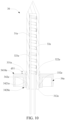
FIG. 10 is a schematic diagram of aheater 30 according to another variant embodiment. In this embodiment, theheater 30 includes: - a
housing 31e, defining a free front end 311e and atail end 312e facing away from each other; - an
annular element 331e and anannular element 332e, spaced apart and successively combined outside thehousing 31e, where an extension length of theannular element 331e along an axial direction is greater than an extension length of theannular element 332e along the axial direction, theannular element 332e is closer to thetail end 312e than theannular element 331e is, and a spacing may be maintained between theannular element 332e and thetail end 312e, or theannular element 332d may be flush with thetail end 312d; and - a
base 34e, surrounding and combined on thehousing 31e, where thebase 34e surrounds a part of theannular element 331e and completely surrounds theannular element 332e, and aninner side wall 342e of thebase 34e has apart 3421e extending between theannular element 332e and theannular element 331e, to prevent thebase 34e from moving relative to thehousing 31e in a longitudinal direction. - In addition, after assembly, at least a part of the
annular element 331e is convex relative to thefirst side 3410e of thebase 34e, or at least a part of theannular element 331e extends out or is exposed outside thefirst side 3410e of thebase 34e. - In addition, in an embodiment, a length or size d11 by which the
annular element 331e extends out or is exposed outside thefirst side 3410e of thebase 34e is 1.0 to 2.0 mm. For example, in a specific embodiment, the length d11 by which theannular element 331e extends out of thefirst side 3410e of thebase 34e is 1.3 mm. This facilitates preventing thebase 34e from scraping a bare surface of thehousing 31e near the free front end 311e during assembly or preparation. - Further,
FIG. 11 to FIG. 13 are schematic diagrams of molding abase 34 outside ahousing 31 by using a model according to an embodiment. As shown in the figure, the model includes anupper model 500, alower model 600, and amovable jig 700. - A surface of the
lower model 600 facing toward theupper model 500 has a holdingcavity 610 for accommodating and holding thehousing 31, and ashaping cavity 620 surrounding the holdingcavity 610 for injection-molding of thebase 34. - A
tubular support member 710 is disposed on themovable jig 700, and thehousing 31 is inserted into thesupport member 710 to be held; and thesupport member 710 of themovable jig 700 passes through from a lower side of thelower model 600 to an upper side of the holdingcavity 610. - In some embodiments, after the
movable jig 700 and thelower model 600 are assembled, thesupport member 710 always passes through to the upper side of the holdingcavity 610, and this is convenient to assemble thehousing 31 on thesupport member 710. After assembly, themovable jig 700 is then moved downward, until thehousing 31 held on thesupport member 710 is moved to a predetermined position in the holdingcavity 610. - Then, the
upper model 500 and thelower model 600 are clamped, and theupper model 500 closes theshaping cavity 620. - In addition, an
avoidance hole 510 is provided on theupper model 500, to enable thehousing 31 held in the holdingcavity 610 to be inserted in when the models are clamped; and aninjection opening 520 is provided on theupper model 500, and the injection opening 520 is in communication with the shapingcavity 620, so that a moldable material for forming thebase 34 is injected to theshaping cavity 620 through the injection opening 520, and the moldable material is solidified outside thehousing 31 to form thebase 34. - Referring to
FIG. 11 , the model clamping process includes the following steps. - The
movable jig 700 is first moved downward as shown by an arrow R11 inFIG. 12 , so that thehousing 31 on thesupport member 710 is moved to a predetermined position in the holdingcavity 610. - Then, as shown by an arrow R12 in
FIG. 12 , theupper model 500 is moved to thelower model 600 to close thecavity 620, and then injection may be performed. - Referring to
FIG. 13 , the demolding process includes the following steps. - The
upper model 500 is first separated from thelower model 600 as shown by an arrow R21 inFIG. 13 , to open the shapingcavity 620. - Then, the
jig 700 is moved as shown by an arrow R22 inFIG. 13 , to eject thehousing 31 in which thebase 34 is molded from the shapingcavity 620 from an upper side; and then, thehousing 31 in which thebase 34 is molded is extracted from thesupport member 710 of thejig 700, to obtain theheater 30. - In addition, during implementation, the
annular element 331 and theannular element 332 outside thehousing 31 can further be configured to position themovable jig 700 in a movement process. - Moreover, in some implementations, a tolerance or an error control of a wall thickness of a tube wall of the
housing 31 is less than 0.015 mm, and this facilitates preventing flashing and sagging during injection and demolding processes in molding thebase 34. - It should be noted that, the specification of this application and the accompanying drawings thereof illustrate preferred embodiments of this application, but are not limited to the embodiments described in this specification. Further, a person of ordinary skill in the art may make improvements or modifications according to the above descriptions, and such improvements and modifications shall all fall within the protection scope of the appended claims of this application.
Claims (32)
- An aerosol generating device, configured to heat an aerosol generating article to generate an aerosol, and comprising:a heater, configured to heat the aerosol generating article, wherein the heater comprises a free front end and a tail end facing away from each other along a length direction; anda heating part, at least partially extending between the free front end and the tail end, to be inserted into the aerosol generating article for heating;at least one annular element, surrounding or combined with the heating part; anda base, at least partially surrounding the heating part, and being arranged to provide structural support for the heating part to keep the heating part in the aerosol generating device, wherein the base comprises a combining part coupled to an outer surface of the heating part, and the combining part abuts against the annular element along the length direction of the heating part, to prevent the base from moving relative to the heating part along the length direction of the heating part.
- The aerosol generating device according to claim 1, wherein the heating part comprises:a housing, at least partially extending between the free front end and the tail end, wherein a first cavity is disposed in the housing; anda resistive heating coil, located in the first cavity.
- The aerosol generating device according to claim 2, wherein the resistive heating coil is constructed to be a solenoid coil; and
an extension size of a cross section of a wire material of the resistive heating coil in an axial direction is greater than an extension size of the cross section in a radial direction. - The aerosol generating device according to any one of claims 1 to 3, wherein the at least one annular element comprises a metal or an alloy.
- The aerosol generating device according to any one of claims 1 to 3, wherein a color of an outer surface of the at least one annular element is different from a color of the outer surface of the heating part.
- The aerosol generating device according to any one of claims 1 to 3, wherein an extension size of the at least one annular element along the length direction of the heating part is 0.5 to 2 mm; and/or
the extension dimension of the at least one annular element along the length direction of the heating part is less than an extension dimension of the base along the length direction of the heating part. - The aerosol generating device according to any one of claims 1 to 3, wherein a wall thickness of the annular element is 0.1 to 0.5 mm.
- The aerosol generating device according to any one of claims 1 to 3, wherein the base is molded around a part of the heating part by using a moldable material, to couple the base to the heating part.
- The aerosol generating device according to claim 8, wherein the base comprises an organic polymer.
- The aerosol generating device according to any one of claims 1 to 3, wherein the at least one annular element is flush with the tail end.
- The aerosol generating device according to any one of claims 1 to 3, wherein a distance between the at least one annular element and the tail end is greater than 0.5 mm.
- The aerosol generating device according to any one of claims 1 to 3, wherein the base comprises a first surface near or facing toward the free front end; and
the at least one annular element is surrounded in the base, and is flush with the first surface. - The aerosol generating device according to any one of claims 1 to 3, wherein the base comprises a first surface near or facing toward the free front end; and
the at least one annular element partially extends from inside the base to outside the first surface. - The aerosol generating device according to any one of claims 1 to 3, wherein the base is further provided with:
one or more connecting parts arranged circumferentially around the base, wherein the base is fixedly connected to the aerosol generating device through the connecting part. - The aerosol generating device according to any one of claims 1 to 3, wherein the at least one annular element at least comprises:
a first annular element and a second annular element, arranged spaced apart along a length direction of the heating part, wherein the combining part is at least partially located between the first annular element and the second annular element. - The aerosol generating device according to any one of claims 1 to 3, wherein the base comprises: an inner side wall near or at least partially combined with the heating part, and an outer side wall facing away from the inner side wall; and
at least one second cavity, located between the inner side wall and the outer side wall, to provide thermal insulation between the inner side wall and the outer side wall. - The aerosol generating device according to claim 16, wherein the base comprises a first side near or facing toward the free front end, and a second side facing away from the first side; and
the at least one second cavity is open on the second side, and the at least one second cavity is closed on the first side. - The aerosol generating device according to any one of claims 1 to 3, wherein no gap exists between the combining part and the heating part; and/or
a gap between the combining part and the heating part is less than 0.05 mm. - The aerosol generating device according to any one of claims 1 to 3, wherein the base comprises a first surface near or facing toward the free front end; and
an angle between a central axis of the heating part and a normal line perpendicular to the first surface is less than 1°. - The aerosol generating device according to claim 2, wherein in an axial direction of the resistive heating coil, the resistive heating coil comprises a first end near the free front end, and a second end near the tail end; andthe heating part further comprises: a first conductive pin and a second conductive pin configured to supply electricity to the resistive heating coil, whereinthe first conductive pin is connected to the first end, and at least partially extends from the first end beyond the tail end;the second conductive pin is connected to the second end, and at least partially extends from the second end beyond the tail end; anda spacing between the first conductive pin and the second conductive pin is in a range from 0.7 mm to 0.9 mm.
- The aerosol generating device according to any one of claims 1 to 3, further comprising:a battery cell, configured to supply electricity; anda circuit, configured to control electricity provided by the battery cell to the heater, to keep a temperature of a part of the heating part surrounded by the base less than 340°C.
- An aerosol generating device, configured to heat an aerosol generating article to generate an aerosol, and comprising:a heater, configured to heat the aerosol generating article, wherein the heater comprises a free front end and a tail end facing away from each other along a length direction; anda heating part, at least partially extending between the free front end and the tail end, to be inserted into the aerosol generating article for heating;at least one annular element, surrounding or combined with the heating part; anda base, molded around a part of the heating part and the at least one annular element by using a moldable material, to couple the base to the heating part and the at least one annular element.
- An aerosol generating device, configured to heat an aerosol generating article to generate an aerosol, and comprising:a heater, configured to heat the aerosol generating article, wherein the heater comprises a free front end and a tail end facing away from each other along a length direction; anda heating part, at least partially extending between the free front end and the tail end, to be inserted into the aerosol generating article for heating;a first annular element, surrounding or combined with the heating part;a second annular element, surrounding or combined with the heating part, wherein the second annular element and the first annular element are arranged spaced apart along a length direction of the heating element; anda base, at least partially molded between the first annular element and the second annular element and around a part of the heating part by using a moldable material.
- An aerosol generating device, configured to heat an aerosol generating article to generate an aerosol, and comprising:a heater, configured to heat the aerosol generating article, wherein the heater comprises a free front end and a tail end facing away from each other along a length direction; anda housing, at least partially extending between the free front end and the tail end, to be inserted into the aerosol generating article;a resistive heating coil, accommodated and held in the housing;at least one groove or concave cavity, defined by an outer surface of the housing; anda base, molded around a part of the housing by using a moldable material, and at least partially extending into the at least one groove or concave cavity, to prevent the base from moving relative to the housing along a length direction of the housing.
- An aerosol generating device, configured to heat an aerosol generating article to generate an aerosol, and comprising:a heater, configured to heat the aerosol generating article, wherein the heater comprises a free front end and a tail end facing away from each other along a length direction; anda heating part, at least partially extending between the free front end and the tail end, to be inserted into the aerosol generating article for heating;a base, at least partially surrounding or combined with the heating part; wherein the aerosol generating device holds the heater by using the base; and the base comprises: an inner side surface surrounding or combined with the heating part, and an outer side surface facing away from the inner side surface; andat least one second cavity, located between the inner side surface and the outer side surface, to reduce transfer of heat of the heating part to the outer side surface.
- A heater for an aerosol generating device, wherein the heater comprises a free front end and a tail end facing away from each other along a length direction, anda heating part, at least partially extending between the free front end and the tail end, to be inserted into an aerosol generating article for heating;at least one annular element, surrounding or combined with the heating part; anda base, at least partially surrounding the heating part, to provide structural support for the heating part, wherein the base comprises a combining part coupled to an outer surface of the heating part, and the combining part abuts against the at least one annular element along the length direction of the heating part, to prevent the base from moving relative to the heating part along the length direction of the heating part.
- A heater for an aerosol generating device, wherein the heater comprises a free front end and a tail end facing away from each other along a length direction, anda heating part, at least partially extending between the free front end and the tail end, to be inserted into an aerosol generating article for heating;a base, at least partially surrounding or combined with the heating part, to provide structural support for the heating part, wherein the base comprises:an inner side surface surrounding or combined with the heating part, and an outer side surface facing away from the inner side surface; andat least one second cavity, located between the inner side surface and the outer side surface, to reduce transfer of heat of the heating part to the outer side surface.
- An aerosol generating device, configured to heat an aerosol generating article to generate an aerosol, and comprising:a heater, configured to heat the aerosol generating article, wherein the heater comprises a free front end and a tail end facing away from each other along a length direction; anda heating part, at least partially extending between the free front end and the tail end, to be inserted into the aerosol generating article for heating;a base, at least partially surrounding the heating part, and being arranged to provide structural support for the heating part to keep the heating part in the aerosol generating device, whereinthe base comprises a first surface near or facing toward the free front end; andan angle between a central axis of the heating part and a normal line perpendicular to the first surface is less than 1°.
- An aerosol generating device, configured to heat an aerosol generating article to generate an aerosol, and comprising:
a heater, configured to heat the aerosol generating article, wherein the heater comprises:a heating part, configured to be inserted into the aerosol generating article for heating, and having a free front end and a tail end facing away from each other along a length direction; anda base, molded around a part of the heating part by using a moldable material, and arranged to provide structural support for the heating part, wherein a spacing exists between the base and the tail end of the heating part, so that a stair is defined between the base and the heating part near the tail end; andthe spacing between the base and the tail end of the heating part is greater than 0.5 mm. - The aerosol generating device according to claim 29, wherein the heating part comprises:a housing, at least partially extending between the free front end and the tail end, wherein a first cavity is disposed in the housing; anda resistive heating coil, located in the first cavity.
- The aerosol generating device according to claim 30, wherein the resistive heating coil is constructed to be a solenoid coil; and
an extension size of a cross section of a wire material of the resistive heating coil in an axial direction is greater than an extension size of the cross section in a radial direction. - The aerosol generating device according to any one of claims 29 to 31, wherein the base further comprises:an inner side surface surrounding or combined with the heating part, and an outer side surface facing away from the inner side surface; andat least one second cavity, located between the inner side surface and the outer side surface, to reduce transfer of heat of the heating part to the outer side surface.
Applications Claiming Priority (2)
| Application Number | Priority Date | Filing Date | Title |
|---|---|---|---|
| CN202211235276.9A CN117898481A (en) | 2022-10-10 | 2022-10-10 | Gas mist generating device and heater for gas mist generating device |
| PCT/CN2023/122205 WO2024078346A1 (en) | 2022-10-10 | 2023-09-27 | Aerosol generating device and heater for aerosol generating device |
Publications (2)
| Publication Number | Publication Date |
|---|---|
| EP4581962A1 true EP4581962A1 (en) | 2025-07-09 |
| EP4581962A4 EP4581962A4 (en) | 2025-12-31 |
Family
ID=90668759
Family Applications (1)
| Application Number | Title | Priority Date | Filing Date |
|---|---|---|---|
| EP23876549.9A Pending EP4581962A4 (en) | 2022-10-10 | 2023-09-27 | Aerosol generator and heater for aerosol generator |
Country Status (3)
| Country | Link |
|---|---|
| EP (1) | EP4581962A4 (en) |
| CN (1) | CN117898481A (en) |
| WO (1) | WO2024078346A1 (en) |
Family Cites Families (8)
| Publication number | Priority date | Publication date | Assignee | Title |
|---|---|---|---|---|
| CA2973143A1 (en) * | 2015-01-28 | 2016-08-04 | Philip Morris Products S.A. | Aerosol-generating article with integral heating element |
| CN115708600A (en) * | 2017-04-11 | 2023-02-24 | 韩国烟草人参公社 | Aerosol generating device |
| KR102035313B1 (en) * | 2017-05-26 | 2019-10-22 | 주식회사 케이티앤지 | Heater assembly and aerosol generating apparatus having the same |
| KR102253046B1 (en) * | 2019-03-05 | 2021-05-17 | 주식회사 케이티앤지 | Aerosol generating device and system, and manufacturing method of the aerosol generating device |
| KR102423895B1 (en) * | 2019-11-25 | 2022-07-21 | 주식회사 케이티앤지 | Heater assembly, aerosol generating device and aerosol generating system |
| CN114642278A (en) * | 2020-12-17 | 2022-06-21 | 深圳市合元科技有限公司 | Heater for gas mist generating device and gas mist generating device |
| CN217184851U (en) * | 2022-02-23 | 2022-08-16 | 深圳市合元科技有限公司 | Gas mist generating device and heater for gas mist generating device |
| CN220109143U (en) * | 2022-10-10 | 2023-12-01 | 深圳市合元科技有限公司 | Gas mist generating device and heater for gas mist generating device |
-
2022
- 2022-10-10 CN CN202211235276.9A patent/CN117898481A/en active Pending
-
2023
- 2023-09-27 WO PCT/CN2023/122205 patent/WO2024078346A1/en not_active Ceased
- 2023-09-27 EP EP23876549.9A patent/EP4581962A4/en active Pending
Also Published As
| Publication number | Publication date |
|---|---|
| EP4581962A4 (en) | 2025-12-31 |
| CN117898481A (en) | 2024-04-19 |
| WO2024078346A1 (en) | 2024-04-18 |
Similar Documents
| Publication | Publication Date | Title |
|---|---|---|
| EP4218441B1 (en) | Aerosol generating device | |
| US12256782B2 (en) | Heating device and manufacturing method therefor, and heat-not-burn smoking device | |
| CN214386095U (en) | Heater for gas mist generating device and gas mist generating device | |
| KR102946608B1 (en) | Aerosol generating device and heating assembly thereof | |
| CN104470387A (en) | Heating Assembly For An Aerosol Generating System | |
| CN215958354U (en) | Heater and smoking set comprising same | |
| CN217184851U (en) | Gas mist generating device and heater for gas mist generating device | |
| EP4183275A1 (en) | Aerosol generating device | |
| KR20210128423A (en) | aerosol delivery device | |
| CN212325392U (en) | Heating device and heating non-combustion smoking set | |
| WO2022135570A1 (en) | Aerosol generating device | |
| CN220109144U (en) | Aerosol generating device | |
| CN114983030A (en) | Aerosol generating device and resistance heater for aerosol generating device | |
| CN220875921U (en) | Gas mist generating device and heater for gas mist generating device | |
| CN117898481A (en) | Gas mist generating device and heater for gas mist generating device | |
| CN115119979A (en) | Aerosol generating device and heating component thereof | |
| WO2021260153A1 (en) | Apparatus for heating aerosolisable material | |
| US20250064125A1 (en) | Aerosol generating device and resistive heater for aerosol generating device | |
| CN217826773U (en) | Gas mist generating device and heater for gas mist generating device | |
| CN219781592U (en) | Aerosol generating device and heater for aerosol generating device | |
| CN218605115U (en) | Aerosol generating device and heating assembly thereof | |
| US20240315336A1 (en) | Heating device for aerosol generation apparatus and aerosol generation apparatus | |
| JP7828466B2 (en) | Aerosol generating device and manufacturing method thereof | |
| CN115886339A (en) | Aerosol generating device, heater for aerosol generating device and manufacturing method | |
| CN114642278A (en) | Heater for gas mist generating device and gas mist generating device |
Legal Events
| Date | Code | Title | Description |
|---|---|---|---|
| STAA | Information on the status of an ep patent application or granted ep patent |
Free format text: STATUS: THE INTERNATIONAL PUBLICATION HAS BEEN MADE |
|
| PUAI | Public reference made under article 153(3) epc to a published international application that has entered the european phase |
Free format text: ORIGINAL CODE: 0009012 |
|
| STAA | Information on the status of an ep patent application or granted ep patent |
Free format text: STATUS: REQUEST FOR EXAMINATION WAS MADE |
|
| 17P | Request for examination filed |
Effective date: 20250401 |
|
| AK | Designated contracting states |
Kind code of ref document: A1 Designated state(s): AL AT BE BG CH CY CZ DE DK EE ES FI FR GB GR HR HU IE IS IT LI LT LU LV MC ME MK MT NL NO PL PT RO RS SE SI SK SM TR |
|
| A4 | Supplementary search report drawn up and despatched |
Effective date: 20251127 |
|
| RIC1 | Information provided on ipc code assigned before grant |
Ipc: A24F 40/46 20200101AFI20251121BHEP Ipc: A24F 40/40 20200101ALI20251121BHEP Ipc: A24F 40/42 20200101ALI20251121BHEP Ipc: A24F 40/70 20200101ALI20251121BHEP |
|
| DAV | Request for validation of the european patent (deleted) | ||
| DAX | Request for extension of the european patent (deleted) |