EP4580083A2 - Method and apparatus for mpdcch performance enhancement - Google Patents
Method and apparatus for mpdcch performance enhancement Download PDFInfo
- Publication number
- EP4580083A2 EP4580083A2 EP25169285.1A EP25169285A EP4580083A2 EP 4580083 A2 EP4580083 A2 EP 4580083A2 EP 25169285 A EP25169285 A EP 25169285A EP 4580083 A2 EP4580083 A2 EP 4580083A2
- Authority
- EP
- European Patent Office
- Prior art keywords
- precoder
- antenna port
- reference signal
- time duration
- frequency band
- Prior art date
- Legal status (The legal status is an assumption and is not a legal conclusion. Google has not performed a legal analysis and makes no representation as to the accuracy of the status listed.)
- Pending
Links
Images


Classifications
-
- H—ELECTRICITY
- H04—ELECTRIC COMMUNICATION TECHNIQUE
- H04B—TRANSMISSION
- H04B7/00—Radio transmission systems, i.e. using radiation field
- H04B7/02—Diversity systems; Multi-antenna system, i.e. transmission or reception using multiple antennas
- H04B7/04—Diversity systems; Multi-antenna system, i.e. transmission or reception using multiple antennas using two or more spaced independent antennas
- H04B7/0413—MIMO systems
- H04B7/0456—Selection of precoding matrices or codebooks, e.g. using matrices antenna weighting
-
- H—ELECTRICITY
- H04—ELECTRIC COMMUNICATION TECHNIQUE
- H04L—TRANSMISSION OF DIGITAL INFORMATION, e.g. TELEGRAPHIC COMMUNICATION
- H04L5/00—Arrangements affording multiple use of the transmission path
- H04L5/003—Arrangements for allocating sub-channels of the transmission path
- H04L5/0048—Allocation of pilot signals, i.e. of signals known to the receiver
-
- H—ELECTRICITY
- H04—ELECTRIC COMMUNICATION TECHNIQUE
- H04W—WIRELESS COMMUNICATION NETWORKS
- H04W4/00—Services specially adapted for wireless communication networks; Facilities therefor
- H04W4/70—Services for machine-to-machine communication [M2M] or machine type communication [MTC]
-
- H—ELECTRICITY
- H04—ELECTRIC COMMUNICATION TECHNIQUE
- H04W—WIRELESS COMMUNICATION NETWORKS
- H04W72/00—Local resource management
- H04W72/20—Control channels or signalling for resource management
- H04W72/23—Control channels or signalling for resource management in the downlink direction of a wireless link, i.e. towards a terminal
-
- H—ELECTRICITY
- H04—ELECTRIC COMMUNICATION TECHNIQUE
- H04B—TRANSMISSION
- H04B7/00—Radio transmission systems, i.e. using radiation field
- H04B7/02—Diversity systems; Multi-antenna system, i.e. transmission or reception using multiple antennas
- H04B7/04—Diversity systems; Multi-antenna system, i.e. transmission or reception using multiple antennas using two or more spaced independent antennas
- H04B7/06—Diversity systems; Multi-antenna system, i.e. transmission or reception using multiple antennas using two or more spaced independent antennas at the transmitting station
- H04B7/0613—Diversity systems; Multi-antenna system, i.e. transmission or reception using multiple antennas using two or more spaced independent antennas at the transmitting station using simultaneous transmission
- H04B7/0615—Diversity systems; Multi-antenna system, i.e. transmission or reception using multiple antennas using two or more spaced independent antennas at the transmitting station using simultaneous transmission of weighted versions of same signal
- H04B7/0617—Diversity systems; Multi-antenna system, i.e. transmission or reception using multiple antennas using two or more spaced independent antennas at the transmitting station using simultaneous transmission of weighted versions of same signal for beam forming
-
- H—ELECTRICITY
- H04—ELECTRIC COMMUNICATION TECHNIQUE
- H04B—TRANSMISSION
- H04B7/00—Radio transmission systems, i.e. using radiation field
- H04B7/02—Diversity systems; Multi-antenna system, i.e. transmission or reception using multiple antennas
- H04B7/04—Diversity systems; Multi-antenna system, i.e. transmission or reception using multiple antennas using two or more spaced independent antennas
- H04B7/06—Diversity systems; Multi-antenna system, i.e. transmission or reception using multiple antennas using two or more spaced independent antennas at the transmitting station
- H04B7/0686—Hybrid systems, i.e. switching and simultaneous transmission
-
- H—ELECTRICITY
- H04—ELECTRIC COMMUNICATION TECHNIQUE
- H04L—TRANSMISSION OF DIGITAL INFORMATION, e.g. TELEGRAPHIC COMMUNICATION
- H04L5/00—Arrangements affording multiple use of the transmission path
- H04L5/0001—Arrangements for dividing the transmission path
- H04L5/0014—Three-dimensional division
- H04L5/0023—Time-frequency-space
-
- H—ELECTRICITY
- H04—ELECTRIC COMMUNICATION TECHNIQUE
- H04L—TRANSMISSION OF DIGITAL INFORMATION, e.g. TELEGRAPHIC COMMUNICATION
- H04L5/00—Arrangements affording multiple use of the transmission path
- H04L5/003—Arrangements for allocating sub-channels of the transmission path
- H04L5/0048—Allocation of pilot signals, i.e. of signals known to the receiver
- H04L5/005—Allocation of pilot signals, i.e. of signals known to the receiver of common pilots, i.e. pilots destined for multiple users or terminals
-
- H—ELECTRICITY
- H04—ELECTRIC COMMUNICATION TECHNIQUE
- H04L—TRANSMISSION OF DIGITAL INFORMATION, e.g. TELEGRAPHIC COMMUNICATION
- H04L5/00—Arrangements affording multiple use of the transmission path
- H04L5/003—Arrangements for allocating sub-channels of the transmission path
- H04L5/0048—Allocation of pilot signals, i.e. of signals known to the receiver
- H04L5/0051—Allocation of pilot signals, i.e. of signals known to the receiver of dedicated pilots, i.e. pilots destined for a single user or terminal
-
- H—ELECTRICITY
- H04—ELECTRIC COMMUNICATION TECHNIQUE
- H04L—TRANSMISSION OF DIGITAL INFORMATION, e.g. TELEGRAPHIC COMMUNICATION
- H04L5/00—Arrangements affording multiple use of the transmission path
- H04L5/0091—Signalling for the administration of the divided path, e.g. signalling of configuration information
- H04L5/0094—Indication of how sub-channels of the path are allocated
-
- H—ELECTRICITY
- H04—ELECTRIC COMMUNICATION TECHNIQUE
- H04W—WIRELESS COMMUNICATION NETWORKS
- H04W72/00—Local resource management
- H04W72/04—Wireless resource allocation
- H04W72/044—Wireless resource allocation based on the type of the allocated resource
Definitions
- the present application generally relates to a communication method and apparatus, especially a communication method and apparatus for Machine-Type Communication (MTC) physical downlink control channel (MPDCCH) performance enhancement.
- MTC Machine-Type Communication
- MPDCCH physical downlink control channel
- the Demodulation Reference Signal (DMRS) is used for decoding MTC Physical Downlink Control Channel (MPDCCH), while the Cell-Specific Reference Signal (CRS) is not.
- DMRS Demodulation Reference Signal
- MPDCCH Physical Downlink Control Channel
- CRS Cell-Specific Reference Signal
- the demodulation of MPDCCH is based on DMRS as Enhanced Physical Downlink Control Channel (EPDCCH).
- EPDCCH Enhanced Physical Downlink Control Channel
- One embodiment of the present disclosure provides an apparatus comprising: a receiver that receives a first reference signal, a second reference signal and a control signal; and a processer that decodes the control signal based on at least one of: the first reference signal and the second reference signal, wherein the second reference signal on an antenna port is associated with a precoder, and the antenna port of the second reference signal and the precoder for the antenna port of the second reference signal are adopted within a time duration and a frequency band.
- Another embodiment of the present disclosure provides an apparatus comprising: a transmitter that transmits a first reference signal, a second reference signal and a control signal; and a processer that pre-processes the second reference signal on an antenna port using a precoder, wherein the antenna port of the second reference signal and the precoder for the antenna port of the second reference signal are adopted within a time duration and a frequency band.
- Yet another embodiment of the present disclosure provides a method comprising: receiving a first reference signal, a second reference signal and a control signal; and decoding the control signal based on at least one of: the first reference signal and the second reference signal, wherein the second reference signal on an antenna port is associated with a precoder, and the antenna port of the second reference signal and the precoder for the antenna port of the second reference signal are adopted within a time duration and a frequency band.
- Yet another embodiment of the present disclosure provides a method comprising: transmitting a first reference signal, a second reference signal and a control signal; and pre-processing the second reference signal on an antenna port using a precoder, wherein the antenna port of the second reference signal and the precoder for the antenna port of the second reference signal are adopted within a time duration and a frequency band.
- Embodiments provide the method and apparatus for MPDCCH performance enhancement.
- embodiments are provided under specific network architecture and new service scenarios, such as 3GPP 5G, 3GPP LTE Release 8 and onwards.
- network architecture and new service scenarios such as 3GPP 5G, 3GPP LTE Release 8 and onwards.
- Persons skilled in the art know well that, with developments of network architecture and new service scenarios, the embodiments in the subject disclosure are also applicable to similar technical problems.
- Fig. 1 depicts a wireless communication system 100 according to an embodiment of the present disclosure.
- the wireless communication system 100 includes user equipment 101 and base units 102. Even though a specific number of user equipment 101 and base units 102 are depicted in Fig. 1 , one of skill in the art will recognize that any number of user equipment 101 and base units 102 may be included in the wireless communication system 100.
- the user equipment 101 may include computing devices, such as desktop computers, laptop computers, personal digital assistants (PDAs), tablet computers, smart televisions (e.g., televisions connected to the Internet), set-top boxes, game consoles, security systems (including security cameras), vehicle on-board computers, network devices (e.g., routers, switches, modems), or the like.
- the user equipment 101 may include a portable wireless communication device, a smart phone, a cellular telephone, a flip phone, a device having a subscriber identity module, a personal computer, a selective call receiver, or any other device that is capable of sending and receiving communication signals on a wireless network.
- the user equipment 101 includes wearable devices, such as smart watches, fitness bands, optical head-mounted displays, or the like. Moreover, the user equipment 101 may be referred to as subscriber units, mobiles, mobile stations, users, terminals, mobile terminals, wireless terminals, fixed terminals, subscriber stations, user equipment 101, user terminals, a device, or by other terminology used in the art.
- the user equipment 101 may communicate directly with a base unit 102 via uplink (UL) communication signals.
- UL uplink
- the base units 102 may be distributed over a geographic region.
- a base unit 102 may also be referred to as an access point, an access terminal, a base, a base station, a macro cell, a Node-B, an enhanced Node B (eNB), a base units 102, a Home Node-B, a relay node, a device, or by any other terminology used in the art.
- the base units 102 are generally part of a radio access network that may include one or more controllers communicably coupled to one or more corresponding base units 102.
- the wireless communication system 100 is compliant with any type of network that is capable of sending and receiving wireless communication signals.
- the wireless communication system 100 is compliant with a wireless communication network, a cellular telephone network, a Time Division Multiple Access (TDMA)-based network, a Code Division Multiple Access (CDMA)-based network, an Orthogonal Frequency Division Multiple Access (OFDMA)-based network, a Long Term Evolution (LTE) network, a 3rd Generation Partnership Project (3GPP)-based network, 3GPP 5G network, a satellite communications network, a high altitude platform network, and/or other communications networks.
- TDMA Time Division Multiple Access
- CDMA Code Division Multiple Access
- OFDMA Orthogonal Frequency Division Multiple Access
- LTE Long Term Evolution
- 3GPP 3rd Generation Partnership Project
- 3GPP 5G 3rd Generation Partnership Project 5G network
- satellite communications network a high altitude platform network, and/or other communications networks.
- the wireless communication system 100 is compliant with the long-term evolution (LTE) of the 3GPP protocol, wherein the base unit 102 transmits using an orthogonal frequency division multiplexing (OFDM) modulation scheme on the DL and the user equipment 101 transmit on the UL using a single-carrier frequency division multiple access (SC-FDMA) scheme or OFDM scheme. More generally, however, the wireless communication system 100 may implement some other open or proprietary communication protocol, for example, WiMAX, among other protocols.
- LTE long-term evolution
- OFDM orthogonal frequency division multiplexing
- SC-FDMA single-carrier frequency division multiple access
- the base unit 102 may communicate using other communication protocols, such as the IEEE 802.11 family of wireless communication protocols. Further, in some embodiments the base unit 102 may communicate over licensed spectrum, while in other embodiments the base unit 102 may communicate over unlicensed spectrum. The present disclosure is not intended to be limited to the implementation of any particular wireless communication system architecture or protocol. In another embodiment, the base unit 102 may communicate with user equipment 101 using the 3GPP 5G protocols.
- the subject application presents an approach for MPDCCH performance enhancement.
- the base station pre-processes the DMRS of an antenna port and MPDCCH based on a precoder, and transmits the CRS, pre-processed DMRSand MPDCCH to UE. After receiving these signals, UE decodes the MPDCCH based on the CRS and pre-processed DMRS.
- the antenna port of DMRS and the precoder is adopted within a time duration and a frequency band.
- the precoder indicates a relationship between the CRS antenna port and DMRS antenna port since the CRS is not pre-processed with the precoder.
- the precoder set in Table 6.3.4.2.3-1 of Evolved Universal Terrestrial Radio Access (E-UTRA); Physical channels and modulation (3GPP TS36.211) is utilized, where the element of each precoder is a 2 ⁇ 1 complex vector; and if the available port number of CRS is 4, the preocoder set in Table 6.3.4.2.3-2 of 3GPP TS36.211 is utilized, where the element of each precoder is a 4 ⁇ 1 complex vector.
- the precoder set W is selected from Table 6.3.4.2.3-2 of 3GPP TS36.211.
- the initial precoder index of the precoder for the antenna port of DMRS may be determined according to the cell ID or the UE ID. For example, in time duration from 0 to 5 and frequency band from PRB0 to PRB2, for antenna port P107, the initial precoder index is cell ID % N, and for antenna port P109, the initial precoder index is: (cell ID + M1) % N, where M1 may be fixed to 4 or higher layer signalling configured, and N is the total number precoder in the precoder set.
- the method of this disclosure can be implemented on a programmed processor.
- the controllers, flowcharts, and modules may also be implemented on a general purpose or special purpose computer, a programmed microprocessor or microcontroller and peripheral integrated circuit elements, an integrated circuit, a hardware electronic or logic circuit such as a discrete element circuit, a programmable logic device, or the like.
- any device on which there resides a finite state machine capable of implementing the flowcharts shown in the figures may be used to implement the processor functions of this disclosure.
Landscapes
- Engineering & Computer Science (AREA)
- Signal Processing (AREA)
- Computer Networks & Wireless Communication (AREA)
- Mobile Radio Communication Systems (AREA)
- Circuits Of Receivers In General (AREA)
Abstract
Description
- The present application generally relates to a communication method and apparatus, especially a communication method and apparatus for Machine-Type Communication (MTC) physical downlink control channel (MPDCCH) performance enhancement.
- In Rel.13, the Demodulation Reference Signal (DMRS) is used for decoding MTC Physical Downlink Control Channel (MPDCCH), while the Cell-Specific Reference Signal (CRS) is not.
- For Rel.13, the demodulation of MPDCCH is based on DMRS as Enhanced Physical Downlink Control Channel (EPDCCH). In order to enhance the performance of MPDCCH, combining DMRS with CRS is proposed to be considered in Rel. 16
- In order to improve the performance of MPDCCH, an approach for combining DMRS with CRS for MPDCCH demodulation is desired.
- One embodiment of the present disclosure provides an apparatus comprising: a receiver that receives a first reference signal, a second reference signal and a control signal; and a processer that decodes the control signal based on at least one of: the first reference signal and the second reference signal, wherein the second reference signal on an antenna port is associated with a precoder, and the antenna port of the second reference signal and the precoder for the antenna port of the second reference signal are adopted within a time duration and a frequency band.
- Another embodiment of the present disclosure provides an apparatus comprising: a transmitter that transmits a first reference signal, a second reference signal and a control signal; and a processer that pre-processes the second reference signal on an antenna port using a precoder, wherein the antenna port of the second reference signal and the precoder for the antenna port of the second reference signal are adopted within a time duration and a frequency band.
- Yet another embodiment of the present disclosure provides a method comprising: receiving a first reference signal, a second reference signal and a control signal; and decoding the control signal based on at least one of: the first reference signal and the second reference signal, wherein the second reference signal on an antenna port is associated with a precoder, and the antenna port of the second reference signal and the precoder for the antenna port of the second reference signal are adopted within a time duration and a frequency band.
- Yet another embodiment of the present disclosure provides a method comprising: transmitting a first reference signal, a second reference signal and a control signal; and pre-processing the second reference signal on an antenna port using a precoder, wherein the antenna port of the second reference signal and the precoder for the antenna port of the second reference signal are adopted within a time duration and a frequency band.
-
-
Fig. 1 illustrates an example block diagram of a wireless communication system according to an embodiment of the present disclosure. -
Fig. 2 illustrates an example of joint DMRS-CRS channel estimation. -
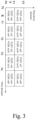
Fig. 3 illustrates another example of joint DMRS-CRS channel estimation. -
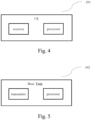
Fig. 4 illustrates an example block diagram of user equipment according to an embodiment of the present disclosure. -
Fig. 5 illustrates an example block diagram of a base unit according to an embodiment of the present disclosure. - The detailed description of the appended drawings is intended as a description of the currently preferred embodiments of the present invention, and is not intended to represent the only form in which the present invention may be practiced. It should be understood that the same or equivalent functions may be accomplished by different embodiments that are intended to be encompassed within the spirit and scope of the present invention.
- Embodiments provide the method and apparatus for MPDCCH performance enhancement. To facilitate understanding, embodiments are provided under specific network architecture and new service scenarios, such as 3GPP 5G, 3GPP LTE Release 8 and onwards. Persons skilled in the art know well that, with developments of network architecture and new service scenarios, the embodiments in the subject disclosure are also applicable to similar technical problems.
-
Fig. 1 depicts awireless communication system 100 according to an embodiment of the present disclosure. - As shown in
Fig. 1 , thewireless communication system 100 includesuser equipment 101 andbase units 102. Even though a specific number ofuser equipment 101 andbase units 102 are depicted inFig. 1 , one of skill in the art will recognize that any number ofuser equipment 101 andbase units 102 may be included in thewireless communication system 100. - The
user equipment 101 may include computing devices, such as desktop computers, laptop computers, personal digital assistants (PDAs), tablet computers, smart televisions (e.g., televisions connected to the Internet), set-top boxes, game consoles, security systems (including security cameras), vehicle on-board computers, network devices (e.g., routers, switches, modems), or the like. According to an embodiment of the present disclosure, theuser equipment 101 may include a portable wireless communication device, a smart phone, a cellular telephone, a flip phone, a device having a subscriber identity module, a personal computer, a selective call receiver, or any other device that is capable of sending and receiving communication signals on a wireless network. In some embodiments, theuser equipment 101 includes wearable devices, such as smart watches, fitness bands, optical head-mounted displays, or the like. Moreover, theuser equipment 101 may be referred to as subscriber units, mobiles, mobile stations, users, terminals, mobile terminals, wireless terminals, fixed terminals, subscriber stations,user equipment 101, user terminals, a device, or by other terminology used in the art. Theuser equipment 101 may communicate directly with abase unit 102 via uplink (UL) communication signals. - The
base units 102 may be distributed over a geographic region. In certain embodiments, abase unit 102 may also be referred to as an access point, an access terminal, a base, a base station, a macro cell, a Node-B, an enhanced Node B (eNB), abase units 102, a Home Node-B, a relay node, a device, or by any other terminology used in the art. Thebase units 102 are generally part of a radio access network that may include one or more controllers communicably coupled to one or morecorresponding base units 102. - The
wireless communication system 100 is compliant with any type of network that is capable of sending and receiving wireless communication signals. For example, thewireless communication system 100 is compliant with a wireless communication network, a cellular telephone network, a Time Division Multiple Access (TDMA)-based network, a Code Division Multiple Access (CDMA)-based network, an Orthogonal Frequency Division Multiple Access (OFDMA)-based network, a Long Term Evolution (LTE) network, a 3rd Generation Partnership Project (3GPP)-based network, 3GPP 5G network, a satellite communications network, a high altitude platform network, and/or other communications networks. - In one implementation, the
wireless communication system 100 is compliant with the long-term evolution (LTE) of the 3GPP protocol, wherein thebase unit 102 transmits using an orthogonal frequency division multiplexing (OFDM) modulation scheme on the DL and theuser equipment 101 transmit on the UL using a single-carrier frequency division multiple access (SC-FDMA) scheme or OFDM scheme. More generally, however, thewireless communication system 100 may implement some other open or proprietary communication protocol, for example, WiMAX, among other protocols. - In other embodiments, the
base unit 102 may communicate using other communication protocols, such as the IEEE 802.11 family of wireless communication protocols. Further, in some embodiments thebase unit 102 may communicate over licensed spectrum, while in other embodiments thebase unit 102 may communicate over unlicensed spectrum. The present disclosure is not intended to be limited to the implementation of any particular wireless communication system architecture or protocol. In another embodiment, thebase unit 102 may communicate withuser equipment 101 using the 3GPP 5G protocols. - The subject application presents an approach for MPDCCH performance enhancement. The base station pre-processes the DMRS of an antenna port and MPDCCH based on a precoder, and transmits the CRS, pre-processed DMRSand MPDCCH to UE. After receiving these signals, UE decodes the MPDCCH based on the CRS and pre-processed DMRS. The antenna port of DMRS and the precoder is adopted within a time duration and a frequency band.
- The precoder indicates a relationship between the CRS antenna port and DMRS antenna port since the CRS is not pre-processed with the precoder. By combining CRS and DMRS with precoders at the UE side, an improved channel estimation can be achieved. Thus, for enhancing the joint DMRS-CRS channel estimation, at least the following items should be determined at the UE side: a frequency band, a time duration and an antenna port for transmitting the MPDCCH, and a precoder associated with the time duration, the frequency band and the antenna port. These items may be indicated by higher layer signalling, implicitly derived from higher layer signaling configured parameters or fixed in specification.
-
Fig. 2 depicts a precoder arrangement in time-frequency domain for joint DMRS-CRS channel estimation. In this embodiment, higher layer signalling indicates an antenna port of DMRS and a precoder for the antenna port of DMRS within a time duration and a frequency band. - As shown in
Fig. 2 , the horizontal axis represents the time domain, and the vertical axis represents the frequency domain. The length of time duration, which is denoted by "X," is 5ms, the size of frequency band, which is denoted by "Y," is 3 Physical Resource Block(PRB), the precoder set is denoted as W = {w0, w1, ...w15}, and the antenna port set is denoted as P = {P107, P108, P 109, and P110}. The preocoder set W adopted for DMRS and MPDCCH may be determined by the total available antenna port number of CRS. For example, if the available antenna port number of CRS is 2, the precoder set in Table 6.3.4.2.3-1 of Evolved Universal Terrestrial Radio Access (E-UTRA); Physical channels and modulation (3GPP TS36.211) is utilized, where the element of each precoder is a 2×1 complex vector; and if the available port number of CRS is 4, the preocoder set in Table 6.3.4.2.3-2 of 3GPP TS36.211 is utilized, where the element of each precoder is a 4×1 complex vector. InFig. 2 , the precoder set W is selected from Table 6.3.4.2.3-2 of 3GPP TS36.211. - As shown in
Fig. 2 , the higher layer signalling indicates that in time duration from 0 to 5 and frequency band from PRB0 to PRB2, the antenna port P107 associated with precoder w0 are adopted by DMRS and the MPDCCH, the other antenna port P109 associated with precoder w7 are adopted by DMRS and the MPDCCH; and the in time duration from 10 to 15 and frequency band from PRB3 to PRB5, and the antenna port P108 associated with the precoder w10 are adopted by DMRS and theMPDCCH or antenna port 110 is associated with precoder w14 are adopted by DMRS and MPDCCH. For example, w0 w7, w10 and w14 are selected from the second column in Table 6.3.4.2.3-2 of 3GPP TS36.211, where the second column suggests the number of layers is 2. - In other embodiments, the preocoder set W may also be determined by higher layer signaling or fixed in specification.
-
Fig. 3 depicts another example of precoder arrangement in time-frequency domain for joint DMRS-CRS channel estimation. - The length of time duration X may be derived from the existing higher layer parameters, or fixed in the specification rather than indicated by the higher layer signaling as shown in
Fig. 2 . As shown inFig. 3 , the length of time duration X may be from T0 to T1 or from T1 to T2. For example, T0 may be 0, T1 may be 5 ms, and T2 may be 10ms. - In one preferred embodiment, the length of time duration X can be determined by the MPDCCH search space of Rmax, which is a maximal repetition number of the MPDCCH. For example, the value of X may be floor (Rmax/N), where floor () is the lower rounding function, and N is the total number of precoders in the precoder set. Assuming that higher layer signalling configures Rmax is 128 and N is 16 (CRS antenna port is 0, 1, 2, or 3), the length of time duration is X=128/16 = 8.
- In another preferred embodiment, the length of time duration X may be determined by Coverage Enhancement (CE) mode of MPDCCH and duplex mode of Frequency Division Duplex (FDD) and Time Division Duplex (TDD). For example, as shown in Table 1, if the CE mode is A and the duplex mode is FDD, the length of time duration X may be 1, 2, 4, or 8 and higher layer signalling indicates the X from {1, 2, 4, 8}; if the CE mode is B and the duplex mode is TDD, the length of time duration X may be 5, 10, 20, or 40 and higher layer signalling indicates the X from {5, 10, 20, 40}.
Table 1. the value of the length of time duration X CE Mode FDD TDD A 1, 2, 4, or 8 1, 5, 10, or 20 B 2, 4, 8, or 16 5, 10, 20, or 40 - In yet another preferred embodiment, □the length of time duration X may also be determined by a scaling factor configured by higher layer signaling and/or interval-DLHoppingConfigCommonModeA/B-r13. If the scaling factor is 1 and the configured interval-DLHoppingConfigCommonModeA/B-r13 is 5ms by higher layer signalling, the length of time duration is interval-DLHoppingConfigCommonModeA/B-r13 multiplied by the scaling factor, which is 5ms×1 = 5ms. For example, for FDD, the scaling factor indicated by higher layer sinalling from a scaling factor set, for example the scaling factor set can be {1, 2, 4, 8}.
- In another preferred embodiment, the length of time duration X may also be determined by the antenna port number of the DMRS or a cyclic prefix type.
- The size of frequency band Y (i.e., the PRB bundling size) can be indicated by the higher layer signaling, derived from the existing higher layer parameters, or fixed in the specification. The size of frequency band Y may be from F0 to F1, or from F1 to F2. For example, F0 may be 0, F1 may be 180 × 3KHz (corresponding to frequency domain size of 3PRB) and F2 may be 180×6KHz (corresponding to frequency domain size of 6PRB).
- For example, in table 2, the the value of the PRB bundling size can be "P1," "P2," "Q1," "Q2," "R1," or "R2," which are determined by higher layer signaling.
Table 2. the value of the PRB bundling size Y numberPRB-Pairs Localized MPDCCH CE mode A CE mode B 2 P1 P2 4 Q1 Q2 6 R1 R2 - In another preferred embodiment, the PRB bundling size is determined by the number of available PRB pairs (i.e., numberPRB-Pairs), CE Mode, and transmission type of MPDCCH (i.e., localized or distributed). For example, if the number of available PRB pairs configured by higher layer signalling is 2, the transmission type of MPDCCH is configured as localized transmission mode, and the CE mode is A, it is determined that the value of the PRB bundling size is 1 according to Table 3.
Table 3. the value of the PRB bundling size Y numberPRB-Pairs Localized MPDCCH Distributed MPDCCH CE mode A CE mode B CE mode A CE mode B 2 1 2 1 2 4 2 4 2 4 6 3 6 3 6 - The starting subframe for adoption of the antenna port of DMRS and the precoder for the antenna port of DMRS may be determined according to a starting subframe of a search space of MPDCCH, an absolute radio frame, or an absolute subframe.
- The starting subframe may also be determined by the search space of MPDCCH. For common search space, the starting subframe is cell-specific, and The starting subframe for adoption of the antenna port of DMRS and the precoder for the antenna port of DMRS is the same as the starting subframe of the common search space.
- For example, if the starting subframe is cell-specific, the starting subframe is related to the absolute subframe (e.g., determined by System Frame Number (SFN) and subframe number).
- The starting precoder index for adoption of the antenna port of DMRS may relates to the cell ID, and the circular order is determined by circular selection from the precoder set. For example, for time domain, the precoder index is determined by the following equation:

- For UE-specific search space, the starting subframe of precoder adoption is UE-specific. For example, the starting subframe of precoder adoption may begin with the the starting subframe of UE-specific search space, and the starting precoder index relates to the UE ID.
- The the antenna port of DMRS may be circularly selected from an antenna port set P{P107, P108, P109, P110}. For example, it can be selected from the antenna port set P according to at least one of: the time duration X, the frequency band Y, and the antenna port of DMRS.
- The precoder for the antenna port of DMRS may be circularly selected from a precoder set W {w0, w1, ..., w15}. For example, it can be selected from the precoder set W according to at least one of: the time duration X, the frequency band Y, and the antenna port of DMRS.
- The initial precoder index of the precoder for the antenna port of DMRS may be determined according to the cell ID or the UE ID. For example, in time duration from 0 to 5 and frequency band from PRB0 to PRB2, for antenna port P107, the initial precoder index is cell ID % N, and for antenna port P109, the initial precoder index is: (cell ID + M1) % N, where M1 may be fixed to 4 or higher layer signalling configured, and N is the total number precoder in the precoder set.
- The antenna port of DMRS may be circularly selected from an antenna port set according to the time duration or the frequency band, and an initial antenna port of DMRS may be determined according to a cell ID or UE ID. The circular order may be configured by higher layer signaling or fixed in the specification.
- Take the embodiment in
Fig. 3 as an example. For the same frequency band (e.g., F0 to F1) and the same antenna port (e.g., P107), the index of precoder in different time duration is:
- In another preferred embodiment, the base unit may transmit a configuration to the UE, and the configuration may include a precoder set W, a size of the frequency band Y, a length of the time duration X, a starting frequency band, an offset of the frequency band, a starting time duration, an offset of the time duration, an initial antenna port, an initial precoder index, an antenna port adoption order pattern, or a step index of the precoder.
-
FIG. 4 depicts a block diagram of user equipment according to the embodiments of the present disclosure. Theuser equipment 101 may include a receiver and a processor. In certain embodiments, theuser equipment 101 may further include an input device, a display, a memory, and/or other elements. In one embodiment, the receiver receives CRS, DMRS and MPDCCH, and the processor decodes MPDCCH based on at least one of: CRS, DMRS, wherein DMRS transmitted on an antenna port is associated with a precoder, and the antenna port of DMRS and the precoder for the antenna port of DMRS are adopted within a time duration and a frequency band. The functions and implementations of all elements in theuser equipment 101 and definitions of related technical terms can refer to the specific descriptions ofFigs. 2 and3 and the foregoing corresponding paragraphs in this specification. -
FIG. 5 depicts a block diagram of a base unit according to the embodiments of the present disclosure. Thebase unit 102 may include a transmitter and a processor. In certain embodiments, thebase unit 102 may further include an input device, a display, a memory, and/or other elements. In one embodiment, a transmitter transmits CRS, DMRS and MPDCCH, and the processor pre-processes the DMRS using a precoder, and the antenna port of DMRS and the precoder for the antenna port of DMRS are adopted within a time duration and a frequency band. The functions and implementations of all elements in the apparatus and definitions of related technical terms can refer to the specific descriptions ofFigs. 2 and3 and the foregoing corresponding paragraphs in this specification. - The method of this disclosure can be implemented on a programmed processor. However, the controllers, flowcharts, and modules may also be implemented on a general purpose or special purpose computer, a programmed microprocessor or microcontroller and peripheral integrated circuit elements, an integrated circuit, a hardware electronic or logic circuit such as a discrete element circuit, a programmable logic device, or the like. In general, any device on which there resides a finite state machine capable of implementing the flowcharts shown in the figures may be used to implement the processor functions of this disclosure.
- While this disclosure has been described with specific embodiments thereof, it is evident that many alternatives, modifications, and variations will be apparent to those skilled in the art. For example, various components of the embodiments may be interchanged, added, or substituted in the other embodiments. Also, all of the elements of each figure are not necessary for operation of the disclosed embodiments. For example, one of ordinary skill in the art of the disclosed embodiments would be capable of making and using the teachings of the present disclosure by simply employing the elements of the independent claims. Accordingly, the embodiments of the present disclosure as set forth herein are intended to be illustrative, not limiting. Various changes may be made without departing from the spirit and scope of the present disclosure.
- In this document, relational terms such as "first," "second," and the like may be used solely to distinguish one entity or action from another entity or action without necessarily requiring or implying any actual such relationship or order between such entities or actions. The terms "comprises," "comprising," or any other variation thereof, are intended to cover a non-exclusive inclusion, such that a process, method, article, or apparatus that comprises a list of elements does not include only those elements but may include other elements not expressly listed or inherent to such process, method, article, or apparatus. An element proceeded by "a," "an," or the like does not, without more constraints, preclude the existence of additional identical elements in the process, method, article, or apparatus that comprises the element. Also, the term "another" is defined as at least a second or more. The terms "including," "having," and the like, as used herein, are defined as "comprising."
- Further aspects of the invention are provided by the subject matter of the following numbered clauses:
- Clause 1. An apparatus comprising: a receiver that receives a first reference signal, a second reference signal and a control signal; and a processer that decodes the control signal based on at least one of: the first reference signal and the second reference signal, wherein the second reference signal on an antenna port is associated with a precoder, and the antenna port of the second reference signal and the precoder for the antenna port of the second reference signal are adopted within a time duration and a frequency band.
- Clause 2. The apparatus of clause 1, wherein the first reference signal is a Cell-Specific Reference Signal (CRS), the second reference signal is a Demodulation Reference Signal (DMRS) and the control signal is MPDCCH.
- Clause 3. The apparatus of clause 1, wherein the antenna port of the second reference signal and the precoder for the antenna port of the second reference signal within the time duration and the frequency band are indicated by a higher layer signaling.
- Clause 4. The apparatus of clause 1, wherein the precoder for the antenna port of the second reference signal is from a precoder set, and the precoder set is selected according to a total available antenna port number of the first reference signal.
-
Clause 5. The apparatus of clause 1, wherein a length of the time duration is determined by at least one of: a maximal repetition number of the control signal, a total number of the precoder in a precoder set, an antenna port number of the second reference signal, a coverage mode of the control signal, a duplex mode, a cyclic prefix type and a frequency hopping parameter of the control signal. - Clause 6. The apparatus of clause 1, wherein a size of the frequency band is determined by at least one of: a transmission type of the control signal, a coverage mode of the control signal, and a number of configured Physical Resource Block (PRB)-pairs of the control signal.
- Clause 7. The apparatus of clause 1, wherein a starting subframe for adoption of the antenna port of the second reference signal and the precoder for the antenna port of the second reference signal is determined according to at least one of: a starting subframe of a search space of the control signal, an absolute radio frame, and an absolute subframe.
- Clause 8. The apparatus of clause 1, wherein the receiver further receives a configuration, the configuration includes at least one of: a precoder set, a size of the frequency band, a length of the time duration, a starting frequency band, an offset of the frequency band, a starting time duration, an offset of the time duration, an initial antenna port, an initial precoder index, an antenna port adoption order pattern, and a step index of the precoder.
- Clause 9. The apparatus of clause 1, wherein the precoder for the antenna port of the second reference signal is selected in a circular order from a precoder set according to at least one of: the time duration, the frequency band, and the antenna port of the second reference signal.
-
Clause 10. The apparatus of clause 9, wherein an initial precoder index of the precoder for the antenna port of the second reference signal is determined according to at least one of: a Cell ID and an ID of the apparatus. - Clause 11. The apparatus of clause 1, wherein the antenna port of the second reference signal is selected in a circular order from an antenna port set according to at least one of: the time duration and the frequency band.
- Clause 12. The apparatus of clause 11, wherein an initial antenna port of the second reference signal is determined according to at least one of: a Cell ID and an ID of the apparatus.
- Clause 13. An apparatus comprising: a transmitter that transmits a first reference signal, a second reference signal and a control signal; and a processer that pre-processes the second reference signal on an antenna port using a precoder, wherein the antenna port of the second reference signal and the precoder for the antenna port of the second reference signal are adopted within a time duration and a frequency band.
- Clause 14. The apparatus of clause 13, wherein the first reference signal is a Cell-Specific Reference Signal (CRS), the second reference signal is a Demodulation Reference Signal (DMRS) and the control signal is MPDCCH.
-
Clause 15. The apparatus of clause 13, wherein the antenna port of the second reference signal and the precoder for the antenna port of the second reference signal within the time duration and the frequency band are indicated by a higher layer signaling. - Clause 16. The apparatus of clause 13, wherein the precoder for the antenna port of the second reference signal is from a precoder set, and the precoder set is selected according to a total available antenna port number of the first reference signal.
- Clause 17. The apparatus of clause 13, wherein a length of the time duration is determined by at least one of: a maximal repetition number of the control signal, a total number of the precoder in a precoder set, an antenna port number of the second reference signal, a coverage mode of the control signal, a duplex mode, a cyclic prefix type and a frequency hopping parameter of the control signal.
- Clause 18. The apparatus of clause 13, wherein a size of the frequency band is determined by at least one of: a transmission type of the control signal, a coverage mode of the control signal, and a number of configured Physical Resource Block (PRB)-pairs of the control signal.
- Clause 19. The apparatus of clause 13, wherein a starting subframe for adoption of the antenna port of the second reference signal and the precoder for the antenna port of the second reference signal is determined according to at least one of: a starting subframe of a search space of the control signal, an absolute radio frame, and an absolute subframe.
-
Clause 20. The apparatus of clause 13, wherein the transmitter further transmits a configuration, the configuration includes at least one of: a precoder set, a size of the frequency band, a length of the time duration, a starting frequency band, an offset of the frequency band, a starting time duration, an offset of the time duration, an initial antenna port, an initial precoder index, an antenna port adoption order pattern, and a step index of the precoder. - Clause 21. The apparatus of clause 13, wherein the precoder for the antenna port of the second reference signal is selected in a circular order from a precoder set according to at least one of: the time duration, the frequency band, and the antenna port of the second reference signal.
- Clause 22. The apparatus of clause 21, wherein an initial precoder index of the precoder for the antenna port of the second reference signal is determined according to at least one of: a Cell ID and a device ID.
- Clause 23. The apparatus of clause 13, wherein the antenna port of the second reference signal is selected in a circular order from an antenna port set according to at least one of: the time duration and the frequency band.
- Clause 24. The apparatus of clause 23, wherein an initial antenna port of the second reference signal is determined according to at least one of: a Cell ID and a device ID.
- Clause 25. A method comprising: receiving a first reference signal, a second reference signal and a control signal; and decoding the control signal based on at least one of: the first reference signal and the second reference signal, wherein the second reference signal on an antenna port is associated with a precoder, and the antenna port of the second reference signal and the precoder for the antenna port of the second reference signal are adopted within a time duration and a frequency band.
- Clause 26. The method of clause 25, wherein the first reference signal is a Cell-Specific Reference Signal (CRS), the second reference signal is a Demodulation Reference Signal (DMRS) and the control signal is MPDCCH.
- Clause 27. The method of clause 25, wherein the antenna port of the second reference signal and the precoder for the antenna port of the second reference signal within the time duration and the frequency band are indicated by a higher layer signaling.
- Clause 28. The method of clause 25, wherein the precoder for the antenna port of the second reference signal is from a precoder set, and the precoder set is selected according to a total available antenna port number of the first reference signal.
- Clause 29. The method of clause 25, wherein a length of the time duration is determined by at least one of: a maximal repetition number of the control signal, a total number of the precoder in a precoder set, an antenna port number of the second reference signal, a coverage mode of the control signal, a duplex mode, a cyclic prefix type and a frequency hopping parameter of the control signal.
- Clause 30. The method of clause 25, wherein a size of the frequency band is determined by at least one of: a transmission type of the control signal, a coverage mode of the control signal, and a number of configured Physical Resource Block (PRB)-pairs of the control signal.
- Clause 31. The method of clause 25, wherein a starting subframe for adoption of the antenna port of the second reference signal and the precoder for the antenna port of the second reference signal is determined according to at least one of: a starting subframe of a search space of the control signal, an absolute radio frame, and an absolute subframe.
- Clause 32. The method of clause 25, further comprising: receiving a configuration, wherein the configuration includes at least one of: a precoder set, a size of the frequency band, a length of the time duration, a starting frequency band, an offset of the frequency band, a starting time duration, an offset of the time duration, an initial antenna port, an initial precoder index, an antenna port adoption order pattern, and a step index of the precoder.
- Clause 33. The method of clause 25, wherein the precoder for the antenna port of the second reference signal is selected in a circular order from a precoder set according to at least one of: the time duration, the frequency band, and the antenna port of the second reference signal.
- Clause 34. The method of clause 33, wherein an initial precoder index of the precoder for the antenna port of the second reference signal is determined according to at least one of: a Cell ID and an ID of an apparatus.
- Clause 35. The method of clause 25, wherein the antenna port of the second reference signal is selected in a circular order from an antenna port set according to at least one of: the time duration and the frequency band.
- Clause 36. The method of clause 35, wherein an initial antenna port of the second reference signal is determined according to at least one of a Cell ID and an ID of an apparatus.
- Clause 37. A method comprising: transmitting a first reference signal, a second reference signal and a control signal; and pre-processing the second reference signal on an antenna port using a precoder, wherein the antenna port of the second reference signal and the precoder for the antenna port of the second reference signal are adopted within a time duration and a frequency band.
- Clause 38. The method of clause 37, wherein the first reference signal is a Cell-Specific Reference Signal (CRS), the second reference signal is a Demodulation Reference Signal (DMRS) and the control signal is MPDCCH.
- Clause 39. The method of clause 37, wherein the antenna port of the second reference signal and the precoder for the antenna port of the second reference signal within the time duration and the frequency band are indicated by a higher layer signaling.
- Clause 40. The method of clause 37, wherein the precoder for the antenna port of the second reference signal is from a precoder set, and the precoder set is selected according to a total available antenna port number of the first reference signal.
- Clause 41. The method of clause 37, wherein a length of the time duration is determined by at least one of: a maximal repetition number of the control signal, a total number of the precoder in a precoder set, an antenna port number of the second reference signal, a coverage mode of the control signal, a duplex mode, a cyclic prefix type and a frequency hopping parameter of the control signal.
- Clause 42. The method of clause 37, wherein a size of the frequency band is determined by at least one of: a transmission type of the control signal, a coverage mode of the control signal, and a number of configured Physical Resource Block (PRB)-pairs of the control signal.
- Clause 43. The method of clause 37, wherein a starting subframe for adoption of the antenna port of the second reference signal and the precoder for the antenna port of the second reference signal is determined according to at least one of: a starting subframe of a search space of the control signal, an absolute radio frame, and an absolute subframe.
- Clause 44. The method of clause 37, further comprising: transmitting a configuration, wherein the configuration includes at least one of: a precoder set, a size of the frequency band, a length of the time duration, a starting frequency band, an offset of the frequency band, a starting time duration, an offset of the time duration, an initial antenna port, an initial precoder index, an antenna port adoption order pattern, and a step index of the precoder.
- Clause 45. The method of clause 37, wherein the precoder for the antenna port of the second reference signal is selected in a circular order from a precoder set according to at least one of: the time duration, the frequency band, and the antenna port of the second reference signal.
- Clause 46. The method of clause 45, wherein an initial precoder index of the precoder for the antenna port of the second reference signal is determined according to at least one of: a Cell ID and a device ID.
- Clause 47. The method of clause 37, wherein the antenna port of the second reference signal is selected in a circular order from an antenna port set according to at least one of: the time duration and the frequency band.
- Clause 48. The method of clause 47, wherein an initial antenna port of the second reference signal is determined according to at least one of: a Cell ID and a device ID.
Claims (15)
- An apparatus, comprisinga memory; anda processor coupled to the memory, the processor configured to cause the apparatus to:receive a set of reference signals; andreceive a downlink control channel based at least in part on the received set of reference signals,wherein an antenna port associated with a reference signal of the received set of reference signals is associated with a precoder of a set of precoders,wherein the antenna port and the precoder are based at least in part on a time duration and a frequency band; andwherein the precoder is based at least in part on the antenna port, the time duration, or the frequency band, or a combination thereof.
- The apparatus of claim 1, wherein the set of reference signals comprises one or more reference signals, and wherein the one or more reference signals comprises a cell-specific reference signal, a demodulation reference signal, or a combination thereof.
- The apparatus of claim 1, wherein the downlink control channel comprises a machine-type communication (MTC) physical downlink control channel (MPDCCH) and wherein the processor is further configured to cause the apparatus to:
decode the MPDCCH based at least in part on the received set of reference signals. - The apparatus of claim 1, wherein the processor is further configured to cause the apparatus to:
receive an indication of the antenna port associated with the reference signal, or the precoder associated with the reference signal, or both, via higher layer signaling. - The apparatus of claim 1, wherein the set of precoders is based at least in part on a total number of antenna ports.
- The apparatus of claim 1, wherein the processor is further configured to cause the apparatus to:
determine the antenna port, the precoder, or both, based at least in part on an absolute subframe value. - The apparatus of claim 1, wherein the processor is further configured to cause the apparatus to:
select the precoder from the set of precoders based at least in part on an order associated with the set of precoders. - The apparatus of claim 7, wherein the order comprises a circular order.
- An apparatus, comprisinga memory; anda processor coupled to the memory, the processor configured to cause the apparatus to:transmit a set of reference signals; andtransmit a downlink control channel based at least in part on the transmitted set of reference signals,wherein an antenna port associated with a reference signal of the set of reference signals is associated with a precoder of a set of precoders,wherein the antenna port and the precoder are based at least in part on a time duration and a frequency band; andwherein the precoder is based at least in part on the antenna port, the time duration, or the frequency band, or a combination thereof.
- The apparatus of claim 9, wherein the set of reference signals comprises one or more reference signals, and wherein the one or more reference signals comprises a cell-specific reference signal, a demodulation reference signal, or a combination thereof.
- The apparatus of claim 9, wherein the downlink control channel comprises a machine-type communication (MTC) physical downlink control channel (MPDCCH).
- The apparatus of claim 9, wherein the processor is further configured to cause the apparatus to:
transmit an indication of the antenna port associated with the reference signal, or the precoder associated with the reference signal, or both, via higher layer signaling. - The apparatus of claim 9, wherein the set of precoders is based at least in part on a total number of antenna ports.
- A method comprising:receiving a set of reference signals; andreceiving a downlink control channel based at least in part on the received set of reference signals,wherein an antenna port associated with a reference signal of the received set of reference signals is associated with a precoder of a set of precoders,wherein the antenna port and the precoder are based at least in part on a time duration and a frequency band; andwherein the precoder is based at least in part on the antenna port, the time duration, or the frequency band, or a combination thereof.
- A processor for wireless communication, the processor being arranged to:receive a set of reference signals; andreceive a downlink control channel based at least in part on the received set of reference signals,wherein an antenna port associated with a reference signal of the received set of reference signals is associated with a precoder of a set of precoders,wherein the antenna port and the precoder are based at least in part on a time duration and a frequency band; andwherein the precoder is based at least in part on the antenna port, the time duration, or the frequency band, or a combination thereof.
Priority Applications (1)
| Application Number | Priority Date | Filing Date | Title |
|---|---|---|---|
| EP25169285.1A EP4580083A3 (en) | 2018-07-20 | 2018-07-20 | Method and apparatus for mpdcch performance enhancement |
Applications Claiming Priority (3)
| Application Number | Priority Date | Filing Date | Title |
|---|---|---|---|
| EP25169285.1A EP4580083A3 (en) | 2018-07-20 | 2018-07-20 | Method and apparatus for mpdcch performance enhancement |
| PCT/CN2018/096486 WO2020014970A1 (en) | 2018-07-20 | 2018-07-20 | Method and apparatus for mpdcch performance enhancement |
| EP18926676.0A EP3824687B1 (en) | 2018-07-20 | 2018-07-20 | Method and apparatus for mpdcch performance enhancement |
Related Parent Applications (2)
| Application Number | Title | Priority Date | Filing Date |
|---|---|---|---|
| EP18926676.0A Division EP3824687B1 (en) | 2018-07-20 | 2018-07-20 | Method and apparatus for mpdcch performance enhancement |
| EP18926676.0A Division-Into EP3824687B1 (en) | 2018-07-20 | 2018-07-20 | Method and apparatus for mpdcch performance enhancement |
Publications (2)
| Publication Number | Publication Date |
|---|---|
| EP4580083A2 true EP4580083A2 (en) | 2025-07-02 |
| EP4580083A3 EP4580083A3 (en) | 2025-10-01 |
Family
ID=69164924
Family Applications (2)
| Application Number | Title | Priority Date | Filing Date |
|---|---|---|---|
| EP18926676.0A Active EP3824687B1 (en) | 2018-07-20 | 2018-07-20 | Method and apparatus for mpdcch performance enhancement |
| EP25169285.1A Pending EP4580083A3 (en) | 2018-07-20 | 2018-07-20 | Method and apparatus for mpdcch performance enhancement |
Family Applications Before (1)
| Application Number | Title | Priority Date | Filing Date |
|---|---|---|---|
| EP18926676.0A Active EP3824687B1 (en) | 2018-07-20 | 2018-07-20 | Method and apparatus for mpdcch performance enhancement |
Country Status (5)
| Country | Link |
|---|---|
| US (2) | US11546109B2 (en) |
| EP (2) | EP3824687B1 (en) |
| CN (1) | CN112514478B (en) |
| ES (1) | ES3031450T3 (en) |
| WO (1) | WO2020014970A1 (en) |
Families Citing this family (3)
| Publication number | Priority date | Publication date | Assignee | Title |
|---|---|---|---|---|
| DE112019003997T5 (en) * | 2018-08-09 | 2021-04-29 | Lg Electronics Inc. | METHOD FOR PERFORMING CHANNEL ESTIMATION IN A WIRELESS COMMUNICATION SYSTEM AND DEVICE FOR IT |
| EP4177900A3 (en) | 2021-10-12 | 2023-07-26 | Purecodon (Hong Kong) Biopharma Limited | Levenshtein distance-based ires screening method and polynucleotide screened based on same |
| US12126466B2 (en) * | 2022-03-09 | 2024-10-22 | Qualcomm Incorporated | Channel state feedback using demodulation reference signals |
Family Cites Families (8)
| Publication number | Priority date | Publication date | Assignee | Title |
|---|---|---|---|---|
| US9479965B2 (en) * | 2011-05-03 | 2016-10-25 | Lg Electronics Inc. | Method for terminal to transmit/receive signal to/from base station in wireless communication system and device therefor |
| US20150358061A1 (en) * | 2013-01-23 | 2015-12-10 | Telefonaktiebolaget L M Ericsson (Publ) | Radio base station and method for precoding signal |
| US20150019718A1 (en) * | 2013-07-12 | 2015-01-15 | Electronics And Telecommunications Research Institute | Method for service discovery in wireless personal area network |
| US10064165B2 (en) * | 2014-10-03 | 2018-08-28 | Qualcomm Incorporated | Downlink and uplink channel with low latency |
| US10560235B2 (en) | 2014-10-31 | 2020-02-11 | Qualcomm Incorporated | Narrowband control channel decoding |
| US11202183B2 (en) * | 2015-06-25 | 2021-12-14 | Qualcomm Incorporated | Retuning for enhanced machine type communication |
| US11290323B2 (en) * | 2017-04-13 | 2022-03-29 | Qualcomm Incorporated | Configuring multi-channel transmission for ranging accuracy |
| CN108809572B (en) * | 2017-05-04 | 2023-12-01 | 华为技术有限公司 | Communication method and communication device |
-
2018
- 2018-07-20 CN CN201880095729.8A patent/CN112514478B/en active Active
- 2018-07-20 ES ES18926676T patent/ES3031450T3/en active Active
- 2018-07-20 EP EP18926676.0A patent/EP3824687B1/en active Active
- 2018-07-20 WO PCT/CN2018/096486 patent/WO2020014970A1/en not_active Ceased
- 2018-07-20 US US17/258,793 patent/US11546109B2/en active Active
- 2018-07-20 EP EP25169285.1A patent/EP4580083A3/en active Pending
-
2022
- 2022-12-05 US US18/074,892 patent/US12335183B2/en active Active
Also Published As
| Publication number | Publication date |
|---|---|
| EP3824687A4 (en) | 2022-03-09 |
| US20210273760A1 (en) | 2021-09-02 |
| WO2020014970A1 (en) | 2020-01-23 |
| CN112514478A (en) | 2021-03-16 |
| CN112514478B (en) | 2023-03-31 |
| EP3824687B1 (en) | 2025-05-28 |
| ES3031450T3 (en) | 2025-07-08 |
| EP3824687C0 (en) | 2025-05-28 |
| US20230095135A1 (en) | 2023-03-30 |
| US11546109B2 (en) | 2023-01-03 |
| EP4580083A3 (en) | 2025-10-01 |
| US12335183B2 (en) | 2025-06-17 |
| EP3824687A1 (en) | 2021-05-26 |
Similar Documents
| Publication | Publication Date | Title |
|---|---|---|
| US12335183B2 (en) | Method and apparatus for MPDCCH performance enhancement | |
| US20240015740A1 (en) | Method and apparatus for downlink transmission in physical downlink control channel | |
| WO2023123219A1 (en) | Methods and apparatuses for enhancements of frequency hopping for full duplex | |
| US20250038923A1 (en) | Methods and apparatuses for determining slot format | |
| CN118414880A (en) | Method and device for resource mapping of DMRS port | |
| US12356422B2 (en) | Method and apparatus for downlink data reception | |
| EP3694276B1 (en) | Indication method and communication apparatus | |
| US10660142B2 (en) | Device and method of handling a radio resource control connection | |
| US12396009B2 (en) | Method and apparatus for physical downlink control channel repetition | |
| US12317236B2 (en) | Method and apparatus for indicating TDD uplink-downlink configuration | |
| WO2024074025A1 (en) | Method and apparatus of supporting physical random access channel (prach) transmission | |
| WO2023205995A1 (en) | Methods and apparatuses for non-codebook based pusch transmission | |
| US20250211406A1 (en) | Methods and apparatuses for slot format configuration | |
| US20250261182A1 (en) | Methods and apparatuses for configured grant (cg) configurations in a full duplex system | |
| WO2021163961A1 (en) | Method and apparatus for frequency hopping with multiple beams | |
| WO2022000125A1 (en) | Method and apparatus for mapping pusch repetitions | |
| US20230328785A1 (en) | Method and apparatus for channel access | |
| EP4708972A2 (en) | Indication method and communications apparatus | |
| US20250254701A1 (en) | Methods and apparatuses for determining transmission direction | |
| US20250330228A1 (en) | Method and apparatus of radio resource determination | |
| US20250338276A1 (en) | Methods and apparatuses of uplink transmission | |
| US20240406961A1 (en) | Method and apparatus for beam determination | |
| WO2022205421A1 (en) | Method and apparatus for data transmission in full duplex mode | |
| KR20250033135A (en) | Methods and devices for PUSCH transmission |
Legal Events
| Date | Code | Title | Description |
|---|---|---|---|
| PUAI | Public reference made under article 153(3) epc to a published international application that has entered the european phase |
Free format text: ORIGINAL CODE: 0009012 |
|
| STAA | Information on the status of an ep patent application or granted ep patent |
Free format text: STATUS: THE APPLICATION HAS BEEN PUBLISHED |
|
| AC | Divisional application: reference to earlier application |
Ref document number: 3824687 Country of ref document: EP Kind code of ref document: P |
|
| AK | Designated contracting states |
Kind code of ref document: A2 Designated state(s): AL AT BE BG CH CY CZ DE DK EE ES FI FR GB GR HR HU IE IS IT LI LT LU LV MC MK MT NL NO PL PT RO RS SE SI SK SM TR |
|
| REG | Reference to a national code |
Ref country code: DE Ref legal event code: R079 Free format text: PREVIOUS MAIN CLASS: H04B0007060000 Ipc: H04W0072040000 |
|
| PUAL | Search report despatched |
Free format text: ORIGINAL CODE: 0009013 |
|
| AK | Designated contracting states |
Kind code of ref document: A3 Designated state(s): AL AT BE BG CH CY CZ DE DK EE ES FI FR GB GR HR HU IE IS IT LI LT LU LV MC MK MT NL NO PL PT RO RS SE SI SK SM TR |
|
| RIC1 | Information provided on ipc code assigned before grant |
Ipc: H04W 72/04 20230101AFI20250828BHEP Ipc: H04B 7/0456 20170101ALI20250828BHEP Ipc: H04B 7/06 20060101ALI20250828BHEP Ipc: H04L 5/00 20060101ALN20250828BHEP |
|
| STAA | Information on the status of an ep patent application or granted ep patent |
Free format text: STATUS: REQUEST FOR EXAMINATION WAS MADE |
|
| 17P | Request for examination filed |
Effective date: 20260323 |