EP4579969A1 - A busbar element - Google Patents
A busbar element Download PDFInfo
- Publication number
- EP4579969A1 EP4579969A1 EP24220382.6A EP24220382A EP4579969A1 EP 4579969 A1 EP4579969 A1 EP 4579969A1 EP 24220382 A EP24220382 A EP 24220382A EP 4579969 A1 EP4579969 A1 EP 4579969A1
- Authority
- EP
- European Patent Office
- Prior art keywords
- bus bar
- terminal body
- axis
- bar element
- opening
- Prior art date
- Legal status (The legal status is an assumption and is not a legal conclusion. Google has not performed a legal analysis and makes no representation as to the accuracy of the status listed.)
- Pending
Links
Images

Classifications
-
- H—ELECTRICITY
- H01—ELECTRIC ELEMENTS
- H01R—ELECTRICALLY-CONDUCTIVE CONNECTIONS; STRUCTURAL ASSOCIATIONS OF A PLURALITY OF MUTUALLY-INSULATED ELECTRICAL CONNECTING ELEMENTS; COUPLING DEVICES; CURRENT COLLECTORS
- H01R11/00—Individual connecting elements providing two or more spaced connecting locations for conductive members which are, or may be, thereby interconnected, e.g. end pieces for wires or cables supported by the wire or cable and having means for facilitating electrical connection to some other wire, terminal, or conductive member, blocks of binding posts
- H01R11/01—Individual connecting elements providing two or more spaced connecting locations for conductive members which are, or may be, thereby interconnected, e.g. end pieces for wires or cables supported by the wire or cable and having means for facilitating electrical connection to some other wire, terminal, or conductive member, blocks of binding posts characterised by the form or arrangement of the conductive interconnection between the connecting locations
-
- H—ELECTRICITY
- H01—ELECTRIC ELEMENTS
- H01R—ELECTRICALLY-CONDUCTIVE CONNECTIONS; STRUCTURAL ASSOCIATIONS OF A PLURALITY OF MUTUALLY-INSULATED ELECTRICAL CONNECTING ELEMENTS; COUPLING DEVICES; CURRENT COLLECTORS
- H01R13/00—Details of coupling devices of the kinds covered by groups H01R12/70 or H01R24/00 - H01R33/00
- H01R13/02—Contact members
-
- H—ELECTRICITY
- H01—ELECTRIC ELEMENTS
- H01R—ELECTRICALLY-CONDUCTIVE CONNECTIONS; STRUCTURAL ASSOCIATIONS OF A PLURALITY OF MUTUALLY-INSULATED ELECTRICAL CONNECTING ELEMENTS; COUPLING DEVICES; CURRENT COLLECTORS
- H01R25/00—Coupling parts adapted for simultaneous co-operation with two or more identical counterparts, e.g. for distributing energy to two or more circuits
- H01R25/16—Rails or bus-bars provided with a plurality of discrete connecting locations for counterparts
- H01R25/161—Details
- H01R25/162—Electrical connections between or with rails or bus-bars
-
- H—ELECTRICITY
- H01—ELECTRIC ELEMENTS
- H01M—PROCESSES OR MEANS, e.g. BATTERIES, FOR THE DIRECT CONVERSION OF CHEMICAL ENERGY INTO ELECTRICAL ENERGY
- H01M50/00—Constructional details or processes of manufacture of the non-active parts of electrochemical cells other than fuel cells, e.g. hybrid cells
- H01M50/50—Current conducting connections for cells or batteries
- H01M50/502—Interconnectors for connecting terminals of adjacent batteries; Interconnectors for connecting cells outside a battery casing
- H01M50/503—Interconnectors for connecting terminals of adjacent batteries; Interconnectors for connecting cells outside a battery casing characterised by the shape of the interconnectors
-
- H—ELECTRICITY
- H01—ELECTRIC ELEMENTS
- H01M—PROCESSES OR MEANS, e.g. BATTERIES, FOR THE DIRECT CONVERSION OF CHEMICAL ENERGY INTO ELECTRICAL ENERGY
- H01M50/00—Constructional details or processes of manufacture of the non-active parts of electrochemical cells other than fuel cells, e.g. hybrid cells
- H01M50/50—Current conducting connections for cells or batteries
- H01M50/502—Interconnectors for connecting terminals of adjacent batteries; Interconnectors for connecting cells outside a battery casing
- H01M50/505—Interconnectors for connecting terminals of adjacent batteries; Interconnectors for connecting cells outside a battery casing comprising a single busbar
-
- H—ELECTRICITY
- H01—ELECTRIC ELEMENTS
- H01R—ELECTRICALLY-CONDUCTIVE CONNECTIONS; STRUCTURAL ASSOCIATIONS OF A PLURALITY OF MUTUALLY-INSULATED ELECTRICAL CONNECTING ELEMENTS; COUPLING DEVICES; CURRENT COLLECTORS
- H01R11/00—Individual connecting elements providing two or more spaced connecting locations for conductive members which are, or may be, thereby interconnected, e.g. end pieces for wires or cables supported by the wire or cable and having means for facilitating electrical connection to some other wire, terminal, or conductive member, blocks of binding posts
- H01R11/03—Individual connecting elements providing two or more spaced connecting locations for conductive members which are, or may be, thereby interconnected, e.g. end pieces for wires or cables supported by the wire or cable and having means for facilitating electrical connection to some other wire, terminal, or conductive member, blocks of binding posts characterised by the relationship between the connecting locations
- H01R11/09—Individual connecting elements providing two or more spaced connecting locations for conductive members which are, or may be, thereby interconnected, e.g. end pieces for wires or cables supported by the wire or cable and having means for facilitating electrical connection to some other wire, terminal, or conductive member, blocks of binding posts characterised by the relationship between the connecting locations the connecting locations being identical
-
- H—ELECTRICITY
- H02—GENERATION; CONVERSION OR DISTRIBUTION OF ELECTRIC POWER
- H02G—INSTALLATION OF ELECTRIC CABLES OR LINES, OR OF COMBINED OPTICAL AND ELECTRIC CABLES OR LINES
- H02G5/00—Installations of bus-bars
- H02G5/007—Butt joining of bus-bars by means of a common bolt, e.g. splice joint
-
- H—ELECTRICITY
- H02—GENERATION; CONVERSION OR DISTRIBUTION OF ELECTRIC POWER
- H02G—INSTALLATION OF ELECTRIC CABLES OR LINES, OR OF COMBINED OPTICAL AND ELECTRIC CABLES OR LINES
- H02G5/00—Installations of bus-bars
- H02G5/02—Open installations
-
- H—ELECTRICITY
- H01—ELECTRIC ELEMENTS
- H01R—ELECTRICALLY-CONDUCTIVE CONNECTIONS; STRUCTURAL ASSOCIATIONS OF A PLURALITY OF MUTUALLY-INSULATED ELECTRICAL CONNECTING ELEMENTS; COUPLING DEVICES; CURRENT COLLECTORS
- H01R2201/00—Connectors or connections adapted for particular applications
- H01R2201/26—Connectors or connections adapted for particular applications for vehicles
-
- H—ELECTRICITY
- H01—ELECTRIC ELEMENTS
- H01R—ELECTRICALLY-CONDUCTIVE CONNECTIONS; STRUCTURAL ASSOCIATIONS OF A PLURALITY OF MUTUALLY-INSULATED ELECTRICAL CONNECTING ELEMENTS; COUPLING DEVICES; CURRENT COLLECTORS
- H01R4/00—Electrically-conductive connections between two or more conductive members in direct contact, i.e. touching one another; Means for effecting or maintaining such contact; Electrically-conductive connections having two or more spaced connecting locations for conductors and using contact members penetrating insulation
- H01R4/28—Clamped connections, spring connections
- H01R4/30—Clamped connections, spring connections utilising a screw or nut clamping member
- H01R4/34—Conductive members located under head of screw
Definitions
- the present subject matter relates to a bus bar element, a bus bar system particularly for electrically coupling plurality of electrical conductive members of an electrical device preferably for automobile applications and in charging stations.
- an automobile uses power from more than one sources, which are commonly known as hybrid vehicles.
- a kind of hybrid vehicle uses an engine and an electric motor for propulsion which is known as Hybrid Electric Vehicle (HEV).
- HEV Hybrid Electric Vehicle
- Electric motor alone propels the vehicle and a battery powers the electric motor.
- BEV Battery operated Electric Vehicle
- Automobiles usually includes plurality of electrical components like cell, battery, inverter, electric power converters, battery module, on board chargers, etc.
- it is essential to electrically couple plurality of electrical and electronic components with each other and with other components.
- a battery module that comprises a plurality of cells, it is mandatory to connect the individual cells using an interconnect or a terminal connector or a cell connector or a bus bar element to get the required power output for working of the automobile.
- a first boundary of the opening in the first axis towards the main body has the first thickness in a third axis and a second boundary of the opening in the first axis towards the axial end has the second thickness along the third axis.
- the first terminal body is sloped downward away from the main body and along the first axis. Accordingly the material is avoided to have a sloped portion of the first terminal body, as current density is low in that area thus the bus bar element is improved with different volume with respect to different current density.
- the bus bar element is made of sheet material and defining a width along a second axis and a length along the first axis, the said first axis and the second axis are perpendicular to each other. Accordingly, the material removed from the sheet material can be recycled.
- a first width of the main body is greater than a cross sectional width of the first terminal body at least along a plane normal to the first axis.
- the first terminal body having a curved shape with a third width.
- the first terminal body having a circular axial end with a first diameter.
- the opening is a circular profile with a second diameter.
- the first width of the main body extending in the second axis is at least greater than the first diameter.
- the second terminal body 2 extends from the main body 3 according to the above description in such a way that the main body is disposed between the first terminal body 1 and the second terminal body 2.
- the first terminal body 1 has the opening 8.
- the opening 8 has a central axis C.
- the opening 8 extends axially in between the first surface 5 of the first terminal body 1 and the second surface 4 of the first terminal body 1. In other words the opening 8 extends along the central axis C as a through opening 8 in the first terminal body 1.
- the second terminal body 2 has an opening 8 according to the above description.
- the opening 8 is a circular profile complimentary to receive a fastener 20 as illustrated in [ Figure 1A] and [ Figure 1B ].
- the said opening 8 of the first terminal body 1 having a first boundary 8a in the first axis X towards the main body 3 has the first thickness T1 in a third axis Z and the second boundary 8b of the opening 8 is in the first axis X towards the axial end of the first terminal body 1 has the second thickness T2 along the third axis Z.
- the first thickness T1 of the boundary 8a of the opening 8 in the first axis X towards the main body 3 is greater than the second thickness T2 of the second boundary 8b of the opening 8 in the first axis X towards the axial end of the first terminal body 1.
- the thickness of the opening 8 implies the distance or depth through which the opening 8 extends in between the first surface 5 of the first terminal body 1 and the second surface 4 of the first terminal body 1.
- the first thickness T1 of the opening 8 is the distance or depth of the opening 8 with the first boundary 8a in the first axis X towards the main body 3.
- the second thickness T2 of the opening 8 is the distance or depth of the opening 8 with the second boundary 8b in the first axis X towards the axial end of the first terminal body 1.
- the opening 8 is of elliptical or elongated rounded profile. In one embodiment (not shown), the opening 8 is a circular profile and has internal threads. A threaded fastener intended to cooperate with the internal threads of the opening 8 for the fastening.
- the opening 8 extends along the first axis X towards the main body 3 to meet the first boundary 8a and towards the axial end of the first terminal body 1 as an elongated opening to meet the second boundary 8b.
- the second boundary 8b is introduced (not shown) in the embodiments as shown in [ Figure 4 ], [ Figure 7 ] and [ Figure 9 ] by welding to accept the torque of the fastener 20 tightening.
- the fastener 20 is a bolt and nut with washer (not shown) as illustrated in [ Figure 3 ].
- the washer (not shown) is used to give a better grasp for holding the flat surface of the nut and the flange of the bolt on the sloped surface of the first terminal body 1 and the second terminal body 2 of the bus bar element 10.
- the opening 8 of the bus bar element 10 is configured to be fastened with the various electrical or electronic equipments or another bus bar element as stated in the further description below by means of the fastener 20 inserted through the opening 8.
- a mounting includes direct mounting either by bolting or by welding as a non limiting examples.
- FIG. 2 illustrates a top view of an embodiment of a bus bar element 10 configured in accordance with the present subject matter.
- the bus bar element 10 is made of sheet material and defining a width along a second axis Y and a length along the first axis X.
- the first axis X and the second axis Y are perpendicular to each other.
- the main body 3 having two distal ends opposite to each other along the first axis X.
- the main body 3 having a first portion 11 and a second portion 12 at the distal ends of the main body 3.
- the first terminal body 1 and/or the second terminal body 2 has a curved shape with a cross sectional third width W3.
- the cross sectional third width W3 is measured between the axial end of the first terminal body 2 and the first portion 11 of the main body 3.
- the cross sectional third width W3 is also measured between the axial end of the second terminal body 3 and the second portion 12 of the main body 3.
- the said first portion 11 and second portion 12 integrally forms the main body 3 extending from the first terminal body 1 and/or the second terminal body 2.
- the first portion 11 and the second portion 12 converges along either side of the first axis X.
- the width of the boundary between first terminal body 1 or second terminal body 2 and the main body 3 is a second width W2.
- the main body 3 elongates along the second axis Y having a first width W1 in the second axis Y.
- the first width W1 of the main body 3 is greater than the cross sectional third width W3 of the first terminal body 1 and or second terminal body 2 at least along a plane normal to the first axis X.
- the first terminal body 1 and the second terminal body 2 has a circular axial ends with a first diameter D2. Further the first terminal body 1 and the second terminal body 2 has the opening 8.
- the opening 8 is a circular opening with a second diameter D1.
- the range of the diameter D1 is between 4mm and 12mm, preferably between 6mm and 10mm.
- the range of the first diameter D2 is between 6mm and 32mm.
- the second diameter D1 of the opening 8 is in compliment with the bolt diameter of the fastener 20.
- the first diameter D2 is greater than the second width W2 but not greater than the first width W1.
- the said first width W1 is greater than the second width W2 and the third width W3.
- the first width W1 of the main body 3 extending in the second axis Y is at least greater than the first diameter D2.
- the range of the first width W1 is between 10mm and 34mm.
- the range of the second width W2 is between 6mm and 16mm.
- FIG. 3 illustrates a side view of a bus bar connector assembly 11 configured in accordance with an arrangement of the present subject matter.
- a bus bar connector assembly 11 comprising a first bus bar element 10 configured in accordance with the present subject matter as described above and a second bus bar element 10a configured in accordance with the present subject matter as described above.
- the first surface 5 of the first terminal body 1 of the first bus bar element 10 is abutting against a first surface 5a of a first terminal body 1a of the second bus bar element 10a for electrical coupling.
- a central axis C of the opening 8 of the first terminal body 1 of the first bus bar element 10 substantially coincides with a central axis C1 of an opening 8 of the first terminal body 1a of the second bus bar element 10a.
- the first bus bar element 10 and the second bus bar element 10a are coupled together by a fastener 20 for electrical coupling as illustrated in [ Figure 3 ].
- the first terminal body 1 of the bus bar element 10 is configured to mechanically and electrically couple to a conducting element or an electrical or electronic equipments.
- the conducting element may be a second bus bar element 10a whose corresponding terminal body 1a is configured in accordance with the present subject matter as illustrated in [ Figure 3 ].
- more number of bus bar elements in accordance with the present subject matter is coupled in an above described examples.
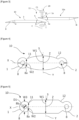
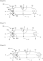
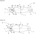
- FIG. 4], [ Figure 5 ], [ Figure 6], [ Figure 7 ], [ Figure 8 ], [ Figure 9] and [ Figure 10 ] illustrate top view of various embodiments of a bus bar element configured in accordance with the present subject matter; the description herein pertains to [ Figure 4], [ Figure 5 ], [ Figure 6], [ Figure 7 ], [ Figure 8 ], [ Figure 9] and [ Figure 10 ] in tandem for the sake of brevity.
- the main body 3 having a first portion 11 and a second portion 12 at the distal ends of the main body 3.
- the said first portion 11 and the second portion 12 integrally forms the main body 3.
- the first portion 11 and the second portion 12 converges along either side of the first axis X having a second width W2 at the distal ends of the main body 3 from where the first terminal body 1 and the second terminal body 2 extends from either side of the main body 3 along the first axis X.
- the main body 3 elongates along the second axis Y having a first width W1 in the second axis Y.
- the first width W1 of the main body 3 is greater than a cross sectional width of the first terminal body 1 and the second terminal body 2 at least along a plane normal to the first axis X.
- the bus bar element 10 may be used for the distribution of electrical power and to electrically couple plurality of electrical or electronic equipments like inverter, electric power converters, battery module, on board chargers, etc. with each other and with other components in an automobile.
- the bus bar element 10 acts as a primary component for inter connecting various battery cells in a battery module in order to get a required power output from the battery module.
- the abovementioned equipments may further be used in association with rotary electrical machines such as alternators, alternator-starters, or also reversible machines or electric motors.
- a reversible machine is a rotary electrical machine that can work reversibly, firstly as an electric generator in alternator function, and secondly as an electric motor, for instance, to start a thermal engine of a motor vehicle.
- Such rotary electrical machines may also be applied as a traction motor for hybrid or electric vehicles.
- bus bar element 10 in automotive applications, however, it can be understood that the application can extend to various other industries, such as aerospace, mining, electricity distribution, energy and power generation, etc.
Landscapes
- Chemical & Material Sciences (AREA)
- Chemical Kinetics & Catalysis (AREA)
- Electrochemistry (AREA)
- General Chemical & Material Sciences (AREA)
- Charge And Discharge Circuits For Batteries Or The Like (AREA)
- Connection Of Batteries Or Terminals (AREA)
Abstract
The present subject matter relates to a bus bar element (10) for use in automobile applications and in charging stations. The bus bar element (10) includes a first terminal body (1) that extends along a first axis (X) has a first surface (5) and a second surface (4) defining a thickness along a third axis (Z). The first terminal body (1) is configured to electrically couple with an electrical interface. A main body (3) extends from the first terminal body (1). The said first terminal boy (1) has an opening (8) that is configured to receive a fastener wherein a first thickness (T1) of the opening (8) of the first terminal body (1) extending in the first axis (X) towards the main body (3) is greater than a second thickness (T2) of at least part of the first terminal body (1) extending towards an axial end.
Description
- The present subject matter relates to a bus bar element, a bus bar system particularly for electrically coupling plurality of electrical conductive members of an electrical device preferably for automobile applications and in charging stations.
- In recent years, an automobile uses power from more than one sources, which are commonly known as hybrid vehicles. For example, a kind of hybrid vehicle uses an engine and an electric motor for propulsion which is known as Hybrid Electric Vehicle (HEV). In a non-limiting example, Electric motor alone propels the vehicle and a battery powers the electric motor. This kind of vehicles are known as Battery operated Electric Vehicle (BEV). Automobiles usually includes plurality of electrical components like cell, battery, inverter, electric power converters, battery module, on board chargers, etc. In general, in an automobile for its working, it is essential to electrically couple plurality of electrical and electronic components with each other and with other components. In case of a battery module that comprises a plurality of cells, it is mandatory to connect the individual cells using an interconnect or a terminal connector or a cell connector or a bus bar element to get the required power output for working of the automobile.
- In a known manner, the volume of such bus bar is not considered with respect to the current density. Therefore, there is a need to solve the technical problem associated with the typical bus bar element explained above.
- It is accordingly an object of the present arrangement to provide a bus bar element, to overcome the above mentioned and other disadvantages of the known arrangements.
- The present arrangement relates to a bus bar element for an electrical connection comprising: a first terminal body extending along a first axis having a first surface and a second surface defining a thickness configured to electrically couple with an electrical interface; a main body extending from the first terminal body; the said first terminal body having an opening configured to receive a fastener; wherein a first thickness of the opening of the first terminal body extending in the first axis towards the main body is greater than a second thickness of at least part of the first terminal body extending towards an axial end. Therefore, by virtue of the shape, the bus bar element is improved with different volumes with respect to different current densities throughout the bus bar element and the bus bar element with improved material usage results in material reduction.
- According to an aspect of the arrangement, a first boundary of the opening in the first axis towards the main body has the first thickness in a third axis and a second boundary of the opening in the first axis towards the axial end has the second thickness along the third axis. By virtue of different thicknesses on either side of the opening, the volume of the bus bar element is reduced thus, CO2 and production cost associated is reduced.
- According to an aspect of the arrangement, the first terminal body is sloped downward away from the main body and along the first axis. Accordingly the material is avoided to have a sloped portion of the first terminal body, as current density is low in that area thus the bus bar element is improved with different volume with respect to different current density.
- According to another aspect of the arrangement, the bus bar element is made of sheet material and defining a width along a second axis and a length along the first axis, the said first axis and the second axis are perpendicular to each other. Accordingly, the material removed from the sheet material can be recycled.
- According to yet another aspect of the arrangement, a first width of the main body is greater than a cross sectional width of the first terminal body at least along a plane normal to the first axis.
- According to an example of the arrangement, the first terminal body having a curved shape with a third width.
- According to an example of the arrangement, the first terminal body having a circular axial end with a first diameter.
- According to an example of the arrangement, the opening is a circular profile with a second diameter.
- According to an example of the arrangement, the first width of the main body extending in the second axis is at least greater than the first diameter.
- According to an example of the arrangement, the first terminal body having the opening extends along the first axis and to the axial end.
- According to yet another aspect of the arrangement, the bus bar element comprises a second terminal body extending from the main body. One advantage of using the first terminal body and the second terminal body is to interconnect two terminals for an electrical connection.
- According to yet another aspect, the present subject matter relates to a bus bar connector assembly comprising a first bus bar element in accordance with the present arrangement and a second bus bar element in accordance with the present arrangement, wherein the first surface of the first terminal body of the first bus bar element is configured to abut against a first surface of a first terminal body of the second bus bar element for electrical coupling. By virtue of which clearance required to accommodate overlapping of bus bar elements inside a casing is reduced, since overlapping of bus bar elements lies well within the thickness of the main body.
- According to yet another aspect, the present subject matter relates to a bus bar connector assembly wherein a central axis of the opening of the first terminal body of the first bus bar element coincide with a central axis of an opening of the first terminal body of the second bus bar element to receive the fastener for electrical coupling. By virtue of which a progressive current transfer takes place.
- Accordingly the bus bar element is thereby held in place and provides mechanical stability, specifically in applications where vibrations or movement is a concern.
- The current density of a bus bar element is more in the first terminal body and / or the second terminal body, at the opening adjacent to the main body. Accordingly the volume of the bus bar element is improved by having more volume in high current density regions that is in the first terminal body and / or the second terminal body, at the opening adjacent to the main body and by avoiding volume in low current density regions that is in the first terminal body and / or the second terminal body, at the opening towards the axial end along the first axis X.
- The features, aspects and advantages of the present arrangement can be better understood with reference to the following description and figures. The components in the figures are not necessarily to scale, emphasis instead being placed upon illustrating the principles of the arrangement. Moreover, in the figures, like reference numerals designate corresponding parts. In the drawings:
- [
Figure 1A ] illustrates a side view of an embodiment of a bus bar element configured in accordance with the present subject matter; - [
Figure 1B ] illustrates a side view of another embodiment of a bus bar element configured in accordance with the present subject matter; - [
Figure 2 ] illustrates top view of an embodiment of a bus bar element configured in accordance with the present subject matter; - [
Figure 3 ] illustrates a side view of a bus bar connector assembly configured in accordance with an arrangement of the present subject matter; - [
Figure 4], [Figure 5 ], [Figure 6], [Figure 7 ], [Figure 8 ], [Figure 9], and [Figure 10 ] illustrate top view of various embodiments of a bus bar element configured in accordance with the present subject matter; - The figures are not necessarily to scale, and the size of some parts may be exaggerated to more clearly illustrate the example shown. Moreover, the drawings provide examples and/or examples consistent with the description; however, the description is not limited to the examples and/or examples provided in the drawings.
- In the description that follows, reference is made to accompanying drawings, which form part thereof, and in which is shown by way of illustration specific implementations in which the invention may be practiced. These implementations are described in sufficient detail to enable that skilling in the art to practice the invention, and it is to be understood that the implementations may be combined, or that other implementations may be utilized, and that structural and logical changes may be made without departing from the scope of the present invention. The following detailed description is, therefore, not to be taken in a limiting sense, and the scope of the present invention is defined by the appended claims and their equivalents.
- The elements which are identical, similar or analogous retain the same reference from one figure to another. The ordinal numbers are used to differentiate features. They do not define a position of a feature. As a consequence, for example, a third feature of a product does not mean that the product has a first and/or a second feature.
- [
Figure 1A ] illustrates a side view of an embodiment of abus bar element 10 configured in accordance with the present subject matter. [Figure. 1B ] illustrates a side view of another embodiment of a bus bar element configured in accordance with the present subject matter. The description herein pertains to [Figure 1A] and [Figure1B ] in tandem for the sake of brevity. - The
bus bar element 10 for an electrical connection that includes a firstterminal body 1 extending along a first axis X having afirst surface 5 and asecond surface 4 defining a thickness along a third axis Z. In other word the thickness of thefirst terminal body 1 is defined by the distance between thefirst surface 5 of thefirst terminal body 1 and thesecond surface 4 of thefirst terminal body 1. The thickness of the firstterminal body 1 is not uniform. In other words the distance between thefirst surface 5 of thefirst terminal body 1 and thesecond surface 4 of thefirst terminal body 1 is not uniform. Thefirst terminal body 1 is configured to electrically couple with an electrical interface. Amain body 3 is extending from the firstterminal body 1. The firstterminal body 1 is having anopening 8. The saidfirst terminal body 1 having theopening 8 is configured to receive a fastener 20 (shown in [Figure 3 ]) wherein a first thickness T1 of the opening 8 of thefirst terminal body 1 extending in the first axis X towards themain body 3 is greater than a second thickness T2 of at least part of thefirst terminal body 1 extending towards an axial end. - [
Figure 1A ] illustrates an example where the firstterminal body 1 extends from thefirst portion 11 of themain body 3. However it is alternatively possible to have a secondterminal body 2 extending from thesecond portion 12 of themain body 3. [Figure 1B ] illustrates one such example, in which thebus bar element 10 comprises a secondterminal body 2 extending from thesecond portion 12 ofmain body 3. Accordingly, both the firstterminal body 1 and the secondterminal body 2 facilitate mounting of thebus bar element 10 to an electrical interface, and both the firstterminal body 1 and the secondterminal body 2 operate to distribute electric energy to establish an electrical connection. - In an example as illustrated in [
Figure 1B ], themain body 3 is disposed in between the firstterminal body 1 and the secondterminal body 2. The saidmain body 3 having a first surface referred as 5' and a second surface referred as 4'. The distance between the first surface 5' of themain body 3 and the second surface 4' of themain body 3 defines a thickness T4 of themain body 3. The thickness T4 of themain body 3 is for example uniform and ranging between 1mm and 10mm. Preferably the thickness T4 is between 2mm and 5mm. In one aspect, the thickness T4 of themain body 3 is greater than the first thickness T1 of theopening 8 of the firstterminal body 1. - According to [
Figure 1A] and [Figure 1B ], the firstterminal body 1 of thebus bar element 10 having afirst surface 5 and asecond surface 4 defining a thickness along a third axis Z. The firstterminal body 1 is sloped downward away from themain body 3 along the first axis X. The thickness of the firstterminal body 1 is not uniform. In other words, the distance between thefirst surface 5 of the firstterminal body 1 and thesecond surface 4 of the firstterminal body 1 is not uniform. Thefirst surface 5 of the firstterminal body 1 and thesecond surface 4 of the firstterminal body 1 are sloped or bevelled at an angle α to each other. In an aspect the angle α is between thefirst surface 5 of the firstterminal body 1 and the first axis X. Thesecond surface 4 of the firstterminal body 1 is being parallel to the first axis X and thefirst surface 5 of the firstterminal body 1 is being sloped towards the axial end along the first axis X at an angle α to the first axis X. Likewise, the secondterminal body 2 having a first surface referred as 5" and a second surface referred as 4" defining a thickness along the Z axis. The saidfirst surface 5" of the secondterminal body 2 and thesecond surface 4" of the secondterminal body 2 are sloped at an angle α as described above. Preferably the angle α takes the value between 3° and 15°. The thickness T3 of the firstterminal body 1 at the axial end along the first axis X away from themain body 3 ranges between 0.5mm and 5mm. - In yet another embodiment, the second
terminal body 2 extends from themain body 3 according to the above description in such a way that the main body is disposed between the firstterminal body 1 and the secondterminal body 2. - In one embodiment, the first thickness T1 of the
bus bar element 10 from the firstterminal body 1 towards themain body 3 is higher than the second thickness T2 of the firstterminal body 1 towards the free end. - In an exemplary embodiment as shown in [
Figure 1A] and [Figure 1B ], the firstterminal body 1 has theopening 8. Theopening 8 has a central axis C. Theopening 8 extends axially in between thefirst surface 5 of the firstterminal body 1 and thesecond surface 4 of the firstterminal body 1. In other words theopening 8 extends along the central axis C as a throughopening 8 in the firstterminal body 1. - In yet another embodiment, the second
terminal body 2 has anopening 8 according to the above description. - In an instance the
opening 8 is a circular profile complimentary to receive afastener 20 as illustrated in [Figure 1A] and [Figure 1B ]. The saidopening 8 of the firstterminal body 1 having afirst boundary 8a in the first axis X towards themain body 3 has the first thickness T1 in a third axis Z and thesecond boundary 8b of theopening 8 is in the first axis X towards the axial end of the firstterminal body 1 has the second thickness T2 along the third axis Z. - In one embodiment the first thickness T1 of the
boundary 8a of theopening 8 in the first axis X towards themain body 3 is greater than the second thickness T2 of thesecond boundary 8b of theopening 8 in the first axis X towards the axial end of the firstterminal body 1. The thickness of theopening 8 implies the distance or depth through which theopening 8 extends in between thefirst surface 5 of the firstterminal body 1 and thesecond surface 4 of the firstterminal body 1. In other words the first thickness T1 of theopening 8 is the distance or depth of theopening 8 with thefirst boundary 8a in the first axis X towards themain body 3. The second thickness T2 of theopening 8 is the distance or depth of theopening 8 with thesecond boundary 8b in the first axis X towards the axial end of the firstterminal body 1. - In one embodiments, the
opening 8 is of elliptical or elongated rounded profile. In one embodiment (not shown), theopening 8 is a circular profile and has internal threads. A threaded fastener intended to cooperate with the internal threads of theopening 8 for the fastening. - In an exemplary embodiment as illustrated in [
Figure 8 ], theopening 8 extends along the first axis X towards themain body 3 to meet thefirst boundary 8a and towards the axial end of the firstterminal body 1 as an elongated opening to meet thesecond boundary 8b. - In one embodiment the
opening 8 extends along the first axis X towards themain body 3 to meetfirst boundary 8a and towards the axial end of the firstterminal body 1 is open without thesecond boundary 8b, in other words there is nosecond boundary 8b as illustrated in [Figure 4 ], [Figure 7 ] and [Figure 9 ]. - In an instance the
second boundary 8b is introduced (not shown) in the embodiments as shown in [Figure 4 ], [Figure 7 ] and [Figure 9 ] by welding to accept the torque of thefastener 20 tightening. - In one embodiment the
fastener 20 is a bolt and nut with washer (not shown) as illustrated in [Figure 3 ]. The washer (not shown) is used to give a better grasp for holding the flat surface of the nut and the flange of the bolt on the sloped surface of the firstterminal body 1 and the secondterminal body 2 of thebus bar element 10. - In a non-limiting manner, the
opening 8 of thebus bar element 10 is configured to be fastened with the various electrical or electronic equipments or another bus bar element as stated in the further description below by means of thefastener 20 inserted through theopening 8. A mounting includes direct mounting either by bolting or by welding as a non limiting examples. - [
Figure 2 ] illustrates a top view of an embodiment of abus bar element 10 configured in accordance with the present subject matter. - In an embodiment, the
bus bar element 10 is made of sheet material and defining a width along a second axis Y and a length along the first axis X. The first axis X and the second axis Y are perpendicular to each other. - In an embodiment as shown in [
Figure 2 ], themain body 3 having two distal ends opposite to each other along the first axis X. Themain body 3 having afirst portion 11 and asecond portion 12 at the distal ends of themain body 3. The firstterminal body 1 and/or the secondterminal body 2 has a curved shape with a cross sectional third width W3. The cross sectional third width W3 is measured between the axial end of the firstterminal body 2 and thefirst portion 11 of themain body 3. The cross sectional third width W3 is also measured between the axial end of the secondterminal body 3 and thesecond portion 12 of themain body 3. The saidfirst portion 11 andsecond portion 12 integrally forms themain body 3 extending from the firstterminal body 1 and/or the secondterminal body 2. Thefirst portion 11 and thesecond portion 12 converges along either side of the first axis X. The width of the boundary between firstterminal body 1 or secondterminal body 2 and themain body 3 is a second width W2. Themain body 3 elongates along the second axis Y having a first width W1 in the second axis Y. The first width W1 of themain body 3 is greater than the cross sectional third width W3 of the firstterminal body 1 and or secondterminal body 2 at least along a plane normal to the first axis X. - In an exemplary embodiment as illustrated in [
Figure 2 ] the firstterminal body 1 and the secondterminal body 2 has a circular axial ends with a first diameter D2. Further the firstterminal body 1 and the secondterminal body 2 has theopening 8. Theopening 8 is a circular opening with a second diameter D1. The range of the diameter D1 is between 4mm and 12mm, preferably between 6mm and 10mm. The first diameter D2 is given by the expression D2=D1 + (2*T4). Preferably, the range of the first diameter D2 is between 6mm and 32mm. The second diameter D1 of theopening 8 is in compliment with the bolt diameter of thefastener 20. Preferably, the first diameter D2 is greater than the second width W2 but not greater than the first width W1. - The said first width W1 is greater than the second width W2 and the third width W3. The first width W1 of the
main body 3 extending in the second axis Y is at least greater than the first diameter D2. Preferably, the range of the first width W1 is between 10mm and 34mm. Preferably, the range of the second width W2 is between 6mm and 16mm. - In an embodiment, the
main body 3 has a non-uniform thickness with maximum thickness extending in the third axis Z and reduces towards thefirst portion 11 and / orsecond portion 12 of themain body 3 along the first axis X. - [
Figure 3 ] illustrates a side view of a busbar connector assembly 11 configured in accordance with an arrangement of the present subject matter. A busbar connector assembly 11 comprising a firstbus bar element 10 configured in accordance with the present subject matter as described above and a secondbus bar element 10a configured in accordance with the present subject matter as described above. Thefirst surface 5 of the firstterminal body 1 of the firstbus bar element 10 is abutting against afirst surface 5a of a firstterminal body 1a of the secondbus bar element 10a for electrical coupling. - In a non - limiting example a central axis C of the
opening 8 of the firstterminal body 1 of the firstbus bar element 10 substantially coincides with a central axis C1 of anopening 8 of the firstterminal body 1a of the secondbus bar element 10a. - The first
bus bar element 10 and the secondbus bar element 10a are coupled together by afastener 20 for electrical coupling as illustrated in [Figure 3 ]. - In an instance, the first
terminal body 1 of thebus bar element 10 is configured to mechanically and electrically couple to a conducting element or an electrical or electronic equipments. For instance, the conducting element may be a secondbus bar element 10a whose correspondingterminal body 1a is configured in accordance with the present subject matter as illustrated in [Figure 3 ]. Likewise, in a non-limiting manner more number of bus bar elements in accordance with the present subject matter is coupled in an above described examples. - [
Figure 4], [Figure 5 ], [Figure 6], [Figure 7 ], [Figure 8 ], [Figure 9] and [Figure 10 ] illustrate top view of various embodiments of a bus bar element configured in accordance with the present subject matter; the description herein pertains to [Figure 4], [Figure 5 ], [Figure 6], [Figure 7 ], [Figure 8 ], [Figure 9] and [Figure 10 ] in tandem for the sake of brevity. - According to an aspect of the present subject matter, the
main body 3 having afirst portion 11 and asecond portion 12 at the distal ends of themain body 3. The saidfirst portion 11 and thesecond portion 12 integrally forms themain body 3. Thefirst portion 11 and thesecond portion 12 converges along either side of the first axis X having a second width W2 at the distal ends of themain body 3 from where the firstterminal body 1 and the secondterminal body 2 extends from either side of themain body 3 along the first axis X. Themain body 3 elongates along the second axis Y having a first width W1 in the second axis Y. The first width W1 of themain body 3 is greater than a cross sectional width of the firstterminal body 1 and the secondterminal body 2 at least along a plane normal to the first axis X. - The
bus bar element 10 may be used for the distribution of electrical power and to electrically couple plurality of electrical or electronic equipments like inverter, electric power converters, battery module, on board chargers, etc. with each other and with other components in an automobile. Thebus bar element 10 acts as a primary component for inter connecting various battery cells in a battery module in order to get a required power output from the battery module. In a non-limiting example, the abovementioned equipments may further be used in association with rotary electrical machines such as alternators, alternator-starters, or also reversible machines or electric motors. A reversible machine is a rotary electrical machine that can work reversibly, firstly as an electric generator in alternator function, and secondly as an electric motor, for instance, to start a thermal engine of a motor vehicle. Such rotary electrical machines may also be applied as a traction motor for hybrid or electric vehicles. - The present subject matter speaks of applying the
bus bar element 10 in automotive applications, however, it can be understood that the application can extend to various other industries, such as aerospace, mining, electricity distribution, energy and power generation, etc. - Various modifications of the disclosed embodiments, as well as alternate embodiments of the subject matter, will become apparent to persons skilled in the art upon reference to the description of the subject matter. It is therefore contemplated that such modifications can be made without departing from the scope of the present subject matter is defined.
Claims (13)
- Bus bar element (10) for an electrical connection comprising: a first terminal body (1) extending along a first axis (X) having a first surface (5) and a second surface (4) defining a thickness along a third axis (Z) configured to electrically couple with an electrical interface; a main body (3) extending from the first terminal body (1); the said first terminal body (1) having an opening (8) configured to receive a fastener (20); wherein a first thickness (T1) of the opening (8) of the first terminal body (1) extending in the first axis (X) towards the main body (3) is greater than a second thickness (T2) of at least part of the first terminal body (1) extending towards an axial end.
- Bus bar element (10) according to claim 1, wherein a first boundary (8a) of the opening (8) in the first axis (X) towards the main body (3) has the first thickness (T1) in a third axis (Z) and a second boundary (8b) of the opening (8) in the first axis (X) towards the axial end has the second thickness (T2) along the third axis (Z)
- Bus bar element (10) according to any one of the claims 1 to 2, wherein the first terminal body (1) is sloped downward away from the main body (3).
- Bus bar element (10) according to any one of the claims 1 to 3, wherein the bus bar element (10) is made of sheet material defining a width along a second axis (Y) and a length along the first axis (X), the said first axis (X) and the second axis (Y) are perpendicular to each other.
- Bus bar element (10) according to any one of the claims 1 to 4, wherein a first width (W1) of the main body (3) is greater than a cross sectional width of the first terminal body (1) at least along a plane normal to the first axis (X).
- Bus bar element (10) according to any one of the claims 1 to 5, wherein the first terminal body (1) having a curved shape with a third width (W3).
- Bus bar element (10) according to claim 6, wherein the first terminal body (1) having a circular axial end with a first diameter (D2).
- Bus bar element (10) according to any one of the claim 1 to 7, wherein the opening (8) is a circular profile with a second diameter (D1).
- Bus bar element (10) as claimed in claim 7 in combination with claim 4 and 5, wherein the first width (W1) of the main body (3) extending in the second axis (Y) is at least greater than the first diameter (D2).
- Bus bar element (10) according to any one of the claims 1 to 9, wherein the first terminal body (1) having the opening (8) extending along the first axis (X) and to the axial end.
- Bus bar element (10) in accordance with any one of the claim 1 to 10, wherein the bus bar element (10) comprises a second terminal body (2) extending from the main body (3).
- Bus bar connector assembly (11) comprising a first bus bar element (10) in accordance with any one of the claim 1 to 11 and a second bus bar element (10a) in accordance with any one of the claim 1 to 11, wherein the first surface (5) of the first terminal body (1) of the first bus bar element (10) is configured to abut against a first surface (5a) of a first terminal body (1a) of the second bus bar element (10a) for electrical coupling.
- Bus bar connector assembly (11) as claimed in claim 12, wherein a central axis (C) of the opening (8) of the first terminal body (1) of the first bus bar element (10) substantially coincides with a central axis (C1) of an opening (8i) of the first terminal body (1a) of the second bus bar element (10a) to receive the fastener (20) for electrical coupling.
Applications Claiming Priority (1)
| Application Number | Priority Date | Filing Date | Title |
|---|---|---|---|
| FR2315324A FR3157694A1 (en) | 2023-12-26 | 2023-12-26 | Bus bar element |
Publications (1)
| Publication Number | Publication Date |
|---|---|
| EP4579969A1 true EP4579969A1 (en) | 2025-07-02 |
Family
ID=89897699
Family Applications (1)
| Application Number | Title | Priority Date | Filing Date |
|---|---|---|---|
| EP24220382.6A Pending EP4579969A1 (en) | 2023-12-26 | 2024-12-16 | A busbar element |
Country Status (4)
| Country | Link |
|---|---|
| EP (1) | EP4579969A1 (en) |
| KR (1) | KR20250100535A (en) |
| CN (1) | CN120221932A (en) |
| FR (1) | FR3157694A1 (en) |
Citations (4)
| Publication number | Priority date | Publication date | Assignee | Title |
|---|---|---|---|---|
| EP1014494A1 (en) * | 1998-12-16 | 2000-06-28 | Zurecon Ag | Method for connecting metallic current conductors and an electrical busbar connection made by the method |
| CN104862743A (en) * | 2015-06-19 | 2015-08-26 | 成都福凌云科技有限公司 | Busbar connection structure and method for reducing connected high current busbar contact voltage |
| RU174019U1 (en) * | 2017-02-10 | 2017-09-26 | Сергей Валентинович Воронин | LAYOUT JOINT SECTION OF THE MAIN BUSBAR |
| DE102019007400A1 (en) * | 2018-11-28 | 2020-05-28 | Sew-Eurodrive Gmbh & Co. Kg | Drive system |
-
2023
- 2023-12-26 FR FR2315324A patent/FR3157694A1/en active Pending
-
2024
- 2024-12-16 EP EP24220382.6A patent/EP4579969A1/en active Pending
- 2024-12-18 KR KR1020240190153A patent/KR20250100535A/en active Pending
- 2024-12-20 CN CN202411887258.8A patent/CN120221932A/en active Pending
Patent Citations (4)
| Publication number | Priority date | Publication date | Assignee | Title |
|---|---|---|---|---|
| EP1014494A1 (en) * | 1998-12-16 | 2000-06-28 | Zurecon Ag | Method for connecting metallic current conductors and an electrical busbar connection made by the method |
| CN104862743A (en) * | 2015-06-19 | 2015-08-26 | 成都福凌云科技有限公司 | Busbar connection structure and method for reducing connected high current busbar contact voltage |
| RU174019U1 (en) * | 2017-02-10 | 2017-09-26 | Сергей Валентинович Воронин | LAYOUT JOINT SECTION OF THE MAIN BUSBAR |
| DE102019007400A1 (en) * | 2018-11-28 | 2020-05-28 | Sew-Eurodrive Gmbh & Co. Kg | Drive system |
Also Published As
| Publication number | Publication date |
|---|---|
| FR3157694A1 (en) | 2025-06-27 |
| KR20250100535A (en) | 2025-07-03 |
| CN120221932A (en) | 2025-06-27 |
Similar Documents
| Publication | Publication Date | Title |
|---|---|---|
| EP3916897B1 (en) | Battery pack casing, battery pack and vehicle | |
| JP5549401B2 (en) | Battery pack and connection method between electrode terminals | |
| US10128722B2 (en) | Electrical connection structure, terminal structure, and vehicle | |
| CN102893457B (en) | Electric cable and electric connector | |
| US11851012B2 (en) | Flexible bus bar | |
| CN113447822B (en) | Measuring assembly for measuring temperature and voltage | |
| WO2011043121A1 (en) | Terminal block | |
| KR102029370B1 (en) | Charger inlet for electric vehicle with improved earth structure | |
| US12155163B2 (en) | Bus bar and wire harness | |
| US20250192310A1 (en) | Traction battery pack structural cross-member assemblies with tensile and compression load carrying capability | |
| EP4579969A1 (en) | A busbar element | |
| US20110001355A1 (en) | Power subassembly for micro-hybrid system in an automobile | |
| KR102615842B1 (en) | Contact spring for connector of electric veheicle and connector of electric veheicle having the same | |
| KR20230065092A (en) | Connector module and Converter having the same | |
| KR102515174B1 (en) | Power terminal module | |
| WO2025082843A1 (en) | A composite bus bar for an electric device | |
| KR102792357B1 (en) | Angle terminal for inlet | |
| WO2017077025A1 (en) | Vehicle earth point connector | |
| US20240123924A1 (en) | High Voltage Connector for Vehicle | |
| US20250350197A1 (en) | Systems and methods for voltage conversion | |
| US20250279598A1 (en) | Flexible HV Connector Busbar Interconnect System | |
| US20250202139A1 (en) | Connector | |
| KR20230090276A (en) | Battery module and battery pack and vehicle including the same | |
| US20260005451A1 (en) | Electrical connector, electric drive unit and vehicle | |
| US20250233287A1 (en) | Battery cell tab shape variations for optimizing battery cell-to-busbar electrical connections |
Legal Events
| Date | Code | Title | Description |
|---|---|---|---|
| PUAI | Public reference made under article 153(3) epc to a published international application that has entered the european phase |
Free format text: ORIGINAL CODE: 0009012 |
|
| STAA | Information on the status of an ep patent application or granted ep patent |
Free format text: STATUS: EXAMINATION IS IN PROGRESS |
|
| 17P | Request for examination filed |
Effective date: 20241216 |
|
| AK | Designated contracting states |
Kind code of ref document: A1 Designated state(s): AL AT BE BG CH CY CZ DE DK EE ES FI FR GB GR HR HU IE IS IT LI LT LU LV MC ME MK MT NL NO PL PT RO RS SE SI SK SM TR |