EP4579957A1 - Connector assembly - Google Patents
Connector assembly Download PDFInfo
- Publication number
- EP4579957A1 EP4579957A1 EP24209705.3A EP24209705A EP4579957A1 EP 4579957 A1 EP4579957 A1 EP 4579957A1 EP 24209705 A EP24209705 A EP 24209705A EP 4579957 A1 EP4579957 A1 EP 4579957A1
- Authority
- EP
- European Patent Office
- Prior art keywords
- substrate
- portions
- fixed member
- contact
- connector assembly
- Prior art date
- Legal status (The legal status is an assumption and is not a legal conclusion. Google has not performed a legal analysis and makes no representation as to the accuracy of the status listed.)
- Granted
Links
Images









Classifications
-
- H—ELECTRICITY
- H01—ELECTRIC ELEMENTS
- H01R—ELECTRICALLY-CONDUCTIVE CONNECTIONS; STRUCTURAL ASSOCIATIONS OF A PLURALITY OF MUTUALLY-INSULATED ELECTRICAL CONNECTING ELEMENTS; COUPLING DEVICES; CURRENT COLLECTORS
- H01R13/00—Details of coupling devices of the kinds covered by groups H01R12/70 or H01R24/00 - H01R33/00
- H01R13/40—Securing contact members in or to a base or case; Insulating of contact members
-
- H—ELECTRICITY
- H01—ELECTRIC ELEMENTS
- H01R—ELECTRICALLY-CONDUCTIVE CONNECTIONS; STRUCTURAL ASSOCIATIONS OF A PLURALITY OF MUTUALLY-INSULATED ELECTRICAL CONNECTING ELEMENTS; COUPLING DEVICES; CURRENT COLLECTORS
- H01R12/00—Structural associations of a plurality of mutually-insulated electrical connecting elements, specially adapted for printed circuits, e.g. printed circuit boards [PCB], flat or ribbon cables, or like generally planar structures, e.g. terminal strips, terminal blocks; Coupling devices specially adapted for printed circuits, flat or ribbon cables, or like generally planar structures; Terminals specially adapted for contact with, or insertion into, printed circuits, flat or ribbon cables, or like generally planar structures
- H01R12/70—Coupling devices
- H01R12/7005—Guiding, mounting, polarizing or locking means; Extractors
- H01R12/7011—Locking or fixing a connector to a PCB
- H01R12/7047—Locking or fixing a connector to a PCB with a fastener through a screw hole in the coupling device
-
- H—ELECTRICITY
- H01—ELECTRIC ELEMENTS
- H01R—ELECTRICALLY-CONDUCTIVE CONNECTIONS; STRUCTURAL ASSOCIATIONS OF A PLURALITY OF MUTUALLY-INSULATED ELECTRICAL CONNECTING ELEMENTS; COUPLING DEVICES; CURRENT COLLECTORS
- H01R13/00—Details of coupling devices of the kinds covered by groups H01R12/70 or H01R24/00 - H01R33/00
- H01R13/02—Contact members
-
- H—ELECTRICITY
- H01—ELECTRIC ELEMENTS
- H01R—ELECTRICALLY-CONDUCTIVE CONNECTIONS; STRUCTURAL ASSOCIATIONS OF A PLURALITY OF MUTUALLY-INSULATED ELECTRICAL CONNECTING ELEMENTS; COUPLING DEVICES; CURRENT COLLECTORS
- H01R13/00—Details of coupling devices of the kinds covered by groups H01R12/70 or H01R24/00 - H01R33/00
- H01R13/648—Protective earth or shield arrangements on coupling devices, e.g. anti-static shielding
-
- H—ELECTRICITY
- H01—ELECTRIC ELEMENTS
- H01R—ELECTRICALLY-CONDUCTIVE CONNECTIONS; STRUCTURAL ASSOCIATIONS OF A PLURALITY OF MUTUALLY-INSULATED ELECTRICAL CONNECTING ELEMENTS; COUPLING DEVICES; CURRENT COLLECTORS
- H01R24/00—Two-part coupling devices, or either of their cooperating parts, characterised by their overall structure
- H01R24/38—Two-part coupling devices, or either of their cooperating parts, characterised by their overall structure having concentrically or coaxially arranged contacts
- H01R24/40—Two-part coupling devices, or either of their cooperating parts, characterised by their overall structure having concentrically or coaxially arranged contacts specially adapted for high frequency
-
- H—ELECTRICITY
- H01—ELECTRIC ELEMENTS
- H01R—ELECTRICALLY-CONDUCTIVE CONNECTIONS; STRUCTURAL ASSOCIATIONS OF A PLURALITY OF MUTUALLY-INSULATED ELECTRICAL CONNECTING ELEMENTS; COUPLING DEVICES; CURRENT COLLECTORS
- H01R24/00—Two-part coupling devices, or either of their cooperating parts, characterised by their overall structure
- H01R24/38—Two-part coupling devices, or either of their cooperating parts, characterised by their overall structure having concentrically or coaxially arranged contacts
- H01R24/40—Two-part coupling devices, or either of their cooperating parts, characterised by their overall structure having concentrically or coaxially arranged contacts specially adapted for high frequency
- H01R24/50—Two-part coupling devices, or either of their cooperating parts, characterised by their overall structure having concentrically or coaxially arranged contacts specially adapted for high frequency mounted on a PCB [Printed Circuit Board]
-
- H—ELECTRICITY
- H01—ELECTRIC ELEMENTS
- H01R—ELECTRICALLY-CONDUCTIVE CONNECTIONS; STRUCTURAL ASSOCIATIONS OF A PLURALITY OF MUTUALLY-INSULATED ELECTRICAL CONNECTING ELEMENTS; COUPLING DEVICES; CURRENT COLLECTORS
- H01R9/00—Structural associations of a plurality of mutually-insulated electrical connecting elements, e.g. terminal strips or terminal blocks; Terminals or binding posts mounted upon a base or in a case; Bases therefor
- H01R9/03—Connectors arranged to contact a plurality of the conductors of a multiconductor cable, e.g. tapping connections
- H01R9/05—Connectors arranged to contact a plurality of the conductors of a multiconductor cable, e.g. tapping connections for coaxial cables
- H01R9/0515—Connection to a rigid planar substrate, e.g. printed circuit board
-
- H—ELECTRICITY
- H01—ELECTRIC ELEMENTS
- H01R—ELECTRICALLY-CONDUCTIVE CONNECTIONS; STRUCTURAL ASSOCIATIONS OF A PLURALITY OF MUTUALLY-INSULATED ELECTRICAL CONNECTING ELEMENTS; COUPLING DEVICES; CURRENT COLLECTORS
- H01R9/00—Structural associations of a plurality of mutually-insulated electrical connecting elements, e.g. terminal strips or terminal blocks; Terminals or binding posts mounted upon a base or in a case; Bases therefor
- H01R9/03—Connectors arranged to contact a plurality of the conductors of a multiconductor cable, e.g. tapping connections
- H01R9/05—Connectors arranged to contact a plurality of the conductors of a multiconductor cable, e.g. tapping connections for coaxial cables
- H01R9/0527—Connection to outer conductor by action of a resilient member, e.g. spring
-
- H—ELECTRICITY
- H01—ELECTRIC ELEMENTS
- H01R—ELECTRICALLY-CONDUCTIVE CONNECTIONS; STRUCTURAL ASSOCIATIONS OF A PLURALITY OF MUTUALLY-INSULATED ELECTRICAL CONNECTING ELEMENTS; COUPLING DEVICES; CURRENT COLLECTORS
- H01R12/00—Structural associations of a plurality of mutually-insulated electrical connecting elements, specially adapted for printed circuits, e.g. printed circuit boards [PCB], flat or ribbon cables, or like generally planar structures, e.g. terminal strips, terminal blocks; Coupling devices specially adapted for printed circuits, flat or ribbon cables, or like generally planar structures; Terminals specially adapted for contact with, or insertion into, printed circuits, flat or ribbon cables, or like generally planar structures
- H01R12/70—Coupling devices
- H01R12/7005—Guiding, mounting, polarizing or locking means; Extractors
- H01R12/7011—Locking or fixing a connector to a PCB
- H01R12/7052—Locking or fixing a connector to a PCB characterised by the locating members
-
- H—ELECTRICITY
- H01—ELECTRIC ELEMENTS
- H01R—ELECTRICALLY-CONDUCTIVE CONNECTIONS; STRUCTURAL ASSOCIATIONS OF A PLURALITY OF MUTUALLY-INSULATED ELECTRICAL CONNECTING ELEMENTS; COUPLING DEVICES; CURRENT COLLECTORS
- H01R12/00—Structural associations of a plurality of mutually-insulated electrical connecting elements, specially adapted for printed circuits, e.g. printed circuit boards [PCB], flat or ribbon cables, or like generally planar structures, e.g. terminal strips, terminal blocks; Coupling devices specially adapted for printed circuits, flat or ribbon cables, or like generally planar structures; Terminals specially adapted for contact with, or insertion into, printed circuits, flat or ribbon cables, or like generally planar structures
- H01R12/70—Coupling devices
- H01R12/71—Coupling devices for rigid printing circuits or like structures
- H01R12/72—Coupling devices for rigid printing circuits or like structures coupling with the edge of the rigid printed circuits or like structures
- H01R12/722—Coupling devices for rigid printing circuits or like structures coupling with the edge of the rigid printed circuits or like structures coupling devices mounted on the edge of the printed circuits
-
- H—ELECTRICITY
- H01—ELECTRIC ELEMENTS
- H01R—ELECTRICALLY-CONDUCTIVE CONNECTIONS; STRUCTURAL ASSOCIATIONS OF A PLURALITY OF MUTUALLY-INSULATED ELECTRICAL CONNECTING ELEMENTS; COUPLING DEVICES; CURRENT COLLECTORS
- H01R2103/00—Two poles
Definitions
- This invention relates to a connector assembly which is configured to be connected to a substrate.
- JPB 6853655 discloses a connector assembly which is configured to be connected to a substrate.
- a substrate-connector connection structure 900 of Patent Document 1 has a substrate 950 and a connector 910, or a connector assembly 910. Specifically, the connector assembly 910 is connected to the substrate 950.
- the substrate 950 has a signal pattern 952, or a signal line 952, a first ground layer 954 and a plating layer 956. Specifically, the plating layer 956 is located just below the signal line 952 and is formed at a region including an end surface of the first ground layer 954.
- the connector assembly 910 comprises a coaxial connector 920 and two screws 930, or fixing members 930.
- the coaxial connector 920 has a center conductor 922, or a center terminal 922, and an outer conductor 924, or an outer terminal 924.
- the outer terminal 924 is brought into contact with the plating layer 956 which is electrically connected to the first ground layer 954.
- the substrate-connector connection structure 900 of Patent Document 1 is configured to reduce reflection characteristics of signal propagating between the substrate 950 and the connector assembly 910.
- the substrate-connector connection structure 900 of Patent Document 1 it is difficult for the outer terminal 924 of the coaxial connector 920 to be stably connected to the plating layer 956 of the substrate 950 when the connector assembly 910 is connected to the substrate 950. Accordingly, the substrate-connector connection structure 900 of Patent Document 1 might not make a reliable electrical connection between the outer terminal 924 and the first ground layer 954.
- One aspect of the present invention provides a connector assembly configured to be connected to a substrate.
- the substrate is formed with two passing holes. Each of the passing holes passes through the substrate in an up-down direction.
- the substrate has an upper surface and a lower surface in the up-down direction.
- the upper surface of the substrate is formed with a signal line.
- the signal line is located between the two passing holes in a lateral direction perpendicular to the up-down direction.
- the lower surface of the substrate is formed with a ground layer.
- the connector assembly comprises a coaxial connector, a fixed member and two fixing members.
- the coaxial connector is configured to be attached to a distal end of a coaxial cable.
- the coaxial connector comprises an outer terminal and a center terminal. The outer terminal has a flange portion and two projecting portions.
- the flange portion has a first receiving portion and two second receiving portions.
- the first receiving portion faces forward in a front-rear direction perpendicular to both the up-down direction and the lateral direction.
- Each of the two second receiving portions faces at least rearward in the front-rear direction.
- the two projecting portions are apart from each other in the lateral direction.
- Each of the two projecting portions extends forward in the front-rear direction from the flange portion.
- the fixed member is made of metal.
- the fixed member is located below the substrate in the up-down direction under a connected state where the connector assembly is connected to the substrate.
- the ground layer of the substrate is electrically connected to the first receiving portion of the flange portion via the fixed member under the connected state.
- the fixed member has a main portion, a first contact portion, at least one spring portion and two second contact portions.
- the main portion extends in a predetermined plane.
- the first contact portion is provided at the main portion.
- the first contact portion is located, at least in part, between the two second contact portions.
- the spring portion extends from the main portion and is resiliently deformable.
- the two second contact portions are apart from each other in the lateral direction. At least one of the two second contact portions is supported by the spring portion and is movable in the predetermined plane. Under the connected state, the spring portion presses the second contact portion against the second receiving portion while the second contact portion receives reaction force from the second receiving portion by the pressing of the spring portion.
- the first contact portion is pressed against the first receiving portion along the front-rear direction by the reaction force under the connected state.
- the two fixing members are fixed to the two projecting portions of the outer terminal through the two passing holes, respectively, of the substrate while the two fixing members press the fixed member against the ground layer of the substrate so that the predetermined plane becomes perpendicular to the up-down direction.
- the connector assembly of the present invention is configured as follows: under the connected state where the connector assembly is connected to the substrate, the spring portion presses the second contact portion against the second receiving portion while the second contact portion receives the reaction force from the second receiving portion by the pressing of the spring portion; and the first contact portion is pressed against the first receiving portion along the front-rear direction by the reaction force under the connected state. Accordingly, the connector assembly of the present invention is configured so that the fixed member is securely connected to the outer terminal of the coaxial connector.
- the ground layer of the substrate is electrically connected to the first receiving portion of the flange portion of the outer terminal via the fixed member in a highly reliable manner when the connector assembly of the present invention is connected to the substrate.
- the connector assembly of the present invention enables the outer terminal of the coaxial connector of the connector assembly to be stably connected to the ground layer of the substrate.
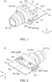
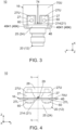
- a structure 10 according to an embodiment of the present invention comprises a connector assembly 12 and a substrate 16.
- the substrate 16 extends along a horizontal plane.
- the connector assembly 12 is configured to be connected to the substrate 16.
- the connector assembly 12 is configured to be connected to a rear end portion of the substrate 16 in a front-rear direction parallel to the horizontal plane.
- the connector assembly 12 of each of Figs. 1 to 7 is under a connected state where the connector assembly 12 is connected to the substrate 16.
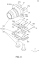
- the connector assembly 12 of each of Figs. 8 and 9 is under a pre-connected state where the connector assembly 12 is not yet connected to the substrate 16.
- the horizontal plane of the present embodiment is an XY-plane.
- the front-rear direction of the present embodiment is an X-direction.
- "forward” means a positive X-direction
- "rearward” means a negative X-direction.
- the words such as the horizontal plane and the front-rear direction do not indicate the absolute positional relation relative to the ground but merely indicate a relative positional relation under a definition where the substrate 16 extends in the horizontal plane and where the connector assembly 12 is located rearward of this substrate 16.
- the substrate 16 is not specifically limited. Specifically, the substrate 16 may be a flexible board, or may be a rigid substrate.
- the substrate 16 has an upper surface 70U and a lower surface 70L in an up-down direction perpendicular to the horizontal plane.
- the upper surface 70U and the lower surface 70L are located at an upper end and a lower end of a base 70, respectively.
- the up-down direction of the present embodiment is a Z-direction.
- "upward” means a positive Z-direction
- "downward” means a negative Z-direction.
- the substrate 16 is formed with two passing holes 72.
- Each of the passing holes 72 passes through the substrate 16 in the up-down direction.
- Each of the passing holes 72 has a circular shape in the horizontal plane.
- the thus-formed passing holes 72 are used when the connector assembly 12 is screwed to the substrate 16 as described later.
- the two passing holes 72 are apart from each other in a lateral direction perpendicular to both the front-rear direction and the up-down direction and are located at positions same as each other in the front-rear direction.
- the lateral direction of the present embodiment is a Y-direction.
- the lateral direction is also referred to as a right-left direction.
- "rightward” means a positive Y-direction
- “leftward” means a negative Y-direction.
- the passing holes 72 of the present embodiment are formed as described above. However, the present invention is not limited thereto.
- the shape of each of the passing holes 72 is not specifically limited.
- the number of the passing holes 72 may be three or more. In this instance, two of the passing holes 72 may be apart from each other in the lateral direction and may be located at positions same as each other in the front-rear direction.
- the upper surface 70U of the substrate 16 is formed with a signal line 74 which is a conductive pattern.
- the signal line 74 extends in the front-rear direction and is located between the two passing holes 72 in the lateral direction.
- the signal line 74 of an instance is connected to an antenna which is formed on an unillustrated front end part of the substrate 16.
- the connector assembly 12 under the connected state transmits signals to the antenna through the signal line 74.
- the thus-transmitted signals are sent outward from the antenna.
- signals received by the antenna are transmitted to the connector assembly 12 through the signal line 74.
- the structure 10 of the present embodiment is uses as described above, for example.
- the structure 10 of the present embodiment is an antenna device.
- the usage of the structure 10 of the present invention is not specifically limited.
- the structure 10 of the present invention may be any electric device with the substrate 16.
- the connector assembly 12 of the present embodiment comprises a coaxial connector 20, a fixed member 40 and two fixing members 60, or two screws 60.
- the connector assembly 12 of the present embodiment comprises only the aforementioned members.
- the present invention is not limited thereto.
- the connector assembly 12 may further comprise another member in addition to the aforementioned members.
- the coaxial cable 80 illustrated with dashed line is a typical coaxial cable and comprises a center conductor 82 made of conductor, an inner insulator 84 made of insulator and covering the center conductor 82, an outer conductor 86 made of conductor and covering the inner insulator 84 and a sheath 88 made of insulator and covering the outer conductor 86.
- the number of the center conductor 82 of the present embodiment is one.
- the configuration of the coaxial connector 20 is not specifically limited, provided that the number of the center conductor 82 is one.
- the outer conductor 86 may be a braid formed of fine metal wires or may be made of metal foil.
- the coaxial cable 80 may be connected to a rear end of the coaxial connector 20 via a mating connector 89 attached to the coaxial cable 80.
- the coaxial connector 20 of the present embodiment comprises a center terminal 21 made of metal and an outer terminal 24 made of metal.
- the center terminal 21 of the present embodiment extends along the front-rear direction and has a body 212, a contact portion 214 and a connection portion 218.
- the body 212 is a middle part of the center terminal 21 in the front-rear direction.
- the contact portion 214 extends forward from the body 212.
- the contact portion 214 is bent downward in the up-down direction after the coaxial connector 20 is assembled. Specifically, the contact portion 214 extends forward and downward under a pre-connected state where the connector assembly 12 is not yet connected to the substrate 16.
- the contact portion 214 defines a front end of the center terminal 21 in the front-rear direction. As shown in Fig.
- connection portion 218 has a socket shape and extends rearward from the body 212.
- the connection portion 218 defines a rear end of the center terminal 21 in the front-rear direction.
- the center terminal 21 is connected with the center conductor 82 of the coaxial cable 80 when the coaxial connector 20 is attached to the coaxial cable 80.
- the connection portion 218 of the center terminal 21 is configured to be electrically connected with the center conductor 82.
- the center terminal 21 and the center conductor 82 connected to each other transmit signals to each other.
- the center terminal 21 of the present embodiment has the aforementioned configuration.
- the configuration of the center terminal 21 can be modified as necessary, provided that the center terminal 21 has the contact portion 214 which extends along the front-rear direction.
- the outer terminal 24 of the present embodiment comprises a front conductive member 242 and a rear conductive member 244.
- the front conductive member 242 is combined with the rear conductive member 244 and is located forward of the rear conductive member 244.
- the front conductive member 242 is in contact with the rear conductive member 244.
- the outer terminal 24 of the present embodiment consists of the aforementioned two members.
- the present invention is not limited thereto.
- the front conductive member 242 and the rear conductive member 244 may be a member integrally formed with each other.
- the outer terminal 24 is electrically connected with the outer conductor 86 of the coaxial cable 80 when the coaxial connector 20 is attached to the coaxial cable 80.
- the rear conductive member 244 of the outer terminal 24 is configured to be electrically connected with the outer conductor 86.
- the outer terminal 24 and the outer conductor 86 connected to each other have ground potentials same as each other.
- the outer terminal 24 has a flange portion 25 and two projecting portions 27.
- the flange portion 25 of the present embodiment has a first receiving portion 252 and two second receiving portions 254.
- the first receiving portion 252 faces forward in the front-rear direction perpendicular to both the up-down direction and the lateral direction.
- the first receiving portion 252 is located around a middle of the flange portion 25 in the up-down direction.
- the first receiving portion 252 is located at a middle of the flange portion 25 in the lateral direction.
- the ground layer 78A of the substrate 16 is electrically connected to the first receiving portion 252 of the flange portion 25 via the fixed member 40.
- each of the two second receiving portions 254 faces rearward in the front-rear direction.
- the second receiving portion 254 may face rearward in the front-rear direction and outward in the lateral direction. In other words, each of the two second receiving portions 254 should face at least rearward in the front-rear direction.
- the second receiving portions 254 are located at opposite ends, respectively, of the flange portion 25 in the lateral direction.
- the first receiving portion 252 is located forward of any of the second receiving portions 254 in the front-rear direction.
- the first receiving portion 252 may be located rearward of the second receiving portion 254 in the front-rear direction, provided that the first receiving portion 252 faces forward while the second receiving portion 254 faces at least rearward. If the first receiving portion 252 and the second receiving portions 254 are configured similar to the present embodiment, the flange portion 25 can have a reduced size in the front-rear direction. Accordingly, the first receiving portion 252 and the second receiving portions 254 of the present embodiment are more preferable.
- the flange portion 25 has a second distance D2 between the first receiving portion 252 and any of the second receiving portions 254 in the front-rear direction.
- the flange portion 25 of the present embodiment has two guide portions 256.
- Each of the guide portion 256 is oblique to both the front-rear direction and the up-down direction.
- the guide portion 256 is located below the second receiving portion 254 in the up-down direction.
- the guide portions 256 correspond to the second receiving portions 254, respectively.
- Each of the guide portions 256 is located below the corresponding second receiving portion 254 in the up-down direction.
- the two projecting portions 27 of the present embodiment are apart from each other in the lateral direction.
- the contact portion 214 is located between the two projecting portions 27 in the lateral direction.
- Each of the two projecting portions 27 extends forward in the front-rear direction from the flange portion 25.
- the two projecting portions 27 of the present embodiment have a mirror symmetric shape with respect to a predetermined plane, or to an XZ-plane.
- the thus-arranged two projecting portions 27 are located at positions same as each other in the up-down direction.
- Each of the two projecting portions 27 has an upper surface 27U and a lower surface 27L in the up-down direction.
- Each of the upper surface 27U and the lower surface 27L is a flat surface in parallel to the horizontal plane.
- the upper surface 27U defines an upper end of the projecting portion 27 in the up-down direction.
- the lower surface 27L defines an lower end of the projecting portion 27 in the up-down direction.
- a lower end of the contact portion 214 is located downward of the lower surface 27L of the projecting portion 27 under the pre-connected state.
- the outer terminal 24 is grounded to the ground layer 78A of the substrate 16 via the projecting portions 27 and the lands 76X under the connected state.
- each of the projecting portions 27 of the present embodiment is formed with a screw hole 28.
- Each of the screw holes 28 of the present embodiment passes through the projecting portion 27 in the up-down direction.
- the screw holes 28 are provided at positions which correspond to those of the passing holes 72, respectively, of the substrate 16 in the horizontal plane.
- the two screw holes 28 are apart from each other in the lateral direction and are located at positions same as each other in the front-rear direction.
- the number of the screw holes 28 of the present embodiment is two.
- each of the projecting portions 27 may be formed with two or more of the screw holes 28.
- Each of the screw holes 28 may be a hole with a ceiling.
- the outer terminal 24 of the present embodiment is formed with a center hole 29.
- the center hole 29 has a circular shape in a YZ-plane.
- the center hole 29 is located between the two projecting portions 27 in the lateral direction.
- the center terminal 21 is located at the center of the center hole 29 in the YZ-plane.
- the outer terminal 24 further has an end surface 26.
- the end surface 26 of the present embodiment is a plane parallel to the YZ-plane.
- the first receiving portion 252 is a part of the end surface 26 of the flange portion 25.
- Each of the projecting portions 27 projects forward in the front-rear direction from end surface 26.
- the contact portion 214 of the center terminal 21 is located forward of the end surface 26. The contact portion 214 extends forward in the front-rear direction beyond the end surface 26.
- the end surface 26, the projecting portions 27 and the contact portion 214 of the present embodiment have the aforementioned configurations and are arranged as described above.
- the present invention is not limited thereto, but the configurations and the arrangement of the end surface 26, the projecting portions 27 and the contact portion 214 can be modified as necessary.
- the coaxial connector 20 of the present embodiment further comprises an insulation member 22.
- the coaxial connector 20 of the present embodiment comprises only the center terminal 21, the insulation member 22 and the outer terminal 24.
- the present invention is not limited thereto.
- the coaxial connector 20 may further comprise another member in addition to the aforementioned members.
- the insulation member 22 encloses the body 212 of the center terminal 21 in a vertical plane, or in the YZ-plane, perpendicular to the front-rear direction.
- the outer terminal 24 encloses the insulation member 22 in the YZ-plane.
- the thus-arranged insulation member 22 is located between the center terminal 21 and the outer terminal 24 in the YZ-plane. In other words, the insulation member 22 insulates the outer terminal 24 and the center terminal 21 from each other.
- the center terminal 21, the insulation member 22 and the outer terminal 24 of the present embodiment are arrange as described above. However, the arrangement of the center terminal 21, the insulation member 22 and the outer terminal 24 is not specifically limited, provided that the outer terminal 24 and the center terminal 21 are insulated from each other by the insulation member 22.
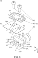
- the fixed member 40 of the present embodiment has a flat-plate shape. As shown in Figs. 8 and 9 , the fixed member 40 has an upper surface 40U and a lower surface 40L. As shown in Fig. 7 , the fixed member 40 is located below the substrate 16 in the up-down direction under the connected state where the connector assembly 12 is connected to the substrate 16. Referring to Figs. 7 and 9 , the fixed member 40 is in contact with the ground layer 78A of the substrate 16 under the connected state where the connector assembly 12 is connected to the substrate 16. As shown in Fig. 6 , the fixed member 40 is in contact with the outer terminal 24 under the connected state.
- the fixed member 40 is made of metal. It is noted that the fixed member 40 is preferred to have a surface treatment such as, for example, gold plating in order to make reliable contact with the substrate 16 and the outer terminal 24.
- the fixed member 40 has a main portion 401, a first contact portion 402, two spring portions 404 and two second contact portions 405.
- the present invention is not limited thereto.
- the number of the spring portion 404 may be one.
- the fixed member 40 should have the main portion 401, the first contact portion 402, at least one spring portion 404 and the two second contact portions 405.
- the main portion 401 of the present embodiment extends in the predetermined plane.
- the main portion 401 wholly extends in the predetermined plane.
- the present invention is not limited thereto. Specifically, a part of the main portion 401 should extend in the predetermined plane. In other words, the main portion 401 should mainly extend in the predetermined plane.
- the main portion 401 has two extending portions 4012. The extending portions 4012 are located at opposite ends, respectively, of the main portion 401 in the lateral direction.
- the first contact portion 402 of the present embodiment is provided on the main portion 401.
- the first contact portion 402 faces rearward in the front-rear direction.
- the first contact portion 402 defines a rear end of the main portion 401.
- the first contact portion 402 is a rear end surface of the main portion 401.
- the first contact portion 402 is located, at least in part, between the two second contact portions 405.
- the first contact portion 402 is in contact with the first receiving portion 252 under the connected state. In other words, the first contact portion 402 and the first receiving portion 252 are electrically connected with each other under the connected state.
- each of the spring portions 404 of the present embodiment extends from the main portion 401 and is resiliently deformable.
- the two spring portions 404 correspond to the two guide portions 256, respectively, of the flange portion 25 of the coaxial connector 20.
- Each of the spring portions 404 has a first portion 4041 and a second portion 4042.
- the first portion 4041 of the present embodiment extends in the front-rear direction. Specifically, the first portion 4041 extends mainly in the front-rear direction. When the fixed member 40 is viewed alone, the first portion 4041 extends rearward in the front-rear direction and inward in the lateral direction from the main portion 401. Specifically, when the fixed member 40 is viewed alone, the first portion 4041 extends rearward in the front-rear direction and inward in the lateral direction from the extending portion 4012 of the main portion 401.
- the second portion 4042 of the present embodiment extends in a direction intersecting with the front-rear direction from the first portion 4041. Specifically, the second portion 4042 extends inward in the lateral direction, which is perpendicular to the front-rear direction, from the first portion 4041.
- the two second contact portions 405 of the present embodiment are apart from each other in the lateral direction.
- the two spring portions 404 support the two second contact portions 405, respectively. Accordingly, each of the two second contact portions 405 is movable in the predetermined plane.
- the fixed member 40 should be configured so that at least one of the two second contact portions 405 is supported by the spring portion 404 while the at least one second contact portion 405 is movable in the predetermined plane.
- the second contact portion 405 is supported by the second portion 4042.
- the second contact portion 405 is located in the vicinity of an inner end of the second portion 4042 in the lateral direction. Referring to Fig.
- the guide portion 256 guides the second contact portion 405 to the second receiving portion 254 when the fixed member 40 is attached to the coaxial connector 20.
- the second contact portion 405 Under the connected state, the second contact portion 405 is in contact with the second receiving portion 254. Under the connected state, the second contact portion 405 of the fixed member 40 made of metal is electrically connected to the second receiving portion 254 of the flange portion 25 made of metal.
- the present invention is not limited thereto. Specifically, the second contact portion 405 and the second receiving portion 254 may not be electrically connected to each other under the connected state.
- the fixed member 40 has a first distance D1 between the second contact portion 405 and the first contact portion 402 in the front-rear direction when the fixed member 40 is viewed alone.
- the fixed member 40 has the first distance D1 between the second contact portion 405 and the first contact portion 402 in the front-rear direction under an initial state where the spring portion 404 is not resiliently deformed. If the fixed member 40 has only the single spring portion 404, the fixed member 40 should have the first distance D1 between the second contact portion 405, which is supported by the spring portion 404, and the first contact portion 402 in the front-rear direction when the fixed member 40 is viewed alone.
- the fixed member 40 should have the first distance D1 between the at least one second contact portion 405 and the first contact portion 402 in the front-rear direction when the fixed member 40 is viewed alone.
- the first distance D1 is smaller than the second distance D2. Accordingly, under the connected state, the flange portion 25 is sandwiched between the first contact portion 402 and the second contact portion 405 of the fixed member 40 via the first receiving portion 252 and the second receiving portion 254 while the spring portion 404 is resiliently deformed.
- the two spring portions 404 press the two second contact portions 405 against the two second receiving portions 254, respectively, under the connected state. More specifically, under the connected state, the spring portion 404 presses the second contact portion 405 against the second receiving portion 254 while the second contact portion 405 receives reaction force from the second receiving portion 254 by the pressing of the spring portion 404. Under the connected state, the first contact portion 402 is pressed against the first receiving portion 252 along the front-rear direction by the reaction force. Accordingly, the connector assembly 12 of the present embodiment is configured so that the fixed member 40 is securely connected to the outer terminal 24 of the coaxial connector 20.
- the ground layer 78A of the substrate 16 is electrically connected to the first receiving portion 252 of the flange portion 25 of the outer terminal 24 via the fixed member 40 in a highly reliable manner when the connector assembly 12 of the present embodiment is connected to the substrate 16. That is, in the connector assembly 12 of the present embodiment, the outer terminal 24 can be stably connected to the ground layer 78A of the substrate 16 and this can securely reduce reflection characteristics of signals propagating between the substrate 16 and the connector assembly 12.
- the fixed member 40 of the present embodiment is formed with two fixing holes 45.
- Each of the fixing holes 45 passes through the fixed member 40 in the up-down direction.
- each of the fixing holes 45 has a circular shape in the horizontal plane.
- the fixing holes 45 are provided at positions which correspond to those of the passing holes 72, respectively, of the substrate 16 in the horizontal plane.
- the thus-arranged two fixing holes 45 are apart from each other in the lateral direction and are located at positions same as each other in the front-rear direction.
- the fixed member 40 is arranged relative to the coaxial connector 20 and the substrate 16 in the up-down direction so that the lower surface 70L of the substrate 16 faces the upper surface 40U of the fixed member 40 in the up-down direction while each of the guide portions 256 of the coaxial connector 20 and the second contact portion 405 of the corresponding spring portion 404 of the fixed member 40 are located at positions same as each other in the horizontal plane.
- a structure 10A according to a first modification comprises a connector assembly 12A and a substrate 16.
- the substrate 16 of the present modification has a configuration same as that of the substrate 16 of the aforementioned embodiment. Accordingly, a detailed description thereabout is omitted.
- the connector assembly 12A is configured to be connected to the substrate 16 similarly to the connector assembly 12.
- the connector assembly 12B of the present modification comprises a coaxial connector 20, a fixed member 40B and two fixing members 60.
- the coaxial connector 20 and the fixing member 60 of the present modification have configurations same as those of the coaxial connector 20 and the fixing member 60 of the aforementioned embodiment. Accordingly, a detailed description thereabout is omitted.
- a structure 10E according to a fifth modification comprises a connector assembly 12E and a substrate 16.
- the substrate 16 of the present modification has a configuration same as that of the substrate 16 of the aforementioned embodiment. Accordingly, a detailed description thereabout is omitted.
- the connector assembly 12E is configured to be connected to the substrate 16 similarly to the connector assembly 12.
- the spring portion 404E of the present modification extends from the main portion 401E and is resiliently deformable.
- the spring portion 404E extends rearward in the front-rear direction from the main portion 401E.
- the spring portion 404E has a first portion 4041E and a second portion 4042E.
- the first portion 4041E of the present modification extends in the front-rear direction. Specifically, the first portion 4041E extends mainly in the front-rear direction. The first portion 4041E extends rearward in the front-rear direction and inward in the lateral direction from the main portion 401E when the fixed member 40E is viewed alone. Specifically, the first portion 4041E extends rearward in the front-rear direction and inward in the lateral direction from the extending portion 4012E of the main portion 401E when the fixed member 40E is viewed alone.
- the two second contact portions 405E of the present modification are apart from each other in the lateral direction.
- the second contact portions 405E are in contact with the second receiving portions 254E, respectively, under the connected state.
- the second contact portion 405E of the fixed member 40E made of metal is electrically connected to the second receiving portion 254E of the flange portion 25E made of metal.
- the present invention is not limited thereto. Specifically, the second contact portion 405E and the second receiving portion 254E may not be electrically connected to each other under connected state.
- the two second contact portions 405E include a second main contact portion 4051 and a second auxiliary contact portion 4052.
- the second main contact portion 4051 is located in the vicinity of an inner end of the second portion 4042E in the lateral direction.
- the second main contact portion 4051 is located rightward of the second auxiliary contact portion 4052 in the right-left direction.
- the spring portion 404E supports the second main contact portion 4051. Accordingly, the second main contact portion 4051 is movable in the predetermined plane.
- the guide portion 256E guides the second main contact portion 4051 to the second main receiving portion 2541 when the fixed member 40E is attached to the coaxial connector 20E. Under the connected state, the second main contact portion 4051 is in contact with the second main receiving portion 2541.
- the second auxiliary contact portion 4052 is located in the vicinity of an inner end of the supporting portion 406 in the lateral direction.
- the supporting portion 406 supports the second auxiliary contact portion 4052.
- the second auxiliary contact portion 4052 is located leftward of the second main contact portion 4051 in the right-left direction.
- the second auxiliary contact portion 4052 is located around a left end of the fixed member 40E in the right-left direction.
- the second auxiliary contact portion 4052 is in contact with the second auxiliary receiving portion 2542 under the connected state.
- the fixed member 40E has a distance between the second auxiliary contact portion 4052 and the first contact portion 402E in the front-rear direction when the fixed member 40E is viewed alone, and the distance is approximately equal to the second distance D2.
- the fixed member 40E has a first distance D1 between the second main contact portion 4051 and the first contact portion 402E in the front-rear direction when the fixed member 40E is viewed alone.
- the fixed member 40E has the first distance D1 between the second contact portion 405E and the first contact portion 402E in the front-rear direction when the fixed member 40E is viewed alone.
- the fixed member 40E has the first distance D1 between the second main contact portion 4051 and the first contact portion 402E in the front-rear direction under an initial state where the spring portion 404E is not resiliently deformed. Referring to Figs. 32 and 33 , the first distance D1 is smaller than the second distance D2.
- the flange portion 25E is sandwiched between the first contact portion 402E and the second main contact portion 4051 of the fixed member 40E via the first receiving portion 252 and the second main receiving portion 2541 while the spring portion 404E is resiliently deformed.
- the spring portion 404E presses the second main contact portion 4051 against the second main receiving portion 2541 while the second main contact portion 4051 receives reaction force from the second main receiving portion 2541 by the pressing of the spring portion 404E.
- the first contact portion 402E is pressed against the first receiving portion 252 along the front-rear direction by the reaction force. Accordingly, the connector assembly 12E of the present modification is configured so that the fixed member 40E is securely connected to the outer terminal 24E of the coaxial connector 20E.
- the ground layer 78A of the substrate 16 is electrically connected to the first receiving portion 252 of the flange portion 25E of the outer terminal 24E via the fixed member 40E in a highly reliable manner when the connector assembly 12E of the present modification is connected to the substrate 16. That is, in the connector assembly 12E of the present modification, the outer terminal 24E of the coaxial connector 20E of the connector assembly 12E can be stably connected to the ground layer 78A of the substrate 16 and this can securely reduce reflection characteristics of signals propagating between the substrate 16 and the connector assembly 12E.
- the first contact portion 402E which is located in the vicinity of the contact portion 214 of the center terminal 21 of the coaxial connector 20E, is pressed against the first receiving portion 252 along the front-rear direction under the connected state.
- This enables the fixed member 40E to be always in contact with the flange portion 25E at the vicinity of the contact portion 214 of the center terminal 21 of the coaxial connector 20E under the connected state.
- the connector assembly 12E of the present modification can securely reduce reflection characteristics of signals, which propagate between the substrate 16 and the connector assembly 12E, under connected state even if, for example, contact force between the first contact portion 402E and the first receiving portion 252 is not large.
- the fixed member 40E has a pressed portion 42E.
- the pressed portion 42E is a part which is configured to be pressed against the substrate 16 under the connected state (see Fig. 29 ).
- a middle part of the upper surface 40U in the lateral direction mainly works as the pressed portion 42E.
- the connector assembly 12E of the present modification is configured so that the second auxiliary receiving portion 2542 is located at the left end of the flange portion 25E while the second auxiliary contact portion 4052 supported by the supporting portion 406 is located around the left end of the fixed member 40E.
- the fixed member 40E receives force which urges the fixed member 40E to be rotated clockwise when the fixed member 40E is viewed from below.
- the second auxiliary receiving portion 2542 and the second auxiliary contact portion 4052 are arranged as described above.
- the second auxiliary receiving portion 2542 receives the force when the one of the fixing members 60 is screwed into the screw hole 28. This can prevent the rotation of the fixed member 400E relative to the flange portion 25E.
Landscapes
- Coupling Device And Connection With Printed Circuit (AREA)
Abstract
Description
- This invention relates to a connector assembly which is configured to be connected to a substrate.
- For example,
JPB 6853655 - Referring to
Figs. 34 and35 , a substrate-connector connection structure 900 of Patent Document 1 has asubstrate 950 and aconnector 910, or aconnector assembly 910. Specifically, theconnector assembly 910 is connected to thesubstrate 950. Thesubstrate 950 has asignal pattern 952, or asignal line 952, afirst ground layer 954 and aplating layer 956. Specifically, theplating layer 956 is located just below thesignal line 952 and is formed at a region including an end surface of thefirst ground layer 954. Theconnector assembly 910 comprises acoaxial connector 920 and twoscrews 930, or fixingmembers 930. Thecoaxial connector 920 has acenter conductor 922, or acenter terminal 922, and anouter conductor 924, or anouter terminal 924. When theconnector assembly 910 is connected to thesubstrate 950, theouter terminal 924 is brought into contact with theplating layer 956 which is electrically connected to thefirst ground layer 954. By this structure, the substrate-connector connection structure 900 of Patent Document 1 is configured to reduce reflection characteristics of signal propagating between thesubstrate 950 and theconnector assembly 910. - In the substrate-
connector connection structure 900 of Patent Document 1, it is difficult for theouter terminal 924 of thecoaxial connector 920 to be stably connected to theplating layer 956 of thesubstrate 950 when theconnector assembly 910 is connected to thesubstrate 950. Accordingly, the substrate-connector connection structure 900 of Patent Document 1 might not make a reliable electrical connection between theouter terminal 924 and thefirst ground layer 954. - It is therefore an object of the present invention to provide a connector assembly which enables an outer terminal of a coaxial connector of the connector assembly to be stably connected to a ground layer of a substrate.
- One aspect of the present invention provides a connector assembly configured to be connected to a substrate. The substrate is formed with two passing holes. Each of the passing holes passes through the substrate in an up-down direction. The substrate has an upper surface and a lower surface in the up-down direction. The upper surface of the substrate is formed with a signal line. The signal line is located between the two passing holes in a lateral direction perpendicular to the up-down direction. The lower surface of the substrate is formed with a ground layer. The connector assembly comprises a coaxial connector, a fixed member and two fixing members. The coaxial connector is configured to be attached to a distal end of a coaxial cable. The coaxial connector comprises an outer terminal and a center terminal. The outer terminal has a flange portion and two projecting portions. The flange portion has a first receiving portion and two second receiving portions. The first receiving portion faces forward in a front-rear direction perpendicular to both the up-down direction and the lateral direction. Each of the two second receiving portions faces at least rearward in the front-rear direction. The two projecting portions are apart from each other in the lateral direction. Each of the two projecting portions extends forward in the front-rear direction from the flange portion. The fixed member is made of metal. The fixed member is located below the substrate in the up-down direction under a connected state where the connector assembly is connected to the substrate. The ground layer of the substrate is electrically connected to the first receiving portion of the flange portion via the fixed member under the connected state. The fixed member has a main portion, a first contact portion, at least one spring portion and two second contact portions. The main portion extends in a predetermined plane. The first contact portion is provided at the main portion. The first contact portion is located, at least in part, between the two second contact portions. The spring portion extends from the main portion and is resiliently deformable. The two second contact portions are apart from each other in the lateral direction. At least one of the two second contact portions is supported by the spring portion and is movable in the predetermined plane. Under the connected state, the spring portion presses the second contact portion against the second receiving portion while the second contact portion receives reaction force from the second receiving portion by the pressing of the spring portion. The first contact portion is pressed against the first receiving portion along the front-rear direction by the reaction force under the connected state. Under the connected state, the two fixing members are fixed to the two projecting portions of the outer terminal through the two passing holes, respectively, of the substrate while the two fixing members press the fixed member against the ground layer of the substrate so that the predetermined plane becomes perpendicular to the up-down direction.
- The connector assembly of the present invention is configured as follows: under the connected state where the connector assembly is connected to the substrate, the spring portion presses the second contact portion against the second receiving portion while the second contact portion receives the reaction force from the second receiving portion by the pressing of the spring portion; and the first contact portion is pressed against the first receiving portion along the front-rear direction by the reaction force under the connected state. Accordingly, the connector assembly of the present invention is configured so that the fixed member is securely connected to the outer terminal of the coaxial connector. Thus, the ground layer of the substrate is electrically connected to the first receiving portion of the flange portion of the outer terminal via the fixed member in a highly reliable manner when the connector assembly of the present invention is connected to the substrate. In other words, the connector assembly of the present invention enables the outer terminal of the coaxial connector of the connector assembly to be stably connected to the ground layer of the substrate.
- An appreciation of the objectives of the present invention and a more complete understanding of its structure may be had by studying the following description of the preferred embodiment and by referring to the accompanying drawings.
-
-
Fig. 1 is a perspective view showing a structure according to an embodiment of the present invention. In the figure, a connector assembly is under a connected state where the connector assembly is connected to a substrate. -
Fig. 2 is another perspective view showing the structure ofFig. 1 . -
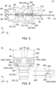
Fig. 3 is a top view showing the structure ofFig. 1 . -
Fig. 4 is a front view showing the structure ofFig. 1 . -
Fig. 5 is a cross-sectional view showing the structure ofFig. 4 , taken along line A-A. -
Fig. 6 is a bottom view showing the structure ofFig. 1 . In the figure, a part of the connector assembly is enlarged and illustrated. -
Fig. 7 is a side view showing the structure ofFig. 1 . -
Fig. 8 is an exploded, perspective view showing the structure ofFig. 1 . In the figure, a coaxial connector is under a pre-connected state where the coaxial connector is not yet connected to the substrate. -
Fig. 9 is another exploded, perspective view showing the structure ofFig. 2 . In the figure, the coaxial connector is under the pre-connected state where the coaxial connector is not yet connected to the substrate. -
Fig. 10 is a side view showing the coaxial connector which is included in the structure ofFig. 8 . -
Fig. 11 is a top view showing a fixed member which is included in the structure ofFig. 8 . -
Fig. 12 is a bottom view showing a first modification of the structure ofFig. 6 . -
Fig. 13 is a perspective view showing a fixed member which is included in the structure ofFig. 12 . In the figure, a spring portion is under an initial state where the spring portion is not resiliently deformed. -
Fig. 14 is a top view showing the fixed member ofFig. 13 . -
Fig. 15 is a bottom view showing a second modification of the structure ofFig. 6 . -
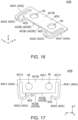
Fig. 16 is a perspective view showing a fixed member which is included in the structure ofFig. 15 . In the figure, a spring portion is under an initial state where the spring portion is not resiliently deformed. -
Fig. 17 is a top view showing the fixed member ofFig. 16 . -
Fig. 18 is a perspective view showing a third modification of the structure ofFig. 1 . In the figure, a connector assembly is under a connected state where the connector assembly is connected to a substrate. -
Fig. 19 is another perspective view showing the structure ofFig. 18 . -
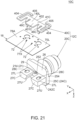
Fig. 20 is an exploded, perspective view showing the structure ofFig. 18 . In the figure, a coaxial connector is under a pre-connected state where the coaxial connector is not yet connected to the substrate. -
Fig. 21 is another exploded, perspective view showing the structure ofFig. 19 . -
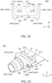
Fig. 22 is a top view showing a fixed member which is included in the structure ofFig. 20 . -
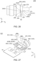
Fig. 23 is a perspective view showing a fourth modification of the structure ofFig. 1 . In the figure, a connector assembly is under a connected state where the connector assembly is connected to a substrate. -
Fig. 24 is another perspective view showing the structure ofFig. 23 . -
Fig. 25 is an exploded, perspective view showing the structure ofFig. 24 . In the figure, a coaxial connector is under a pre-connected state where the coaxial connector is not yet connected to the substrate. -
Fig. 26 is a side view showing the coaxial connector which is included in the structure ofFig. 23 . -
Fig. 27 is another perspective view showing the structure ofFig. 24 . In the figure, the substrate and fixing members are not attached to the coaxial connector, and the coaxial connector and a fixed member are under a temporary assembly state where the coaxial connector and the fixed member are temporally assembled. -
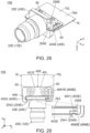
Fig. 28 is a perspective view showing a fifth modification of the structure ofFig. 1 . In the figure, a connector assembly is under a connected state where the connector assembly is connected to a substrate. -
Fig. 29 is a bottom view showing the structure ofFig. 28 . In the figure, a part of the connector assembly is enlarged and illustrated. -
Fig. 30 is an exploded, perspective view showing the structure ofFig. 28 . In the figure, a coaxial connector is under a pre-connected state where the coaxial connector is not yet connected to the substrate. -
Fig. 31 is a side view showing the coaxial connector which is included in the structure ofFig. 28 . -
Fig. 32 is another side view showing the coaxial connector ofFig. 31 . -
Fig. 33 is a top view showing a fixed member which is included in the structure ofFig. 30 . -
Fig. 34 is a perspective view showing a substrate-connector connection structure of Patent Document 1. -
Fig. 35 is a cross-sectional view showing a part of the substrate-connector connection structure ofFig. 34 . - While the invention is susceptible to various modifications and alternative forms, specific embodiments thereof are shown by way of example in the drawings and will herein be described in detail. It should be understood, however, that the drawings and detailed description thereto are not intended to limit the invention to the particular form disclosed, but on the contrary, the intention is to cover all modifications, equivalents and alternatives falling within the spirit and scope of the present invention as defined by the appended claims.
- Referring to
Fig. 2 , astructure 10 according to an embodiment of the present invention comprises aconnector assembly 12 and asubstrate 16. Thesubstrate 16 extends along a horizontal plane. Theconnector assembly 12 is configured to be connected to thesubstrate 16. In detail, theconnector assembly 12 is configured to be connected to a rear end portion of thesubstrate 16 in a front-rear direction parallel to the horizontal plane. Theconnector assembly 12 of each ofFigs. 1 to 7 is under a connected state where theconnector assembly 12 is connected to thesubstrate 16. In contrast, theconnector assembly 12 of each ofFigs. 8 and9 is under a pre-connected state where theconnector assembly 12 is not yet connected to thesubstrate 16. - The horizontal plane of the present embodiment is an XY-plane. The front-rear direction of the present embodiment is an X-direction. In the present embodiment, "forward" means a positive X-direction, and "rearward" means a negative X-direction. The words such as the horizontal plane and the front-rear direction do not indicate the absolute positional relation relative to the ground but merely indicate a relative positional relation under a definition where the
substrate 16 extends in the horizontal plane and where theconnector assembly 12 is located rearward of thissubstrate 16. - Referring to
Figs. 8 and9 , thesubstrate 16 is not specifically limited. Specifically, thesubstrate 16 may be a flexible board, or may be a rigid substrate. - As shown in
Figs. 8 and9 , thesubstrate 16 has anupper surface 70U and alower surface 70L in an up-down direction perpendicular to the horizontal plane. Theupper surface 70U and thelower surface 70L are located at an upper end and a lower end of a base 70, respectively. The up-down direction of the present embodiment is a Z-direction. In the present embodiment, "upward" means a positive Z-direction, and "downward" means a negative Z-direction. - As shown in
Fig. 8 , thesubstrate 16 is formed with two passingholes 72. Each of the passing holes 72 passes through thesubstrate 16 in the up-down direction. Each of the passing holes 72 has a circular shape in the horizontal plane. The thus-formed passing holes 72 are used when theconnector assembly 12 is screwed to thesubstrate 16 as described later. The two passingholes 72 are apart from each other in a lateral direction perpendicular to both the front-rear direction and the up-down direction and are located at positions same as each other in the front-rear direction. The lateral direction of the present embodiment is a Y-direction. In addition, the lateral direction is also referred to as a right-left direction. In the present embodiment, "rightward" means a positive Y-direction, and "leftward" means a negative Y-direction. - The passing holes 72 of the present embodiment are formed as described above. However, the present invention is not limited thereto. For example, the shape of each of the passing holes 72 is not specifically limited. Moreover, the number of the passing holes 72 may be three or more. In this instance, two of the passing holes 72 may be apart from each other in the lateral direction and may be located at positions same as each other in the front-rear direction.
- As shown in
Fig. 8 , theupper surface 70U of thesubstrate 16 is formed with asignal line 74 which is a conductive pattern. Thesignal line 74 extends in the front-rear direction and is located between the two passingholes 72 in the lateral direction. - As shown in
Fig. 9 , thelower surface 70L of thesubstrate 16 is formed with aground layer 78A which is a conductive pattern and covers the whole of thelower surface 70L. - Referring to
Fig. 3 , thesignal line 74 of an instance is connected to an antenna which is formed on an unillustrated front end part of thesubstrate 16. In this instance, theconnector assembly 12 under the connected state transmits signals to the antenna through thesignal line 74. The thus-transmitted signals are sent outward from the antenna. On the other hand, signals received by the antenna are transmitted to theconnector assembly 12 through thesignal line 74. Thestructure 10 of the present embodiment is uses as described above, for example. In other words, thestructure 10 of the present embodiment is an antenna device. However, the usage of thestructure 10 of the present invention is not specifically limited. Thestructure 10 of the present invention may be any electric device with thesubstrate 16. - As shown in
Fig. 8 , thesubstrate 16 comprises twolands 76X each of which is a conductive pattern. The two passingholes 72 pass through thelands 76X, respectively. Each of thelands 76X is formed with a plurality of viaholes 77X. Each of the via holes 77X passes through the base 70 and theland 76X in the up-down direction, and thereby each of thelands 76X is electrically connected with theground layer 78A (seeFig. 9 ) of thelower surface 70L. - The
substrate 16 of the present embodiment has the aforementioned configuration. However, the configuration of thesubstrate 16 can be modified in accordance with the usage of thestructure 10. For example, theground layer 78A may be partially formed on thelower surface 70L. - Referring to
Fig. 9 , theconnector assembly 12 of the present embodiment comprises acoaxial connector 20, a fixedmember 40 and two fixingmembers 60, or twoscrews 60. Theconnector assembly 12 of the present embodiment comprises only the aforementioned members. However, the present invention is not limited thereto. For example, theconnector assembly 12 may further comprise another member in addition to the aforementioned members. - Hereafter, explanation will be made about the
coaxial connector 20, the fixedmember 40 and the fixingmembers 60 of the present embodiment in this order. - Referring to
Fig. 5 , thecoaxial connector 20 of the present embodiment is configured to be attached to a distal end of acoaxial cable 80. Specifically, thecoaxial connector 20 is configured to be attached to a front end of thecoaxial cable 80. Thecoaxial connector 20 of the present embodiment is a so-called sub miniature type A (SMA) connector. However, the present invention is not limited thereto but applicable to variouscoaxial connectors 20. - Referring to
Fig. 5 , thecoaxial cable 80 illustrated with dashed line is a typical coaxial cable and comprises acenter conductor 82 made of conductor, aninner insulator 84 made of insulator and covering thecenter conductor 82, anouter conductor 86 made of conductor and covering theinner insulator 84 and asheath 88 made of insulator and covering theouter conductor 86. The number of thecenter conductor 82 of the present embodiment is one. The configuration of thecoaxial connector 20 is not specifically limited, provided that the number of thecenter conductor 82 is one. For example, theouter conductor 86 may be a braid formed of fine metal wires or may be made of metal foil. For example, thecoaxial cable 80 may be connected to a rear end of thecoaxial connector 20 via amating connector 89 attached to thecoaxial cable 80. - Referring to
Fig. 5 , thecoaxial connector 20 of the present embodiment comprises acenter terminal 21 made of metal and anouter terminal 24 made of metal. - As shown in
Fig. 5 , thecenter terminal 21 of the present embodiment extends along the front-rear direction and has abody 212, acontact portion 214 and aconnection portion 218. Thebody 212 is a middle part of thecenter terminal 21 in the front-rear direction. Thecontact portion 214 extends forward from thebody 212. As shown inFig. 10 , thecontact portion 214 is bent downward in the up-down direction after thecoaxial connector 20 is assembled. Specifically, thecontact portion 214 extends forward and downward under a pre-connected state where theconnector assembly 12 is not yet connected to thesubstrate 16. Thecontact portion 214 defines a front end of thecenter terminal 21 in the front-rear direction. As shown inFig. 5 , theconnection portion 218 has a socket shape and extends rearward from thebody 212. Theconnection portion 218 defines a rear end of thecenter terminal 21 in the front-rear direction. Thecenter terminal 21 is connected with thecenter conductor 82 of thecoaxial cable 80 when thecoaxial connector 20 is attached to thecoaxial cable 80. In detail, theconnection portion 218 of thecenter terminal 21 is configured to be electrically connected with thecenter conductor 82. Thecenter terminal 21 and thecenter conductor 82 connected to each other transmit signals to each other. - The
center terminal 21 of the present embodiment has the aforementioned configuration. However, the configuration of thecenter terminal 21 can be modified as necessary, provided that thecenter terminal 21 has thecontact portion 214 which extends along the front-rear direction. - As shown in
Fig. 5 , theouter terminal 24 of the present embodiment comprises a frontconductive member 242 and a rearconductive member 244. The frontconductive member 242 is combined with the rearconductive member 244 and is located forward of the rearconductive member 244. The frontconductive member 242 is in contact with the rearconductive member 244. Theouter terminal 24 of the present embodiment consists of the aforementioned two members. However, the present invention is not limited thereto. For example, the frontconductive member 242 and the rearconductive member 244 may be a member integrally formed with each other. - Referring to
Fig. 5 , theouter terminal 24 is electrically connected with theouter conductor 86 of thecoaxial cable 80 when thecoaxial connector 20 is attached to thecoaxial cable 80. In detail, the rearconductive member 244 of theouter terminal 24 is configured to be electrically connected with theouter conductor 86. Theouter terminal 24 and theouter conductor 86 connected to each other have ground potentials same as each other. - As shown in
Fig. 9 , theouter terminal 24 has aflange portion 25 and two projectingportions 27. - As shown in
Figs. 8 and9 , theflange portion 25 of the present embodiment has afirst receiving portion 252 and twosecond receiving portions 254. - As shown in
Fig. 9 , the first receivingportion 252 faces forward in the front-rear direction perpendicular to both the up-down direction and the lateral direction. Thefirst receiving portion 252 is located around a middle of theflange portion 25 in the up-down direction. Thefirst receiving portion 252 is located at a middle of theflange portion 25 in the lateral direction. Referring toFigs. 2 and9 , under the connected state, theground layer 78A of thesubstrate 16 is electrically connected to the first receivingportion 252 of theflange portion 25 via the fixedmember 40. - As shown in
Fig. 6 , each of the twosecond receiving portions 254 faces rearward in the front-rear direction. However, the present invention is not limited thereto. Thesecond receiving portion 254 may face rearward in the front-rear direction and outward in the lateral direction. In other words, each of the twosecond receiving portions 254 should face at least rearward in the front-rear direction. Thesecond receiving portions 254 are located at opposite ends, respectively, of theflange portion 25 in the lateral direction. - As shown in
Fig. 10 , the first receivingportion 252 is located forward of any of thesecond receiving portions 254 in the front-rear direction. However, the present invention is not limited thereto. Thefirst receiving portion 252 may be located rearward of thesecond receiving portion 254 in the front-rear direction, provided that the first receivingportion 252 faces forward while thesecond receiving portion 254 faces at least rearward. If the first receivingportion 252 and thesecond receiving portions 254 are configured similar to the present embodiment, theflange portion 25 can have a reduced size in the front-rear direction. Accordingly, the first receivingportion 252 and thesecond receiving portions 254 of the present embodiment are more preferable. Theflange portion 25 has a second distance D2 between the first receivingportion 252 and any of thesecond receiving portions 254 in the front-rear direction. - Referring to
Fig. 8 , theflange portion 25 of the present embodiment has twoguide portions 256. Each of theguide portion 256 is oblique to both the front-rear direction and the up-down direction. Theguide portion 256 is located below thesecond receiving portion 254 in the up-down direction. Theguide portions 256 correspond to thesecond receiving portions 254, respectively. Each of theguide portions 256 is located below the corresponding second receivingportion 254 in the up-down direction. - As shown in
Fig. 9 , the two projectingportions 27 of the present embodiment are apart from each other in the lateral direction. Thecontact portion 214 is located between the two projectingportions 27 in the lateral direction. Each of the two projectingportions 27 extends forward in the front-rear direction from theflange portion 25. The two projectingportions 27 of the present embodiment have a mirror symmetric shape with respect to a predetermined plane, or to an XZ-plane. The thus-arranged two projectingportions 27 are located at positions same as each other in the up-down direction. Each of the two projectingportions 27 has anupper surface 27U and alower surface 27L in the up-down direction. Each of theupper surface 27U and thelower surface 27L is a flat surface in parallel to the horizontal plane. Theupper surface 27U defines an upper end of the projectingportion 27 in the up-down direction. Thelower surface 27L defines an lower end of the projectingportion 27 in the up-down direction. As shown inFig. 10 , a lower end of thecontact portion 214 is located downward of thelower surface 27L of the projectingportion 27 under the pre-connected state. Referring toFigs. 7 ,8 and9 , theouter terminal 24 is grounded to theground layer 78A of thesubstrate 16 via the projectingportions 27 and thelands 76X under the connected state. - As shown in
Fig. 9 , each of the projectingportions 27 of the present embodiment is formed with ascrew hole 28. Each of the screw holes 28 of the present embodiment passes through the projectingportion 27 in the up-down direction. The screw holes 28 are provided at positions which correspond to those of the passing holes 72, respectively, of thesubstrate 16 in the horizontal plane. Specifically, the twoscrew holes 28 are apart from each other in the lateral direction and are located at positions same as each other in the front-rear direction. The number of the screw holes 28 of the present embodiment is two. However, the present invention is not limited thereto. For example, each of the projectingportions 27 may be formed with two or more of the screw holes 28. Each of the screw holes 28 may be a hole with a ceiling. - As shown in
Fig. 4 , theouter terminal 24 of the present embodiment is formed with acenter hole 29. Thecenter hole 29 has a circular shape in a YZ-plane. Thecenter hole 29 is located between the two projectingportions 27 in the lateral direction. Thecenter terminal 21 is located at the center of thecenter hole 29 in the YZ-plane. - As shown in
Fig. 9 , theouter terminal 24 further has anend surface 26. Theend surface 26 of the present embodiment is a plane parallel to the YZ-plane. Thefirst receiving portion 252 is a part of theend surface 26 of theflange portion 25. Each of the projectingportions 27 projects forward in the front-rear direction fromend surface 26. Thecontact portion 214 of thecenter terminal 21 is located forward of theend surface 26. Thecontact portion 214 extends forward in the front-rear direction beyond theend surface 26. - The
end surface 26, the projectingportions 27 and thecontact portion 214 of the present embodiment have the aforementioned configurations and are arranged as described above. However, the present invention is not limited thereto, but the configurations and the arrangement of theend surface 26, the projectingportions 27 and thecontact portion 214 can be modified as necessary. - As shown in
Fig. 5 , thecoaxial connector 20 of the present embodiment further comprises aninsulation member 22. Thecoaxial connector 20 of the present embodiment comprises only thecenter terminal 21, theinsulation member 22 and theouter terminal 24. However, the present invention is not limited thereto. For example, thecoaxial connector 20 may further comprise another member in addition to the aforementioned members. - As shown in
Fig. 5 , theinsulation member 22 encloses thebody 212 of thecenter terminal 21 in a vertical plane, or in the YZ-plane, perpendicular to the front-rear direction. Theouter terminal 24 encloses theinsulation member 22 in the YZ-plane. The thus-arrangedinsulation member 22 is located between thecenter terminal 21 and theouter terminal 24 in the YZ-plane. In other words, theinsulation member 22 insulates theouter terminal 24 and thecenter terminal 21 from each other. Thecenter terminal 21, theinsulation member 22 and theouter terminal 24 of the present embodiment are arrange as described above. However, the arrangement of thecenter terminal 21, theinsulation member 22 and theouter terminal 24 is not specifically limited, provided that theouter terminal 24 and thecenter terminal 21 are insulated from each other by theinsulation member 22. - As shown in
Fig. 9 , the fixedmember 40 of the present embodiment has a flat-plate shape. As shown inFigs. 8 and9 , the fixedmember 40 has anupper surface 40U and alower surface 40L. As shown inFig. 7 , the fixedmember 40 is located below thesubstrate 16 in the up-down direction under the connected state where theconnector assembly 12 is connected to thesubstrate 16. Referring toFigs. 7 and9 , the fixedmember 40 is in contact with theground layer 78A of thesubstrate 16 under the connected state where theconnector assembly 12 is connected to thesubstrate 16. As shown inFig. 6 , the fixedmember 40 is in contact with theouter terminal 24 under the connected state. The fixedmember 40 is made of metal. It is noted that the fixedmember 40 is preferred to have a surface treatment such as, for example, gold plating in order to make reliable contact with thesubstrate 16 and theouter terminal 24. - As shown in
Fig. 11 , the fixedmember 40 has amain portion 401, afirst contact portion 402, twospring portions 404 and twosecond contact portions 405. However, the present invention is not limited thereto. Specifically, the number of thespring portion 404 may be one. In other words, the fixedmember 40 should have themain portion 401, thefirst contact portion 402, at least onespring portion 404 and the twosecond contact portions 405. - As shown in
Fig. 9 , themain portion 401 of the present embodiment extends in the predetermined plane. In detail, themain portion 401 wholly extends in the predetermined plane. However, the present invention is not limited thereto. Specifically, a part of themain portion 401 should extend in the predetermined plane. In other words, themain portion 401 should mainly extend in the predetermined plane. As shown inFig. 11 , themain portion 401 has two extendingportions 4012. The extendingportions 4012 are located at opposite ends, respectively, of themain portion 401 in the lateral direction. - As shown in
Fig. 11 , thefirst contact portion 402 of the present embodiment is provided on themain portion 401. Thefirst contact portion 402 faces rearward in the front-rear direction. Thefirst contact portion 402 defines a rear end of themain portion 401. Thefirst contact portion 402 is a rear end surface of themain portion 401. Thefirst contact portion 402 is located, at least in part, between the twosecond contact portions 405. As shown inFig. 6 , thefirst contact portion 402 is in contact with the first receivingportion 252 under the connected state. In other words, thefirst contact portion 402 and the first receivingportion 252 are electrically connected with each other under the connected state. - As shown in
Fig. 11 , each of thespring portions 404 of the present embodiment extends from themain portion 401 and is resiliently deformable. Referring toFig. 6 , the twospring portions 404 correspond to the twoguide portions 256, respectively, of theflange portion 25 of thecoaxial connector 20. Each of thespring portions 404 has afirst portion 4041 and asecond portion 4042. - As shown in
Fig. 11 , thefirst portion 4041 of the present embodiment extends in the front-rear direction. Specifically, thefirst portion 4041 extends mainly in the front-rear direction. When the fixedmember 40 is viewed alone, thefirst portion 4041 extends rearward in the front-rear direction and inward in the lateral direction from themain portion 401. Specifically, when the fixedmember 40 is viewed alone, thefirst portion 4041 extends rearward in the front-rear direction and inward in the lateral direction from the extendingportion 4012 of themain portion 401. - As shown in
Fig. 11 , thesecond portion 4042 of the present embodiment extends in a direction intersecting with the front-rear direction from thefirst portion 4041. Specifically, thesecond portion 4042 extends inward in the lateral direction, which is perpendicular to the front-rear direction, from thefirst portion 4041. - As shown in
Fig. 11 , the twosecond contact portions 405 of the present embodiment are apart from each other in the lateral direction. The twospring portions 404 support the twosecond contact portions 405, respectively. Accordingly, each of the twosecond contact portions 405 is movable in the predetermined plane. However, the present invention is not limited thereto. The fixedmember 40 should be configured so that at least one of the twosecond contact portions 405 is supported by thespring portion 404 while the at least onesecond contact portion 405 is movable in the predetermined plane. Thesecond contact portion 405 is supported by thesecond portion 4042. Thesecond contact portion 405 is located in the vicinity of an inner end of thesecond portion 4042 in the lateral direction. Referring toFig. 6 , as described later, theguide portion 256 guides thesecond contact portion 405 to thesecond receiving portion 254 when the fixedmember 40 is attached to thecoaxial connector 20. Under the connected state, thesecond contact portion 405 is in contact with thesecond receiving portion 254. Under the connected state, thesecond contact portion 405 of the fixedmember 40 made of metal is electrically connected to thesecond receiving portion 254 of theflange portion 25 made of metal. However, the present invention is not limited thereto. Specifically, thesecond contact portion 405 and thesecond receiving portion 254 may not be electrically connected to each other under the connected state. - As shown in
Fig. 11 , the fixedmember 40 has a first distance D1 between thesecond contact portion 405 and thefirst contact portion 402 in the front-rear direction when the fixedmember 40 is viewed alone. In other words, the fixedmember 40 has the first distance D1 between thesecond contact portion 405 and thefirst contact portion 402 in the front-rear direction under an initial state where thespring portion 404 is not resiliently deformed. If the fixedmember 40 has only thesingle spring portion 404, the fixedmember 40 should have the first distance D1 between thesecond contact portion 405, which is supported by thespring portion 404, and thefirst contact portion 402 in the front-rear direction when the fixedmember 40 is viewed alone. That is, if at least one of the twosecond contact portions 405 is supported by thespring portion 404, the fixedmember 40 should have the first distance D1 between the at least onesecond contact portion 405 and thefirst contact portion 402 in the front-rear direction when the fixedmember 40 is viewed alone. Referring toFigs. 10 and 11 , the first distance D1 is smaller than the second distance D2. Accordingly, under the connected state, theflange portion 25 is sandwiched between thefirst contact portion 402 and thesecond contact portion 405 of the fixedmember 40 via the first receivingportion 252 and thesecond receiving portion 254 while thespring portion 404 is resiliently deformed. - Referring to
Fig. 6 , the twospring portions 404 press the twosecond contact portions 405 against the twosecond receiving portions 254, respectively, under the connected state. More specifically, under the connected state, thespring portion 404 presses thesecond contact portion 405 against thesecond receiving portion 254 while thesecond contact portion 405 receives reaction force from thesecond receiving portion 254 by the pressing of thespring portion 404. Under the connected state, thefirst contact portion 402 is pressed against the first receivingportion 252 along the front-rear direction by the reaction force. Accordingly, theconnector assembly 12 of the present embodiment is configured so that the fixedmember 40 is securely connected to theouter terminal 24 of thecoaxial connector 20. Thus, theground layer 78A of thesubstrate 16 is electrically connected to the first receivingportion 252 of theflange portion 25 of theouter terminal 24 via the fixedmember 40 in a highly reliable manner when theconnector assembly 12 of the present embodiment is connected to thesubstrate 16. That is, in theconnector assembly 12 of the present embodiment, theouter terminal 24 can be stably connected to theground layer 78A of thesubstrate 16 and this can securely reduce reflection characteristics of signals propagating between thesubstrate 16 and theconnector assembly 12. - As shown in
Fig. 8 , the fixedmember 40 has a pressedportion 42. As described later, the pressedportion 42 is a part which is configured to be pressed against thesubstrate 16 under the connected state. According to the present embodiment, a middle part of theupper surface 40U in the lateral direction mainly works as the pressedportion 42. - As shown in
Fig. 9 , the fixedmember 40 of the present embodiment is formed with two fixingholes 45. Each of the fixing holes 45 passes through the fixedmember 40 in the up-down direction. As shown inFig. 11 , each of the fixing holes 45 has a circular shape in the horizontal plane. Referring toFig. 8 , the fixing holes 45 are provided at positions which correspond to those of the passing holes 72, respectively, of thesubstrate 16 in the horizontal plane. The thus-arranged two fixingholes 45 are apart from each other in the lateral direction and are located at positions same as each other in the front-rear direction. - The fixed
member 40 of the present embodiment has the aforementioned configuration. However, the present invention is not limited thereto. For example, the shape of each of the fixing holes 45 is not specifically limited. Moreover, the number of the fixing holes 45 may be three or more. - Referring to
Fig. 7 , theconnector assembly 12 forms thestructure 10 together with thesubstrate 16 connected thereto. Thesubstrate 16 of thestructure 10 is located between the fixedmember 40 and each of the projectingportions 27 of theouter terminal 24 in the up-down direction. Referring toFigs. 3 and5 , thesignal line 74 of thesubstrate 16 is pressed by the fixedmember 40 from below, and thereby thesignal line 74 is pressed against and in contact with thecontact portion 214 of thecenter terminal 21. Accordingly, thecontact portion 214 and thesignal line 74 are electrically connected to each other. However, the present invention is not limited thereto. Specifically, thecontact portion 214 and thesignal line 74 may be connected to each other by soldering. - As shown in
Fig. 9 , the two fixingmembers 60 of the present embodiment have shapes same as each other. More specifically, each of the fixingmembers 60 of the present embodiment is ascrew 60. Accordingly, each of the fixingmembers 60 is formed with a thread (not shown). More in detail, each of the fixingmembers 60 is a right-hand screw 60 made of metal. The fixingmembers 60 are provided so that they correspond to the passing holes 72, respectively, of thesubstrate 16. Accordingly, the number of the fixingmembers 60 of the present embodiment is two. However, the present invention is not limited thereto. For example, theconnector assembly 12 may be provided with three or more of the fixingmembers 60 which have shapes different from each other. Referring toFigs. 2 and9 , each of the fixingmembers 60 is screwed into thescrew hole 28 through the fixinghole 45 of the fixedmember 40 and the passinghole 72 of thesubstrate 16 under the connected state. - The
connector assembly 12 of the present embodiment is configured to be connected to thesubstrate 16 by a connection method described below. The connection method described below is merely an example and can be modified as necessary. - Referring to
Figs. 8 and9 , thecoaxial connector 20 and thesubstrate 16 are firstly arranged in the up-down direction so that thelower surface 27L of the projectingportion 27 of thecoaxial connector 20 and theupper surface 70U of thesubstrate 16 are in contact with each other in the up-down direction while thescrew hole 28 of thecoaxial connector 20 and the passinghole 72 of thesubstrate 16 are located at positions same as each other in the horizontal plane. - Next, the fixed
member 40 is arranged relative to thecoaxial connector 20 and thesubstrate 16 in the up-down direction so that thelower surface 70L of thesubstrate 16 faces theupper surface 40U of the fixedmember 40 in the up-down direction while each of theguide portions 256 of thecoaxial connector 20 and thesecond contact portion 405 of thecorresponding spring portion 404 of the fixedmember 40 are located at positions same as each other in the horizontal plane. - After that, the fixed
member 40 is moved so that it approaches thecoaxial connector 20 and thesubstrate 16 in the up-down direction. Then, thesecond contact portion 405 of the fixedmember 40 is brought into contact with theguide portion 256 of thecoaxial connector 20. - From this state, the fixed
member 40 is further moved so that it approaches thecoaxial connector 20 and thesubstrate 16 in the up-down direction. Then, thesecond contact portion 405 of the fixedmember 40 rides over theguide portion 256 of thecoaxial connector 20 and rides on the corresponding second receivingportion 254 of thecoaxial connector 20, while theupper surface 40U of the fixedmember 40 is brought into contact with thelower surface 70L of thesubstrate 16 in the up-down direction. - In this state, the
first contact portion 402 of the fixedmember 40 is in contact with the first receivingportion 252 of thecoaxial connector 20 in the front-rear direction while thesecond contact portion 405 of the fixedmember 40 is in contact with the corresponding second receivingportion 254 of thecoaxial connector 20 in the front-rear direction. Additionally, in this state, each of thespring portions 404 presses the correspondingsecond contact portion 405 against the corresponding second receivingportion 254 while thesecond contact portion 405 receives the reaction force from thesecond receiving portion 254 by the pressing of thespring portion 404. Furthermore, in this state, thefirst contact portion 402 is pressed against the first receivingportion 252 along the front-rear direction by the reaction force. - After that, each of the fixing
members 60 is screwed into thescrew hole 28 of the projectingportion 27 of thecoaxial connector 20 through the fixinghole 45 of the fixedmember 40 and the passinghole 72 of thesubstrate 16. Accordingly, theconnector assembly 12 changes its state into the connected state where theconnector assembly 12 is connected to thesubstrate 16. - Referring to
Figs. 3 and5 , thecontact portion 214 of thecenter terminal 21 is brought into contact with thesignal line 74 of thesubstrate 16 under the connected state. As described above, under the pre-connected state, thecontact portion 214 of thecenter terminal 21 extends forward and downward while the lower end of thecontact portion 214 is located downward of thelower surface 27L of the projectingportion 27. Accordingly, under the connected state, thecontact portion 214 is brought into abutment with thesignal line 74 of thesubstrate 16 and is resiliently deformed. This resilient deformation generates restoring force which presses thecontact portion 214 against thesignal line 74 from above. - As shown in
Fig. 5 , the fixedmember 40 is located below thesubstrate 16 in the up-down direction under the connected state. Referring toFigs. 5 and9 , under the connected state, a head of each of the fixingmembers 60 is pressed against thelower surface 40L of the fixedmember 40 and presses the fixedmember 40 upward. Theupper surface 40U of the thus-pressedfixed member 40 presses thesubstrate 16 against thelower surfaces 27L of the projectingportions 27. As a result, thesubstrate 16 is sandwiched and held between the fixedmember 40 and each of the projectingportions 27. The thus-sandwichedsubstrate 16 has a contact region which is located below thecontact portion 214 of thecenter terminal 21. The pressed portion 42 (seeFig. 8 ) of the fixedmember 40 is pressed against the contact region of thesubstrate 16 and supports the contact region from below. If thesubstrate 16 is a flexible board, the contact region of thesubstrate 16 is not bent even when force is applied thereto from above. Under the connected state, the fixedmember 40 is pressed against theground layer 78A of thesubstrate 16 so that the predetermined plane becomes perpendicular to the up-down direction. - That is, under the connected state, the two fixing
members 60 are fixed to the two projectingportions 27 of theouter terminal 24 through the two passingholes 72, respectively, of thesubstrate 16 while the two fixingmembers 60 press the fixedmember 40 against theground layer 78A of thesubstrate 16 so that the predetermined plane becomes perpendicular to the up-down direction. - Referring to
Figs. 4 and9 , theouter terminal 24 is grounded to theground layer 78A of thelower surface 70L of thesubstrate 16 via the projectingportions 27, the fixingmembers 60 and the fixedmember 40 under the connected state. - The
structure 10 of the present embodiment can be further variously modified in addition to the already explained various modifications. Hereafter, explanation will be made about fifth modifications of thestructure 10, focusing on differences from thestructure 10. - Comparing
Fig. 12 withFig. 6 , astructure 10A according to a first modification comprises aconnector assembly 12A and asubstrate 16. Thesubstrate 16 of the present modification has a configuration same as that of thesubstrate 16 of the aforementioned embodiment. Accordingly, a detailed description thereabout is omitted. Theconnector assembly 12A is configured to be connected to thesubstrate 16 similarly to theconnector assembly 12. - As shown in
Fig. 12 , theconnector assembly 12A of the present modification comprises acoaxial connector 20, a fixedmember 40A and two fixingmembers 60. Thecoaxial connector 20 and the fixingmember 60 of the present modification have configurations same as those of thecoaxial connector 20 and the fixingmember 60 of the aforementioned embodiment. Accordingly, a detailed description thereabout is omitted. - As shown in
Fig. 14 , the fixedmember 40A of the present modification has amain portion 401A, afirst contact portion 402A, twospring portions 404 and twosecond contact portions 405. Thespring portion 404 and thesecond contact portion 405 of the present modification have configurations same as those of thespring portion 404 and thesecond contact portion 405 of the aforementioned embodiment. Accordingly, a detailed description thereabout is omitted. - As shown in
Fig. 14 , themain portion 401A of the present modification extends in the predetermined plane. In detail, themain portion 401A wholly extends in the predetermined plane. Themain portion 401A has two extendingportions 4012. The extendingportion 4012 of the preset modification has a configuration same as that of the extendingportion 4012 of the aforementioned embodiment. Accordingly, a detailed description thereabout is omitted. - As shown in
Fig. 14 , thefirst contact portion 402A of the present modification consists of aprotrusion 403. Theprotrusion 403 is located at a middle of the fixedmember 40A in the lateral direction. Theprotrusion 403 protrudes rearward in the front-rear direction from themain portion 401A. As shown inFig. 12 , theprotrusion 403 is in contact with afirst receiving portion 252 under a connected state where theconnector assembly 12A is connected to thesubstrate 16. In other words, theprotrusion 403 of the fixedmember 40A and the first receivingportion 252 of aflange portion 25 are electrically connected to each other under the connected state. Referring toFigs. 12 and3 , theprotrusion 403 is located between two projectingportions 27 in the lateral direction under the connected state. Theprotrusion 403 is located at a position same as that of acontact portion 214 of acenter terminal 21 in the lateral direction under the connected state. Theprotrusion 403 is located in the vicinity of thecontact portion 214 of thecenter terminal 21 under the connected state. - As shown in
Fig. 14 , the fixedmember 40A has a first distance D1 between thesecond contact portion 405 and thefirst contact portion 402A in the front-rear direction when the fixedmember 40A is viewed alone. In other words, the fixedmember 40A has the first distance D1 between thesecond contact portion 405 and thefirst contact portion 402A in the front-rear direction under an initial state where thespring portion 404 is not resiliently deformed. Referring toFigs. 10 and14 , the first distance D1 is smaller than a second distance D2. Accordingly, under the connected state, theflange portion 25 is sandwiched between thefirst contact portion 402A and thesecond contact portion 405 of the fixedmember 40A via the first receivingportion 252 and asecond receiving portion 254 while thespring portion 404 is resiliently deformed. - Referring to
Fig. 12 , the twospring portions 404 press the twosecond contact portions 405 against twosecond receiving portions 254, respectively, under the connected state. More specifically, under the connected state, thespring portion 404 presses thesecond contact portion 405 against thesecond receiving portion 254 while thesecond contact portion 405 receives reaction force from thesecond receiving portion 254 by the pressing of thespring portion 404. Under the connected state, thefirst contact portion 402A is pressed against the first receivingportion 252 along the front-rear direction by the reaction force. Accordingly, theconnector assembly 12A of the present modification is also configured so that the fixedmember 40A is securely connected to anouter terminal 24 of thecoaxial connector 20. Thus, aground layer 78A of thesubstrate 16 is electrically connected to the first receivingportion 252 of theflange portion 25 of theouter terminal 24 via the fixedmember 40A in a highly reliable manner when theconnector assembly 12A of the present modification is connected to thesubstrate 16. That is, in theconnector assembly 12A of the present modification, theouter terminal 24 of thecoaxial connector 20 of theconnector assembly 12A can be stably connected to theground layer 78A of thesubstrate 16 and this can securely reduce reflection characteristics of signals propagating between thesubstrate 16 and theconnector assembly 12A. - As described above, the
first contact portion 402A, which is located in the vicinity of thecontact portion 214 of thecenter terminal 21 of thecoaxial connector 20, is pressed against the first receivingportion 252 along the front-rear direction under the connected state. This enables the fixedmember 40A to be always in contact with theflange portion 25 at the vicinity of thecontact portion 214 of thecenter terminal 21 of thecoaxial connector 20 under the connected state. - It has been found that, in order to reduce reflection characteristics of signals propagating between the
substrate 16 and theconnector assembly member flange portion 25 at the vicinity of thecenter terminal 21 of thecoaxial connector 20 under the connected state. - As described above, the
connector assembly 12A of the present modification is configured so that the fixedmember 40A is always in contact with theflange portion 25 at the vicinity of thecontact portion 214 of thecenter terminal 21 of thecoaxial connector 20 under the connected state. Accordingly, theconnector assembly 12A of the present modification can securely reduce reflection characteristics of signals, which propagate between thesubstrate 16 and theconnector assembly 12A, under connected state even if, for example, contact force between thefirst contact portion 402A and the first receivingportion 252 is not large. - Comparing
Fig. 15 withFig. 6 , astructure 10B according to a second modification comprises aconnector assembly 12B and asubstrate 16. Thesubstrate 16 of the present modification has a configuration same as that of thesubstrate 16 of the aforementioned embodiment. Accordingly, a detailed description thereabout is omitted. Theconnector assembly 12B is configured to be connected to thesubstrate 16 similarly to theconnector assembly 12. - As shown in
Fig. 15 , theconnector assembly 12B of the present modification comprises acoaxial connector 20, a fixedmember 40B and two fixingmembers 60. Thecoaxial connector 20 and the fixingmember 60 of the present modification have configurations same as those of thecoaxial connector 20 and the fixingmember 60 of the aforementioned embodiment. Accordingly, a detailed description thereabout is omitted. - As shown in
Fig. 17 , the fixedmember 40B of the present modification has amain portion 401B, afirst contact portion 402B, twospring portions 404 and twosecond contact portions 405. Thespring portion 404 and thesecond contact portion 405 of the present modification have configurations same as those of thespring portion 404 and thesecond contact portion 405 of the aforementioned embodiment. Accordingly, a detailed description thereabout is omitted. - As shown in
Fig. 17 , themain portion 401B of the present modification extends in a predetermined plane. In detail, themain portion 401B wholly extends in the predetermined plane. Themain portion 401B has two extendingportions 4012. The extendingportion 4012 of the present modification has a configuration same as that of the extendingportion 4012 of the aforementioned embodiment. Accordingly, a detailed description thereabout is omitted. - As shown in
Fig. 17 , thefirst contact portion 402B of the second modification consists of twoprotrusions 403B. However, the present invention is not limited thereto. Specifically, thefirst contact portion 402B may comprise at least oneprotrusion 403B. Each of theprotrusions 403B is positioned around a middle of the fixedmember 40B in the lateral direction. Each of theprotrusions 403B protrudes rearward in the front-rear direction from themain portion 401B. As shown inFig. 15 , under a connected state where theconnector assembly 12B is connected to thesubstrate 16, each of theprotrusions 403B is in contact with afirst receiving portion 252. In other words, each of theprotrusions 403B of the fixedmember 40B is electrically connected to the first receivingportion 252 of aflange portion 25 under the connected state. Referring toFigs. 15 and3 , each of theprotrusions 403B is located between two projectingportions 27 in the lateral direction under the connected state. The twoprotrusions 403B are located at opposite sides, respectively, of acontact portion 214 of acenter terminal 21 in the lateral direction under the connected state. Each of theprotrusions 403B is located in the vicinity of thecontact portion 214 of thecenter terminal 21 under the connected state. - As shown in
Fig. 17 , the fixedmember 40B has a first distance D1 between thesecond contact portion 405 and thefirst contact portion 402B in the front-rear direction when the fixedmember 40B is viewed alone. In other words, the fixedmember 40B has the first distance D1 between thesecond contact portion 405 and thefirst contact portion 402B in the front-rear direction under an initial state where thespring portion 404 is not resiliently deformed. Referring toFigs. 10 and17 , the first distance D1 is smaller than a second distance D2. Accordingly, under the connected state, theflange portion 25 is sandwiched between thefirst contact portion 402B and thesecond contact portion 405 of the fixedmember 40B via the first receivingportion 252 and asecond receiving portion 254 while thespring portion 404 is resiliently deformed. - Referring to
Fig. 15 , the twospring portions 404 press the twosecond contact portions 405 against twosecond receiving portions 254, respectively, under the connected state. More specifically, under the connected state, thespring portion 404 presses thesecond contact portion 405 against thesecond receiving portion 254 while thesecond contact portion 405 receives reaction force from thesecond receiving portion 254 by the pressing of thespring portion 404. Under the connected state, thefirst contact portion 402B is pressed against the first receivingportion 252 along the front-rear direction by the reaction force. Accordingly, theconnector assembly 12B of the present modification is configured so that the fixedmember 40B is securely connected to anouter terminal 24 of thecoaxial connector 20. Thus, theground layer 78A of thesubstrate 16 is electrically connected to the first receivingportion 252 of theflange portion 25 of theouter terminal 24 via the fixedmember 40B in a highly reliable manner when theconnector assembly 12B of the present modification is connected to thesubstrate 16. That is, in theconnector assembly 12B of the present modification, theouter terminal 24 of thecoaxial connector 20 of theconnector assembly 12B can be stably connected to theground layer 78A of thesubstrate 16 and this can securely reduce reflection characteristics of signals propagating between thesubstrate 16 and theconnector assembly 12B. - As described above, the
first contact portion 402B , which is located in the vicinity of thecontact portion 214 of thecenter terminal 21 of thecoaxial connector 20, is pressed against the first receivingportion 252 along the front-rear direction under the connected state. This enables the fixedmember 40B to be always in contact with theflange portion 25 at the vicinity of thecontact portion 214 of thecenter terminal 21 of thecoaxial connector 20 under the connected state. Accordingly, similar to the first modification, theconnector assembly 12B of the present modification can securely reduce reflection characteristics of signals, which propagate between thesubstrate 16 and theconnector assembly 12B, under connected state even if, for example, contact force between thefirst contact portion 402B and the first receivingportion 252 is not large. - Comparing
Fig. 20 withFig. 8 , astructure 10C according to a third modification comprises aconnector assembly 12C and asubstrate 16. Thesubstrate 16 of the present modification has a configuration same as that of thesubstrate 16 of the aforementioned embodiment. Accordingly, a detailed description thereabout is omitted. Theconnector assembly 12C is configured to be connected to thesubstrate 16 similarly to theconnector assembly 12. - Comparing
Fig. 20 withFig. 8 , theconnector assembly 12C of the present modification comprises acoaxial connector 20C and aconnection member 40C. Theconnection member 40C is a single metal plate with bends. Theconnection member 40C according to the present modification has a predetermined portion which works as afixed member 41C and two portions other than the predetermined portion which work as fixingmembers 46C. The thus-formedconnector assembly 12C comprises thecoaxial connector 20C different from thecoaxial connector 20, the fixedmember 41C different from the fixedmember 40 and the two fixingmembers 46C different from the fixingmembers 60. Each of the fixedmember 41C and the fixingmember 46C of the present modification is a part of theconnection member 40C. In other words, the fixedmember 41C and the two fixingmembers 46C are integrally formed with each other. - As shown in
Fig. 21 , thecoaxial connector 20C comprises anouter terminal 24C different from theouter terminal 24. Thecoaxial connector 20C has a configuration same as that of thecoaxial connector 20 except for theouter terminal 24C. Theouter terminal 24C has a frontconductive member 242C different from the frontconductive member 242. Theouter terminal 24C has a configuration same as that of theouter terminal 24 except for the frontconductive member 242C. The frontconductive member 242C has projectingportions 27C different from the projectingportions 27. The frontconductive member 242C has a configuration same as that of the frontconductive member 242 except for the projectingportions 27C. - Referring to
Fig. 18 together withFig. 5 , thecoaxial connector 20C is configured to be attached to a front end of acoaxial cable 80. Referring toFig. 21 , thecoaxial connector 20C comprises theouter terminal 24C, acenter terminal 21 and an insulation member (not shown). The insulation member insulates theouter terminal 24C and thecenter terminal 21 from each other. Theouter terminal 24C has anend surface 26 and the two projectingportions 27C. The two projectingportions 27C are apart from each other in the lateral direction and project forward from theend surface 26. - As shown in
Fig. 21 , Each of the projectingportions 27C is formed with a press-fit hole 28C. Thecoaxial connector 20C is formed with the press-fit holes 28C instead of the screw holes 28. Thecoaxial connector 20C has a configuration same as that of thecoaxial connector 20 except for this difference. Each of the press-fit holes 28C of the present modification passes through the projectingportion 27C in the up-down direction. However, the present invention is not limited thereto. Specifically, each of the press-fit holes 28C may be a hole with a ceiling. Each of the press-fit holes 28C is an elongated hole extending in the front-rear direction. The press-fit holes 28C are provided at positions which correspond to those of the passing holes 72, respectively, of thesubstrate 16 in the horizontal plane. The thus-arranged two press-fit holes 28C are apart from each other in the lateral direction and are located at positions same as each other in the front-rear direction. The number of the press-fit holes 28C of the present modification is two. However, the present invention is not limited thereto. For example, each of the projectingportions 27C may be formed with two or more of the press-fit holes 28C. - As shown in
Fig. 21 , thecenter terminal 21 has acontact portion 214. Thecontact portion 214 is located between the two projectingportions 27C in the lateral direction and extends forward beyond theend surface 26. In detail, thecontact portion 214 extends forward and downward under a pre-connected state where theconnector assembly 12C is not yet connected to thesubstrate 16. - As shown in
Fig. 22 , theconnection member 40C has a fixedmember 41C, a pressedportion 42C and two press-fit portions 46C or two fixingmembers 46C. According to the present modification, each of the press-fit portions 46C works as the fixingmember 46C. In other words, each of the fixingmembers 46C of the present modification is the press-fit portion 46C. - As shown in
Fig. 22 , the fixedmember 41C has amain portion 401C, afirst contact portion 402, twospring portions 404 and twosecond contact portions 405. However, the present invention is not limited thereto. Specifically, the number of thespring portion 404 may be one. In other words, the fixedmember 41C should have themain portion 401C, thefirst contact portion 402, at least onespring portion 404 and the twosecond contact portions 405. Thefirst contact portion 402, thespring portion 404 and thesecond contact portion 405 of the present modification have configurations same as those of thefirst contact portion 402, thespring portion 404 and thesecond contact portion 405 of the aforementioned embodiment. Accordingly, a detailed description thereabout is omitted. - As shown in
Fig. 22 , themain portion 401C of the present modification extends in a predetermined plane. In detail, themain portion 401C wholly extends in the predetermined plane. However, the present invention is not limited thereto. Specifically, a part of themain portion 401C should extend in the predetermined plane. In other words, themain portion 401C should mainly extend in the predetermined plane. - As shown in
Fig. 22 , themain portion 401C has acoupling portion 4011 and two extendingportions 4012. The extendingportion 4012 of the present modification has a configuration same as that of the extendingportion 4012 of the aforementioned embodiment. Accordingly, a detailed description thereabout is omitted. - Referring to
Figs. 20 and21 , thecoupling portion 4011 has anupper surface 40U and alower surface 40L. According to the present modification, a middle part of theupper surface 40U of thecoupling portion 4011 in the lateral direction mainly works as the pressedportion 42C. As shown inFig. 22 , the two press-fit portions 46C are located at opposite sides, respectively, of thecoupling portion 4011 in the lateral direction. Thecoupling portion 4011 couples the two press-fit portions 46C together in the lateral direction. In detail, each of the press-fit portions 46C is connected to thecoupling portion 4011. As shown inFig. 20 , each of the press-fit portions 46C extends upward beyond thecoupling portion 4011. - Referring to
Figs. 19 and21 , thefirst contact portion 402 of the fixedmember 41C is in contact with the first receivingportion 252 of theflange portion 25C under a connected state where theconnector assembly 12C is connected to thesubstrate 16. In other words, thefirst contact portion 402 of the fixedmember 41C and the first receivingportion 252 of theflange portion 25C are electrically connected to each other under the connected state. Referring toFigs. 18 and20 , thesecond contact portion 405 of the fixedmember 41C is in contact with thesecond receiving portion 254 of theflange portion 25C under the connected state. In other words, thesecond contact portion 405 of the fixedmember 41C and thesecond receiving portion 254 of theflange portion 25C are electrically connected to each other under the connected state. - As shown in
Fig. 22 , the fixedmember 41C has a first distance D1 between thesecond contact portion 405 and thefirst contact portion 402 in the front-rear direction when the fixedmember 41C is viewed alone. In other words, the fixedmember 41C has the first distance D1 between thesecond contact portion 405 and thefirst contact portion 402 in the front-rear direction under an initial state where thespring portion 404 is not resiliently deformed. Referring toFigs. 10 and22 , the first distance D1 is smaller than a second distance D2. Accordingly, under the connected state, theflange portion 25C is sandwiched between thefirst contact portion 402 and thesecond contact portion 405 of the fixedmember 41C via the first receivingportion 252 and thesecond receiving portion 254 while thespring portion 404 is resiliently deformed. - Referring to
Figs. 18, 19 and20 , the twospring portions 404 press the twosecond contact portions 405 against the twosecond receiving portions 254, respectively, under the connected state. More specifically, under the connected state, thespring portion 404 presses thesecond contact portion 405 against thesecond receiving portion 254 while thesecond contact portion 405 receives reaction force from thesecond receiving portion 254 by the pressing of thespring portion 404. Referring toFigs. 19 and21 , thefirst contact portion 402 is pressed against the first receivingportion 252 along the front-rear direction by the reaction force under the connected state. Accordingly, theconnector assembly 12C of the present modification is configured so that the fixedmember 41C is securely connected to theouter terminal 24C of thecoaxial connector 20C. Thus, theground layer 78A of thesubstrate 16 is electrically connected to the first receivingportion 252 of theflange portion 25C of theouter terminal 24C via the fixedmember 41C in a highly reliable manner when theconnector assembly 12C of the present modification is connected to thesubstrate 16. That is, in theconnector assembly 12C of the present modification, theouter terminal 24C can be stably connected to theground layer 78A of thesubstrate 16 and this can securely reduce reflection characteristics of signals propagating between thesubstrate 16 and theconnector assembly 12C. - Referring to
Figs. 18 and20 , a size of each of the press-fit holes 28C in the lateral direction is smaller than a size of each of the press-fit portions 46C in the lateral direction. Each of the press-fit portions 46C is inserted into the press-fit hole 28C through the passinghole 72 of thesubstrate 16 under the connected state. As shown inFig. 20 , each of the press-fit portions 46C is formed with ahole portion 48C. Each of thehole portions 48C extends in the up-down direction and passes through the press-fit portion 46C in the front-rear direction. Each of the press-fit portions 46C, which is formed with thehole portion 48C, is resiliently deformed so as to be partially compressed in the lateral direction when each of the press-fit portions 46C receives force along the lateral direction. Each of the press-fit portions 46C, which is resiliently deformed, generates force directed outward in the lateral direction because of its restoring force. - As described above, each of the press-
fit holes 28C is the elongated hole extending in the front-rear direction. Accordingly, theconnector assembly 12C provides some flexibility in positions of the press-fit portions 46C in the front-rear direction relative to the press-fit holes 28C when the press-fit portions 46C are press-fit into the press-fit holes 28C, respectively. Accordingly, the press-fit portions 46C can be appropriately press-fit into the press-fit holes 28C so that thefirst contact portion 402 of the fixedmember 41C is securely in contact with the first receivingportion 252 of theflange portion 25 without any gap therebetween in the front-rear direction. - Comparing
Fig. 18 withFig. 1 , theconnector assembly 12C is configured to be connected to thesubstrate 16 not by the connection method of theconnector assembly 12 in which thescrews 60 are screwed but by another connection method in which the press-fit portions 46C are press-fit. - In detail, when the
connector assembly 12C is connected to thesubstrate 16, each of the press-fit portions 46C is inserted into the press-fit hole 28C of thecoaxial connector 20C through the passinghole 72 of thesubstrate 16. As described above, the size of each of the press-fit holes 28C in the lateral direction is smaller than the size of each of the press-fit portions 46C in the lateral direction. Accordingly, each of the press-fit portions 46C is inserted into the press-fit hole 28C while being compressed in the lateral direction. The press-fit portion 46C inserted into each of the press-fit holes 28C is pressed against an inner wall surface of the press-fit hole 28C by its restoring force. As a result, theconnection member 40C is fixed to thecoaxial connector 20C, and theconnector assembly 12C is connected to thesubstrate 16. - Referring
Fig. 19 , the fixedmember 41C of theconnection member 40C is located below thesubstrate 16 in the up-down direction under the connected state where theconnector assembly 12C is connected to thesubstrate 16. Referring toFigs. 18 and20 , under the connected state, the two fixingmembers 46C of theconnection member 40C are fixed to the two projectingportions 27C of theouter terminal 24C through the two passingholes 72, respectively, of thesubstrate 16 while the two fixingmembers 46C press the pressedportion 42C of the fixedmember 41C against a part of thelower surface 70L of thesubstrate 16 just above which thesignal line 74 is formed. Accordingly, the contact portion 214 (seeFig. 21 ) of thecenter terminal 21 is pressed against and is brought into contact with thesignal line 74 of thesubstrate 16, and thereby thecontact portion 214 and thesignal line 74 are electrically connected to each other. However, the present invention is not limited thereto. Specifically, thecontact portion 214 and thesignal line 74 may be connected to each other by soldering. - According to the present modification, each of the press-
fit portions 46C is press-fit into the press-fit hole 28C through the passinghole 72 of thesubstrate 16 under the connected state. The connection method using the press-fitting can be easily performed in a short time in comparison with the connection method using the screwing. - Comparing
Fig. 24 withFig. 2 , astructure 10D according to a fourth modification comprises aconnector assembly 12D and asubstrate 16. Thesubstrate 16 of the present modification has a configuration same as that of thesubstrate 16 of the aforementioned embodiment. Accordingly, a detailed description thereabout is omitted. Theconnector assembly 12D is configured to be connected to thesubstrate 16 similarly to theconnector assembly 12. - As shown in
Fig. 25 , theconnector assembly 12D of the present modification comprises acoaxial connector 20D, a fixedmember 40D and two fixingmembers 60. The fixingmember 60 of the present modification has a configuration same as that of the fixingmember 60 of the aforementioned embodiment. Accordingly, a detailed description thereabout is omitted. - Referring to
Fig. 25 , thecoaxial connector 20D of the present modification comprises acenter terminal 21 made of conductor, an insulation member (not shown) made of insulator and anouter terminal 24D made of conductor. Thecenter terminal 21 and the insulation member have configurations same as those of thecenter terminal 21 and theinsulation member 22 of the aforementioned embodiment. Accordingly, a detailed description thereabout is omitted. - As shown in
Fig. 26 , the outer terminal 24D of the present modification comprises a frontconductive member 242D and a rearconductive member 244. The rearconductive member 244 of the present modification has a configuration same as that of the rearconductive member 244 of the aforementioned embodiment. Accordingly, a detailed description thereabout is omitted. - As shown in
Fig. 25 , the outer terminal 24D of the present modification has aflange portion 25D and two projectingportions 27. The projectingportion 27 of the present modification has a configuration same as that of the projectingportion 27 of the aforementioned embodiment. Accordingly, a detailed description thereabout is omitted. - Referring to
Fig. 26 , theflange portion 25D of the present modification has afirst receiving portion 252D and twosecond receiving portions 254D. - As shown in
Fig. 25 , thefirst receiving portion 252D faces forward in the front-rear direction perpendicular to both the up-down direction and the lateral direction. Thefirst receiving portion 252D is located around a middle of theflange portion 25D in the up-down direction. Thefirst receiving portion 252D is located at a middle of theflange portion 25D in the lateral direction. - Referring to
Fig. 26 , each of the twosecond receiving portions 254D faces rearward in the front-rear direction. However, the present invention is not limited thereto. Thesecond receiving portion 254D may face rearward in the front-rear direction and outward in the lateral direction. In other words, each of the twosecond receiving portions 254D should face at least rearward in the front-rear direction. Thesecond receiving portions 254D are located at opposite ends, respectively, of theflange portion 25D in the lateral direction. - As shown in
Fig. 26 , thefirst receiving portion 252D is located forward of any of thesecond receiving portions 254D in the front-rear direction. However, the present invention is not limited thereto. Thefirst receiving portion 252D may be located rearward of thesecond receiving portion 254D in the front-rear direction, provided that thefirst receiving portion 252D faces forward while thesecond receiving portion 254D faces at least rearward. If thefirst receiving portion 252D and thesecond receiving portions 254D are configured similar to the present modification, theflange portion 25D can have a reduced size in the front-rear direction. Accordingly, thefirst receiving portion 252D and thesecond receiving portions 254D of the present modification are more preferable. Theflange portion 25D has a second distance D2 between thefirst receiving portion 252D and any of thesecond receiving portions 254D in the front-rear direction. - Referring to
Fig. 26 , theflange portion 25D of the present modification has aplane portion 257, anend surface 26D, aguide portion 256D, two first stoppingportions 258 and two second stoppingportions 259. - As shown in
Fig. 26 , theplane portion 257 of the present modification is a plane parallel to a YZ-plane. Theplane portion 257 defines a lower end of theflange portion 25D in the up-down direction. - As shown in
Fig. 26 , theend surface 26D of the present modification is a plane parallel to the YZ-plane. Thefirst receiving portion 252D is a part of theend surface 26D of theflange portion 25D. Each of the two projectingportions 27 projects forward in the front-rear direction from theend surface 26D. Acontact portion 214 of thecenter terminal 21 is located forward of theend surface 26D in the front-rear direction. Thecontact portion 214 extends forward in the front-rear direction beyond theend surface 26D. - As shown in
Fig. 26 , theguide portion 256D of the present modification is oblique to both the front-rear direction and the up-down direction. Theguide portion 256D is located between theplane portion 257 and thefirst receiving portion 252D in the up-down direction. Theguide portion 256D is located above theplane portion 257 in the up-down direction. Theguide portion 256D is located below thefirst receiving portion 252D in the up-down direction. As shown inFig. 25 , theguide portion 256D is located below acenter hole 29 in the up-down direction. - Referring to
Fig. 26 , the first stoppingportions 258 of the present modification correspond to thesecond receiving portions 254D, respectively. Each of the first stoppingportions 258 is located below the corresponding second receivingportion 254D in the up-down direction. Each of the first stoppingportions 258 faces upward in the up-down direction. Each of the first stoppingportions 258 is a surface perpendicular to the up-down direction. The first stoppingportion 258 is located below the second stoppingportion 259 in the up-down direction. - Referring to
Fig. 26 , the second stoppingportions 259 of the present modification correspond to thesecond receiving portions 254D, respectively. Each of the second stoppingportions 259 is located above the corresponding second receivingportion 254D in the up-down direction. Each of the second stoppingportions 259 faces downward in the up-down direction. Each of the second stoppingportions 259 is a surface perpendicular to the up-down direction. The second stoppingportion 259 is located above the first stoppingportion 258 in the up-down direction. - As shown in
Figs. 23 and25 , the fixedmember 40D has amain portion 401B, afirst contact portion 402B, twospring portions 404, twosecond contact portions 405, two first stoppedportions 408 and two second stoppedportions 409. Themain portion 401B, thefirst contact portion 402B, thespring portion 404 and thesecond contact portion 405 of the present modification have configurations same as those of themain portion 401B, thefirst contact portion 402B, thespring portion 404 and thesecond contact portion 405 of the fixedmember 40B of the second modification. Accordingly, a detailed description thereabout is omitted. Thesecond contact portions 405 correspond to the first stoppingportions 258, respectively. Thesecond contact portions 405 correspond to the second stoppingportions 259, respectively. - Referring to
Figs. 24 and25 , theguide portion 256D guides thefirst contact portion 402B to thefirst receiving portion 252D when the fixedmember 40D is attached to thecoaxial connector 20D. - As shown in
Fig. 24 , each ofprotrusions 403B of thefirst contact portion 402B is in contact with thefirst receiving portion 252D under the connected state. In other words, each of theprotrusions 403B is electrically connected to thefirst receiving portion 252D of theflange portion 25D under the connected state. Referring toFigs. 24 and25 , each of theprotrusions 403B is located between two projectingportions 27 in the lateral direction under the connected state. The twoprotrusions 403B is located at opposite sides, respectively, of thecontact portion 214 of thecenter terminal 21 in the lateral direction under the connected state. Each of theprotrusions 403B is located in the vicinity of thecontact portion 214 of thecenter terminal 21 under the connected state. - As shown in
Fig. 25 , the fixedmember 40D has a first distance between thesecond contact portion 405 and thefirst contact portion 402B in the front-rear direction when the fixedmember 40D is viewed alone. In other words, the fixedmember 40D has the first distance between thesecond contact portion 405 and thefirst contact portion 402B in the front-rear direction under an initial state where thespring portion 404 is not resiliently deformed. Referring toFigs. 25 and26 , the first distance is smaller than the second distance D2. Accordingly, referring toFigs. 23 and24 , under the connected state, theflange portion 25D is sandwiched between thefirst contact portion 402B and thesecond contact portion 405 of the fixedmember 40D via thefirst receiving portion 252D and thesecond receiving portion 254D while thespring portion 404 is resiliently deformed. - Referring to
Fig. 23 , the twospring portions 404 press the twosecond contact portions 405 against the twosecond receiving portions 254D, respectively, under the connected state. More specifically, under the connected state, thespring portion 404 presses thesecond contact portion 405 against thesecond receiving portion 254D while thesecond contact portion 405 receives reaction force from thesecond receiving portion 254D by the pressing of thespring portion 404. Referring toFig. 24 , under the connected state, each of theprotrusions 403B of thefirst contact portion 402B is pressed against thefirst receiving portion 252D along the front-rear direction by the reaction force. Accordingly, theconnector assembly 12D of the present modification is also configured so that the fixedmember 40D is securely connected to the outer terminal 24D of thecoaxial connector 20D. Thus, aground layer 78A of thesubstrate 16 is electrically connected to thefirst receiving portion 252D of theflange portion 25D of theouter terminal 24D via the fixedmember 40D in a highly reliable manner when theconnector assembly 12D of the present modification is connected to thesubstrate 16. That is, in theconnector assembly 12D of the present modification, the outer terminal 24D of thecoaxial connector 20D of theconnector assembly 12D can be stably connected to theground layer 78A of thesubstrate 16 and this can securely reduce reflection characteristics of signals propagating between thesubstrate 16 and theconnector assembly 12D. - As described above, the
first contact portion 402B , which is located in the vicinity of thecontact portion 214 of thecenter terminal 21 of thecoaxial connector 20D, is pressed against thefirst receiving portion 252D along the front-rear direction under the connected state. This enables the fixedmember 40D to be always in contact with theflange portion 25D at the vicinity of thecontact portion 214 of thecenter terminal 21 of thecoaxial connector 20D under the connected state. Accordingly, similar to the second modification, theconnector assembly 12D of the present modification can securely reduce reflection characteristics of signals, which propagate between thesubstrate 16 and theconnector assembly 12D, under connected state even if, for example, contact force between thefirst contact portion 402B and thefirst receiving portion 252D is not large. - As shown in
Fig. 25 , the first stoppedportions 408 of the present modification correspond to thespring portions 404, respectively. Each of the first stoppedportions 408 is located at an inner end of asecond portion 4042 of thecorresponding spring portions 404 in the lateral direction. The first stoppedportion 408 faces downward in the up-down direction. - Referring to
Fig. 23 , the second stoppedportions 409 of the present modification correspond to thespring portions 404, respectively. Each of the second stoppedportions 409 is located at the inner end of thesecond portion 4042 of thecorresponding spring portions 404 in the lateral direction. The second stoppedportion 409 faces upward in the up-down direction. - Referring to
Figs. 24 and25 , under the connected state, the two fixingmembers 60 are fixed to the two projectingportions 27 of the outer terminal 24D through two passingholes 72, respectively, of thesubstrate 16 while the two fixingmembers 60 press the fixedmember 40D against theground layer 78A of thesubstrate 16 so that the predetermined plane becomes perpendicular to the up-down direction. - Referring to
Fig. 27 , the fixedmember 40D of the present modification can take a temporary assembled state where the fixedmember 40D is temporary assembled to thecoaxial connector 20D. Specifically, referring toFigs. 25 and27 , the fixedmember 40D is attached to thecoaxial connector 20D as follows: thespring portion 404 is resilient deformed; thesecond contact portion 405 is located between the corresponding first stoppingportion 258 and the corresponding second stoppingportion 259; and each of theprotrusions 403B is in contact with theguide portion 256D. Accordingly, thecoaxial connector 20D and the fixedmember 40D change their state into the temporary assembled state shown inFig. 27 . - In the temporary assembled state, the first stopped
portion 408 of the fixedmember 40D is in contact with the first stoppingportion 258 of thecoaxial connector 20D while each of theprotrusions 403B of the fixedmember 40D is in contact with theguide portion 256D. Additionally, even in a case where thecoaxial connector 20D is turned up-side down under the temporary assembled state, the second stopped portion 409 (seeFig. 23 ) of the fixedmember 40D is brought into contact with the second stoppingportion 259 of thecoaxial connector 20D while each of theprotrusions 403B of the fixedmember 40D is brought into contact with theplane portion 257 of theflange portion 25D. Thus, the fixedmember 40D is prevented from falling off from thecoaxial connector 20D in this case. Consequently, an assembler can transport a set of the fixedmember 40D and thecoaxial connector 20D in the temporary assembled state. - As shown in
Fig. 28 , astructure 10E according to a fifth modification comprises aconnector assembly 12E and asubstrate 16. Thesubstrate 16 of the present modification has a configuration same as that of thesubstrate 16 of the aforementioned embodiment. Accordingly, a detailed description thereabout is omitted. Theconnector assembly 12E is configured to be connected to thesubstrate 16 similarly to theconnector assembly 12. - As shown in
Fig. 30 , theconnector assembly 12E of the present modification comprises acoaxial connector 20E, a fixedmember 40E and two fixingmembers 60. The fixingmember 60 of the present modification has a configuration same as that of the fixingmember 60 of the aforementioned embodiment. Accordingly, a detailed description thereabout is omitted. - Referring to
Fig. 30 , thecoaxial connector 20E of the present modification comprises acenter terminal 21 made of conductor, an insulation member (not shown) made of insulator and anouter terminal 24E made of conductor. Thecenter terminal 21 and the insulation member of the present modification have configurations same as those of thecenter terminal 21 and theinsulation member 22 of the aforementioned embodiment. Accordingly, a detailed description thereabout is omitted. - As shown in
Fig. 32 , theouter terminal 24E of the present modification comprises a frontconductive member 242E and a rearconductive member 244. The rearconductive member 244 of the present modification has a configuration same as that of the rearconductive member 244 of the aforementioned embodiment. Accordingly, a detailed description thereabout is omitted. - As shown in
Fig. 30 , theouter terminal 24E of the present modification has aflange portion 25E and two projectingportions 27. The projecting portion 27of the present modification has a configuration same as that of the projectingportion 27 of the aforementioned embodiment. Accordingly, a detailed description thereabout is omitted. - Referring to
Fig. 32 , theflange portion 25E of the present modification has afirst receiving portion 252 and twosecond receiving portions 254E. Thefirst receiving portion 252 of the present modification has a configuration same as that of the first receivingportion 252 of the aforementioned embodiment. Accordingly, a detailed description thereabout is omitted. - As shown in
Fig. 29 , each of the twosecond receiving portions 254E faces rearward in the front-rear direction. However, the present invention is not limited thereto. Thesecond receiving portion 254E may face rearward in the front-rear direction and outward in the lateral direction. In other words, each of the twosecond receiving portions 254E should face at least rearward in the front-rear direction. Thesecond receiving portions 254E are located at opposite ends, respectively, of theflange portion 25E in the lateral direction. - As shown in
Fig. 29 , the first receivingportion 252 is located forward of any of thesecond receiving portions 254E in the front-rear direction. However, the present invention is not limited thereto. Thefirst receiving portion 252 may be located rearward of thesecond receiving portion 254E in the front-rear direction, provided that the first receivingportion 252 faces forward while thesecond receiving portion 254E faces at least rearward. If the first receivingportion 252 and thesecond receiving portions 254E are configured similar to the present modification, theflange portion 25E can have a reduced size in the front-rear direction. Accordingly, the first receivingportion 252 and thesecond receiving portions 254E of the present modification are more preferable. - As shown in
Fig. 29 , the twosecond receiving portions 254E include a second main receivingportion 2541 and a secondauxiliary receiving portion 2542. - As shown in
Fig. 29 , the second main receivingportion 2541 is located at an end portion of theflange portion 25E in the lateral direction. Specifically, the second main receivingportion 2541 is located at a right end of theflange portion 25E in the right-left direction. The second main receivingportion 2541 is located forward of the secondauxiliary receiving portion 2542 in the front-rear direction. As shown inFig. 32 , theflange portion 25E has a second distance D2 between the first receivingportion 252 and the second main receivingportion 2541 in the front-rear direction. In other words, theflange portion 25E has the second distance D2 between the first receivingportion 252 and thesecond receiving portion 254E in the front-rear direction. - As shown in
Fig. 29 , the secondauxiliary receiving portion 2542 is located at the other end portion of theflange portion 25E in the lateral direction. Specifically, the secondauxiliary receiving portion 2542 is located at a left end of theflange portion 25E in the right-left direction. The secondauxiliary receiving portion 2542 is located rearward of the second main receivingportion 2541 in the front-rear direction. - As shown in
Fig. 32 , theflange portion 25E of the present modification has aguide portions 256E. Theguide portion 256E is oblique to both the front-rear direction and the up-down direction. Theguide portion 256E is located below the second main receivingportion 2541 in the up-down direction. - As shown in
Fig. 30 , the fixedmember 40E of the present modification has a flat-plate shape. As shown inFigs. 30 and33 , the fixedmember 40E has anupper surface 40U and alower surface 40L. The fixedmember 40E is made of metal. As shown inFig. 28 , the fixedmember 40E is located below thesubstrate 16 in the up-down direction under a connected state where theconnector assembly 12E is connected to thesubstrate 16. The fixedmember 40E is in contact with aground layer 78A of thesubstrate 16 under the connected state. - As shown in
Fig. 33 , the fixedmember 40E of the present modification has amain portion 401E, afirst contact portion 402E, aspring portion 404E, a supportingportion 406 and twosecond contact portions 405E. Thefirst contact portion 402E is located in the vicinity of acontact portion 214 of thecenter terminal 21 under the connected state. Thefirst contact portion 402E of the present modification has a configuration same as that of thefirst contact portion 402A of the fixedmember 40A of the first modification. Accordingly, a detailed description thereabout is omitted. - As shown in
Fig. 33 , themain portion 401E of the present modification extends in a predetermined plane. In detail, themain portion 401E wholly extends in the predetermined plane. However, the present invention is not limited thereto. Specifically, a part of themain portion 401E should extend in the predetermined plane. In other words, themain portion 401E should mainly extend in the predetermined plane. Themain portion 401E has an extendingportions 4012E. The extendingportion 4012E is located at an end portion of themain portion 401E in the lateral direction. Specifically, the extendingportion 4012E is located at a right end of themain portion 401E in the right-left direction. - As shown in
Fig. 33 , thespring portion 404E of the present modification extends from themain portion 401E and is resiliently deformable. Thespring portion 404E extends rearward in the front-rear direction from themain portion 401E. Thespring portion 404E has afirst portion 4041E and asecond portion 4042E. - As shown in
Fig. 33 , thefirst portion 4041E of the present modification extends in the front-rear direction. Specifically, thefirst portion 4041E extends mainly in the front-rear direction. Thefirst portion 4041E extends rearward in the front-rear direction and inward in the lateral direction from themain portion 401E when the fixedmember 40E is viewed alone. Specifically, thefirst portion 4041E extends rearward in the front-rear direction and inward in the lateral direction from the extendingportion 4012E of themain portion 401E when the fixedmember 40E is viewed alone. - As shown in
Fig. 33 , thesecond portion 4042E of the present modification extends in a direction intersecting with the front-rear direction from thefirst portion 4041E. Specifically, thesecond portion 4042E extends inward in the lateral direction perpendicular to the front-rear direction from thefirst portion 4041E. - As shown in
Fig. 33 , the supportingportion 406 of the present modification extends from themain portion 401E. Specifically, the supportingportion 406 extends rearward in the front-rear direction from a left end of themain portion 401E and is bent so that it extends inward in the lateral direction. - As shown in
Fig. 33 , the twosecond contact portions 405E of the present modification are apart from each other in the lateral direction. As shown inFig. 29 , thesecond contact portions 405E are in contact with thesecond receiving portions 254E, respectively, under the connected state. Under the connected state, thesecond contact portion 405E of the fixedmember 40E made of metal is electrically connected to thesecond receiving portion 254E of theflange portion 25E made of metal. However, the present invention is not limited thereto. Specifically, thesecond contact portion 405E and thesecond receiving portion 254E may not be electrically connected to each other under connected state. - As shown in
Fig. 33 , the twosecond contact portions 405E include a secondmain contact portion 4051 and a secondauxiliary contact portion 4052. - As shown in
Fig. 33 , the secondmain contact portion 4051 is located in the vicinity of an inner end of thesecond portion 4042E in the lateral direction. The secondmain contact portion 4051 is located rightward of the secondauxiliary contact portion 4052 in the right-left direction. Thespring portion 404E supports the secondmain contact portion 4051. Accordingly, the secondmain contact portion 4051 is movable in the predetermined plane. Referring toFig. 29 , theguide portion 256E guides the secondmain contact portion 4051 to the second main receivingportion 2541 when the fixedmember 40E is attached to thecoaxial connector 20E. Under the connected state, the secondmain contact portion 4051 is in contact with the second main receivingportion 2541. - As shown in
Fig. 33 , the secondauxiliary contact portion 4052 is located in the vicinity of an inner end of the supportingportion 406 in the lateral direction. The supportingportion 406 supports the secondauxiliary contact portion 4052. The secondauxiliary contact portion 4052 is located leftward of the secondmain contact portion 4051 in the right-left direction. The secondauxiliary contact portion 4052 is located around a left end of the fixedmember 40E in the right-left direction. As shown inFig. 29 , the secondauxiliary contact portion 4052 is in contact with the secondauxiliary receiving portion 2542 under the connected state. Referring toFigs. 32 and33 , the fixedmember 40E has a distance between the secondauxiliary contact portion 4052 and thefirst contact portion 402E in the front-rear direction when the fixedmember 40E is viewed alone, and the distance is approximately equal to the second distance D2. - As shown in
Fig. 33 , the fixedmember 40E has a first distance D1 between the secondmain contact portion 4051 and thefirst contact portion 402E in the front-rear direction when the fixedmember 40E is viewed alone. In other words, the fixedmember 40E has the first distance D1 between thesecond contact portion 405E and thefirst contact portion 402E in the front-rear direction when the fixedmember 40E is viewed alone. The fixedmember 40E has the first distance D1 between the secondmain contact portion 4051 and thefirst contact portion 402E in the front-rear direction under an initial state where thespring portion 404E is not resiliently deformed. Referring toFigs. 32 and33 , the first distance D1 is smaller than the second distance D2. Accordingly, under the connected state, theflange portion 25E is sandwiched between thefirst contact portion 402E and the secondmain contact portion 4051 of the fixedmember 40E via the first receivingportion 252 and the second main receivingportion 2541 while thespring portion 404E is resiliently deformed. - Referring to
Fig. 29 , under the connected state, thespring portion 404E presses the secondmain contact portion 4051 against the second main receivingportion 2541 while the secondmain contact portion 4051 receives reaction force from the second main receivingportion 2541 by the pressing of thespring portion 404E. Under the connected state, thefirst contact portion 402E is pressed against the first receivingportion 252 along the front-rear direction by the reaction force. Accordingly, theconnector assembly 12E of the present modification is configured so that the fixedmember 40E is securely connected to theouter terminal 24E of thecoaxial connector 20E. Thus, theground layer 78A of thesubstrate 16 is electrically connected to the first receivingportion 252 of theflange portion 25E of theouter terminal 24E via the fixedmember 40E in a highly reliable manner when theconnector assembly 12E of the present modification is connected to thesubstrate 16. That is, in theconnector assembly 12E of the present modification, theouter terminal 24E of thecoaxial connector 20E of theconnector assembly 12E can be stably connected to theground layer 78A of thesubstrate 16 and this can securely reduce reflection characteristics of signals propagating between thesubstrate 16 and theconnector assembly 12E. - As described above, the
first contact portion 402E, which is located in the vicinity of thecontact portion 214 of thecenter terminal 21 of thecoaxial connector 20E, is pressed against the first receivingportion 252 along the front-rear direction under the connected state. This enables the fixedmember 40E to be always in contact with theflange portion 25E at the vicinity of thecontact portion 214 of thecenter terminal 21 of thecoaxial connector 20E under the connected state. Accordingly, similar to the first modification, theconnector assembly 12E of the present modification can securely reduce reflection characteristics of signals, which propagate between thesubstrate 16 and theconnector assembly 12E, under connected state even if, for example, contact force between thefirst contact portion 402E and the first receivingportion 252 is not large. - As shown in
Fig. 33 , the fixedmember 40E has a pressedportion 42E. As described later, the pressedportion 42E is a part which is configured to be pressed against thesubstrate 16 under the connected state (seeFig. 29 ). According to the present modification, a middle part of theupper surface 40U in the lateral direction mainly works as the pressedportion 42E. - Referring to
Fig. 29 , theconnector assembly 12E of the present modification is configured so that the secondauxiliary receiving portion 2542 is located at the left end of theflange portion 25E while the secondauxiliary contact portion 4052 supported by the supportingportion 406 is located around the left end of the fixedmember 40E. When one of the fixingmembers 60, which are right-hand screws 60, is screwed into the screw hole 28 (seeFig. 30 ), the fixedmember 40E receives force which urges the fixedmember 40E to be rotated clockwise when the fixedmember 40E is viewed from below. In theconnector assembly 12E of the present modification, the secondauxiliary receiving portion 2542 and the secondauxiliary contact portion 4052 are arranged as described above. Accordingly, the secondauxiliary receiving portion 2542, with which the secondauxiliary contact portion 4052 is in contact, receives the force when the one of the fixingmembers 60 is screwed into thescrew hole 28. This can prevent the rotation of the fixed member 400E relative to theflange portion 25E. - Although the specific explanation about the present invention is made above referring to the embodiments, the present invention is not limited thereto and is susceptible to various modifications and alternative forms.
- While there has been described what is believed to be the preferred embodiment of the invention, those skilled in the art will recognize that other and further modifications may be made thereto without departing from the spirit of the invention, and it is intended to claim all such embodiments that fall within the true scope of the invention.
Claims (7)
- A connector assembly configured to be connected to a substrate, wherein:the substrate is formed with two passing holes, each of the passing holes passing through the substrate in an up-down direction, the substrate having an upper surface and a lower surface in the up-down direction, the upper surface of the substrate being formed with a signal line, the signal line being located between the two passing holes in a lateral direction perpendicular to the up-down direction, the lower surface of the substrate being formed with a ground layer;the connector assembly comprises a coaxial connector, a fixed member and two fixing members;the coaxial connector is configured to be attached to a distal end of a coaxial cable;the coaxial connector comprises an outer terminal and a center terminal;the outer terminal has a flange portion and two projecting portions;the flange portion has a first receiving portion and two second receiving portions;the first receiving portion faces forward in a front-rear direction perpendicular to both the up-down direction and the lateral direction;each of the two second receiving portions faces at least rearward in the front-rear direction;the two projecting portions are apart from each other in the lateral direction;each of the two projecting portions extends forward in the front-rear direction from the flange portion;the fixed member is made of metal;the fixed member is located below the substrate in the up-down direction under a connected state where the connector assembly is connected to the substrate;the ground layer of the substrate is electrically connected to the first receiving portion of the flange portion via the fixed member under the connected state;the fixed member has a main portion, a first contact portion, at least one spring portion and two second contact portions;the main portion extends in a predetermined plane;the first contact portion is provided at the main portion;the first contact portion is located, at least in part, between the two second contact portions;the spring portion extends from the main portion and is resiliently deformable;the two second contact portions are apart from each other in the lateral direction;at least one of the two second contact portions is supported by the spring portion and is movable in the predetermined plane;under the connected state, the spring portion presses the second contact portion against the second receiving portion while the second contact portion receives reaction force from the second receiving portion by the pressing of the spring portion;the first contact portion is pressed against the first receiving portion along the front-rear direction by the reaction force under the connected state; andunder the connected state, the two fixing members are fixed to the two projecting portions of the outer terminal through the two passing holes, respectively, of the substrate while the two fixing members press the fixed member against the ground layer of the substrate so that the predetermined plane becomes perpendicular to the up-down direction.
- The connector assembly as recited in claim 1, wherein the first receiving portion is located forward of any of the second receiving portions in the front-rear direction.
- The connector assembly as recited in claim 2, wherein:the spring portion has a first portion and a second portion;the first portion extends in the front-rear direction;the second portion extends from the first portion in a direction intersecting with the front-rear direction;the second contact portion is supported by the second portion;the fixed member has a first distance between the at least one second contact portion and the first contact portion in the front-rear direction when the fixed member is viewed alone;the flange portion has a second distance between the first receiving portion and the second receiving portion in the front-rear direction; andthe first distance is smaller than the second distance.
- The connector assembly as recited in one of claims 1 to 3, wherein:the fixed member has two of the spring portions;the two spring portions support the two second contact portions, respectively; andunder the connected state, the two spring portions press the two second contact portions against the two second receiving portions, respectively.
- The connector assembly as recited in one of claims 1 to 4, wherein:the first contact portion comprises at least one protrusion;the protrusion protrudes rearward in the front-rear direction from the main portion; andthe protrusion is located between the two projecting portions in the lateral direction under the connected state.
- The connector assembly as recited in one of claims 1 to 5, wherein:the fixed member is formed with two fixing holes;each of the fixing holes passes through the fixed member in the up-down direction;each of the fixing members is a screw;each of the projecting portions is formed with a screw hole; andeach of the fixing members is screwed into the screw hole through the fixing hole of the fixed member and the passing hole of the substrate under the connected state.
- The connector assembly as recited in one of claims 1 to 5, wherein:the fixed member and the two fixing members are integrally formed with each other;each of the fixing members is a press-fit portion;each of the projecting portions is formed with a press-fit hole; andeach of the press-fit portions is press-fit into the press-fit hole through the passing hole of the substrate under the connected state.
Applications Claiming Priority (1)
| Application Number | Priority Date | Filing Date | Title |
|---|---|---|---|
| JP2023223415A JP2025105107A (en) | 2023-12-28 | 2023-12-28 | Connector Assembly |
Publications (2)
| Publication Number | Publication Date |
|---|---|
| EP4579957A1 true EP4579957A1 (en) | 2025-07-02 |
| EP4579957B1 EP4579957B1 (en) | 2026-05-13 |
Family
ID=93335193
Family Applications (1)
| Application Number | Title | Priority Date | Filing Date |
|---|---|---|---|
| EP24209705.3A Active EP4579957B1 (en) | 2023-12-28 | 2024-10-30 | Connector assembly |
Country Status (4)
| Country | Link |
|---|---|
| US (1) | US20250219337A1 (en) |
| EP (1) | EP4579957B1 (en) |
| JP (1) | JP2025105107A (en) |
| CN (1) | CN120237465A (en) |
Citations (2)
| Publication number | Priority date | Publication date | Assignee | Title |
|---|---|---|---|---|
| US10148027B2 (en) * | 2016-11-14 | 2018-12-04 | Hirose Electric Co., Ltd. | Structure for connecting board and connector, board, and method for connecting board and connector |
| WO2023133421A2 (en) * | 2022-01-04 | 2023-07-13 | Krytar, Inc. | End launch termination devices |
-
2023
- 2023-12-28 JP JP2023223415A patent/JP2025105107A/en active Pending
-
2024
- 2024-10-25 US US18/926,577 patent/US20250219337A1/en active Pending
- 2024-10-30 EP EP24209705.3A patent/EP4579957B1/en active Active
- 2024-11-26 CN CN202411703702.6A patent/CN120237465A/en active Pending
Patent Citations (3)
| Publication number | Priority date | Publication date | Assignee | Title |
|---|---|---|---|---|
| US10148027B2 (en) * | 2016-11-14 | 2018-12-04 | Hirose Electric Co., Ltd. | Structure for connecting board and connector, board, and method for connecting board and connector |
| JP6853655B2 (en) | 2016-11-14 | 2021-03-31 | ヒロセ電機株式会社 | Connection structure between board and connector and board |
| WO2023133421A2 (en) * | 2022-01-04 | 2023-07-13 | Krytar, Inc. | End launch termination devices |
Also Published As
| Publication number | Publication date |
|---|---|
| JP2025105107A (en) | 2025-07-10 |
| US20250219337A1 (en) | 2025-07-03 |
| EP4579957B1 (en) | 2026-05-13 |
| CN120237465A (en) | 2025-07-01 |
Similar Documents
| Publication | Publication Date | Title |
|---|---|---|
| US11011874B2 (en) | Connector and connector assembly | |
| US12597745B2 (en) | Electrical connector | |
| EP1672745B1 (en) | Connector suitable for connection of a thin sheet member | |
| EP3422488B1 (en) | Connector comprising shell having locking mechanism, and connector device | |
| JPH09134764A (en) | Electrical connector with metal outer wall structure | |
| JP7202937B2 (en) | Connectors and connector assemblies | |
| US9595781B2 (en) | Terminal and connector | |
| US7448893B2 (en) | Connector | |
| US20080176435A1 (en) | Electrical Connector for Flat Cable | |
| EP0907219A2 (en) | Punched sheet coax header | |
| EP4579957B1 (en) | Connector assembly | |
| KR20230122138A (en) | connector | |
| US20250293447A1 (en) | Connector assembly | |
| JP2025013673A (en) | Electrical Connectors | |
| EP4531209A1 (en) | Connector assembly and structure comprising the same | |
| JP2001357900A (en) | Connector and connector manufacturing method | |
| EP4625710A1 (en) | Connector assembly comprising coaxial connector | |
| US12555938B2 (en) | Connector | |
| US20260142429A1 (en) | Connector | |
| US20250246861A1 (en) | Coaxial connector and connector assembly comprising the same | |
| JP7757994B2 (en) | Electrical Connector Device | |
| US20240396234A1 (en) | Connector | |
| JP2025161535A (en) | electrical connectors | |
| JP2025112860A (en) | Coaxial Connectors |
Legal Events
| Date | Code | Title | Description |
|---|---|---|---|
| PUAI | Public reference made under article 153(3) epc to a published international application that has entered the european phase |
Free format text: ORIGINAL CODE: 0009012 |
|
| STAA | Information on the status of an ep patent application or granted ep patent |
Free format text: STATUS: THE APPLICATION HAS BEEN PUBLISHED |
|
| AK | Designated contracting states |
Kind code of ref document: A1 Designated state(s): AL AT BE BG CH CY CZ DE DK EE ES FI FR GB GR HR HU IE IS IT LI LT LU LV MC ME MK MT NL NO PL PT RO RS SE SI SK SM TR |
|
| STAA | Information on the status of an ep patent application or granted ep patent |
Free format text: STATUS: REQUEST FOR EXAMINATION WAS MADE |
|
| 17P | Request for examination filed |
Effective date: 20251017 |
|
| GRAP | Despatch of communication of intention to grant a patent |
Free format text: ORIGINAL CODE: EPIDOSNIGR1 |
|
| STAA | Information on the status of an ep patent application or granted ep patent |
Free format text: STATUS: GRANT OF PATENT IS INTENDED |
|
| INTG | Intention to grant announced |
Effective date: 20251201 |
|
| GRAS | Grant fee paid |
Free format text: ORIGINAL CODE: EPIDOSNIGR3 |
|
| GRAA | (expected) grant |
Free format text: ORIGINAL CODE: 0009210 |
|
| STAA | Information on the status of an ep patent application or granted ep patent |
Free format text: STATUS: THE PATENT HAS BEEN GRANTED |
|
| AK | Designated contracting states |
Kind code of ref document: B1 Designated state(s): AL AT BE BG CH CY CZ DE DK EE ES FI FR GB GR HR HU IE IS IT LI LT LU LV MC ME MK MT NL NO PL PT RO RS SE SI SK SM TR |
|
| REG | Reference to a national code |
Ref country code: CH Ref legal event code: F10 Free format text: ST27 STATUS EVENT CODE: U-0-0-F10-F00 (AS PROVIDED BY THE NATIONAL OFFICE) Effective date: 20260513 Ref country code: GB Ref legal event code: FG4D |
|
| REG | Reference to a national code |
Ref country code: DE Ref legal event code: R096 Ref document number: 602024004757 Country of ref document: DE Ref country code: IE Ref legal event code: FG4D |