EP4579939A1 - Battery module - Google Patents
Battery module Download PDFInfo
- Publication number
- EP4579939A1 EP4579939A1 EP24845731.9A EP24845731A EP4579939A1 EP 4579939 A1 EP4579939 A1 EP 4579939A1 EP 24845731 A EP24845731 A EP 24845731A EP 4579939 A1 EP4579939 A1 EP 4579939A1
- Authority
- EP
- European Patent Office
- Prior art keywords
- battery module
- bus bar
- module according
- insulation
- cover
- Prior art date
- Legal status (The legal status is an assumption and is not a legal conclusion. Google has not performed a legal analysis and makes no representation as to the accuracy of the status listed.)
- Pending
Links
Images









Classifications
-
- H—ELECTRICITY
- H01—ELECTRIC ELEMENTS
- H01M—PROCESSES OR MEANS, e.g. BATTERIES, FOR THE DIRECT CONVERSION OF CHEMICAL ENERGY INTO ELECTRICAL ENERGY
- H01M50/00—Constructional details or processes of manufacture of the non-active parts of electrochemical cells other than fuel cells, e.g. hybrid cells
- H01M50/20—Mountings; Secondary casings or frames; Racks, modules or packs; Suspension devices; Shock absorbers; Transport or carrying devices; Holders
- H01M50/249—Mountings; Secondary casings or frames; Racks, modules or packs; Suspension devices; Shock absorbers; Transport or carrying devices; Holders specially adapted for aircraft or vehicles, e.g. cars or trains
-
- H—ELECTRICITY
- H01—ELECTRIC ELEMENTS
- H01M—PROCESSES OR MEANS, e.g. BATTERIES, FOR THE DIRECT CONVERSION OF CHEMICAL ENERGY INTO ELECTRICAL ENERGY
- H01M50/00—Constructional details or processes of manufacture of the non-active parts of electrochemical cells other than fuel cells, e.g. hybrid cells
- H01M50/20—Mountings; Secondary casings or frames; Racks, modules or packs; Suspension devices; Shock absorbers; Transport or carrying devices; Holders
- H01M50/204—Racks, modules or packs for multiple batteries or multiple cells
- H01M50/207—Racks, modules or packs for multiple batteries or multiple cells characterised by their shape
- H01M50/209—Racks, modules or packs for multiple batteries or multiple cells characterised by their shape adapted for prismatic or rectangular cells
-
- H—ELECTRICITY
- H01—ELECTRIC ELEMENTS
- H01M—PROCESSES OR MEANS, e.g. BATTERIES, FOR THE DIRECT CONVERSION OF CHEMICAL ENERGY INTO ELECTRICAL ENERGY
- H01M50/00—Constructional details or processes of manufacture of the non-active parts of electrochemical cells other than fuel cells, e.g. hybrid cells
- H01M50/20—Mountings; Secondary casings or frames; Racks, modules or packs; Suspension devices; Shock absorbers; Transport or carrying devices; Holders
- H01M50/204—Racks, modules or packs for multiple batteries or multiple cells
- H01M50/207—Racks, modules or packs for multiple batteries or multiple cells characterised by their shape
- H01M50/211—Racks, modules or packs for multiple batteries or multiple cells characterised by their shape adapted for pouch cells
-
- H—ELECTRICITY
- H01—ELECTRIC ELEMENTS
- H01M—PROCESSES OR MEANS, e.g. BATTERIES, FOR THE DIRECT CONVERSION OF CHEMICAL ENERGY INTO ELECTRICAL ENERGY
- H01M50/00—Constructional details or processes of manufacture of the non-active parts of electrochemical cells other than fuel cells, e.g. hybrid cells
- H01M50/20—Mountings; Secondary casings or frames; Racks, modules or packs; Suspension devices; Shock absorbers; Transport or carrying devices; Holders
- H01M50/271—Lids or covers for the racks or secondary casings
-
- H—ELECTRICITY
- H01—ELECTRIC ELEMENTS
- H01M—PROCESSES OR MEANS, e.g. BATTERIES, FOR THE DIRECT CONVERSION OF CHEMICAL ENERGY INTO ELECTRICAL ENERGY
- H01M50/00—Constructional details or processes of manufacture of the non-active parts of electrochemical cells other than fuel cells, e.g. hybrid cells
- H01M50/30—Arrangements for facilitating escape of gases
-
- H—ELECTRICITY
- H01—ELECTRIC ELEMENTS
- H01M—PROCESSES OR MEANS, e.g. BATTERIES, FOR THE DIRECT CONVERSION OF CHEMICAL ENERGY INTO ELECTRICAL ENERGY
- H01M50/00—Constructional details or processes of manufacture of the non-active parts of electrochemical cells other than fuel cells, e.g. hybrid cells
- H01M50/50—Current conducting connections for cells or batteries
- H01M50/502—Interconnectors for connecting terminals of adjacent batteries; Interconnectors for connecting cells outside a battery casing
-
- H—ELECTRICITY
- H01—ELECTRIC ELEMENTS
- H01M—PROCESSES OR MEANS, e.g. BATTERIES, FOR THE DIRECT CONVERSION OF CHEMICAL ENERGY INTO ELECTRICAL ENERGY
- H01M50/00—Constructional details or processes of manufacture of the non-active parts of electrochemical cells other than fuel cells, e.g. hybrid cells
- H01M50/50—Current conducting connections for cells or batteries
- H01M50/502—Interconnectors for connecting terminals of adjacent batteries; Interconnectors for connecting cells outside a battery casing
- H01M50/507—Interconnectors for connecting terminals of adjacent batteries; Interconnectors for connecting cells outside a battery casing comprising an arrangement of two or more busbars within a container structure, e.g. busbar modules
-
- H—ELECTRICITY
- H01—ELECTRIC ELEMENTS
- H01M—PROCESSES OR MEANS, e.g. BATTERIES, FOR THE DIRECT CONVERSION OF CHEMICAL ENERGY INTO ELECTRICAL ENERGY
- H01M50/00—Constructional details or processes of manufacture of the non-active parts of electrochemical cells other than fuel cells, e.g. hybrid cells
- H01M50/50—Current conducting connections for cells or batteries
- H01M50/572—Means for preventing undesired use or discharge
- H01M50/584—Means for preventing undesired use or discharge for preventing incorrect connections inside or outside the batteries
- H01M50/588—Means for preventing undesired use or discharge for preventing incorrect connections inside or outside the batteries outside the batteries, e.g. incorrect connections of terminals or busbars
-
- H—ELECTRICITY
- H01—ELECTRIC ELEMENTS
- H01M—PROCESSES OR MEANS, e.g. BATTERIES, FOR THE DIRECT CONVERSION OF CHEMICAL ENERGY INTO ELECTRICAL ENERGY
- H01M50/00—Constructional details or processes of manufacture of the non-active parts of electrochemical cells other than fuel cells, e.g. hybrid cells
- H01M50/50—Current conducting connections for cells or batteries
- H01M50/572—Means for preventing undesired use or discharge
- H01M50/584—Means for preventing undesired use or discharge for preventing incorrect connections inside or outside the batteries
- H01M50/59—Means for preventing undesired use or discharge for preventing incorrect connections inside or outside the batteries characterised by the protection means
- H01M50/593—Spacers; Insulating plates
-
- H—ELECTRICITY
- H01—ELECTRIC ELEMENTS
- H01M—PROCESSES OR MEANS, e.g. BATTERIES, FOR THE DIRECT CONVERSION OF CHEMICAL ENERGY INTO ELECTRICAL ENERGY
- H01M2220/00—Batteries for particular applications
- H01M2220/20—Batteries in motive systems, e.g. vehicle, ship, plane
-
- Y—GENERAL TAGGING OF NEW TECHNOLOGICAL DEVELOPMENTS; GENERAL TAGGING OF CROSS-SECTIONAL TECHNOLOGIES SPANNING OVER SEVERAL SECTIONS OF THE IPC; TECHNICAL SUBJECTS COVERED BY FORMER USPC CROSS-REFERENCE ART COLLECTIONS [XRACs] AND DIGESTS
- Y02—TECHNOLOGIES OR APPLICATIONS FOR MITIGATION OR ADAPTATION AGAINST CLIMATE CHANGE
- Y02E—REDUCTION OF GREENHOUSE GAS [GHG] EMISSIONS, RELATED TO ENERGY GENERATION, TRANSMISSION OR DISTRIBUTION
- Y02E60/00—Enabling technologies; Technologies with a potential or indirect contribution to GHG emissions mitigation
- Y02E60/10—Energy storage using batteries
Definitions
- the insulation cover may include an insulation plate having a flat plate shape; and a second support configured to protrude rearward from an edge of the insulation plate, and the first support may be configured to face the second support.
- the battery module may further comprise an adhesion member disposed between the end cover and the insulation cover.
- a battery pack according to one aspect of the present disclosure may include the battery module of the present disclosure.
- a vehicle according to another aspect of the present disclosure may include the battery module of the present disclosure.
- venting control of the battery module may be facilitated.
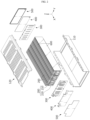
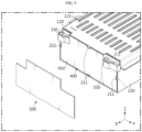
- FIG. 1 is a diagram illustrating a battery module according to an embodiment of the present disclosure.
- FIG. 2 is an exploded view showing some components of the battery module according to an embodiment of the present disclosure.
- the battery module according to an embodiment of the present disclosure may include a case 100, a plurality of battery cells 200, a bus bar frame assembly 300, and an end cover 500 or an insulation cover 400.
- the case 100 may include an upper case 120 and a lower case 110.
- the upper case 120 and the lower case 110 may be fastened, coupled, fixed, or attached.
- the case 100 may have a rectangular parallelepiped shape.
- the case 100 may have a shape where the front side and rear side are open.
- the case 100 may provide an inner space. Also, the case 100 may be formed integrally.
- the case 100 may include a metal material.
- the plurality of battery cells 200 may be accommodated in the case 100.
- the battery cell 200 may mean a secondary battery.
- the battery cell 200 may be a pouch-type secondary battery.
- the plurality of battery cells 200 may be stacked in left and right directions.
- the battery cell 200 may include a body 210 and an electrode lead 220 protruding from the body 210 in front and rear directions.
- the electrode lead 220 may be provided at the front and rear sides of the body 210, respectively.
- the battery module may additionally include a barrier 600.
- the barrier 600 may be disposed between the plurality of battery cells 200. Also, the barrier 600 may partition the plurality of battery cells 200. The barrier 600 may delay or prevent the propagation of flame, heat, gas, sparks, etc. when a thermal event occurs.
- the insulation cover 400 may be coupled with the bus bar 320, 330 to electrically insulate the end cover 500 and the bus bar frame assembly 300.
- the insulation cover 400 of the battery module may include a mica material.
- the insulation cover 400 may be formed by processing a mica sheet at high temperature or high pressure.
- the insulation cover 400 may be formed by overlapping a plurality of mica sheets and then processing them at high temperature or high pressure.
- the insulation cover 400 may be configured to have high rigidity.
- the insulation cover 400 may maintain its shape without melting or being destroyed even if a thermal event occurs. Because of this, the insulation cover 400 may stably maintain the electrical insulation state of the bus bar frame assembly 300 and the end cover 500.
- the case 100 of the battery module may have a venting hole 121 provided in the upper surface.
- the venting hole 121 may be provided in the upper case 120.
- the venting hole 121 may be provided in plurality.
- the insulation cover 400 may prevent or block venting gas or ignitable particles from being ejected in the front and rear directions of the battery module. Because of this, venting gas or ignitable particles may be discharged upward through the venting hole 121. Therefore, venting control may be facilitated by the insulation cover 400.
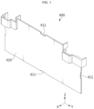
- FIG. 3 is a perspective view showing an insulation cover 400 of the battery module according to an embodiment of the present disclosure.
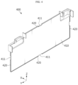
- FIG. 4 is a diagram showing the insulation cover 400 of FIG. 3 viewed in a different direction.
- FIG. 5 is an exploded view showing the insulation cover 400 of the battery module according to an embodiment of the present disclosure.
- FIG. 6 is a diagram showing the insulation cover 400 of the battery module combined according to an embodiment of the present disclosure.
- the bus bar frame assembly 300 of the battery module according to an embodiment of the present disclosure may include a frame body 310 and a bus bar 320, 330.
- the frame body 310 may be located on the front side or rear side of the plurality of battery cells 200. Also, the frame body 310 may cover the front side or rear side of the plurality of battery cells 200.
- the frame body 310 may be made of an electrically insulating material.
- the frame body 310 may include a plastic material.
- the bus bar 320, 330 may be provided on the frame body 310.
- the bus bar 320, 330 may be seated, fixed, fastened, coupled, or attached to the frame body 310.
- the bus bar 320, 330 may be provided on the front surface of the front frame body 310.
- bus bar 320, 330 may be provided on the rear surface of the rear frame body 310.
- the bus bar 320, 330 may be electrically or physically connected to the plurality of battery cells 200.
- the bus bar 320, 330 may be coupled, fastened, attached, or welded to the electrode lead 220 of the plurality of battery cells 200. At this time, the bus bar 320, 330 may be used to commonly refer to an inter bus bar 320 and a terminal bus bar 330.
- the insulation cover 400 may stably maintain the electrical insulation of the bus bar 320, 330 and the end cover 500.
- the gap between the insulation cover 400 and the end cover 500 may be reduced.
- the insulation cover 400 and the end cover 500 may be in close contact. Because of this, the energy density of the battery module may be improved.
- the fastening, fixing, coupling, and attachment structure of the insulation cover 400 and the bus bar frame assembly 300 may be damaged due to the ejected venting gas (g) and ignitable particles (f). Also, when a thermal event occurs, the bus bar 320, 330 may be separated from the frame body 310, and the bus bar 320, 330 may move toward the end cover 500.
- the insulation cover 400 of the battery module may include an insulation plate 410 having a flat plate shape and a second support 420 protruding rearward from the edge of the insulation plate 410.
- the second support 420 may extend along the perimeter of the insulation cover 400.
- the first support 520 of the end cover 500 may face the second support 420.
- the portion of the end cover 500 that supports the insulation cover 400 may be expanded.
- the contact area between the end cover 500 and the insulation cover 400 may be expanded. Because of this, the insulation cover 400 may be supported more stably by the end cover 500.
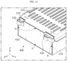
- FIG. 16 is a diagram showing some components of a battery module according to another embodiment of the present disclosure.
- the battery module according to another embodiment of the present disclosure may further include a fastening member b that couples the insulation cover 400 to the bus bar frame assembly 300.
- the fastening member b may penetrate the insulation plate 410 of the insulation cover 400.
- the fastening member b may be fastened to the frame body 310.
- the fastening member b may include an electrically insulating material.
- the fastening member b may be provided in plurality.
- the fastening member b may be provided on the upper, lower, left, and right sides.
- the insulation cover 400 may be stably coupled, fastened, or fixed to the frame body 310. Also, because the fastening member b has electric insulation, electrical safety may be maintained even if the fastening member b separates and moves due to a thermal event.
- FIG. 17 is an exploded view showing some components of the battery module according to still another embodiment of the present disclosure.
- FIG. 18 is a diagram showing a modified example of FIG. 14 .
- the battery module according to still another embodiment of the present disclosure may further include an adhesion member 700 disposed between the end cover 500 and the insulation cover 400.
- the adhesion member 700 may fix the insulation cover 400 to the end cover 500.
- the adhesion member 700 may be provided on the front surface of the insulation plate 410. Alternatively, the adhesion member 700 may be provided on the rear surface of the end plate 510.
- a battery pack according to the present disclosure may include the battery module according to the present disclosure described above.
- the battery pack according to the present disclosure may further include various other components in addition to the battery module according to the present disclosure, for example components of a battery pack known at the time of filing of this application, such as a BMS, a bus bar, a pack case, a relay, a current sensor, etc.
- the battery module and the battery pack may not be strictly distinct terms, and in some cases, the battery module and the battery pack may be used with the same meaning.
- a battery pack that does not include a BMS may mean a battery module.
- the battery module when the battery module functions as a battery pack, the battery module may mean a battery pack.
- a vehicle according to the present disclosure may include the battery module according to the present disclosure described above.
- the battery module according to the present disclosure may be applied to vehicles such as electric vehicles or hybrid vehicles.
- the vehicle according to the present disclosure may further include various other components included in a vehicle, such as a body, a motor, and a control device like an ECU (electronic control unit), in addition to the battery module.
- ECU electronic control unit
Landscapes
- Chemical & Material Sciences (AREA)
- Chemical Kinetics & Catalysis (AREA)
- Electrochemistry (AREA)
- General Chemical & Material Sciences (AREA)
- Engineering & Computer Science (AREA)
- Aviation & Aerospace Engineering (AREA)
- Battery Mounting, Suspending (AREA)
- Connection Of Batteries Or Terminals (AREA)
- Gas Exhaust Devices For Batteries (AREA)
Abstract
Description
- The present disclosure relates to a battery module.
- The present application claims priority to
Korean Patent Application No. 10-2023-0096978 filed on July 25, 2023 - As the demand for portable electronic products such as laptops, video cameras, and portable phones is rapidly increasing, and robots, electric vehicles, or the like are commercialized in earnest, research on high-performance secondary batteries capable of repeated charging and discharging is actively underway.
- Currently, commercially available secondary batteries include nickel-cadmium batteries, nickel-hydrogen batteries, nickel-zinc batteries, lithium secondary batteries and the like, and among them, lithium secondary batteries have little or no memory effect, and thus they are gaining more attention than nickel-based secondary batteries for their advantages that recharging can be done whenever it is convenient, the self-discharge rate is very low and the energy density is high.
- Lithium secondary batteries primarily comprise lithium-based oxides and carbon materials for a positive electrode active material and a negative electrode active material, respectively. A lithium secondary battery includes an electrode assembly including a positive electrode plate and a negative electrode plate coated with the positive electrode active material and the negative electrode active material, respectively, with a separator interposed between the positive electrode plate and the negative electrode plate, and a sealed packaging or battery case accommodating the electrode assembly together with an electrolyte solution.
- In general, lithium secondary batteries may be classified into can-type secondary batteries in which the electrode assembly is included in a metal can and pouch-type secondary batteries in which the electrode assembly is included in a pouch of an aluminum laminate sheet, according to the shape of the battery case.
- Recently, secondary batteries have been widely used in medium and large devices such as electric vehicles and energy storage systems (ESSs) for driving and storing energy, as well as in small devices such as portable electronic devices. A plurality of secondary batteries may be electrically connected and stored inside a module case, thereby forming a battery module. In addition, multiple battery modules may be connected to each other to form a battery pack.
- However, if a plurality of secondary batteries (battery cells) or a plurality of battery modules are crowded in a small space, they may be vulnerable to thermal events. In particular, if an event such as thermal runaway occurs in one battery cell, high temperature gas, flame, or heat may be generated. If the gases, flames, heat, etc. is transferred to other battery cells included in the same battery module, an explosive chain reaction situation such as thermal propagation may occur. Also, this chain reaction not only causes accidents such as fire or explosion in the corresponding battery module, but may also cause fire or explosion in other battery modules.
- Moreover, in the case of medium to large-sized battery packs such as electric vehicles, a large number of battery cells and battery modules are included to increase output and/or capacity, so the risk of thermal chain reaction may increase further. Furthermore, in the case of a battery pack mounted on an electric vehicle, etc., users such as drivers may be present nearby. Therefore, if a thermal event occurring in a specific battery module is not properly controlled and a chain reaction occurs, it may cause not only significant property damage but also loss of life.
- In addition, if a thermal event occurs, it is important to increase electrical safety by preventing current from being leaked as power of the battery cell is short-circuited with adjacent components even.
- The present disclosure is designed to solve these and other problems.
- The present disclosure is directed to providing a battery module with improved electrical safety when a thermal event occurs.
- The present disclosure is also directed to providing a battery module that includes a structure that may maintain the electrical insulation state between an end cover and a battery cell when a thermal event occurs.
- The present disclosure is also directed to providing a battery module that facilitates venting control when a thermal event occurs.
- In one aspect of the present disclosure, there is provided a battery module, comprising: a case having an open front side and providing an inner space; a plurality of battery cells accommodated in the case; a bus bar frame assembly electrically connected to the plurality of battery cells and located on a front side of the plurality of battery cells; an end cover coupled to the open front side of the case; and an insulation cover located between the bus bar frame assembly and the end cover and coupled with the bus bar frame assembly.
- In addition, the insulation cover may include a mica material.
- In addition, the case may have a venting hole provided in an upper surface thereof.
- In addition, the bus bar frame assembly may include a frame body configured to cover the front side of the case; and a bus bar provided on a front surface of the frame body and electrically connected to the battery cell, and the insulation cover may cover a front side of the bus bar entirely.
- In addition, the bus bar frame assembly may include a hook that protrudes forward, and the insulation cover may be coupled to the hook.
- In addition, the insulation cover may include an insulation plate having a flat plate shape; and, a hooking groove formed inward from one edge of the insulation plate, and the hook may pass through the hooking groove and be caught on a front surface of the insulation plate.
- In addition, the end cover may have an accommodation portion formed on a rear surface thereof, and at least a part of the hook may be accommodated in the accommodation portion.
- In addition, the battery module may further comprise a fastening member configured to couple the insulation cover to the bus bar frame assembly.
- In addition, the end cover may be configured to support the insulation cover.
- In addition, the end cover may include a first support that protrudes rearward, and the first support may cover a side of the insulation cover.
- In addition, the insulation cover may include an insulation plate having a flat plate shape; and a second support configured to protrude rearward from an edge of the insulation plate, and the first support may be configured to face the second support.
- In addition, the battery module may further comprise an adhesion member disposed between the end cover and the insulation cover.
- A battery pack according to one aspect of the present disclosure may include the battery module of the present disclosure.
- A vehicle according to another aspect of the present disclosure may include the battery module of the present disclosure.
- According to at least one of the embodiments of the present disclosure, the electrical safety of the battery module may be improved.
- According to at least one of the embodiments of the present disclosure, venting control of the battery module may be facilitated.
- The accompanying drawings illustrate a preferred embodiment of the present disclosure and together with the foregoing disclosure, serve to provide further understanding of the technical features of the present disclosure, and thus, the present disclosure is not construed as being limited to the drawing.
-
FIG. 1 is a diagram illustrating a battery module according to an embodiment of the present disclosure. -
FIG. 2 is an exploded view showing some components of the battery module according to an embodiment of the present disclosure. -
FIG. 3 is a perspective view showing an insulation cover of the battery module according to an embodiment of the present disclosure. -
FIG. 4 is a diagram showing the insulation cover ofFIG. 3 viewed in a different direction. -
FIG. 5 is an exploded view showing the insulation cover of the battery module according to an embodiment of the present disclosure. -
FIG. 6 is a diagram showing the insulation cover of the battery module combined according to an embodiment of the present disclosure. -
FIG. 7 is a perspective view showing an end cover of the battery module according to an embodiment of the present disclosure. -
FIG. 8 is a diagram showing the end cover ofFIG. 7 viewed in a different direction. -
FIG. 9 is an exploded view showing the end cover of the battery module according to an embodiment of the present disclosure. -
FIG. 10 is a diagram showing the end cover of the battery module combined according to an embodiment of the present disclosure. -
FIG. 11 is a diagram schematically showing a part of the cross-sectional configuration along the cutting line A-A' inFIG. 10 . -
FIG. 12 is a diagram schematically showing a part of the cross-sectional configuration along the cutting line B-B' inFIG. 10 . -
FIG. 13 is a diagram schematically showing a part of the cross-sectional configuration along the cutting line C-C' inFIG. 10 . -
FIG. 14 is a diagram schematically showing a part of the cross-sectional configuration along the cutting line D-D' inFIG. 10 . -
FIG. 15 is a diagram showing the change inFIG. 14 when a thermal event occurs. -
FIG. 16 is a diagram showing some components of a battery module according to another embodiment of the present disclosure. -
FIG. 17 is an exploded view showing some components of the battery module according to still another embodiment of the present disclosure. -
FIG. 18 is a diagram showing a modified example ofFIG. 14 . - Hereinafter, preferred embodiments of the present disclosure will be described in detail with reference to the accompanying drawings. Prior to the description, it should be understood that the terms used in the specification and the appended claims should not be construed as limited to general and dictionary meanings, but interpreted based on the meanings and concepts corresponding to technical aspects of the present disclosure on the basis of the principle that the inventor is allowed to define terms appropriately for the best explanation.
- Therefore, the description proposed herein is just a preferable example for the purpose of illustrations only, not intended to limit the scope of the disclosure, so it should be understood that other equivalents and modifications could be made thereto without departing from the scope of the disclosure.
-
FIG. 1 is a diagram illustrating a battery module according to an embodiment of the present disclosure.FIG. 2 is an exploded view showing some components of the battery module according to an embodiment of the present disclosure. Referring toFIGS. 1 and2 , the battery module according to an embodiment of the present disclosure may include acase 100, a plurality ofbattery cells 200, a busbar frame assembly 300, and anend cover 500 or aninsulation cover 400. - The
case 100 may include anupper case 120 and alower case 110. Theupper case 120 and thelower case 110 may be fastened, coupled, fixed, or attached. Thecase 100 may have a rectangular parallelepiped shape. Thecase 100 may have a shape where the front side and rear side are open. Thecase 100 may provide an inner space. Also, thecase 100 may be formed integrally. Thecase 100 may include a metal material. - The plurality of
battery cells 200 may be accommodated in thecase 100. At this time, thebattery cell 200 may mean a secondary battery. Thebattery cell 200 may be a pouch-type secondary battery. The plurality ofbattery cells 200 may be stacked in left and right directions. Thebattery cell 200 may include abody 210 and anelectrode lead 220 protruding from thebody 210 in front and rear directions. Theelectrode lead 220 may be provided at the front and rear sides of thebody 210, respectively. - The battery module may additionally include a
barrier 600. Thebarrier 600 may be disposed between the plurality ofbattery cells 200. Also, thebarrier 600 may partition the plurality ofbattery cells 200. Thebarrier 600 may delay or prevent the propagation of flame, heat, gas, sparks, etc. when a thermal event occurs. - The bus
bar frame assembly 300 may be electrically connected to the plurality ofbattery cells 200. The busbar frame assembly 300 may be provided as a pair. The busbar frame assembly 300 may be provided on the front side and the rear side of the plurality ofbattery cells 200, respectively. The pair of busbar frame assemblies 300 may be electrically connected to the plurality ofbattery cells 200, respectively. - The
end cover 500 may be provided as a pair. Theend cover 500 may be coupled, fastened, or fixed to the open front side of thecase 100. Also, theend cover 500 may be coupled, fastened, or fixed to the open rear side of thecase 100. At this time, theend cover 500 and thecase 100 may be coupled through welding. Theend cover 500 may include a metal material. - The
insulation cover 400 may be provided as a pair. Theinsulation cover 400 may be located between the busbar frame assembly 300 and theend cover 500. The pair of insulation covers 400 may be coupled, fastened, attached, or fixed to the busbar frame assembly 300, respectively. - According to this configuration of the present disclosure, the
insulation cover 400 may be coupled with thebus bar end cover 500 and the busbar frame assembly 300. - Referring to
FIGS. 1 and2 , theinsulation cover 400 of the battery module according to an embodiment of the present disclosure may include a mica material. At this time, theinsulation cover 400 may be formed by processing a mica sheet at high temperature or high pressure. Also, theinsulation cover 400 may be formed by overlapping a plurality of mica sheets and then processing them at high temperature or high pressure. Theinsulation cover 400 may be configured to have high rigidity. - According to this configuration of the present disclosure, the
insulation cover 400 may maintain its shape without melting or being destroyed even if a thermal event occurs. Because of this, theinsulation cover 400 may stably maintain the electrical insulation state of the busbar frame assembly 300 and theend cover 500. - Referring to
FIGS. 1 and2 , thecase 100 of the battery module according to an embodiment of the present disclosure may have aventing hole 121 provided in the upper surface. Theventing hole 121 may be provided in theupper case 120. Theventing hole 121 may be provided in plurality. - According to this configuration of the present disclosure, even if a thermal event occurs, the
insulation cover 400 may prevent or block venting gas or ignitable particles from being ejected in the front and rear directions of the battery module. Because of this, venting gas or ignitable particles may be discharged upward through theventing hole 121. Therefore, venting control may be facilitated by theinsulation cover 400. -
FIG. 3 is a perspective view showing aninsulation cover 400 of the battery module according to an embodiment of the present disclosure.FIG. 4 is a diagram showing theinsulation cover 400 ofFIG. 3 viewed in a different direction.FIG. 5 is an exploded view showing theinsulation cover 400 of the battery module according to an embodiment of the present disclosure.FIG. 6 is a diagram showing theinsulation cover 400 of the battery module combined according to an embodiment of the present disclosure. Referring toFIGS. 3 to 6 , the busbar frame assembly 300 of the battery module according to an embodiment of the present disclosure may include aframe body 310 and abus bar - The
frame body 310 may be located on the front side or rear side of the plurality ofbattery cells 200. Also, theframe body 310 may cover the front side or rear side of the plurality ofbattery cells 200. Theframe body 310 may be made of an electrically insulating material. For example, theframe body 310 may include a plastic material. - The
bus bar frame body 310. Thebus bar frame body 310. Thebus bar front frame body 310. Also,bus bar rear frame body 310. Thebus bar battery cells 200. Thebus bar electrode lead 220 of the plurality ofbattery cells 200. At this time, thebus bar inter bus bar 320 and aterminal bus bar 330. Theterminal bus bar 330 may output power from the battery module and receive external power. Theterminal bus bar 330 may be electrically or physically connected to an external device. Theterminal bus bar 330 may be provided as a pair. Theinter bus bar 320 may be located between the pair of terminal bus bars 330. Theinter bus bar 320 may be provided in plurality. - The
insulation cover 400 may cover the front side of thebus bar bar frame assembly 300. Because of this, thebus bar bar frame assembly 300 may not be exposed to the outside. Also, theinsulation cover 400 may entirely cover the rear side of thebus bar bar frame assembly 300. Because of this, thebus bar bar frame assembly 300 may not be exposed to the outside. - According to this configuration of the present disclosure, the
insulation cover 400 may stably maintain the electrical insulation of thebus bar end cover 500. - Hereinafter, the present disclosure will be described based on the front bus
bar frame assembly 300, theinsulation cover 400, and theend cover 500. Referring toFIGS. 3 to 6 , the busbar frame assembly 300 of the battery module according to an embodiment of the present disclosure may include ahook 211 protruding forward. Thehook 211 may protrude from theframe body 310. Thehook 211 may be made of the same material as theframe body 310. Also, thehook 211 may be provided in plurality. Theinsulation cover 400 may be coupled, fastened, or fixed to thehook 211. Theinsulation cover 400 may be coupled, fastened, or fixed to the plurality ofhooks 211. - According to this configuration of the present disclosure, the
insulation cover 400 may be stably fixed in position. Theinsulation cover 400 may contain a mica material with high rigidity, and machining theinsulation cover 400 into shape may be very limited. For example, forming a hook on theinsulation cover 400 may be very limited. Also, if theend cover 500 is made of a metal material, shape processing may be very limited. For example, forming a hook on theend cover 500 may be very limited. Therefore, it may be desirable to form thehook 211 on theframe body 310 made of a material that is easy to form. By forming thehook 211 on theframe body 310, productivity and assembly of the battery module may be improved. - Referring to
FIGS. 3 to 6 , theinsulation cover 400 of the battery module according to an embodiment of the present disclosure may include aninsulation plate 410 and a hookinggroove 411. Theinsulation plate 410 may have a flat plate shape. Also, theinsulation plate 410 may have a rectangular shape as a whole. The hookinggroove 411 may be formed inward from one edge of theinsulation plate 410. The hookinggroove 411 may be formed to penetrate theinsulation plate 410. Thehook 211 may pass through the hookinggroove 411 and be caught on the front surface of theinsulation plate 410. The hookinggroove 411 may be provided in plurality. The hookinggroove 411 may be provided to correspond to thehook 211 in one-to-one relationship. For example, four hookinggrooves 411 and fourhooks 211 may be provided, and thehooks 211 may be provided on the upper, lower, left, and right sides of theframe body 310, respectively. Thebus bar hooks 211. - According to this configuration of the present disclosure, the
insulation cover 400 and the busbar frame assembly 300 may be stably coupled. -
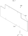
FIG. 7 is a perspective view showing anend cover 500 of the battery module according to an embodiment of the present disclosure.FIG. 8 is a diagram showing theend cover 500 ofFIG. 7 viewed in a different direction.FIG. 9 is an exploded view showing theend cover 500 of the battery module according to an embodiment of the present disclosure.FIG. 10 is a diagram showing theend cover 500 of the battery module combined according to an embodiment of the present disclosure. Referring toFIGS. 7 to 10 , theend cover 500 according to an embodiment of the present disclosure may include anend plate 510 having a flat plate shape. - The
end cover 500 may include afirst support 520 protruding from the rear surface of theend plate 510. Also, theend cover 500 may include anaccommodation portion 511 formed on the rear surface. Theaccommodation portion 511 may be formed inside thefirst support 520. Theaccommodation portion 511 may be a groove. Theaccommodation portion 511 may not penetrate theend cover 500. Theaccommodation portion 511 may be provided in plurality. The plurality ofaccommodation portions 511 may be provided to correspond to thehooks 211 in one-to-one relationship. Also, the plurality ofaccommodation portions 511 may be positioned to correspond to thehooks 211. When theend cover 500 and thecase 100 are coupled, at least a part of thehook 211 may be accommodated or inserted into theaccommodation portion 511. - According to this configuration of the present disclosure, the gap between the
insulation cover 400 and theend cover 500 may be reduced. Alternatively, theinsulation cover 400 and theend cover 500 may be in close contact. Because of this, the energy density of the battery module may be improved. - Conventionally, a through hole is formed in the
end cover 500 and theinsulation cover 400 is fastened to the through hole. Because of this, when a thermal event occurs, there is a risk that venting gas or ignitable particles can be ejected through the through hole of theend cover 500. - Meanwhile, according to this configuration of the present disclosure, the
end cover 500 does not have a through hole, so that venting gas or ignitable particles can be blocked from being ejected through theend cover 500 even if a thermal event occurs. Because of this, venting gas or ignitable particles can be discharged upward through theventing hole 121. Therefore, venting control may be facilitated by theend cover 500. -
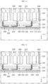
FIG. 11 is a diagram schematically showing a part of the cross-sectional configuration along the cutting line A-A' inFIG. 10 .FIG. 12 is a diagram schematically showing a part of the cross-sectional configuration along the cutting line B-B' inFIG. 10 .FIG. 13 is a diagram schematically showing a part of the cross-sectional configuration along the cutting line C-C' inFIG. 10 .FIG. 14 is a diagram schematically showing a part of the cross-sectional configuration along the cutting line D-D' inFIG. 10 .FIG. 15 is a diagram showing the change inFIG. 14 when a thermal event occurs. - Referring to
FIGS. 10 to 15 , theend cover 500 of the battery module according to an embodiment of the present disclosure may be configured to support theinsulation cover 400. Theend cover 500 may be in close contact with or located close to theinsulation cover 400. - According to this configuration of the present disclosure, when a thermal event occurs, the fastening, fixing, coupling, and attachment structure of the
insulation cover 400 and the busbar frame assembly 300 may be damaged. By supporting theinsulation cover 400, theend cover 500 may support the position of theinsulation cover 400 not to be distorted. Because of this, the electrical and thermal safety of the battery module may be improved. - Referring to
FIGS. 10 to 15 , theend cover 500 of the battery module according to an embodiment of the present disclosure may include afirst support 520 protruding rearward. Thefirst support 520 may extend along the perimeter of theend cover 500. Thefirst support 520 may cover the perimeter, side or edge of theinsulation cover 400. Also, at least a part of thehook 211 may be inserted into theaccommodation portion 511. Theaccommodation portion 511 may be located inside thefirst support 520. Also, thehook 211 may be located inside thefirst support 520. - Referring to
FIG. 15 , when a thermal event occurs, the fastening, fixing, coupling, and attachment structure of theinsulation cover 400 and the busbar frame assembly 300 may be damaged due to the ejected venting gas (g) and ignitable particles (f). Also, when a thermal event occurs, thebus bar frame body 310, and thebus bar end cover 500. - According to this configuration of the present disclosure, the
first support 520 of theend plate 510 supports theinsulation cover 400, so that the position of theinsulation cover 400 is not distorted. Because of this, theinsulation cover 400 may block theend cover 500 and thebus bar - Referring to
FIGS. 10 to 15 , theinsulation cover 400 of the battery module according to an embodiment of the present disclosure may include aninsulation plate 410 having a flat plate shape and asecond support 420 protruding rearward from the edge of theinsulation plate 410. Thesecond support 420 may extend along the perimeter of theinsulation cover 400. Thefirst support 520 of theend cover 500 may face thesecond support 420. - According to this configuration of the present disclosure, the portion of the
end cover 500 that supports theinsulation cover 400 may be expanded. Alternatively, the contact area between theend cover 500 and theinsulation cover 400 may be expanded. Because of this, theinsulation cover 400 may be supported more stably by theend cover 500. -
FIG. 16 is a diagram showing some components of a battery module according to another embodiment of the present disclosure. Referring toFIG. 16 , the battery module according to another embodiment of the present disclosure may further include a fastening member b that couples theinsulation cover 400 to the busbar frame assembly 300. The fastening member b may penetrate theinsulation plate 410 of theinsulation cover 400. Also, the fastening member b may be fastened to theframe body 310. The fastening member b may include an electrically insulating material. Also, the fastening member b may be provided in plurality. The fastening member b may be provided on the upper, lower, left, and right sides. - According to this configuration of the present disclosure, the
insulation cover 400 may be stably coupled, fastened, or fixed to theframe body 310. Also, because the fastening member b has electric insulation, electrical safety may be maintained even if the fastening member b separates and moves due to a thermal event. -
FIG. 17 is an exploded view showing some components of the battery module according to still another embodiment of the present disclosure.FIG. 18 is a diagram showing a modified example ofFIG. 14 . Referring toFIGS. 14 ,17 , and18 , the battery module according to still another embodiment of the present disclosure may further include anadhesion member 700 disposed between theend cover 500 and theinsulation cover 400. Theadhesion member 700 may fix theinsulation cover 400 to theend cover 500. Theadhesion member 700 may be provided on the front surface of theinsulation plate 410. Alternatively, theadhesion member 700 may be provided on the rear surface of theend plate 510. - According to this configuration of the present disclosure, the portion of the
end cover 500 that supports theinsulation cover 400 may be expanded. Alternatively, the bonding strength between theend cover 500 and theinsulation cover 400 may be strengthened. Because of this, theinsulation cover 400 may be supported more stably by theend cover 500. - A battery pack according to the present disclosure may include the battery module according to the present disclosure described above. In addition, the battery pack according to the present disclosure may further include various other components in addition to the battery module according to the present disclosure, for example components of a battery pack known at the time of filing of this application, such as a BMS, a bus bar, a pack case, a relay, a current sensor, etc.
- Meanwhile, the battery module and the battery pack may not be strictly distinct terms, and in some cases, the battery module and the battery pack may be used with the same meaning. For example, a battery pack that does not include a BMS may mean a battery module. Also, considering an embodiment of the battery module, when the battery module functions as a battery pack, the battery module may mean a battery pack.
- A vehicle according to the present disclosure may include the battery module according to the present disclosure described above. The battery module according to the present disclosure may be applied to vehicles such as electric vehicles or hybrid vehicles. In addition, the vehicle according to the present disclosure may further include various other components included in a vehicle, such as a body, a motor, and a control device like an ECU (electronic control unit), in addition to the battery module.
- The terms indicating directions such as upper, lower, left, right, front and rear are used for convenience of description, but it is obvious to those skilled in the art that the terms may change depending on the position of the stated element or an observer.
- The present disclosure has been described in detail. However, it should be understood that the detailed description and specific examples, while indicating preferred embodiments of the disclosure, are given by way of illustration only, since various changes and modifications within the scope of the disclosure will become apparent to those skilled in the art from this detailed description.
Claims (14)
- A battery module, comprising:a case having an open front side and providing an inner space;a plurality of battery cells accommodated in the case;a bus bar frame assembly electrically connected to the plurality of battery cells and located on a front side of the plurality of battery cells;an end cover coupled to the open front side of the case; andan insulation cover located between the bus bar frame assembly and the end cover and coupled with the bus bar frame assembly.
- The battery module according to claim 1,
wherein the insulation cover includes a mica material. - The battery module according to claim 1,
wherein the case has a venting hole provided in an upper surface thereof. - The battery module according to claim 1,
wherein the bus bar frame assembly includes:a frame body configured to cover the front side of the case; anda bus bar provided on a front surface of the frame body and electrically connected to the battery cell,wherein the insulation cover covers a front side of the bus bar entirely. - The battery module according to claim 1,wherein the bus bar frame assembly includes a hook that protrudes forward, andwherein the insulation cover is coupled to the hook.
- The battery module according to claim 5,
wherein the insulation cover includes:an insulation plate having a flat plate shape; and,a hooking groove formed inward from one edge of the insulation plate,wherein the hook passes through the hooking groove and is caught on a front surface of the insulation plate. - The battery module according to claim 5,wherein the end cover has an accommodation portion formed on a rear surface thereof, andwherein at least a part of the hook is accommodated in the accommodation portion.
- The battery module according to claim 1, further comprising:
a fastening member configured to couple the insulation cover to the bus bar frame assembly. - The battery module according to claim 1,
wherein the end cover is configured to support the insulation cover. - The battery module according to claim 1,wherein the end cover includes a first support that protrudes rearward, andwherein the first support covers a side of the insulation cover.
- The battery module according to claim 10,
wherein the insulation cover includes:an insulation plate having a flat plate shape; and,a second support configured to protrude rearward from an edge of the insulation plate,wherein the first support is configured to face the second support. - The battery module according to claim 1, further comprising:
an adhesion member disposed between the end cover and the insulation cover. - A battery pack, comprising the battery module according to any one of claims 1 to 12.
- A vehicle, comprising the battery module according to any one of claims 1 to 12.
Applications Claiming Priority (2)
| Application Number | Priority Date | Filing Date | Title |
|---|---|---|---|
| KR1020230096978A KR20250015487A (en) | 2023-07-25 | 2023-07-25 | Battery module |
| PCT/KR2024/005414 WO2025023427A1 (en) | 2023-07-25 | 2024-04-22 | Battery module |
Publications (2)
| Publication Number | Publication Date |
|---|---|
| EP4579939A1 true EP4579939A1 (en) | 2025-07-02 |
| EP4579939A4 EP4579939A4 (en) | 2025-12-31 |
Family
ID=94374923
Family Applications (1)
| Application Number | Title | Priority Date | Filing Date |
|---|---|---|---|
| EP24845731.9A Pending EP4579939A4 (en) | 2023-07-25 | 2024-04-22 | BATTERY MODULE |
Country Status (5)
| Country | Link |
|---|---|
| EP (1) | EP4579939A4 (en) |
| JP (1) | JP2026502376A (en) |
| KR (1) | KR20250015487A (en) |
| CN (1) | CN119866574A (en) |
| WO (1) | WO2025023427A1 (en) |
Family Cites Families (9)
| Publication number | Priority date | Publication date | Assignee | Title |
|---|---|---|---|---|
| US11376969B2 (en) * | 2016-12-27 | 2022-07-05 | Yura Corporation Co., Ltd. | Bus bar assembly and frame assembly |
| KR102033003B1 (en) * | 2017-02-28 | 2019-10-16 | 주식회사 유라코퍼레이션 | Frame assembly |
| KR102772770B1 (en) * | 2019-10-14 | 2025-02-24 | 주식회사 엘지에너지솔루션 | Battery module and battery pack including the same |
| EP4205216A4 (en) | 2020-08-28 | 2025-02-19 | EOS Energy Technology Holdings, LLC | Terminal assembly and battery frame member for rechargeable battery |
| WO2022114529A1 (en) * | 2020-11-30 | 2022-06-02 | 주식회사 엘지에너지솔루션 | Battery module and battery pack including same |
| CN113067107A (en) * | 2021-03-23 | 2021-07-02 | 远景动力技术(江苏)有限公司 | Busbar subassembly, battery module and vehicle |
| KR102638290B1 (en) * | 2021-12-03 | 2024-02-19 | 에스케이온 주식회사 | Flame blocking unit and Battery pack |
| EP4657634A1 (en) * | 2021-12-16 | 2025-12-03 | LG Energy Solution, Ltd. | Battery module having improved safety |
| KR102674209B1 (en) * | 2021-12-30 | 2024-06-12 | 에스케이온 주식회사 | Battery module and battery pack comprising the same |
-
2023
- 2023-07-25 KR KR1020230096978A patent/KR20250015487A/en active Pending
-
2024
- 2024-04-22 EP EP24845731.9A patent/EP4579939A4/en active Pending
- 2024-04-22 WO PCT/KR2024/005414 patent/WO2025023427A1/en active Pending
- 2024-04-22 JP JP2025538018A patent/JP2026502376A/en active Pending
- 2024-04-22 CN CN202480003896.0A patent/CN119866574A/en active Pending
Also Published As
| Publication number | Publication date |
|---|---|
| EP4579939A4 (en) | 2025-12-31 |
| CN119866574A (en) | 2025-04-22 |
| KR20250015487A (en) | 2025-02-03 |
| JP2026502376A (en) | 2026-01-22 |
| WO2025023427A1 (en) | 2025-01-30 |
Similar Documents
| Publication | Publication Date | Title |
|---|---|---|
| EP3340338B1 (en) | Battery module | |
| EP3512008B1 (en) | Battery module, and battery pack and vehicle including the same | |
| EP4404361A1 (en) | Battery pack and device including same | |
| EP4401218A1 (en) | Battery module | |
| EP4401213A1 (en) | Battery sub-module | |
| EP4685933A1 (en) | Battery pack | |
| EP4576385A1 (en) | Battery module | |
| KR20250038076A (en) | Battery pack | |
| KR20240012317A (en) | Battery pack and device including the same | |
| EP4661179A1 (en) | Battery assembly | |
| EP4730490A1 (en) | Battery pack | |
| EP4632905A1 (en) | Battery assembly | |
| EP4712243A1 (en) | Battery pack | |
| EP4675817A1 (en) | Battery pack | |
| EP4730537A1 (en) | Battery pack | |
| CN119866574A (en) | Battery Module | |
| EP4629423A1 (en) | Battery pack | |
| EP4708456A1 (en) | Battery pack | |
| US20250226516A1 (en) | Battery Assembly | |
| EP4468499A1 (en) | Battery module, and battery pack and vehicle comprising same | |
| EP4579911A1 (en) | Battery module, and battery pack and vehicle comprising same | |
| EP4708497A2 (en) | Battery pack and energy storage system including same | |
| EP4685966A1 (en) | Battery assembly | |
| EP4734219A1 (en) | Battery pack | |
| EP4700936A1 (en) | Battery assembly |
Legal Events
| Date | Code | Title | Description |
|---|---|---|---|
| STAA | Information on the status of an ep patent application or granted ep patent |
Free format text: STATUS: THE INTERNATIONAL PUBLICATION HAS BEEN MADE |
|
| PUAI | Public reference made under article 153(3) epc to a published international application that has entered the european phase |
Free format text: ORIGINAL CODE: 0009012 |
|
| STAA | Information on the status of an ep patent application or granted ep patent |
Free format text: STATUS: REQUEST FOR EXAMINATION WAS MADE |
|
| 17P | Request for examination filed |
Effective date: 20250324 |
|
| AK | Designated contracting states |
Kind code of ref document: A1 Designated state(s): AL AT BE BG CH CY CZ DE DK EE ES FI FR GB GR HR HU IE IS IT LI LT LU LV MC ME MK MT NL NO PL PT RO RS SE SI SK SM TR |
|
| A4 | Supplementary search report drawn up and despatched |
Effective date: 20251203 |
|
| RIC1 | Information provided on ipc code assigned before grant |
Ipc: H01M 50/593 20210101AFI20251127BHEP Ipc: H01M 50/588 20210101ALI20251127BHEP Ipc: H01M 50/30 20210101ALI20251127BHEP Ipc: H01M 50/502 20210101ALI20251127BHEP Ipc: H01M 50/211 20210101ALI20251127BHEP Ipc: H01M 50/249 20210101ALI20251127BHEP Ipc: H01M 50/209 20210101ALI20251127BHEP Ipc: H01M 50/271 20210101ALI20251127BHEP Ipc: H01M 50/507 20210101ALI20251127BHEP |