EP4579934A1 - Battery pack connector and battery pack - Google Patents
Battery pack connector and battery pack Download PDFInfo
- Publication number
- EP4579934A1 EP4579934A1 EP24205906.1A EP24205906A EP4579934A1 EP 4579934 A1 EP4579934 A1 EP 4579934A1 EP 24205906 A EP24205906 A EP 24205906A EP 4579934 A1 EP4579934 A1 EP 4579934A1
- Authority
- EP
- European Patent Office
- Prior art keywords
- battery pack
- hole
- boss
- connector
- insulation base
- Prior art date
- Legal status (The legal status is an assumption and is not a legal conclusion. Google has not performed a legal analysis and makes no representation as to the accuracy of the status listed.)
- Pending
Links
Images




Classifications
-
- H—ELECTRICITY
- H01—ELECTRIC ELEMENTS
- H01M—PROCESSES OR MEANS, e.g. BATTERIES, FOR THE DIRECT CONVERSION OF CHEMICAL ENERGY INTO ELECTRICAL ENERGY
- H01M50/00—Constructional details or processes of manufacture of the non-active parts of electrochemical cells other than fuel cells, e.g. hybrid cells
- H01M50/50—Current conducting connections for cells or batteries
- H01M50/502—Interconnectors for connecting terminals of adjacent batteries; Interconnectors for connecting cells outside a battery casing
- H01M50/514—Methods for interconnecting adjacent batteries or cells
- H01M50/517—Methods for interconnecting adjacent batteries or cells by fixing means, e.g. screws, rivets or bolts
-
- H—ELECTRICITY
- H01—ELECTRIC ELEMENTS
- H01M—PROCESSES OR MEANS, e.g. BATTERIES, FOR THE DIRECT CONVERSION OF CHEMICAL ENERGY INTO ELECTRICAL ENERGY
- H01M50/00—Constructional details or processes of manufacture of the non-active parts of electrochemical cells other than fuel cells, e.g. hybrid cells
- H01M50/50—Current conducting connections for cells or batteries
- H01M50/543—Terminals
-
- H—ELECTRICITY
- H01—ELECTRIC ELEMENTS
- H01M—PROCESSES OR MEANS, e.g. BATTERIES, FOR THE DIRECT CONVERSION OF CHEMICAL ENERGY INTO ELECTRICAL ENERGY
- H01M50/00—Constructional details or processes of manufacture of the non-active parts of electrochemical cells other than fuel cells, e.g. hybrid cells
- H01M50/20—Mountings; Secondary casings or frames; Racks, modules or packs; Suspension devices; Shock absorbers; Transport or carrying devices; Holders
- H01M50/204—Racks, modules or packs for multiple batteries or multiple cells
- H01M50/207—Racks, modules or packs for multiple batteries or multiple cells characterised by their shape
- H01M50/209—Racks, modules or packs for multiple batteries or multiple cells characterised by their shape adapted for prismatic or rectangular cells
-
- H—ELECTRICITY
- H01—ELECTRIC ELEMENTS
- H01M—PROCESSES OR MEANS, e.g. BATTERIES, FOR THE DIRECT CONVERSION OF CHEMICAL ENERGY INTO ELECTRICAL ENERGY
- H01M50/00—Constructional details or processes of manufacture of the non-active parts of electrochemical cells other than fuel cells, e.g. hybrid cells
- H01M50/50—Current conducting connections for cells or batteries
- H01M50/543—Terminals
- H01M50/552—Terminals characterised by their shape
- H01M50/553—Terminals adapted for prismatic, pouch or rectangular cells
-
- H—ELECTRICITY
- H01—ELECTRIC ELEMENTS
- H01M—PROCESSES OR MEANS, e.g. BATTERIES, FOR THE DIRECT CONVERSION OF CHEMICAL ENERGY INTO ELECTRICAL ENERGY
- H01M50/00—Constructional details or processes of manufacture of the non-active parts of electrochemical cells other than fuel cells, e.g. hybrid cells
- H01M50/50—Current conducting connections for cells or batteries
- H01M50/543—Terminals
- H01M50/562—Terminals characterised by the material
-
- Y—GENERAL TAGGING OF NEW TECHNOLOGICAL DEVELOPMENTS; GENERAL TAGGING OF CROSS-SECTIONAL TECHNOLOGIES SPANNING OVER SEVERAL SECTIONS OF THE IPC; TECHNICAL SUBJECTS COVERED BY FORMER USPC CROSS-REFERENCE ART COLLECTIONS [XRACs] AND DIGESTS
- Y02—TECHNOLOGIES OR APPLICATIONS FOR MITIGATION OR ADAPTATION AGAINST CLIMATE CHANGE
- Y02E—REDUCTION OF GREENHOUSE GAS [GHG] EMISSIONS, RELATED TO ENERGY GENERATION, TRANSMISSION OR DISTRIBUTION
- Y02E60/00—Enabling technologies; Technologies with a potential or indirect contribution to GHG emissions mitigation
- Y02E60/10—Energy storage using batteries
Definitions
- the present disclosure relates to the field of battery technologies, and more particular to a battery pack connector and a battery pack.
- a battery pack may generally output a current to the outside by using a connector, and the connector may be generally mounted or embedded onto a box of the battery pack.
- the connector in the related art is mainly embedded in a plastic upper cover of the box of the battery pack and insulated by the box itself, but the connector cannot be applied to the battery pack of which the box has a metal material.
- a connector suitable for the battery pack of which the box has a metal material is mostly in the form of a high-voltage connector assembly, and there are problems such as complex structure and poor adaptability of the connector assembly, and the like.
- the present application further provides a battery pack.
- the battery pack may include a box, a battery module located in the box and the battery pack connector described above, where the connector is fixed to the box of the battery pack.
- the present disclosure provides a battery pack connector and a battery pack.
- the battery pack connector includes an insulation base and a connection portion, where the insulation base is provided with a first through hole, the connection portion is embedded in the first through hole and fixed to the insulation base, both ends of the connection portion extend out of the insulation base, so that a connecting row inside the battery pack and a connecting row outside the battery pack are connected to the connection portion.
- the insulation base is fixed to a box of the battery pack and can be applied to the battery pack having a metal box.
- One end of the connection portion is connected to a battery module inside the battery pack, and another end of the connection portion is connected to an electric device outside the battery pack to realize outputting of the current.
- the battery pack connector according to the present disclosure has the advantages of simple structure, strong adaptability, and the like.
- a battery pack connector may be configured to electrically connect a battery module inside the battery pack with an electric device outside the battery pack, and include an insulation base 100 and a connection portion 200.
- the battery module of some embodiments of the present disclosure may be a module in which an end plate and a strap in the Module to Pack (MTP) are integrated with a plurality of cells, or may be a plurality of cells integrated in the Cell to Pack (CTP).
- MTP Module to Pack
- CTP Cell to Pack
- the insulation base 100 may be provided with a first through hole 110, and include a first surface 101 and a second surface 102 opposite to the first surface 101, where the first through hole 110 penetrates through the first surface 101 and the second surface 102.
- the first surface 101 may be fixed to a box 600, and the second surface 102 may be located at a side of the first surface 101 away from a side wall of the box.
- connection portion 200 may be embedded in the first through hole 110 and fixed to the insulation base 100, and both ends of the connection portion 200 may extend out of the insulation base 100.
- the structure of the connector is simple, and various types of connection bars inside the battery pack and various types of connection bars outside the battery pack are connected to the connection portion 200, so that the adaptability of the connector is strong.
- One of an inner side wall of the first through hole 110 or the connection portion 200 may be provided with a boss, and another of the inner side wall of the first through hole 110 or the connection portion 200 may be provided with a groove in which the boss is received, so as to keep the insulation base 100 and the connection portion 200 relatively fixed.
- the inner side wall of the first through hole 110 has a first boss 120 disposed circumferentially along the first through hole 110
- the connection portion 200 includes a connection rod 210 and a second boss 300 surrounding an outer side wall of the connection rod 210
- an outer side wall of the second boss 300 away from the connection rod 210 is provided with a first groove 310 matching the first boss 120
- the second boss 300 is inserted into the first through hole 110 and fixed to the insulation base 100
- the first boss 120 is received in the first groove 310 to limit the connection rod 210, so as to prevent the connection rod 210 from coming out of the first through hole 110.
- connection rod 210 has opposite first and second ends 201 and 202 in an extending direction of the connection rod 210 (i.e., a direction perpendicular to the insulation base 100).
- the second boss 300 has opposite first and second end surfaces 301 and 302, where the first end 201 extends out of the first end surface 301, the second end 202 extends out of the second end surface 302, and the first end 201 extends out of the first surface 101 and the second end 202 extends out of the second surface 102.
- connection rod 210 and the second boss 300 may be formed by connecting split-type structural members, or may be an integral structure.
- the connection rod 210 may be a double-end bolt, both ends of which are threaded to facilitate attachment of the connection rod to other connection members by means of a nut.
- the insulation base may be made of an insulation material such as plastic, and may be insulated from the metal box.
- the battery pack connector is configured to be fixed to the box 600 of the battery pack to output a current to the outside, and the connector may be directly connected to the battery module inside the battery pack or to an electric device outside the battery pack, or may be connected to the battery pack by an intermediate adapter, which is not specifically limited herein.
- the insulation base 100 of the connector may be directly fixed to the box 600, the connection rod 210 penetrates through the side wall of the box 600, the second end 202 of the connection rod 210 extends into the box 600 to be connected to the copper bar 500 inside the battery pack, and the first end 201 of the connection rod 210 extends out of the box 600 to be connected to a device outside the battery pack into which a current needs to be input, thereby realizing outputting of the current.
- the first surface 101 is provided with a third boss 130, which is insulated and disposed continuously or intermittently around the first through hole 110.
- the third boss 130 may be made of an insulation material such as plastic.
- the third boss 130 functions to insulate the box 600 from the connection portion 200.
- a through hole may be provided first in a central portion of the insulation base 100 and extend through the first surface 101 and the second surface 102, and then a groove 112 may be provided on the second surface 102 around the through hole and have an inner diameter greater than the inner diameter of the through hole to form the first boss 120, and then the third boss 130 is formed on the first surface 101 around the through hole and have the same inner diameter as the groove 112, and the through hole, the groove 112, and the third boss 130 have the same central axis (in the direction perpendicular to the insulation base 100).
- the third boss 130 may be integrally formed with the insulation base 100, the inner diameter of the third boss 130 coincides with the inner diameter of the first through hole 110, and then the first boss 120 is formed in the first through hole 110.
Landscapes
- Chemical & Material Sciences (AREA)
- Chemical Kinetics & Catalysis (AREA)
- Electrochemistry (AREA)
- General Chemical & Material Sciences (AREA)
- Battery Mounting, Suspending (AREA)
Abstract
A battery pack connector and a battery pack are provided. The connector may be configured to electrically connect a battery module inside the battery pack with an electric device outside the battery pack and include an insulation base (100) and a connection portion (200). The insulation base (100) may be provided with a first through hole (110). The connection portion (200) may be embedded in the first through hole (110) and fixed to the insulation base (100), and both ends of the connection portion (200) extend out of the insulation base (100).
Description
- The present disclosure relates to the field of battery technologies, and more particular to a battery pack connector and a battery pack.
- A battery pack may generally output a current to the outside by using a connector, and the connector may be generally mounted or embedded onto a box of the battery pack. The connector in the related art is mainly embedded in a plastic upper cover of the box of the battery pack and insulated by the box itself, but the connector cannot be applied to the battery pack of which the box has a metal material.
- However, a connector suitable for the battery pack of which the box has a metal material is mostly in the form of a high-voltage connector assembly, and there are problems such as complex structure and poor adaptability of the connector assembly, and the like.
- The present disclosure provides a battery pack connector. The connector may be configured to electrically connect a battery module inside the battery pack with an electric device outside the battery pack and include an insulation base and a connection portion. The insulation base may be provided with a first through hole and include a first surface and a second surface opposite to the first surface, where the first through hole penetrates through the first surface and the second surface. The connection portion may be embedded in the first through hole and fixed to the insulation base, and both ends of the connection portion extend out of the insulation base.
- The present application further provides a battery pack. The battery pack may include a box, a battery module located in the box and the battery pack connector described above, where the connector is fixed to the box of the battery pack.
- The present disclosure provides a battery pack connector and a battery pack. The battery pack connector includes an insulation base and a connection portion, where the insulation base is provided with a first through hole, the connection portion is embedded in the first through hole and fixed to the insulation base, both ends of the connection portion extend out of the insulation base, so that a connecting row inside the battery pack and a connecting row outside the battery pack are connected to the connection portion. The insulation base is fixed to a box of the battery pack and can be applied to the battery pack having a metal box. One end of the connection portion is connected to a battery module inside the battery pack, and another end of the connection portion is connected to an electric device outside the battery pack to realize outputting of the current. The battery pack connector according to the present disclosure has the advantages of simple structure, strong adaptability, and the like.
-
-
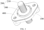
FIG. 1 is a schematic structural diagram of a battery pack connector according to some embodiments of the present disclosure. -
FIG. 2 is an exploded diagram of the structure of a battery pack connector according to some embodiments of the present disclosure. -
FIG. 3 is a schematic structural diagram of a connection portion of a battery pack connector according to some embodiments of the present disclosure. -
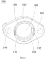
FIG. 4 is a schematic diagram of a first surface of an insulation base of a battery pack connector according to some embodiments of the present disclosure. -
FIG. 5 is a schematic diagram of a second surface of an insulation base of a battery pack connector according to some embodiments of the present disclosure. -
FIG. 6 is a schematic diagram of fitting of a battery pack connector and a box of the battery pack according to some embodiments of the present disclosure. -
FIG. 7 is a partially enlarged diagram of fitting of a battery pack connector and a box of the battery pack according to some embodiments of the present disclosure. - Description of reference signs: 100-Insulation base, 101-First surface, 102-Second surface, 110-First through hole, 111-First limiting portion, 112-Groove, 120-First boss, 130-Third boss, 131-Third limiting portion, 132-Fifth limiting portion, 140- Second through hole, 150-Fourth boss, 151-First nut, 152-Positioning hole, 200-Connection portion, 201-First end, 202-Second end, 210-Connection rod, 300-Second boss, 301-First end surface, 302-Second end surface, 310-First groove, 320-First sub-boss, 321-Fourth limiting portion, 330-Second sub-boss, 331-Second limiting portion, 400-Waterproof sealing ring, 410-Third through hole, 420-Fourth through hole, 500-Copper bar, 510-Second nut, 600-box, 610-Fifth through hole, and 620-Sixth through hole.
- As shown in
FIGS. 1 to 5 , there is provided a battery pack connector. The connector may be configured to electrically connect a battery module inside the battery pack with an electric device outside the battery pack, and include aninsulation base 100 and aconnection portion 200. The battery module of some embodiments of the present disclosure may be a module in which an end plate and a strap in the Module to Pack (MTP) are integrated with a plurality of cells, or may be a plurality of cells integrated in the Cell to Pack (CTP). - The
insulation base 100 may be provided with a first throughhole 110, and include afirst surface 101 and asecond surface 102 opposite to thefirst surface 101, where the first throughhole 110 penetrates through thefirst surface 101 and thesecond surface 102. In the present embodiments, thefirst surface 101 may be fixed to abox 600, and thesecond surface 102 may be located at a side of thefirst surface 101 away from a side wall of the box. - The
connection portion 200 may be embedded in the first throughhole 110 and fixed to theinsulation base 100, and both ends of theconnection portion 200 may extend out of theinsulation base 100. The structure of the connector is simple, and various types of connection bars inside the battery pack and various types of connection bars outside the battery pack are connected to theconnection portion 200, so that the adaptability of the connector is strong. - One of an inner side wall of the first through
hole 110 or theconnection portion 200 may be provided with a boss, and another of the inner side wall of the first throughhole 110 or theconnection portion 200 may be provided with a groove in which the boss is received, so as to keep theinsulation base 100 and theconnection portion 200 relatively fixed. - In some embodiments of the present disclosure, the inner side wall of the first through
hole 110 has afirst boss 120 disposed circumferentially along the first throughhole 110, theconnection portion 200 includes aconnection rod 210 and asecond boss 300 surrounding an outer side wall of theconnection rod 210, an outer side wall of thesecond boss 300 away from theconnection rod 210 is provided with afirst groove 310 matching thefirst boss 120, thesecond boss 300 is inserted into the first throughhole 110 and fixed to theinsulation base 100, and thefirst boss 120 is received in thefirst groove 310 to limit theconnection rod 210, so as to prevent theconnection rod 210 from coming out of the first throughhole 110. - The
connection rod 210 has opposite first andsecond ends second boss 300 has opposite first andsecond end surfaces first end 201 extends out of thefirst end surface 301, thesecond end 202 extends out of thesecond end surface 302, and thefirst end 201 extends out of thefirst surface 101 and thesecond end 202 extends out of thesecond surface 102. - The
connection rod 210 and thesecond boss 300 may be formed by connecting split-type structural members, or may be an integral structure. Theconnection rod 210 may be a double-end bolt, both ends of which are threaded to facilitate attachment of the connection rod to other connection members by means of a nut. The insulation base may be made of an insulation material such as plastic, and may be insulated from the metal box. - In the present disclosure, as shown in
FIGS. 6 to 7 , the battery pack connector is configured to be fixed to thebox 600 of the battery pack to output a current to the outside, and the connector may be directly connected to the battery module inside the battery pack or to an electric device outside the battery pack, or may be connected to the battery pack by an intermediate adapter, which is not specifically limited herein. Theinsulation base 100 of the connector may be directly fixed to thebox 600, theconnection rod 210 penetrates through the side wall of thebox 600, thesecond end 202 of theconnection rod 210 extends into thebox 600 to be connected to thecopper bar 500 inside the battery pack, and thefirst end 201 of theconnection rod 210 extends out of thebox 600 to be connected to a device outside the battery pack into which a current needs to be input, thereby realizing outputting of the current. - In one embodiment of the present disclosure, as shown in
FIGS. 4 to 5 , thefirst surface 101 is provided with athird boss 130, which is insulated and disposed continuously or intermittently around the first throughhole 110. Thethird boss 130 may be made of an insulation material such as plastic. When thefirst surface 101 is in contact with the surface of thebox 600, thethird boss 130 functions to insulate thebox 600 from theconnection portion 200. In a process of forming thefirst boss 120, a through hole may be provided first in a central portion of theinsulation base 100 and extend through thefirst surface 101 and thesecond surface 102, and then agroove 112 may be provided on thesecond surface 102 around the through hole and have an inner diameter greater than the inner diameter of the through hole to form thefirst boss 120, and then thethird boss 130 is formed on thefirst surface 101 around the through hole and have the same inner diameter as thegroove 112, and the through hole, thegroove 112, and thethird boss 130 have the same central axis (in the direction perpendicular to the insulation base 100). - In some embodiments of the present disclosure, the
third boss 130 may be integrally formed with theinsulation base 100, the inner diameter of thethird boss 130 coincides with the inner diameter of the first throughhole 110, and then thefirst boss 120 is formed in the first throughhole 110. - In some embodiments of the present disclosure, the
insulation base 100, thefirst boss 120, and thethird boss 130 may also be integrally formed by a mold. - In one embodiment of the present disclosure, as shown in
FIGS. 3 to 5 , the inner side wall of the first throughhole 110 is further provided with a first limitingportion 111, and theconnection portion 200 is further provided with a second limitingportion 331 matching the first limitingportion 111, so that thesecond boss 300 is fixed to theinsulation base 100, thereby preventing theconnection portion 200 from rotating in the circumferential direction in the first throughhole 110. Specifically, the second limitingportion 331 may be provided on the outer side wall of thesecond boss 300. The first throughhole 110 may be a circular through hole, the first limitingportion 111 may be a protrusion structure disposed on the inner side wall of the first throughhole 110, thesecond boss 300 may be a circular boss, and the second limitingportion 331 may be a recess structure disposed on the outer side wall of thesecond boss 300 and matching the shape and the size of the first limitingportion 111. When thesecond boss 300 is fitted in the first throughhole 110, the first limitingportion 111 is engaged with the second limitingportion 331, so that thesecond boss 300 is fixed to theinsulation base 100, thereby preventing theconnection portion 200 from rotating in the circumferential direction in the first throughhole 110. - In one embodiment of the present disclosure, as shown in
FIGS. 3 to 5 , the inner side wall of thethird boss 130 toward the first throughhole 110 may be provided with a third limitingportion 131, and theconnection portion 200 may be further provided with a fourth limitingportion 321 matching the third limitingportion 131. Specifically, the fourth limitingportion 321 may be provided on the outer side wall of thesecond boss 300. Thesecond boss 300 is divided by thefirst groove 310 into afirst sub-boss 320 and asecond sub-boss 330 located on both sides of thefirst groove 310, where the second limitingportion 331 is provided on thesecond sub-boss 330, and the fourth limitingportion 321 is provided on thefirst sub-boss 320. The third limitingportion 131 may be a protrusion structure disposed on the inner side wall of the first throughhole 110, and the fourth limitingportion 321 may be a recess structure disposed on the outer side wall of thesecond boss 300 and matching the protrusion structure. When thesecond boss 300 is fitted in the first throughhole 110, the second limitingportion 331 is engaged with the first limitingportion 111, and the fourth limitingportion 321 is engaged with the third limitingportion 131, so that the connection stability between theconnection portion 200 and theinsulation base 100 can be further improved, thereby preventing theconnection portion 200 from rotating in the circumferential direction in the first throughhole 110. - In one embodiment of the present disclosure, as shown in
FIGS. 2 and4 , one side of thethird boss 130 away from thefirst surface 101 is provided with a fifth limitingportion 132, and a connection bar of an external electric device is limited by the fifth limitingportion 132, so as to avoid rotation of the connection bar along the circumferential direction of theconnection rod 210 and ensure the robustness of connecting the connection bar with the connector. In the present embodiment, the fifth limitingportion 132 includes at least two protrusions extending in a direction away from thefirst surface 101. The protrusions may be perpendicular to theinsulation base 100. When theinsulation base 100 is fixed to thebox 600, the fifth limitingportion 132 is protruded from the outer surface of thebox 600, and when thethird boss 130 is provided with two protrusions, the two protrusions are arranged symmetrically with respect to the central axis of the first throughhole 110. Thefirst end 201 of theconnection rod 210 may be connected to an external wiring harness or an external device by a connection bar passing through thefirst end 201 of theconnection rod 210 and fixed between the two projections, so that the connection bar is limited by the pair of protrusions, so as to avoid rotation of the connection bar along the circumferential direction of theconnection rod 210 and ensure the robustness of connecting the connection bar with the connector. - In one embodiment of the present disclosure, as shown in
FIG. 4 , theinsulation base 100 is further provided with at least one second throughhole 140 configured to be fixed to thebox 600 by a fastener. Theinsulation base 100 may be a diamond, the first throughhole 110 may be provided at the center of theinsulation base 100, and theinsulation base 100 may be provided with two second throughholes 140 respectively located at both sides of the first throughhole 110. When theinsulation base 100 is fixed to thebox 600, a bolt may pass through thebox 600 and the second throughhole 140 to fix theinsulation base 100 to thebox 600. - In one embodiment of the present disclosure, as shown in
FIGS. 2 ,4 , and5 , a hollowfourth boss 150 is provided on thesecond surface 102. Thefourth boss 150 covers the second throughhole 140 and communicates with the second throughhole 140 to form a blind hole in which afirst nut 151 is fixed. Thefourth boss 150 may be a cylindrical groove structure and have two opposite ends in a direction perpendicular to theinsulation base 100, where one end of thefourth boss 150 close to the second throughhole 140 is an opening, and another end of thefourth boss 150 away from the second throughhole 140 is a bottom. The opening end of thefourth boss 150 communicates with the second throughhole 140, and afirst nut 151 is provided in the groove of thefourth boss 150. When theinsulation base 100 is fixed to thebox 600, thefirst surface 101 of theinsulation base 100 is attached to the surface of thebox 600. The bolt may pass through the through hole of thebox 600 to be inserted into thefirst nut 151, so that theinsulation base 100 may be fixed to thebox 600, which is simple to operate. - One end of the blind hole away from the second through
hole 140 is provided with apositioning hole 152, that is, a bottom of thefourth boss 150 is provided with a through hole penetrating through the bottom, and thepositioning hole 152 is used for a mold thimble demolding. - In one embodiment of the present disclosure, as shown in
FIG. 2 , thefirst surface 101 of theinsulation base 100 is further provided with awaterproof sealing ring 400 installed between theinsulation base 100 and thebox 600, so as to improve the waterproof level and prevent external water or liquid from being immersed in thebox 600 of the battery pack. The shape of thewaterproof sealing ring 400 may be the same as that of theinsulation base 100, and thewaterproof sealing ring 400 is provided with a third throughhole 410 corresponding to the first throughhole 110 and a fourth throughhole 420 corresponding to the second throughhole 140, so that theconnection rod 210 and the fastener pass through thewaterproof sealing ring 400. The inner diameter of the third throughhole 410 may be greater than or equal to the outer diameter of thethird boss 130, and the thickness of thewaterproof sealing ring 400 may coincide with the thickness of thethird boss 130 in the direction perpendicular to theinsulation base 100. Thewaterproof sealing ring 400 may be sleeved on the periphery of thethird boss 130, and thethird boss 130 can limit the position of thewaterproof sealing ring 400, thereby avoiding displacement of thewaterproof sealing ring 400 in the direction parallel to theinsulation base 100. - The present disclosure may further provide a battery pack, including: a
box 600, a battery module located in thebox 600, and the battery pack connector as described above, where the connector is fixed to thebox 600 of the battery pack. - As shown in
FIGS. 6 to 7 , the connector may be fitted onto a side wall of thebox 600 where a fifth throughhole 610 corresponding to the first throughhole 110 and a sixth throughhole 620 corresponding to the second throughhole 140 are provided. The connector may be fitted onto an inner side of thebox 600, where thefirst surface 101 of theinsulation base 100 is attached to the inner side wall of thebox 600, the first throughhole 110 corresponds to the fifth throughhole 610, thefirst end 201 of theconnection rod 210 passes through the fifth throughhole 610 to be connected to an external wiring harness or an external device, thesecond end 202 of theconnection rod 210 is located in thebox 600 to be connected to acopper bar 500 of the battery module, and thesecond end 202 of theconnection rod 210 passes through a hole reserved in thecopper bar 500 and is bolted by asecond nut 510. The second throughhole 140 corresponds to the sixth throughhole 620, and the bolt sequentially passes through the sixth throughhole 620 and the second throughhole 140 is bolted by afirst nut 151, so that the connector is fixed to thebox 600 and connected to thecopper bar 500 of thebox 600, thereby outputting the current of the battery pack to the outside of the battery pack. - The
waterproof sealing ring 400 may be further provided between thefirst surface 101 of theinsulation base 100 and the inner side wall of thebox 600, so as to prevent the external water or liquid from being immersed in thebox 600 of the battery pack and meeting IP67 protection level. - In some embodiments of the present disclosure, the material of the
box 600 may be a metal or a plastic, which is not specifically limited herein. The battery pack may be a low-voltage battery pack or a high-voltage battery pack. The battery pack connector may be preferably applied to the low-voltage battery pack, but may also be applied to the high-voltage battery pack.
Claims (15)
- A battery pack connector for electrically connecting a battery module inside a battery pack with an electric device outside the battery pack, characterized in that the battery pack connector comprises: an insulation base (100) and a connection portion (200);the insulation base (100) is provided with a first through hole (110) and comprises a first surface (101) and a second surface (102) opposite to the first surface (101), wherein the first through hole (110) penetrates through the first surface (101) and the second surface (102); andthe connection portion (200) is embedded in the first through hole (110) and fixed to the insulation base (100), and both ends of the connection portion (200) extend out of the insulation base (100).
- The battery pack connector of claim 1, characterized in that one of an inner side wall of the first through hole (110) or the connection portion (200) is provided with a boss, and another of the inner side wall of the first through hole (110) or the connection portion (200) is provided with a groove in which the boss is received.
- The battery pack connector of claim 2, characterized in that the inner side wall of the first through hole (110) has a first boss (120) disposed circumferentially along the first through hole (110); and
the connection portion (200) comprises a connection rod (210) and a second boss (300) surrounding an outer side wall of the connection rod (210), an outer side wall of the second boss (300) away from the connection rod (210) is provided with a first groove (310) matching the first boss (120), and the second boss (300) is inserted into the first through hole (110). - The battery pack connector of claim 1, characterized in that the first surface (101) is provided with a third boss (130) that is insulated and disposed continuously or intermittently around the first through hole (110).
- The battery pack connector of claim 1, characterized in that the inner side wall of the first through hole (110) is further provided with a first limiting portion (111), and the connection portion (200) is further provided with a second limiting portion (331) matching the first limiting portion (111).
- The battery pack connector of claim 5, characterized in that the first limiting portion (111) is a protrusion structure disposed on the inner side wall of the first through hole (110), and the second limiting portion (331) is a recess structure disposed on the outer side wall of the second boss (300) and matching the protrusion structure.
- The battery pack connector of claim 4, characterized in that the inner side wall of the third boss (130) toward the first through hole (110) is provided with a third limiting portion (131), and the connection portion (200) is further provided with a fourth limiting portion (321) matching the third limiting portion (131).
- The battery pack connector of claim 4, characterized in that one side of the third boss (130) away from the first surface (101) is provided with a fifth limiting portion (132).
- The battery pack connector of claim 8, characterized in that the fifth limiting portion (132) comprises at least two protrusions extending in a direction away from the first surface (101).
- The battery pack connector of any one of claims 1-9, characterized in that the insulation base (100) is further provided with at least one second through hole (140), the second surface (102) is provided with a hollow fourth boss (150), and the fourth boss (150) covers the second through hole (140) and communicates with the second through hole (140) to form a blind hole in which a first nut (151) is fixed.
- The battery pack connector of claim 10, characterized in that one end of the blind hole away from the second through hole (140) is provided with a positioning hole (152).
- The battery pack connector of any one of claims 1-9, characterized in that the first surface (101) of the insulation base (100) is further provided with a waterproof sealing ring (400).
- The battery pack connector of any one of claims 1-9, characterized in that the insulation base (100) is a diamond.
- The battery pack connector of any one of claims 1-9, characterized in that the connection portion (200) is a double-end bolt.
- A battery pack, characterized in that the battery pack comprises: a box (600), a battery module located in the box (600), and the battery pack connector of any one of claims 1-14, wherein the battery pack connector is fixed to the box (600) of the battery pack.
Applications Claiming Priority (2)
| Application Number | Priority Date | Filing Date | Title |
|---|---|---|---|
| CN202323669292.1U CN222126869U (en) | 2023-12-29 | 2023-12-29 | Battery pack connecting piece and battery pack |
| PCT/CN2024/109005 WO2025138797A1 (en) | 2023-12-29 | 2024-07-31 | Battery pack connector and battery pack |
Publications (1)
| Publication Number | Publication Date |
|---|---|
| EP4579934A1 true EP4579934A1 (en) | 2025-07-02 |
Family
ID=93100384
Family Applications (1)
| Application Number | Title | Priority Date | Filing Date |
|---|---|---|---|
| EP24205906.1A Pending EP4579934A1 (en) | 2023-12-29 | 2024-10-10 | Battery pack connector and battery pack |
Country Status (2)
| Country | Link |
|---|---|
| US (1) | US20250219259A1 (en) |
| EP (1) | EP4579934A1 (en) |
Citations (2)
| Publication number | Priority date | Publication date | Assignee | Title |
|---|---|---|---|---|
| JP2012094372A (en) * | 2010-10-27 | 2012-05-17 | Miyagawa Kasei Ind Co Ltd | Lid of storage battery, housing of storage battery, and storage battery |
| US20220367954A1 (en) * | 2019-11-29 | 2022-11-17 | Lg Energy Solution, Ltd. | Battery Pack, Electronic Device and Vehicle |
-
2024
- 2024-10-10 EP EP24205906.1A patent/EP4579934A1/en active Pending
- 2024-12-24 US US19/000,784 patent/US20250219259A1/en active Pending
Patent Citations (2)
| Publication number | Priority date | Publication date | Assignee | Title |
|---|---|---|---|---|
| JP2012094372A (en) * | 2010-10-27 | 2012-05-17 | Miyagawa Kasei Ind Co Ltd | Lid of storage battery, housing of storage battery, and storage battery |
| US20220367954A1 (en) * | 2019-11-29 | 2022-11-17 | Lg Energy Solution, Ltd. | Battery Pack, Electronic Device and Vehicle |
Also Published As
| Publication number | Publication date |
|---|---|
| US20250219259A1 (en) | 2025-07-03 |
Similar Documents
| Publication | Publication Date | Title |
|---|---|---|
| US8383939B2 (en) | Structure of bus bar assembly | |
| US20230122520A1 (en) | Top cover assembly and battery | |
| CN109546018B (en) | Battery top cover and power battery using same | |
| CN100407506C (en) | Housing element with joint part | |
| CN115051089A (en) | Split type battery top cover assembly | |
| CN218274683U (en) | Single battery and battery pack | |
| US5449570A (en) | Connection arrangement for battery monitoring circuits | |
| CN115051088A (en) | Pole riveting assembly method and structure and integrated battery top cover assembly | |
| CN214477582U (en) | Fuel cell system and vehicle | |
| JP2013143395A (en) | Power storage module | |
| EP4579934A1 (en) | Battery pack connector and battery pack | |
| CN117254176A (en) | Cover plate of cylindrical battery and cylindrical battery | |
| CN207781725U (en) | Connecting terminal and battery pack for battery pack | |
| CN212435595U (en) | An inverter junction box | |
| CN210576721U (en) | Waterproof, shielding and insulating integrated switching hole cover assembly | |
| CN221486721U (en) | Battery Pack | |
| CN219575770U (en) | Battery cover plate assembly capable of being assembled rapidly | |
| CN222126869U (en) | Battery pack connecting piece and battery pack | |
| CN207753229U (en) | A kind of metal locking type connector | |
| CN114497609B (en) | A casing and fuel cell | |
| KR101263834B1 (en) | Junction box for a photovoltaic module | |
| CN210137237U (en) | Stator shell and range extender of generator | |
| CN221102246U (en) | Cover plate of cylindrical battery and cylindrical battery | |
| CN222395091U (en) | Connectors and Vehicles | |
| CN218300094U (en) | Battery waterproof case and battery module |
Legal Events
| Date | Code | Title | Description |
|---|---|---|---|
| PUAI | Public reference made under article 153(3) epc to a published international application that has entered the european phase |
Free format text: ORIGINAL CODE: 0009012 |
|
| STAA | Information on the status of an ep patent application or granted ep patent |
Free format text: STATUS: REQUEST FOR EXAMINATION WAS MADE |
|
| 17P | Request for examination filed |
Effective date: 20241010 |
|
| AK | Designated contracting states |
Kind code of ref document: A1 Designated state(s): AL AT BE BG CH CY CZ DE DK EE ES FI FR GB GR HR HU IE IS IT LI LT LU LV MC ME MK MT NL NO PL PT RO RS SE SI SK SM TR |