EP4579929A1 - Battery cell, battery, and electrical device - Google Patents
Battery cell, battery, and electrical device Download PDFInfo
- Publication number
- EP4579929A1 EP4579929A1 EP22963313.6A EP22963313A EP4579929A1 EP 4579929 A1 EP4579929 A1 EP 4579929A1 EP 22963313 A EP22963313 A EP 22963313A EP 4579929 A1 EP4579929 A1 EP 4579929A1
- Authority
- EP
- European Patent Office
- Prior art keywords
- tab
- end cover
- battery cell
- adapter
- bracket
- Prior art date
- Legal status (The legal status is an assumption and is not a legal conclusion. Google has not performed a legal analysis and makes no representation as to the accuracy of the status listed.)
- Pending
Links
Images


Classifications
-
- H—ELECTRICITY
- H01—ELECTRIC ELEMENTS
- H01M—PROCESSES OR MEANS, e.g. BATTERIES, FOR THE DIRECT CONVERSION OF CHEMICAL ENERGY INTO ELECTRICAL ENERGY
- H01M50/00—Constructional details or processes of manufacture of the non-active parts of electrochemical cells other than fuel cells, e.g. hybrid cells
- H01M50/50—Current conducting connections for cells or batteries
- H01M50/528—Fixed electrical connections, i.e. not intended for disconnection
-
- H—ELECTRICITY
- H01—ELECTRIC ELEMENTS
- H01M—PROCESSES OR MEANS, e.g. BATTERIES, FOR THE DIRECT CONVERSION OF CHEMICAL ENERGY INTO ELECTRICAL ENERGY
- H01M50/00—Constructional details or processes of manufacture of the non-active parts of electrochemical cells other than fuel cells, e.g. hybrid cells
- H01M50/50—Current conducting connections for cells or batteries
- H01M50/531—Electrode connections inside a battery casing
- H01M50/536—Electrode connections inside a battery casing characterised by the method of fixing the leads to the electrodes, e.g. by welding
-
- H—ELECTRICITY
- H01—ELECTRIC ELEMENTS
- H01M—PROCESSES OR MEANS, e.g. BATTERIES, FOR THE DIRECT CONVERSION OF CHEMICAL ENERGY INTO ELECTRICAL ENERGY
- H01M50/00—Constructional details or processes of manufacture of the non-active parts of electrochemical cells other than fuel cells, e.g. hybrid cells
- H01M50/50—Current conducting connections for cells or batteries
- H01M50/543—Terminals
- H01M50/564—Terminals characterised by their manufacturing process
- H01M50/566—Terminals characterised by their manufacturing process by welding, soldering or brazing
-
- Y—GENERAL TAGGING OF NEW TECHNOLOGICAL DEVELOPMENTS; GENERAL TAGGING OF CROSS-SECTIONAL TECHNOLOGIES SPANNING OVER SEVERAL SECTIONS OF THE IPC; TECHNICAL SUBJECTS COVERED BY FORMER USPC CROSS-REFERENCE ART COLLECTIONS [XRACs] AND DIGESTS
- Y02—TECHNOLOGIES OR APPLICATIONS FOR MITIGATION OR ADAPTATION AGAINST CLIMATE CHANGE
- Y02E—REDUCTION OF GREENHOUSE GAS [GHG] EMISSIONS, RELATED TO ENERGY GENERATION, TRANSMISSION OR DISTRIBUTION
- Y02E60/00—Enabling technologies; Technologies with a potential or indirect contribution to GHG emissions mitigation
- Y02E60/10—Energy storage using batteries
Definitions
- This application relates to the field of battery technologies, and in particular, to a battery cell, a battery, and an electric device.
- a secondary battery includes positive and negative electrode plates with tabs.
- tabs are typically bent, and the bent portions of the tabs are clamped by the tab bracket, so as to facilitate the shaping of the tabs or to support the tabs.
- the position of the tab bracket inside the battery is unstable and prone to displacement, which affects the effect of shaping or supporting the bent portions of the tabs, thus compromising the safety performance and cycle life of the battery.
- a battery cell includes a housing, an end cover assembly, an electrode assembly, a tab bracket, and a fixing member, where the end cover assembly closes an opening of the housing, the tab bracket is provided on a side of the electrode assembly facing the end cover assembly, the tab is bent around the tab bracket, and the fixing member is configured to fix the tab bracket to the end cover assembly.
- the tab bracket is fixed to the end cover assembly of the battery cell.
- the fixing effect provided by the end cover assembly pulling on the tab bracket allows the tab bracket to remain stable in the initial assembly position when the battery is inverted or the battery is subjected to stress. This prevents loosening or displacement of the tab bracket inside the battery, and allows the tab bracket to play the role of shaping and supporting the tab, thus improving the safety performance and cycle life of the battery.
- the end cover assembly includes an end cover and an adapter member, where the end cover has an electrode terminal electrically connected to the tab, the adapter member is provided between the end cover and the tab bracket and configured to electrically interconnect the electrode terminal and the tab, and the fixing member is configured to fix the tab bracket to the end cover.
- the adapter member improves the safety of the battery cell.
- the tab bracket is fixed to the adapter member via the fixing member, avoiding problems such as deformation of the tab caused by displacement of the tab bracket, as well as the resulting impact on the electrical connection between the tab and the electrode terminal.
- the fixing member is layered between the tab bracket and the adapter member, to prevent the arrangement of the fixing member from taking up space in other directions inside the battery cell. It is only necessary to consider increasing the thickness in the direction where the tab bracket and the adapter member are layered, achieving high space utilization and compact structure inside the battery cell.
- the adapter member includes a first adapter portion and a second adapter portion electrically connected to each other, where the first adapter portion is configured to be electrically connected to the electrode terminal, the second adapter is configured to be electrically connected to the tab, and the fixing member is provided between the first adapter portion and the tab bracket or between the second adapter portion and the tab bracket.
- the adapter member includes a first adapter portion and a second adapter portion electrically connected to each other, where the first adapter portion is configured to be electrically connected to the electrode terminal, the second adapter is configured to be electrically connected to the tab, and the fixing member is provided between the first adapter portion and the tab bracket and between the second adapter portion and the tab bracket.
- the fixing member can be arranged more flexibly according to the adapter structure of the adapter member, ensuring the interconnecting function of the adapter member while fixing the tab bracket to the adapter member.
- the fixing member is an adhesive layer.
- the tab bracket can be adhered to the end cover assembly, improving the stability of the tab bracket.
- the adhesive layer is a non-metallic member, and will not cause short circuit or the like with other electrical components, making the battery cell much safer.
- the adapter member is welded to the electrode terminal, and an orthographic projection of the fixing member on the adapter member covers a welding position between the adapter member and the electrode terminal.
- the side of the adapter member away from the tab bracket is welded to the electrode terminal, so that after metal particles are generated by the welding of the tab bracket and the motor terminal, the metal particles falling toward the interior of the battery first pass through the fixing member, and thus will be intercepted by the adhesive layer formed by the fixing member, preventing the metal particles from further falling into the battery.
- the tab bracket is provided with an accommodating hole, and at least a portion of the adhesive layer is located within the accommodating hole.
- the thickness in the direction where the tab bracket and the adapter member are layered is reduced, thus reducing the internal space occupation of the battery cell, achieving high space utilization of the battery cell, and improving the wetting effect on the electrode plate.
- an opening area of the accommodating hole is denoted as A
- area of the weld mark produced at the welding position between the adapter member and the electrode terminal is denoted as B
- a ratio of A to B ranges from 1/2 to 2/3.
- the adhesive layer provided inside the accommodating hole partially overflows to outside the accommodating hole and connects to one side surface of the tab bracket. This guarantees fixation of the tab bracket and improves the wetting effect of the electrode plate without occupying too much internal space of the battery cell, thus ensuring sufficient space for the electrode assembly and electrolyte inside the housing to avoid reducing the energy density of the battery cell.
- the end cover assembly includes an end cover, where the end cover has an electrode terminal electrically connected to the tab, and the fixing member is configured to fix the tab bracket to the end cover of the end cover assembly.
- Fixing the tab bracket to the end cover ensures the stability of the electrical connection between the tab and the electrode terminal. Additionally, such arrangement ensures fixation of the tab bracket through the end cover, avoiding problems such as deformation of the tab caused by displacement of the tab bracket, as well as the resulting impact on the electrical connection between the tab and the electrode terminal.
- the end cover assembly includes an end cover and an insulating member, where the end cover is provided with an electrode terminal, the insulating member is provided between the end cover and the tab, and the fixing member is configured to fix the tab bracket to the insulating member.
- the fixing member is connected to the insulating member so as to realize its connection with the end cover. This can avoid problems such as deformation of the tab caused by displacement of the tab bracket, thus preventing the further impact on the electrical connection between the tab and the electrode terminal. Additionally, such arrangement can prevent the end cover with the electrode terminal provided thereon from being directly connected to the tab bracket, thus reducing the risk of the fixing member interfering with the electrode terminal.
- the fixing member is an adhesive layer.
- thickness of the adhesive layer ranges from 0.05 mm to 7 mm. When the thickness of the adhesive layer is less than 0.05 mm, the adhesive layer is too thin with too little adhesive, resulting in a weak connection and fixation of the tab bracket. When the thickness of the adhesive layer is greater than 7 mm, the adhesive layer is too thick, occupying too much internal space of the battery cell, which not only affects the arrangement of the electrode assembly, but also may affect the normal bending of the tab.
- a battery including the battery cell in the foregoing embodiments.
- an electric device including the battery according to any one of the foregoing embodiments, where the battery is configured to supply electric energy.
- the end cover assembly 21 and the housing 24 may form a shared connection surface before other components are disposed in the housing and then, the end cover assembly 21 covers the housing 24 when inside of the housing 24 needs to be enclosed.
- the housing 24 may be of various shapes and sizes, such as a cuboid shape, a cylindrical shape, and a hexagonal prism shape. Specifically, a shape of the housing 24 may be determined according to a specific shape and size of the electrode assembly 25.
- the housing 24 may be made of various materials, such as copper, iron, aluminum, stainless steel, aluminum alloy, and plastic, which are not particularly limited in the embodiments of this application.
- this application provides a battery cell 20 including an end cover assembly 21, a tab bracket 22, a fixing member 23, a housing 24, and an electrode assembly 25.
- the housing 24 has an opening.
- the end cover assembly 21 closes the opening of the housing 24.
- the electrode assembly 25 is provided in the housing 24 and provided with a tab 251.
- the tab bracket 22 is provided on a side of the end cover assembly 21 facing the electrode assembly 25, where the tab 251 is bent around the tab bracket 22.
- the fixing member 23 is configured to fix the tab bracket 22 to the end cover assembly 21.
- the end cover assembly 21 refers to a component that covers an opening of the housing 24 to isolate an internal environment of the battery cell 20 from an external environment. For its specific arrangement method and shape, refer to the above description.
- the end cover assembly 21 may be an integral structure, or it may be formed by combining multiple layers, and the multi-layer structure forming the end cover assembly 21 may have a variety of different functions.
- the tabs 251 formed by the portions of the anode electrode plate and the cathode electrode plate without active substances, to reduce the installation space inside the battery cell 20 and facilitate the assembling of the battery cell 20, the tabs 251 are typically bent, but the bent tabs 251 may be unstable inside the battery cell 20.
- the tab bracket 22 is disposed inside the battery cell 20 for fixing the bent tabs 251, that is, the tabs 251 are bent around the tab bracket 22, and the bent tabs 251 are supported by the tab bracket 22 for facilitating the shaping of the tabs 251 or for supporting the tabs 251.
- a sheet-like tab 251 is formed after the winding of the electrode assembly 25 is completed.
- the tab 251 needs to be bent.
- the tab bracket 22 can be placed on one side of the tab 251, so that a portion of the tab 251 is bent around the tab bracket 22 and lapped above the tab bracket 22, a bent tab space is formed within the bent tab 251, and the tab bracket 22 is disposed within the bent tab space to support the bent tab 251.
- the bent tab space may be formed with the aid of an external device, and then the tab bracket 22 is placed inside the bent tab space to support the bent tab 251.
- the tab bracket 22 may be plate-like, block-like, or other structures, and its specific size and shape need to be set according to the bending degree of the tab 251 and the installation space of the bent tab 251, and are not limited in this application.
- At least a portion of the electrode terminal 27 is exposed outside the battery cell 20 to facilitate connection to other members (such as a busbar), so as to lead out electric energy generated by the electrode assembly 25 of the battery cell 20 through the tab 251 and the electrode terminal 27.
- the electrode terminal 27 may be a part of the end cover 211 or a separate member mounted on the end cover 211.
- the electrode terminal 27 and the tab 251 are connected using an adapter member 212, instead of connected directly. This not only avoids the situation where the adapter member 212 is fused during short circuit, overcharging, or overdischarging of the electrode assembly 25 and thus interrupts the current transmission between the electrode terminal 27 and the tab 251, but also prevents damage to the battery 100 or burning of other components during short circuit, overcharging, or overdischarging of the electrode assembly 25, thus ensuring the use safety of the battery 100.
- the adapter member 212 may be an adapter sheet or an overcurrent protection sheet, or an aggregate of the adapter sheet and the overcurrent protection sheet, which is not limited in this application.
- the tab bracket 22 and the adapter member 212 are connected through the fixing member 23.
- the fixing member 23 may be layered between the tab bracket 22 and the adapter member 212, or clamp or snap-fit the tab bracket 22 and the adapter member 212 together using an additional structure.
- the specific fixing shape of the fixing member 23 is not limited, and needs to match the actual shape of the adapter member 212. After the electrical connection of the adapter member 212 with the electrode assembly 25 and the tab 251 is ensured, fixing with the tab bracket 22 is achieved by utilizing other regions of the adapter member 212.
- the tab bracket 22 is fixed to the adapter member 212 through the fixing member 23, avoiding problems such as deformation of the tab 251 caused by displacement of the tab bracket 22 from affecting the electrical connection between the tab 251 and the electrode terminal 27.
- the two sides of the fixing member 23, which are back to back, are fixedly connected to the tab bracket 22 and the adapter member 212, respectively, so as to fixedly connect the tab bracket 22 and the adapter member 212.
- the fixing member 23 may be of an integral structure, or it may be formed by a plurality of modules spliced together, so as to connect the tab bracket 22 and the adapter member 212.
- the adapter member 212 includes a first adapter portion 212a and a second adapter portion 212b electrically connected to each other, where the first adapter portion 212a is configured to be electrically connected to the electrode terminal 27, the second adapter is configured to be electrically connected to the tab 251, and the fixing member 23 is provided between the first adapter portion 212a and the tab bracket 22 and/or between the second adapter portion 212b and the tab bracket 22.
- connection method of the first adapter portion 212a and the second adapter portion 212b is not limited.
- an intermediate piece for electrical interconnection is provided between the first adapter portion 212a and the second adapter portion 212b, or the first adapter portion 212a is directly connected to the second adapter portion 212b.
- the shapes of the first adapter portion 212a and the second adapter portion 212b is not limited.
- a side of the first adapter portion 212a facing the electrode terminal 27 is connected to the electrode terminal 27, and a side of the second adapter portion 212b facing the tab 251 is connected to the bent tab 251, thus implementing the electrical interconnection function.
- the adapter member 212 needs to be made of a conductive metal member to achieve its electrical interconnection function.
- the fixing member 23 can be arranged more flexibly according to the adapter structure of the adapter member 212, ensuring the interconnecting function of the adapter member 212 while stably fixing the tab bracket 22 to the adapter member 212.
- the tab bracket 22 can be adhered to the end cover assembly 21, improving the stability of the tab bracket 22.
- the adhesive layer is a non-metallic member, and will not cause short circuit or the like with other electrical components, making the battery cell 20 much safer.
- the orthographic projection of the fixing member 23 on the adapter member 212 covers the welding position 212c of the adapter member 212 and the electrode terminal 27, so that any welding residue, such as metal particles, generated at the welding position 212c will first pass through the fixing member 23 before falling into the interior of the battery cell 20.
- the tab bracket 22 is provided with an accommodating hole 22a, and at least a portion of the adhesive layer is located within the accommodating hole 22a.
- the accommodating hole 22a may extend through the tab bracket 22, or may not extend through the tab bracket 22.
- An adhesive material is placed into the accommodating hole 22a through coating, dispensing, heat sealing, or the like, and the adhesive layer formed after drying of the adhesive material is adhered to the hole wall of the accommodating hole 22a or the surface of the tab bracket 22 provided with the accommodating hole 22a, and also to the adapter member 212 provided on its upper layer.
- the accommodating hole 22a provided in this application can appropriately increase the body volume (that is, the accommodating hole 22a on the tab bracket 22) for fixing the adhesive layer, and the adhesive layer is partially located inside the tab bracket 22. This reduces the thickness in the direction where the tab bracket 22 and the adapter member 212 are layered, thus reducing the internal space occupation of the battery cell 20, achieving high space utilization of the battery cell 20, and improving the wetting effect on the electrode plate.
- each accommodating hole 22a can be adjusted according to requirements, and each accommodating hole 22a is provided with an adhesive layer, which allows for more even force distribution on the tab bracket 22 and improves the fixation effect.
- the area A of the accommodating hole 22a is smaller than the area B of the weld mark, and the area of the adhesive layer disposed in the accommodating hole 22a is larger than the weld mark area.
- the adhesive layer disposed inside the accommodating hole 22a partially overflows to outside the accommodating hole 22a and connects to one side surface of the tab bracket 22. This guarantees fixation of the tab bracket 22 and improves the wetting effect of the electrode plate without occupying too much internal space of the battery cell 20, thus ensuring sufficient space for the electrode assembly 25 and electrolyte inside the housing 24 to avoid reducing the energy density of the battery cell 20.
- the end cover assembly 21 includes an end cover 211, where the end cover 211 has an electrode terminal 27 electrically connected to the tab 251, and the fixing member 23 is configured to fix the tab bracket 22 to the end cover 211 of the end cover assembly 21.
- At least a portion of the electrode terminal 27 is exposed outside the battery cell 20 to facilitate connection to other members (such as a busbar), so as to lead out electric energy generated by the electrode assembly 25 of the battery cell 20 through the tab 251 and the electrode terminal 27.
- the electrode terminal 27 may be a part of the end cover 211 or a separate member mounted on the end cover 211.
Landscapes
- Chemical & Material Sciences (AREA)
- Chemical Kinetics & Catalysis (AREA)
- Electrochemistry (AREA)
- General Chemical & Material Sciences (AREA)
- Engineering & Computer Science (AREA)
- Manufacturing & Machinery (AREA)
- Connection Of Batteries Or Terminals (AREA)
Abstract
Description
- This application claims priority to
Chinese Patent Application No. 2022228352020, filed on October 27, 2022 - This application relates to the field of battery technologies, and in particular, to a battery cell, a battery, and an electric device.
- Energy saving and emission reduction are crucial to the sustainable development of the automobile industry. Electric vehicles, with their advantages in energy conservation and emission reduction, have become an important part of sustainable development of the automobile industry. For electric vehicles, battery technology is an important factor in connection with their development.
- A secondary battery includes positive and negative electrode plates with tabs. In the manufacturing process, to save installation space inside the secondary battery and facilitate the assembling of the secondary battery, tabs are typically bent, and the bent portions of the tabs are clamped by the tab bracket, so as to facilitate the shaping of the tabs or to support the tabs.
- However, the position of the tab bracket inside the battery is unstable and prone to displacement, which affects the effect of shaping or supporting the bent portions of the tabs, thus compromising the safety performance and cycle life of the battery.
- In view of this, it is necessary to provide a battery cell, a battery, and an electric device that can effectively improve the stability of the tab bracket and prevent loosening or displacement of the tab bracket inside the battery, in response to the problem of the unstable position of the tab bracket inside the battery.
- A battery cell includes a housing, an end cover assembly, an electrode assembly, a tab bracket, and a fixing member, where the end cover assembly closes an opening of the housing, the tab bracket is provided on a side of the electrode assembly facing the end cover assembly, the tab is bent around the tab bracket, and the fixing member is configured to fix the tab bracket to the end cover assembly.
- With such arrangement, in the battery cell provided in this application, the tab bracket is fixed to the end cover assembly of the battery cell. The fixing effect provided by the end cover assembly pulling on the tab bracket allows the tab bracket to remain stable in the initial assembly position when the battery is inverted or the battery is subjected to stress. This prevents loosening or displacement of the tab bracket inside the battery, and allows the tab bracket to play the role of shaping and supporting the tab, thus improving the safety performance and cycle life of the battery.
- In some embodiments, the end cover assembly includes an end cover and an adapter member, where the end cover has an electrode terminal electrically connected to the tab, the adapter member is provided between the end cover and the tab bracket and configured to electrically interconnect the electrode terminal and the tab, and the fixing member is configured to fix the tab bracket to the end cover.
- Arrangement of the adapter member improves the safety of the battery cell. Moreover, the tab bracket is fixed to the adapter member via the fixing member, avoiding problems such as deformation of the tab caused by displacement of the tab bracket, as well as the resulting impact on the electrical connection between the tab and the electrode terminal.
- In some embodiments, the fixing member is layered between the tab bracket and the adapter member, to prevent the arrangement of the fixing member from taking up space in other directions inside the battery cell. It is only necessary to consider increasing the thickness in the direction where the tab bracket and the adapter member are layered, achieving high space utilization and compact structure inside the battery cell.
- In some embodiments, the adapter member includes a first adapter portion and a second adapter portion electrically connected to each other, where the first adapter portion is configured to be electrically connected to the electrode terminal, the second adapter is configured to be electrically connected to the tab, and the fixing member is provided between the first adapter portion and the tab bracket or between the second adapter portion and the tab bracket.
- In some embodiments, the adapter member includes a first adapter portion and a second adapter portion electrically connected to each other, where the first adapter portion is configured to be electrically connected to the electrode terminal, the second adapter is configured to be electrically connected to the tab, and the fixing member is provided between the first adapter portion and the tab bracket and between the second adapter portion and the tab bracket.
- In this way, the fixing member can be arranged more flexibly according to the adapter structure of the adapter member, ensuring the interconnecting function of the adapter member while fixing the tab bracket to the adapter member.
- In some embodiments, the fixing member is an adhesive layer. With the adhesive layer provided, the tab bracket can be adhered to the end cover assembly, improving the stability of the tab bracket. Moreover, the adhesive layer is a non-metallic member, and will not cause short circuit or the like with other electrical components, making the battery cell much safer.
- In some embodiments, the adapter member is welded to the electrode terminal, and an orthographic projection of the fixing member on the adapter member covers a welding position between the adapter member and the electrode terminal.
- With the fixing member provided between the tab bracket and the adapter member, the side of the adapter member away from the tab bracket is welded to the electrode terminal, so that after metal particles are generated by the welding of the tab bracket and the motor terminal, the metal particles falling toward the interior of the battery first pass through the fixing member, and thus will be intercepted by the adhesive layer formed by the fixing member, preventing the metal particles from further falling into the battery.
- In some embodiments, the tab bracket is provided with an accommodating hole, and at least a portion of the adhesive layer is located within the accommodating hole.
- With the adhesive layer partially located inside the tab bracket, the thickness in the direction where the tab bracket and the adapter member are layered is reduced, thus reducing the internal space occupation of the battery cell, achieving high space utilization of the battery cell, and improving the wetting effect on the electrode plate.
- In some embodiments, an opening area of the accommodating hole is denoted as A, area of the weld mark produced at the welding position between the adapter member and the electrode terminal is denoted as B, and a ratio of A to B ranges from 1/2 to 2/3. In this case, the adhesive layer provided inside the accommodating hole partially overflows to outside the accommodating hole and connects to one side surface of the tab bracket. This guarantees fixation of the tab bracket and improves the wetting effect of the electrode plate without occupying too much internal space of the battery cell, thus ensuring sufficient space for the electrode assembly and electrolyte inside the housing to avoid reducing the energy density of the battery cell.
- In some embodiments, the end cover assembly includes an end cover, where the end cover has an electrode terminal electrically connected to the tab, and the fixing member is configured to fix the tab bracket to the end cover of the end cover assembly.
- Fixing the tab bracket to the end cover ensures the stability of the electrical connection between the tab and the electrode terminal. Additionally, such arrangement ensures fixation of the tab bracket through the end cover, avoiding problems such as deformation of the tab caused by displacement of the tab bracket, as well as the resulting impact on the electrical connection between the tab and the electrode terminal.
- In some embodiments, the end cover assembly includes an end cover and an insulating member, where the end cover is provided with an electrode terminal, the insulating member is provided between the end cover and the tab, and the fixing member is configured to fix the tab bracket to the insulating member. The fixing member is connected to the insulating member so as to realize its connection with the end cover. This can avoid problems such as deformation of the tab caused by displacement of the tab bracket, thus preventing the further impact on the electrical connection between the tab and the electrode terminal. Additionally, such arrangement can prevent the end cover with the electrode terminal provided thereon from being directly connected to the tab bracket, thus reducing the risk of the fixing member interfering with the electrode terminal.
- In some embodiments, the fixing member is an adhesive layer.
In some embodiments, thickness of the adhesive layer ranges from 0.05 mm to 7 mm. When the thickness of the adhesive layer is less than 0.05 mm, the adhesive layer is too thin with too little adhesive, resulting in a weak connection and fixation of the tab bracket. When the thickness of the adhesive layer is greater than 7 mm, the adhesive layer is too thick, occupying too much internal space of the battery cell, which not only affects the arrangement of the electrode assembly, but also may affect the normal bending of the tab. - According to a second aspect of this application, a battery is provided, including the battery cell in the foregoing embodiments.
- According to a third aspect of this application, an electric device is provided, including the battery according to any one of the foregoing embodiments, where the battery is configured to supply electric energy.
- Details of one or more embodiments of this application are presented in the accompanying drawings and description below. Other features, purposes, and advantages of this application will become apparent from the specification, the accompanying drawings, and the claims.
- To describe the technical solutions in the embodiments of this application or in the conventional art more clearly, the following briefly describes the accompanying drawings required for describing the embodiments or conventional art. Apparently, the accompanying drawings in the following description show merely embodiments of this application, and persons of ordinary skill in the art may still derive other drawings from the disclosed accompanying drawings without creative efforts.
-
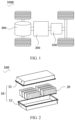
FIG. 1 is a schematic structural diagram of a vehicle according to some embodiments of this application; -
FIG. 2 is an exploded view of a structure of a battery according to some embodiments of this application; -
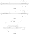
FIG. 3 is a structural exploded view of a battery cell according to some embodiments of this application; -
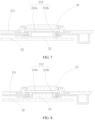
FIG. 4 is a schematic cross-sectional view of an end cover assembly according to some embodiments of this application; -
FIG. 5 is a schematic cross-sectional view of an end cover assembly according to some embodiments of this application; -
FIG. 6 is a partially enlarged schematic view of the end cover assembly provided inFIG. 4 ; -
FIG. 7 is a partially enlarged schematic view of the end cover assembly provided inFIG. 5 ; -
FIG. 8 is a first schematic partial cross-sectional view of an end cover assembly according to some embodiments of this application; and -
FIG. 9 is a second schematic partial cross-sectional view of an end cover assembly according to some embodiments of this application.
1000. vehicle; 100. battery; 200. controller; 300. motor; 10. box; 11. first portion; 12. second portion; 20. battery cell; 21. end cover assembly; 211. end cover; 211a. injection hole; 212. adapter member; 212a. first adapter portion; 212b. second adapter portion; 212c. welding position; 22. tab bracket; 22a. accommodating hole; 23. fixing member; 24. housing; 25. electrode assembly; 251. tab; 26. pressure relief mechanism; and 27. electrode terminal. - The following clearly and completely describes the technical solutions in the embodiments of this application with reference to the accompanying drawings in the embodiments of this application. Apparently, the described embodiments are merely some but not all embodiments of this application. All other embodiments obtained by a person of ordinary skill in the art based on the embodiments of this application without creative efforts shall fall within the protection scope of this application.
- Currently, from a perspective of the market development, application of traction batteries is being more extensive. Traction batteries have been not only used in energy storage power supply systems such as hydroelectric power plants, thermal power plants, wind power plants, and solar power plants, but also widely used in many other fields including electric transportation tools such as electric bicycles, electric motorcycles, and electric vehicles, military equipment, and aerospace. With continuous expansion of application fields of traction batteries, market demands for the traction batteries are also expanding.
- In the production process of a power battery, an electrode assembly is formed by winding the stacked positive electrode plate, separator, and negative electrode plate. The positive and negative electrode plates are divided into a coated portion and an uncoated portion, wherein the coated portion is coated with an active substance, and the uncoated portion forms the tab. In addition, to save the mounting space in the secondary battery and facilitate the assembling of the secondary battery, the tab is typically bent, and a tab bracket is disposed to allow the tab to bend around the tab bracket, so that the tab is formed into a bent portion and is supported by the tab bracket, facilitating the shaping of the tab or supporting the tab.
- The applicant has noticed that after the tab bracket is clamped to the bent portion of the tab, the tab bracket is not fixed, and its position inside the battery cell is not stable. When the battery is inverted or vibrates due to stress, the tab bracket is prone to displacement, which affects the effect of shaping or supporting the bent portions of the tabs, thus compromising the safety performance and cycle life of the battery.
- In view of this, to improve the stability of the tab bracket and prevent the tab bracket from loosening or moving inside the battery, the applicant has designed an end cover assembly after in-depth research. The tab bracket is fixed to the end cover assembly of the battery cell. The fixing effect provided by the end cover assembly pulling on the tab bracket allows the tab bracket to remain stable in the initial assembly position when the battery is inverted or the battery is subjected to stress. This prevents loosening or displacement of the tab bracket inside the battery, and allows the tab bracket to play the role of shaping and supporting the tab, thus improving the safety performance and cycle life of the battery.
- The battery cell disclosed in the embodiments of this application may be used without limitation in electric apparatuses such as vehicles, ships, or aircrafts. The battery cell, battery, and the like disclosed in this application may be used to constitute a power supply system of that electric apparatus.
- For ease of description, the electric apparatus of an embodiment of this application being a
vehicle 1000 is used as an example for description of the following embodiments. - Refer to
FIG. 1. FIG. 1 is a schematic structural diagram of avehicle 1000 according to some embodiments of this application. Thevehicle 1000 may be a fossil fuel vehicle, a natural-gas vehicle, or a new energy vehicle, where the new energy vehicle may be a battery electric vehicle, a hybrid electric vehicle, a range-extended vehicle, or the like. Thevehicle 1000 is provided with abattery 100 inside, and thebattery 100 may be provided at the bottom or head or tail of thevehicle 1000. Thebattery 100 may be configured to supply power to thevehicle 1000. For example, thebattery 100 may be used as an operational power source for thevehicle 1000. Thevehicle 1000 may further include acontroller 200 and amotor 300, where thecontroller 200 is configured to control thebattery 100 to supply power to themotor 300, for example, to satisfy power needs of start, navigation, and driving of thevehicle 1000. - In some embodiments of this application, the
battery 100 can be used as not only the operational power source for thevehicle 1000 but also a driving power source for thevehicle 1000, replacing or partially replacing fossil fuel or natural gas to provide driving traction for thevehicle 1000. - Referring to
FIG. 2, FIG. 2 is an exploded view of abattery 100 according to some embodiments of this application. Thebattery 100 includes abox 10 and abattery cell 20, where thebattery cell 20 is accommodated in thebox 10. Thebox 10 is configured to provide an accommodating space for thebattery cell 20. Thebox 10 may be a variety of structures. In some embodiments, thebox 10 may include afirst portion 11 and asecond portion 12. Thefirst portion 11 and thesecond portion 12 fit together so that thefirst portion 11 and thesecond portion 12 jointly define a space for accommodating thebattery cell 20. Thesecond portion 12 may be a hollow structure with one end open, and thefirst portion 11 may be a plate structure, where thefirst portion 11 covers the open side of thesecond portion 12 for thefirst portion 11 and thesecond portion 12 to jointly define an accommodating space; or thefirst portion 11 and thesecond portion 12 may both be hollow structures with one side open, where the open side of thefirst portion 11 is engaged with the open side of thesecond portion 12. Certainly, thebox 10 formed by thefirst portion 11 and thesecond portion 12 may be of a variety of shapes, for example, cylinder or cuboid. - In the
battery 100, a plurality ofbattery cells 20 may be provided, and the plurality ofbattery cells 20 may be connected in series, parallel, or series-parallel, where being connected in series-parallel means a combination of series and parallel connections of the plurality ofbattery cells 20. The plurality ofbattery cells 20 may be directly connected in series, parallel, or series-parallel, and then an entirety of the plurality ofbattery cells 20 is accommodated in thebox 10; or certainly, thebattery 100 may be formed by a plurality ofbattery cells 20 connected in series, parallel, or series-parallel first to form a battery module and then a plurality of battery modules being connected in series, parallel, or series-parallel to form an entirety which is accommodated in thebox 10. Thebattery 100 may further include other structures. For example, thebattery 100 may further include a busbar configured to implement electrical connection between the plurality ofbattery cells 20. - Each
battery cell 20 may be a secondary battery or a primary battery, and may be a lithium-sulfur battery, a sodium-ion battery, or a magnesium-ion battery, without being limited thereto. Thebattery cell 20 may be cylindrical, flat, cuboid, or of other shapes. - Referring to
FIG. 3, FIG. 3 is a schematic structural exploded view of abattery cell 20 according to some embodiments of this application. Thebattery cell 20 refers to a smallest unit constituting a battery. As shown inFIG. 3 , thebattery cell 20 includes anend cover assembly 21, ahousing 24, anelectrode assembly 25, and other functional components. - The
end cover assembly 21 refers to a component that covers an opening of thehousing 24 to isolate an internal environment of thebattery cell 20 from an external environment. Without limitation, the shape of theend cover assembly 21 may be adapted to the shape of thehousing 24 to fit thehousing 24, and theend cover assembly 21 may be welded to an edge of thehousing 24 that has an opening, so as to achieve a sealing of thebattery cell 20. Theend cover assembly 21 may be made of a material with specified hardness and strength (for example, aluminum alloy), so that theend cover assembly 21 is less likely to deform when subjected to extrusion and collision, enabling thebattery cell 20 to have higher structural strength and improved safety performance. Theend cover assembly 21 may be provided with functional components such as an electrode terminal. The electrode terminal may be configured to be electrically connected to theelectrode assembly 25 for outputting or inputting electric energy of thebattery cell 20. In some embodiments, theend cover assembly 21 may be further provided with apressure relief mechanism 26 for releasing internal pressure when the internal pressure or a temperature of thebattery cell 20 reaches a threshold. Theend cover assembly 21 may also be made of various materials, such as copper, iron, aluminum, stainless steel, aluminum alloy, and plastic, which are not particularly limited in the embodiments of this application. In some embodiments, an insulator may also be provided at an inner side of theend cover assembly 21. The insulator may be configured to isolate an electrically connected component in thehousing 24 from theend cover assembly 21 to reduce the risk of short circuit. For example, the insulator may be made of plastic, rubber, or the like. - The
housing 24 is an assembly configured to cooperate with theend cover assembly 21 to form an internal environment of thebattery cell 20, where the formed internal environment can be used to accommodate theelectrode assembly 25, an electrolyte, and other components. Theend cover assembly 21 is provided with aninjection hole 211a, where theinjection hole 211a is configured for injecting electrolyte into thebattery cell 20. Thehousing 24 and theend cover assembly 21 may be independent components, an opening may be formed in thehousing 24, and theend cover assembly 21 covers the opening to form the internal environment of thebattery cell 20. Without limitation, theend cover assembly 21 and thehousing 24 may alternatively be integrated. Specifically, theend cover assembly 21 and thehousing 24 may form a shared connection surface before other components are disposed in the housing and then, theend cover assembly 21 covers thehousing 24 when inside of thehousing 24 needs to be enclosed. Thehousing 24 may be of various shapes and sizes, such as a cuboid shape, a cylindrical shape, and a hexagonal prism shape. Specifically, a shape of thehousing 24 may be determined according to a specific shape and size of theelectrode assembly 25. Thehousing 24 may be made of various materials, such as copper, iron, aluminum, stainless steel, aluminum alloy, and plastic, which are not particularly limited in the embodiments of this application. - The
electrode assembly 25 is a component in thebattery cell 20 in which electrochemical reactions take place. Thehousing 24 may include one ormore electrode assemblies 25. Theelectrode assembly 25 is mainly formed by winding or stacking an anode electrode plate and a cathode electrode plate, and a separator is generally provided between the anode electrode plate and the cathode electrode plate. The portions of the anode electrode plate and the cathode electrode plate with active substances constitute a main body portion of the electrode assembly, and the portions of the anode electrode plate and the cathode electrode plate without active substances each constitute a tab. An anode tab and a cathode tab may both be located at one end of the main body portion or be located at two ends of the main body portion respectively. During charge and discharge of the battery, an anode electrode active substance and a cathode electrode active substance react with an electrolyte, and the tab is connected to the electrode terminal to form a current loop. - According to some embodiments of this application, referring to
FIGs. 3 to 5 , this application provides abattery cell 20 including anend cover assembly 21, atab bracket 22, a fixingmember 23, ahousing 24, and anelectrode assembly 25. Thehousing 24 has an opening. Theend cover assembly 21 closes the opening of thehousing 24. Theelectrode assembly 25 is provided in thehousing 24 and provided with atab 251. Thetab bracket 22 is provided on a side of theend cover assembly 21 facing theelectrode assembly 25, where thetab 251 is bent around thetab bracket 22. The fixingmember 23 is configured to fix thetab bracket 22 to theend cover assembly 21. - The
end cover assembly 21 refers to a component that covers an opening of thehousing 24 to isolate an internal environment of thebattery cell 20 from an external environment. For its specific arrangement method and shape, refer to the above description. Theend cover assembly 21 may be an integral structure, or it may be formed by combining multiple layers, and the multi-layer structure forming theend cover assembly 21 may have a variety of different functions. - As for the
tabs 251 formed by the portions of the anode electrode plate and the cathode electrode plate without active substances, to reduce the installation space inside thebattery cell 20 and facilitate the assembling of thebattery cell 20, thetabs 251 are typically bent, but thebent tabs 251 may be unstable inside thebattery cell 20. Thetab bracket 22 is disposed inside thebattery cell 20 for fixing thebent tabs 251, that is, thetabs 251 are bent around thetab bracket 22, and thebent tabs 251 are supported by thetab bracket 22 for facilitating the shaping of thetabs 251 or for supporting thetabs 251. - Specifically, as described above, typically a sheet-
like tab 251 is formed after the winding of theelectrode assembly 25 is completed. To save installation space within the secondary battery, typically thetab 251 needs to be bent. For example, in an embodiment, thetab bracket 22 can be placed on one side of thetab 251, so that a portion of thetab 251 is bent around thetab bracket 22 and lapped above thetab bracket 22, a bent tab space is formed within thebent tab 251, and thetab bracket 22 is disposed within the bent tab space to support thebent tab 251. In other embodiments, the bent tab space may be formed with the aid of an external device, and then thetab bracket 22 is placed inside the bent tab space to support thebent tab 251. - The
tab bracket 22 may be plate-like, block-like, or other structures, and its specific size and shape need to be set according to the bending degree of thetab 251 and the installation space of thebent tab 251, and are not limited in this application. - The fixing
member 23 is capable of connecting thetab bracket 22 with thetab 251 fixed to theend cover assembly 21 of thebattery cell 20, and after theend cover assembly 21 is connected to thetab bracket 22 through the fixingmember 23, thetab bracket 22 is fixed relative to theend cover assembly 21, so that even if thebattery cell 20 vibrates or is inverted, thetab bracket 22 does not move randomly inside thehousing 24 but is fixed stably on theend cover assembly 21. - The fixing
member 23 may be formed through a mechanical structure, adhesive bonding, or other methods. It can be understood that the fixingmember 23 is provided in such a way that it does not significantly increase the volume of thebattery cell 20, so as to ensure the compact structure of thebattery cell 20. - With such arrangement, in the
battery cell 20 provided in this application, thetab bracket 22 is fixed to theend cover assembly 21 of thebattery cell 20. The fixing effect provided by theend cover assembly 21 pulling on thetab bracket 22 allows thetab bracket 22 to remain stable in the initial assembly position when thebattery 100 is inverted or thebattery 100 is subjected to stress. This prevents loosening or displacement of thetab bracket 22 inside thebattery 100, and allows thetab bracket 22 to play the role of shaping and supporting thetab 251, thereby improving the safety performance and cycle life of thebattery 100. - According to some embodiments of this application, referring to
FIG. 3 andFIGs. 5 to 8 , theend cover assembly 21 includes anend cover 211 and anadapter member 212, theend cover 211 has anelectrode terminal 27 electrically connected to thetab 251, theadapter member 212 is provided between theend cover 211 and thetab bracket 22 and is configured to electrically interconnect theelectrode terminal 27 and thetab 251, and the fixingmember 23 is configured to fix thetab bracket 22 on theend cover 211. - At least a portion of the
electrode terminal 27 is exposed outside thebattery cell 20 to facilitate connection to other members (such as a busbar), so as to lead out electric energy generated by theelectrode assembly 25 of thebattery cell 20 through thetab 251 and theelectrode terminal 27. Theelectrode terminal 27 may be a part of theend cover 211 or a separate member mounted on theend cover 211. - The
electrode terminal 27 and thetab 251 are connected using anadapter member 212, instead of connected directly. This not only avoids the situation where theadapter member 212 is fused during short circuit, overcharging, or overdischarging of theelectrode assembly 25 and thus interrupts the current transmission between theelectrode terminal 27 and thetab 251, but also prevents damage to thebattery 100 or burning of other components during short circuit, overcharging, or overdischarging of theelectrode assembly 25, thus ensuring the use safety of thebattery 100. - It can be understood that the
adapter member 212 is provided inside thebattery cell 20 and located between theelectrode terminal 27 and thetab 251 for electrically connecting to theelectrode terminal 27 and thetab 251. Theadapter member 212 may be of a sheet-like structure, or folded to form a Z shape, so as to form electrical connection regions on theadapter member 212 for connecting to thetab 251 and theelectrode terminal 27, respectively. The specific structural form of theadapter member 212 is not limited. - Specifically, the
adapter member 212 may be an adapter sheet or an overcurrent protection sheet, or an aggregate of the adapter sheet and the overcurrent protection sheet, which is not limited in this application. - Further, referring to
FIGs. 5 to 8 , thetab bracket 22 and theadapter member 212 are connected through the fixingmember 23. The fixingmember 23 may be layered between thetab bracket 22 and theadapter member 212, or clamp or snap-fit thetab bracket 22 and theadapter member 212 together using an additional structure. The specific fixing shape of the fixingmember 23 is not limited, and needs to match the actual shape of theadapter member 212. After the electrical connection of theadapter member 212 with theelectrode assembly 25 and thetab 251 is ensured, fixing with thetab bracket 22 is achieved by utilizing other regions of theadapter member 212. - In this way, through arrangement of the
adapter member 212, the safety of thebattery cell 20 is improved. Additionally, thetab bracket 22 is fixed to theadapter member 212 through the fixingmember 23, avoiding problems such as deformation of thetab 251 caused by displacement of thetab bracket 22 from affecting the electrical connection between thetab 251 and theelectrode terminal 27. - According to some embodiments of this application, referring to
FIGs. 5 to 8 , the fixingmember 23 is layered between thetab bracket 22 and theadapter member 212. - The two sides of the fixing
member 23, which are back to back, are fixedly connected to thetab bracket 22 and theadapter member 212, respectively, so as to fixedly connect thetab bracket 22 and theadapter member 212. The fixingmember 23 may be of an integral structure, or it may be formed by a plurality of modules spliced together, so as to connect thetab bracket 22 and theadapter member 212. - Moreover, the fixing
member 23 is layered between thetab bracket 22 and theadapter member 212, to prevent the arrangement of the fixingmember 23 from taking up space in other directions inside thebattery cell 20. It is only necessary to consider increasing the thickness in the direction where thetab bracket 22 and theadapter member 212 are layered, achieving high space utilization and compact structure inside thebattery cell 20. - According to some embodiments of this application, referring to
FIGs. 4 to 8 , theadapter member 212 includes afirst adapter portion 212a and asecond adapter portion 212b electrically connected to each other, where thefirst adapter portion 212a is configured to be electrically connected to theelectrode terminal 27, the second adapter is configured to be electrically connected to thetab 251, and the fixingmember 23 is provided between thefirst adapter portion 212a and thetab bracket 22 and/or between thesecond adapter portion 212b and thetab bracket 22. - The connection method of the
first adapter portion 212a and thesecond adapter portion 212b is not limited. For example, an intermediate piece for electrical interconnection is provided between thefirst adapter portion 212a and thesecond adapter portion 212b, or thefirst adapter portion 212a is directly connected to thesecond adapter portion 212b. The shapes of thefirst adapter portion 212a and thesecond adapter portion 212b is not limited. A side of thefirst adapter portion 212a facing theelectrode terminal 27 is connected to theelectrode terminal 27, and a side of thesecond adapter portion 212b facing thetab 251 is connected to thebent tab 251, thus implementing the electrical interconnection function. It can be understood that theadapter member 212 needs to be made of a conductive metal member to achieve its electrical interconnection function. - The fixing
member 23 may be provided between thefirst adapter portion 212a and thetab bracket 22, for example, provided between the side of thefirst adapter portion 212a facing thetab bracket 22 and thetab bracket 22, as shown inFIG. 6 . The fixingmember 23 may alternatively be provided between thesecond adapter portion 212b and the second bracket. For example, as shown inFIG. 7 , the side of thesecond adapter portion 212b facing thetab 251 is not only connected to thebent tab 251, but is also provided with a corresponding region to connect to the fixingmember 23. In this case, thesecond adapter portion 212b is connected to thetab bracket 22 through the fixingmember 23. Similarly, as shown inFIG. 8 , the fixingmember 23 may be provided between thefirst adapter portion 212a and thetab bracket 22, and between thesecond adapter portion 212b and thetab bracket 22. - In this way, the fixing
member 23 can be arranged more flexibly according to the adapter structure of theadapter member 212, ensuring the interconnecting function of theadapter member 212 while stably fixing thetab bracket 22 to theadapter member 212. - According to some embodiments of this application, as shown in
FIG. 3 , the fixingmember 23 is an adhesive layer. - The adhesive layer is a layer of adhesive that is formed after drying by applying, dispensing, or heat-sealing adhesive at a specified position. The area and thickness of the adhesive layer can be designed according to the actual situation.
- Specifically, the thickness of the adhesive layer may be set to 0.05 millimeter (mm) to 7 mm. When the thickness of the adhesive layer is less than 0.05 mm, the adhesive layer is too thin with too little adhesive, resulting in a weak connection and fixation of the
tab bracket 22. When the thickness of the adhesive layer is greater than 7 mm, the adhesive layer is too thick, occupying too much internal space of thebattery cell 20, which not only affects the arrangement of theelectrode assembly 25, but also may affect the normal bending of thetab 251. - With the adhesive layer provided, the
tab bracket 22 can be adhered to theend cover assembly 21, improving the stability of thetab bracket 22. Moreover, the adhesive layer is a non-metallic member, and will not cause short circuit or the like with other electrical components, making thebattery cell 20 much safer. - In other embodiments, the fixing
member 23 may be a interlocking protrusion-groove structure, where one of the protrusion and the groove is connected to thetab bracket 22 and the other is connected to theadapter member 212. The fixingmember 23 may alternatively be an elastic snap-fit structure, and its specific arrangement form is not limited. - According to some embodiments of this application, referring to
FIG. 3 , theadapter member 212 is welded to theelectrode terminal 27, and an orthographic projection of the fixingmember 23 on theadapter member 212 covers awelding position 212c between theadapter member 212 and theelectrode terminal 27. - As described above, at least a portion of the
electrode terminal 27 is exposed outside thebattery cell 20 to facilitate connection to other members (such as a busbar), and at least part of another portion of theelectrode terminal 27 is welded to theadapter member 212 so as to realize an electrical connection between theelectrode terminal 27 and thetab 251. - Inevitably, during welding of the
adapter member 212 and theelectrode terminal 27, metal particles will fall off the welding position, and the metal particles will fall into the interior of thebattery cell 20, which will leave thebattery 100 at safety risk caused by short circuit. - The orthographic projection of the fixing
member 23 on theadapter member 212 covers thewelding position 212c of theadapter member 212 and theelectrode terminal 27, so that any welding residue, such as metal particles, generated at thewelding position 212c will first pass through the fixingmember 23 before falling into the interior of thebattery cell 20. - In this application, with the fixing
member 23 provided between thetab bracket 22 and theadapter member 212, the side of theadapter member 212 away from thetab bracket 22 is welded to theelectrode terminal 27, so that after metal particles are generated by the welding of thetab bracket 22 and the motor terminal, the metal particles falling toward the interior of thebattery 100 first pass through the fixingmember 23, and thus will be intercepted by the adhesive layer formed by the fixingmember 23, preventing the metal particles from further falling into the interior of thebattery 100. - Specifically, in practical operations, it is necessary to weld the
electrode terminal 27 and dispose the fixingmember 23 synchronously, or to dispose the adhesive layer of the fixingmember 23 first, and then weld theelectrode terminal 27 before drying is completed. This allows the welding residue to fall into the interior of the adhesive layer, which will then be sealed inside as the adhesive layer dries. This ensures that the welding residue will not continue to fall into the interior of thebattery cell 20. - According to some embodiments of this application, referring to
FIG. 3 andFIG. 5 , thetab bracket 22 is provided with anaccommodating hole 22a, and at least a portion of the adhesive layer is located within theaccommodating hole 22a. - The
accommodating hole 22a may extend through thetab bracket 22, or may not extend through thetab bracket 22. An adhesive material is placed into theaccommodating hole 22a through coating, dispensing, heat sealing, or the like, and the adhesive layer formed after drying of the adhesive material is adhered to the hole wall of theaccommodating hole 22a or the surface of thetab bracket 22 provided with theaccommodating hole 22a, and also to theadapter member 212 provided on its upper layer. - In this way, the
accommodating hole 22a provided in this application can appropriately increase the body volume (that is, theaccommodating hole 22a on the tab bracket 22) for fixing the adhesive layer, and the adhesive layer is partially located inside thetab bracket 22. This reduces the thickness in the direction where thetab bracket 22 and theadapter member 212 are layered, thus reducing the internal space occupation of thebattery cell 20, achieving high space utilization of thebattery cell 20, and improving the wetting effect on the electrode plate. - Further, the number of
accommodating holes 22a can be adjusted according to requirements, and eachaccommodating hole 22a is provided with an adhesive layer, which allows for more even force distribution on thetab bracket 22 and improves the fixation effect. - According to some embodiments of this application, an opening area of the
accommodating hole 22a is denoted as A, area of the weld mark produced at thewelding position 212c between theadapter member 212 and theelectrode terminal 27 is denoted as B, and a ratio of A to B ranges from 1/2 to 2/3. - The area A of the
accommodating hole 22a is smaller than the area B of the weld mark, and the area of the adhesive layer disposed in theaccommodating hole 22a is larger than the weld mark area. In this case, the adhesive layer disposed inside theaccommodating hole 22a partially overflows to outside theaccommodating hole 22a and connects to one side surface of thetab bracket 22. This guarantees fixation of thetab bracket 22 and improves the wetting effect of the electrode plate without occupying too much internal space of thebattery cell 20, thus ensuring sufficient space for theelectrode assembly 25 and electrolyte inside thehousing 24 to avoid reducing the energy density of thebattery cell 20. - Specifically, the shape of the adhesive layer matches the shape of the
accommodating hole 22a, the dispensing shape can be arbitrary, and the shape of the top bracket opening can arbitrary. While ensuring a certain area ratio, for example, the more similar shapes of the adhesive layer and theaccommodating hole 22a allow for better fixation effect without increasing consumption of the adhesive layer. - According to some embodiments of this application, referring to
FIG. 3 , theend cover assembly 21 includes anend cover 211, where theend cover 211 has anelectrode terminal 27 electrically connected to thetab 251, and the fixingmember 23 is configured to fix thetab bracket 22 to theend cover 211 of theend cover assembly 21. - At least a portion of the
electrode terminal 27 is exposed outside thebattery cell 20 to facilitate connection to other members (such as a busbar), so as to lead out electric energy generated by theelectrode assembly 25 of thebattery cell 20 through thetab 251 and theelectrode terminal 27. Theelectrode terminal 27 may be a part of theend cover 211 or a separate member mounted on theend cover 211. - Fixing the
tab bracket 22 to theend cover 211 ensures the stability of the electrical connection between thetab 251 and theelectrode terminal 27. Additionally, such arrangement ensures fixation of thetab bracket 22 through theend cover 211, avoiding problems such as deformation of thetab 251 caused by displacement of thetab bracket 22, as well as the resulting impact on the electrical connection between thetab 251 and theelectrode terminal 27. - According to some embodiments of this application, the
end cover assembly 21 includes anend cover 211 and an insulating member (not shown in the figure), where theend cover 211 is provided with anelectrode terminal 27, the insulating member is provided between theend cover 211 and thetab 251, and the fixingmember 23 is configured to fix thetab bracket 22 to the insulating member. - The insulating member is provided between the
end cover 211 and thetab 251 of theelectrode assembly 25 for isolating the region on theend cover 211 other than theelectrode terminal 27 from other electrically connected parts, such as thetab 251, inside thebattery cell 20 to reduce the risk of short circuit. - It can be understood that the insulating member is insulatingly connected to the
end cover 211, and the fixingmember 23 is connected to the insulating member so as to realize its connection with theend cover 211. This can avoid problems such as deformation of thetab 251 caused by displacement of thetab bracket 22, thus preventing the further impact on the electrical connection between thetab 251 and theelectrode terminal 27. Additionally, such arrangement can prevent theend cover 211 with theelectrode terminal 27 provided thereon from being directly connected to thetab bracket 22, thus reducing the risk of the fixingmember 23 interfering with theelectrode terminal 27. - According to some embodiments of this application, the fixing
member 23 is an adhesive layer. Its specific arrangement method and thickness range have already been described above and will not be repeated herein. - According to another aspect of this application, a
battery 100 is further provided, including thebattery cell 20 in any of the above embodiments. - According to another aspect of this application, an electric device is further provided. The electric device includes the
battery 100 according to any one of the foregoing embodiments, where thebattery 100 is configured to supply electric energy; or includes thebattery cell 20 in any of the above embodiments, where thebattery cell 20 is configured to supply electric energy. - According to some embodiments of this application, this application provides a
battery cell 20 including ahousing 24, anelectrode assembly 25, anend cover assembly 21, and atab bracket 22, as shown inFIG. 3 . Thehousing 24 has an opening at an end, theelectrode assembly 25 is accommodated within thehousing 24 and has atab 251, and theend cover assembly 21 covers the opening. Theend cover assembly 21 includes anend cover 211 and anadapter member 212. Theelectrode assembly 25 has atab 251, and a bent portion of thetab 251 is connected to thetab bracket 22. A fixingmember 23 is provided between thetab bracket 22 and theadapter member 212 so as to fixedly connect thetab bracket 22 and theend cover assembly 21. In this way, the fixing effect provided by theend cover assembly 21 pulling on thetab bracket 22 allows thetab bracket 22 to remain stable in the initial assembly position when thebattery 100 is inverted or thebattery 100 is subjected to stress. This prevents loosening or displacement of thetab bracket 22 inside thebattery 100, and allows thetab bracket 22 to play the role of shaping and supporting thetab 251, thus improving the safety performance and cycle life of thebattery 100. - Technical features in the foregoing embodiments may be combined in any way. For brevity of description, possible combinations of the technical features in the foregoing embodiments are not described all. However, as long as there is no contradiction among combinations of these technical features, all the combinations should be considered within a range recorded in this specification.
- The foregoing embodiments only represent several implementations of this application, and descriptions thereof are specific and detailed, but should not be construed as a limitation on the scope of this application patent. It should be noted that those of ordinary skill in the art may further make several modifications and improvements without departing from the concept of this application, and these modifications and improvements also fall within the protection scope of this application. Therefore, the protection scope of this application should be subject to the appended claims.
Claims (15)
- A battery cell, wherein the battery cell comprises:a housing having an opening;an end cover assembly closing the opening of the housing;an electrode assembly provided with a tab and disposed within the housing;a tab bracket, wherein the tab bracket is provided on a side of the end cover assembly facing the electrode assembly, and the tab is bent around the tab bracket; anda fixing member, wherein the fixing member is configured to fix the tab bracket to the end cover assembly.
- The battery cell according to claim 1, wherein the end cover assembly comprises:an end cover, wherein the end cover has an electrode terminal electrically connected to the tab; andan adapter member, wherein the adapter member is provided between the end cover and the tab bracket and configured to electrically interconnect the electrode terminal and the tab; andthe fixing member is configured to fix the tab bracket to the adapter member.
- The battery cell according to claim 2, wherein the fixing member is provided between the tab bracket and the adapter member.
- The battery cell according to claim 2 or 3, wherein the adapter member comprises a first adapter portion and a second adapter portion electrically connected to each other, wherein the first adapter portion is configured to be electrically connected to the electrode terminal, and the second adapter portion is configured to be electrically connected to the tab; and
the fixing member is provided between the first adapter portion and the tab bracket or the fixing member is provided between the second adapter portion and the tab bracket. - The battery cell according to claim 2 or 3, wherein the adapter member comprises a first adapter portion and a second adapter portion electrically connected to each other, wherein the first adapter portion is configured to be electrically connected to the electrode terminal, and the second adapter portion is configured to be electrically connected to the tab; and
the fixing member is provided between the first adapter portion and the tab bracket and the fixing member is provided between the second adapter portion and the tab bracket. - The battery cell according to any one of claims 1 to 5, wherein the fixing member is an adhesive layer.
- The battery cell according to claim 6, wherein the adapter member is welded to the electrode terminal, and an orthographic projection of the fixing member on the adapter member covers a welding position between the adapter member and the electrode terminal.
- The battery cell according to claim 6 or 7, wherein the tab bracket is provided with an accommodating hole, and at least a portion of the adhesive layer is located within the accommodating hole.
- The battery cell according to claim 8, wherein an opening area of the accommodating hole is denoted as A, area of the weld mark produced at the welding position between the adapter member and the electrode terminal is denoted as B, and a ratio of A to B ranges from 1/2 to 2/3.
- The battery cell according to claim 1, wherein the end cover assembly comprises an end cover, wherein the end cover has an electrode terminal electrically connected to the tab; and
the fixing member is configured to fix the tab bracket to the end cover of the end cover assembly. - The battery cell according to claim 1, wherein the end cover assembly comprises:an end cover, wherein the end cover is provided with an electrode terminal; andan insulating member, wherein the insulating member is provided between the end cover and the tab; andthe fixing member is configured to fix the tab bracket to the insulating member.
- The battery cell according to claim 10 or 11, wherein the fixing member is an adhesive layer.
- The battery cell according to any one of claims 6 to 9 and claim 12, wherein thickness of the adhesive layer ranges from 0.05 mm to 7 mm.
- A battery, comprising the battery cell according to any one of claims 1 to 13.
- An electric device, comprising the battery according to claim 14, wherein the battery is configured to supply electric energy.
Applications Claiming Priority (2)
| Application Number | Priority Date | Filing Date | Title |
|---|---|---|---|
| CN202222835202.0U CN218498319U (en) | 2022-10-27 | 2022-10-27 | Battery monomer, battery and consumer |
| PCT/CN2022/137526 WO2024087335A1 (en) | 2022-10-27 | 2022-12-08 | Battery cell, battery, and electrical device |
Publications (2)
| Publication Number | Publication Date |
|---|---|
| EP4579929A1 true EP4579929A1 (en) | 2025-07-02 |
| EP4579929A4 EP4579929A4 (en) | 2025-12-24 |
Family
ID=85196649
Family Applications (1)
| Application Number | Title | Priority Date | Filing Date |
|---|---|---|---|
| EP22963313.6A Pending EP4579929A4 (en) | 2022-10-27 | 2022-12-08 | BATTERY CELL, BATTERY AND ELECTRICAL DEVICE |
Country Status (4)
| Country | Link |
|---|---|
| US (1) | US20250233289A1 (en) |
| EP (1) | EP4579929A4 (en) |
| CN (1) | CN218498319U (en) |
| WO (1) | WO2024087335A1 (en) |
Families Citing this family (1)
| Publication number | Priority date | Publication date | Assignee | Title |
|---|---|---|---|---|
| WO2024192687A1 (en) * | 2023-03-21 | 2024-09-26 | 宁德新能源科技有限公司 | Electrochemical apparatus and electronic device |
Family Cites Families (10)
| Publication number | Priority date | Publication date | Assignee | Title |
|---|---|---|---|---|
| JP2008117620A (en) * | 2006-11-02 | 2008-05-22 | Sony Corp | Battery |
| JP5050491B2 (en) * | 2006-11-02 | 2012-10-17 | ソニー株式会社 | Battery |
| CN204375819U (en) * | 2015-02-05 | 2015-06-03 | 天津市捷威动力工业有限公司 | A kind of square soft-package battery and with the use of rack |
| CN210006813U (en) * | 2019-05-13 | 2020-01-31 | 双登集团股份有限公司 | Tab connecting structure of soft package lithium ion battery module |
| CN112771714B (en) * | 2019-11-25 | 2022-07-01 | 宁德时代新能源科技股份有限公司 | Battery cell, battery module, battery pack, device using battery cell as power supply, and method for assembling battery cell |
| CN112332039B (en) * | 2020-01-17 | 2021-10-22 | 宁德时代新能源科技股份有限公司 | Secondary battery, battery module, and device using battery as power source |
| CN216529119U (en) * | 2021-12-20 | 2022-05-13 | 珠海冠宇动力电源有限公司 | Battery cell module and battery pack |
| CN216563389U (en) * | 2021-12-29 | 2022-05-17 | 珠海冠宇动力电源有限公司 | Battery with a battery cell |
| CN216698629U (en) * | 2021-12-31 | 2022-06-07 | 远景动力技术(江苏)有限公司 | Battery module and battery pack |
| CN216750230U (en) * | 2022-01-07 | 2022-06-14 | 宁德时代新能源科技股份有限公司 | Battery monomer, battery and power consumption device |
-
2022
- 2022-10-27 CN CN202222835202.0U patent/CN218498319U/en active Active
- 2022-12-08 WO PCT/CN2022/137526 patent/WO2024087335A1/en not_active Ceased
- 2022-12-08 EP EP22963313.6A patent/EP4579929A4/en active Pending
-
2025
- 2025-04-01 US US19/096,764 patent/US20250233289A1/en active Pending
Also Published As
| Publication number | Publication date |
|---|---|
| CN218498319U (en) | 2023-02-17 |
| EP4579929A4 (en) | 2025-12-24 |
| WO2024087335A1 (en) | 2024-05-02 |
| US20250233289A1 (en) | 2025-07-17 |
Similar Documents
| Publication | Publication Date | Title |
|---|---|---|
| US20240304918A1 (en) | Box of battery, battery, electrical apparatus, and manufacturing device for batteries | |
| US20240243444A1 (en) | Electrode plate, electrode assembly, battery cell, battery, and electric device | |
| US12183908B2 (en) | Battery, power consumption device, and method and device for producing battery | |
| CN219144330U (en) | Battery cells, batteries and electrical devices | |
| US20240283059A1 (en) | Battery cell, method and system for manufacturing battery cell, battery, and electrical device | |
| US20250349992A1 (en) | Battery cell, battery, and electric apparatus | |
| WO2023138416A1 (en) | Battery cell and manufacturing method therefor, battery, and power consuming device | |
| US20230275296A1 (en) | Battery, power consumption device, and method and device for producing battery | |
| US20250096442A1 (en) | Battery cell, battery, and electric apparatus | |
| CN221282229U (en) | End cover assembly, battery cell, battery and power utilization device | |
| US20250233289A1 (en) | Battery cell, battery, and electric device | |
| JP2025065233A (en) | Battery, power consumption device, and battery manufacturing method and device | |
| US20260142300A1 (en) | Method for manufacturing battery cell, battery cell, battery, and electric apparatus | |
| US12469926B2 (en) | Battery cell, cover assembly, battery, electric apparatus, method, and device | |
| WO2024114131A1 (en) | Battery and electric apparatus | |
| JP2025524648A (en) | Battery cells, batteries and power consuming devices | |
| US20250286250A1 (en) | Battery cell, battery, and power consuming device | |
| US20250233291A1 (en) | Battery cell, battery, and electrical apparatus | |
| CN223967344U (en) | Battery cell, battery device and electricity utilization device | |
| WO2025208283A9 (en) | Battery cell, battery, and electrical apparatus | |
| EP4254610B1 (en) | BATTERY AND METHOD FOR ITS MANUFACTURING | |
| WO2024055311A1 (en) | Battery cell, battery and electric device | |
| CN222214336U (en) | Battery device and electricity utilization device | |
| EP4510285A1 (en) | Battery cell, battery, and electrical device | |
| CN223347822U (en) | Secondary battery, battery pack, and electronic device |
Legal Events
| Date | Code | Title | Description |
|---|---|---|---|
| STAA | Information on the status of an ep patent application or granted ep patent |
Free format text: STATUS: THE INTERNATIONAL PUBLICATION HAS BEEN MADE |
|
| PUAI | Public reference made under article 153(3) epc to a published international application that has entered the european phase |
Free format text: ORIGINAL CODE: 0009012 |
|
| STAA | Information on the status of an ep patent application or granted ep patent |
Free format text: STATUS: REQUEST FOR EXAMINATION WAS MADE |
|
| 17P | Request for examination filed |
Effective date: 20250328 |
|
| AK | Designated contracting states |
Kind code of ref document: A1 Designated state(s): AL AT BE BG CH CY CZ DE DK EE ES FI FR GB GR HR HU IE IS IT LI LT LU LV MC ME MK MT NL NO PL PT RO RS SE SI SK SM TR |
|
| A4 | Supplementary search report drawn up and despatched |
Effective date: 20251124 |
|
| RIC1 | Information provided on ipc code assigned before grant |
Ipc: H01M 50/531 20210101AFI20251118BHEP Ipc: H01M 50/147 20210101ALI20251118BHEP Ipc: H01M 10/04 20060101ALI20251118BHEP |
|
| DAV | Request for validation of the european patent (deleted) | ||
| DAX | Request for extension of the european patent (deleted) |