EP4579911A1 - Battery module, and battery pack and vehicle comprising same - Google Patents
Battery module, and battery pack and vehicle comprising same Download PDFInfo
- Publication number
- EP4579911A1 EP4579911A1 EP23900927.7A EP23900927A EP4579911A1 EP 4579911 A1 EP4579911 A1 EP 4579911A1 EP 23900927 A EP23900927 A EP 23900927A EP 4579911 A1 EP4579911 A1 EP 4579911A1
- Authority
- EP
- European Patent Office
- Prior art keywords
- battery
- absorption pad
- battery module
- present disclosure
- coating layer
- Prior art date
- Legal status (The legal status is an assumption and is not a legal conclusion. Google has not performed a legal analysis and makes no representation as to the accuracy of the status listed.)
- Pending
Links
Images



Classifications
-
- H—ELECTRICITY
- H01—ELECTRIC ELEMENTS
- H01M—PROCESSES OR MEANS, e.g. BATTERIES, FOR THE DIRECT CONVERSION OF CHEMICAL ENERGY INTO ELECTRICAL ENERGY
- H01M50/00—Constructional details or processes of manufacture of the non-active parts of electrochemical cells other than fuel cells, e.g. hybrid cells
- H01M50/10—Primary casings; Jackets or wrappings
- H01M50/102—Primary casings; Jackets or wrappings characterised by their shape or physical structure
- H01M50/105—Pouches or flexible bags
-
- H—ELECTRICITY
- H01—ELECTRIC ELEMENTS
- H01M—PROCESSES OR MEANS, e.g. BATTERIES, FOR THE DIRECT CONVERSION OF CHEMICAL ENERGY INTO ELECTRICAL ENERGY
- H01M10/00—Secondary cells; Manufacture thereof
- H01M10/04—Construction or manufacture in general
- H01M10/0481—Compression means other than compression means for stacks of electrodes and separators
-
- H—ELECTRICITY
- H01—ELECTRIC ELEMENTS
- H01M—PROCESSES OR MEANS, e.g. BATTERIES, FOR THE DIRECT CONVERSION OF CHEMICAL ENERGY INTO ELECTRICAL ENERGY
- H01M50/00—Constructional details or processes of manufacture of the non-active parts of electrochemical cells other than fuel cells, e.g. hybrid cells
- H01M50/10—Primary casings; Jackets or wrappings
- H01M50/116—Primary casings; Jackets or wrappings characterised by the material
- H01M50/124—Primary casings; Jackets or wrappings characterised by the material having a layered structure
-
- H—ELECTRICITY
- H01—ELECTRIC ELEMENTS
- H01M—PROCESSES OR MEANS, e.g. BATTERIES, FOR THE DIRECT CONVERSION OF CHEMICAL ENERGY INTO ELECTRICAL ENERGY
- H01M50/00—Constructional details or processes of manufacture of the non-active parts of electrochemical cells other than fuel cells, e.g. hybrid cells
- H01M50/10—Primary casings; Jackets or wrappings
- H01M50/14—Primary casings; Jackets or wrappings for protecting against damage caused by external factors
- H01M50/143—Fireproof; Explosion-proof
-
- H—ELECTRICITY
- H01—ELECTRIC ELEMENTS
- H01M—PROCESSES OR MEANS, e.g. BATTERIES, FOR THE DIRECT CONVERSION OF CHEMICAL ENERGY INTO ELECTRICAL ENERGY
- H01M50/00—Constructional details or processes of manufacture of the non-active parts of electrochemical cells other than fuel cells, e.g. hybrid cells
- H01M50/20—Mountings; Secondary casings or frames; Racks, modules or packs; Suspension devices; Shock absorbers; Transport or carrying devices; Holders
- H01M50/289—Mountings; Secondary casings or frames; Racks, modules or packs; Suspension devices; Shock absorbers; Transport or carrying devices; Holders characterised by spacing elements or positioning means within frames, racks or packs
- H01M50/293—Mountings; Secondary casings or frames; Racks, modules or packs; Suspension devices; Shock absorbers; Transport or carrying devices; Holders characterised by spacing elements or positioning means within frames, racks or packs characterised by the material
-
- H—ELECTRICITY
- H01—ELECTRIC ELEMENTS
- H01M—PROCESSES OR MEANS, e.g. BATTERIES, FOR THE DIRECT CONVERSION OF CHEMICAL ENERGY INTO ELECTRICAL ENERGY
- H01M2220/00—Batteries for particular applications
- H01M2220/20—Batteries in motive systems, e.g. vehicle, ship, plane
-
- H—ELECTRICITY
- H01—ELECTRIC ELEMENTS
- H01M—PROCESSES OR MEANS, e.g. BATTERIES, FOR THE DIRECT CONVERSION OF CHEMICAL ENERGY INTO ELECTRICAL ENERGY
- H01M50/00—Constructional details or processes of manufacture of the non-active parts of electrochemical cells other than fuel cells, e.g. hybrid cells
- H01M50/20—Mountings; Secondary casings or frames; Racks, modules or packs; Suspension devices; Shock absorbers; Transport or carrying devices; Holders
- H01M50/204—Racks, modules or packs for multiple batteries or multiple cells
- H01M50/207—Racks, modules or packs for multiple batteries or multiple cells characterised by their shape
- H01M50/211—Racks, modules or packs for multiple batteries or multiple cells characterised by their shape adapted for pouch cells
-
- H—ELECTRICITY
- H01—ELECTRIC ELEMENTS
- H01M—PROCESSES OR MEANS, e.g. BATTERIES, FOR THE DIRECT CONVERSION OF CHEMICAL ENERGY INTO ELECTRICAL ENERGY
- H01M50/00—Constructional details or processes of manufacture of the non-active parts of electrochemical cells other than fuel cells, e.g. hybrid cells
- H01M50/20—Mountings; Secondary casings or frames; Racks, modules or packs; Suspension devices; Shock absorbers; Transport or carrying devices; Holders
- H01M50/249—Mountings; Secondary casings or frames; Racks, modules or packs; Suspension devices; Shock absorbers; Transport or carrying devices; Holders specially adapted for aircraft or vehicles, e.g. cars or trains
-
- Y—GENERAL TAGGING OF NEW TECHNOLOGICAL DEVELOPMENTS; GENERAL TAGGING OF CROSS-SECTIONAL TECHNOLOGIES SPANNING OVER SEVERAL SECTIONS OF THE IPC; TECHNICAL SUBJECTS COVERED BY FORMER USPC CROSS-REFERENCE ART COLLECTIONS [XRACs] AND DIGESTS
- Y02—TECHNOLOGIES OR APPLICATIONS FOR MITIGATION OR ADAPTATION AGAINST CLIMATE CHANGE
- Y02E—REDUCTION OF GREENHOUSE GAS [GHG] EMISSIONS, RELATED TO ENERGY GENERATION, TRANSMISSION OR DISTRIBUTION
- Y02E60/00—Enabling technologies; Technologies with a potential or indirect contribution to GHG emissions mitigation
- Y02E60/10—Energy storage using batteries
Definitions
- lithium secondary batteries are in the spotlight for their advantages of free charging and discharging due to almost no memory effect, a very low self-discharge rate, and a high energy density, compared to nickel-based secondary batteries.
- lithium secondary batteries may be classified, depending on the shape of the exterior case, into can-type secondary batteries in which the electrode assembly is accommodated in a metal can and pouch-type secondary batteries in which the electrode assembly is accommodated in a pouch of an aluminum laminate sheet.
- a battery module may be configured such that multiple secondary batteries electrically connected to each other are stored inside a module case.
- a plurality of battery modules described above may be connected to each other to configure a battery pack.
- the multiple battery cells or multiple battery modules described above are densely disposed in a narrow space, they may be vulnerable to an thermal event.
- a thermal event occurs in any one battery cell, heat, flame, sparks, and the like may be generated. If this heat or the like is transferred to another battery cell, an explosive chain reaction such as thermal propagation (TP) may occur, which may lead to explosion or ignition in the battery module.
- TP thermal propagation
- medium and large battery packs used in electric vehicles or the like include a large number of battery cells and battery modules to increase output and/or capacity, and there may be users such as drivers nearby, so that the risk of a thermal chain reaction may increase more.
- the present disclosure has been designed to solve the problems of the related art, and therefore the present disclosure is directed to providing a battery module capable of improving safety through a delay of heat transfer or the like, and a battery pack and a vehicle including the same.
- a battery module including: a cell stack including a plurality of battery cells stacked in at least one direction; and a module case configured to accommodate the cell stack.
- the coating layer may be coated on the entire surface of the battery cell.
- the coating layer may be provided on the surfaces of all battery cells included in the cell stack.
- Two battery cells positioned on both sides of the swelling absorption pad may include the coating layers provided at positions corresponding to each other.
- the coating layer may be a fire-resistant coating layer.
- the swelling absorption pad may be a thermal pad with elasticity and heat resistance.
- the swelling absorption pad may include silicon.
- the swelling absorption pad may have an area greater than the surface of the battery cell facing the swelling absorption pad.
- a battery pack according to the present disclosure may include the battery module according to the present disclosure.
- a vehicle according to the present disclosure may include the battery pack according to the present disclosure.
- the swelling absorption pad is able to absorb or suppress the pressure generated by swelling of the battery cell. Acceleration of thermal runaway caused by swelling may be prevented. It is possible to delay or prevent a thermal chain reaction in which flame and/or heat generated due to a thermal event occurring in a specific battery cell transfer to other adjacent battery cells.
- pouch-type secondary batteries may be more vulnerable to flame and/or heat, compared to can-type batteries, due to the nature of the exterior case, a coating layer may be formed on the surface of the pouch exterior case according to the present disclosure, thereby enhancing the effects of delaying or preventing the above thermal chain reaction.
- the swelling absorption pad is able to more effectively absorb or suppress the pressure generated by swelling of the battery cell. This is due to the fact that the swelling absorption pad is accommodated in the accommodation portions of the module case and the bus-bar frame and then stably fixed.
- the cell stack 100 may include a plurality of battery cell 110 stacked in at least one direction.
- At least one of the plurality of battery cell 110 may have a coating layer C formed on the surface thereof.
- the coating layer C may be coated on the entire surface of the battery cell 110.
- the coating layer C may be provided on the surface of each of all the battery cell 110.
- the coating layer C may also be provided on the portion of the electrode lead 113.
- the coating layer C may be configured to cover the remaining area of the electrode lead 113, excluding the area that is to be coupled to other components (e.g., components such as a bus-bar, an electrode lead of an adjacent battery cell, terminals, and the like).
- the fire resistance of the battery cell 110 may be further improved.
- the coating layer C may be provided only in the accommodation portion 111 of the pouch case.
- the coating layer C may be formed by applying paint to the surface of the battery cell 110 in a spraying method. However, in addition thereto, the coating layer C may be provided on the surface of the battery cell 110 in various other ways.
- the swelling absorption pad 120 may include an elastic material.
- the swelling absorption pad 120 may include a heat-resistant material capable of withstanding flame or heat at a predetermined level or more.
- the swelling absorption pad 120 may include a polyurethane material.
- the swelling absorption pad 120 may include a silicone material.
- the module case 200 may have a first accommodation portion 201 in which the swelling absorption pad 120 is accommodated.
- the module case 200 may have the first accommodation portion 201 on the inner surface of the case body 210.
- the swelling absorption pad 120 may more effectively absorb or suppress the pressure generated by swelling of the battery cell 110. This is due to the fact that the swelling absorption pad 120 is accommodated in the first accommodation portion 201 of the module case 200 and fixed stably.
- the thermal propagation between adjacent battery cells 110 may be prevented more effectively. This is due to the fact that an empty space is prevented from being formed between the swelling absorption pad 120 and the inner surface of the module housing 200.
- the third accommodation portion 413 may receive one end of the swelling absorption pad 120 in the longitudinal direction thereof (the Y-axis direction).
- the third accommodation portion 413 may be a groove that extends in the height direction (the Z-axis direction) of the bus-bar frame 410.
- the third accommodation portion 413 may be provided on the inner surface of the bus-bar frame 410.
- the third accommodation portion 413 may be configured in the form of a groove recessed in the +Y-axis direction from the substantially flat inner surface of the bus-bar frame 410 so as to correspond to the shape of the swelling absorption pad 120.
- the third accommodation portion 413 may be configured in the form of a groove recessed in the +Y-axis direction from the protruding portion formed substantially in a trapezoidal pillar shape on the inner surface of the bus-bar frame so as to correspond to the shape of the swelling absorption pad 120.
- the third accommodation portion 413 may be configured in the form of a hole passing through the swelling absorption pad 120, as well as the groove.
- FIG. 9 is a diagram illustrating a battery pack according to the present disclosure.
- the battery pack 2 may include one or more battery modules 10 according to the present disclosure described above.
- the battery pack 2 according to the present disclosure may further include, in addition to the battery module 10, various other elements i.e., elements of various battery packs 2 such as a BMS, a bus-bar, a pack case, a relay, a current sensor, and the like, which are well known at the time of filing the present disclosure.
- FIG. 10 is a diagram illustrating a vehicle according to the present disclosure.
- the vehicle 1 may include one or more battery packs 2 according to the present disclosure described above.
- the vehicle 1 according to the present disclosure may further include various other elements included in the vehicle 1, in addition to the battery packs 2.
- the vehicle 1 according to the present disclosure may further include a vehicle body, a motor, a control device such as an ECU (electronic control unit), and the like, in addition to the battery pack 2, according to the present disclosure.
- ECU electronic control unit
Landscapes
- Chemical & Material Sciences (AREA)
- Chemical Kinetics & Catalysis (AREA)
- Electrochemistry (AREA)
- General Chemical & Material Sciences (AREA)
- Engineering & Computer Science (AREA)
- Manufacturing & Machinery (AREA)
- Battery Mounting, Suspending (AREA)
- Sealing Battery Cases Or Jackets (AREA)
Abstract
Description
- The present disclosure relates to a battery module, and a battery pack and a vehicle including the same, and more specifically, it relates to a battery module with enhanced safety, and a battery pack and a vehicle including the same.
- The present application claims priority to
Korean Patent Application No. 10-2022-0167707 filed on December 05, 2022 Korean Patent Application No. 10-2023-0043169 filed on March 31, 2023 - As the demand for portable electronic products such as laptops, video cameras, mobile phones, and the like is rapidly increasing and as robots, electric vehicles, and the like are widely commercialized, active research on high-performance secondary batteries capable of being repeatedly charged and discharged is underway.
- Currently commercialized secondary batteries include nickel-cadmium batteries, nickel-hydrogen batteries, nickel-zinc batteries, lithium secondary batteries, and the like, and among them, lithium secondary batteries are in the spotlight for their advantages of free charging and discharging due to almost no memory effect, a very low self-discharge rate, and a high energy density, compared to nickel-based secondary batteries.
- These lithium secondary batteries mainly use lithium-based oxides and carbon materials as positive and negative electrode active materials, respectively. The lithium secondary batteries include an electrode assembly in which positive and negative electrode plates, coated with the positive and negative electrode active materials, respectively, are disposed with a separator therebetween, and an exterior case, i.e., a battery case, that seals and stores the electrode assembly with an electrolyte.
- In general, lithium secondary batteries may be classified, depending on the shape of the exterior case, into can-type secondary batteries in which the electrode assembly is accommodated in a metal can and pouch-type secondary batteries in which the electrode assembly is accommodated in a pouch of an aluminum laminate sheet.
- Recently, secondary batteries have been widely used in medium and large devices for driving and storing energy, such as electric vehicles and energy storage systems (ESSs), as well as in small devices such as portable electronic devices. In this case, a battery module may be configured such that multiple secondary batteries electrically connected to each other are stored inside a module case. In addition, a plurality of battery modules described above may be connected to each other to configure a battery pack.
- However, since the multiple battery cells or multiple battery modules described above are densely disposed in a narrow space, they may be vulnerable to an thermal event. In particular, when a thermal event occurs in any one battery cell, heat, flame, sparks, and the like may be generated. If this heat or the like is transferred to another battery cell, an explosive chain reaction such as thermal propagation (TP) may occur, which may lead to explosion or ignition in the battery module.
- Moreover, medium and large battery packs used in electric vehicles or the like include a large number of battery cells and battery modules to increase output and/or capacity, and there may be users such as drivers nearby, so that the risk of a thermal chain reaction may increase more.
- Therefore, a method is required to delay heat transfer to other battery cells or battery modules when a thermal event occurs in a specific battery cell or battery module, thereby improving safety.
- The present disclosure has been designed to solve the problems of the related art, and therefore the present disclosure is directed to providing a battery module capable of improving safety through a delay of heat transfer or the like, and a battery pack and a vehicle including the same.
- The present disclosure also provides a battery pack with improved stability by including such a battery module, and a vehicle including the same.
- However, the technical problems that the present disclosure seeks to solve are not limited to the above-mentioned problems, and other problems not mentioned above will be clearly understood by those skilled in the art from the description of the invention described below.
- According to one aspect of the present disclosure, there is provided a battery module including: a cell stack including a plurality of battery cells stacked in at least one direction; and a module case configured to accommodate the cell stack.
- The at least one of the plurality of battery cells may have a coating layer on the surface thereof.
- The coating layer may be coated on the entire surface of the battery cell.
- The coating layer may be provided on the surfaces of all battery cells included in the cell stack.
- The cell stack may include a swelling absorption pad disposed between the plurality of battery cells.
- Two battery cells positioned on both sides of the swelling absorption pad may include the coating layers provided at positions corresponding to each other.
- The coating layer may be a fire-resistant coating layer.
- The coating layer may include a silica material.
- The swelling absorption pad may be disposed in every space between adjacent battery cells.
- The swelling absorption pad may be a thermal pad with elasticity and heat resistance.
- The swelling absorption pad may include silicon.
- The swelling absorption pad may have an area greater than the surface of the battery cell facing the swelling absorption pad.
- A battery pack according to the present disclosure may include the battery module according to the present disclosure.
- A vehicle according to the present disclosure may include the battery pack according to the present disclosure.
- According to one aspect of the present disclosure, the swelling absorption pad is able to absorb or suppress the pressure generated by swelling of the battery cell. Acceleration of thermal runaway caused by swelling may be prevented. It is possible to delay or prevent a thermal chain reaction in which flame and/or heat generated due to a thermal event occurring in a specific battery cell transfer to other adjacent battery cells.
- In particular, although pouch-type secondary batteries may be more vulnerable to flame and/or heat, compared to can-type batteries, due to the nature of the exterior case, a coating layer may be formed on the surface of the pouch exterior case according to the present disclosure, thereby enhancing the effects of delaying or preventing the above thermal chain reaction.
- According to another aspect of the present disclosure, the swelling absorption pad is able to more effectively absorb or suppress the pressure generated by swelling of the battery cell. This is due to the fact that the swelling absorption pad is accommodated in the accommodation portions of the module case and the bus-bar frame and then stably fixed.
-
-
FIG. 1 is a diagram illustrating the appearance of a battery module according to the present disclosure. -
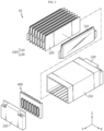
FIG. 2 is an exploded perspective view of a battery module according to the present disclosure. -
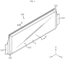
FIG. 3 is a diagram illustrating a battery cell included in the battery module according to the present disclosure. -
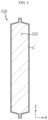
FIG. 4 is a diagram illustrating an exemplary cross-section taken along line B-B' inFIG. 3 . -
FIG. 5 is a diagram illustrating a swelling absorption pad included in a battery module and two battery cells positioned on both sides thereof according to the present disclosure. -
FIGS. 6 and7 are diagrams illustrating exemplary cross-sections taken along line A-A' inFIG. 1 . -
FIG. 8 is a diagram illustrating a bus-bar assembly included in a battery module according to the present disclosure. -
FIG. 9 is a diagram illustrating a battery pack according to the present disclosure. -
FIG. 10 is a diagram illustrating a vehicle according to the present disclosure. - Hereinafter, preferred embodiments of the present disclosure will be described in detail with reference to the accompanying drawings. The accompanying drawings illustrate a preferred embodiment of the present disclosure and, together with the detailed description of the invention below, serve to provide further understanding of the technical idea of the present disclosure, and thus, the present disclosure is not construed as being limited to the drawings. The same reference numerals indicate the same elements. In addition, in the drawings, the thickness, proportions, and dimensions of elements are exaggerated for effective explanation of technical content.
- It should be understood that the terms used in the specification and the appended claims should not be construed as limited to general and dictionary meanings, but interpreted based on the meanings and concepts corresponding to technical aspects of the present disclosure on the basis of the principle that the inventor is allowed to define terms appropriately for the best explanation.
- Although terms indicating directions such as upward, downward, left, right, forward, and backward are used in this specification, it is obvious to those skilled in the art that these terms are only for convenience of explanation and may vary depending on the location of the target object or the location of the observer.
- Therefore, the configurations proposed in the embodiments and drawings of this specification indicate only the most preferable embodiment of the present disclosure and do not represent all technical ideas of the present disclosure, so it should be understood that various equivalents and modifications could be made thereto at the time of filing the application.
-
FIG. 1 is a diagram illustrating the appearance of a battery module according to the present disclosure.FIG. 2 is an exploded perspective view of a battery module according to the present disclosure.FIG. 3 is a diagram illustrating a battery cell included in the battery module according to the present disclosure.FIG. 4 is a diagram illustrating an exemplary cross-section taken along line B-B' inFIG. 3 . - Referring to
FIGS. 1 to 4 , thebattery module 10 according to the present disclosure may include acell stack 100 and amodule case 200. - The
cell stack 100 may include a plurality ofbattery cell 110 stacked in at least one direction. - Each of the
battery cells 110 may be the secondary battery. Thebattery cell 110 may include an electrode assembly, anelectrode lead 113 connected to the electrode assembly, and the battery case that is sealed such that the electrode assembly is accommodated therein and such that theelectrode lead 113 extends to the outside thereof. An electrolyte may be accommodated inside the battery case. In particular, thebattery cell 110 provided in thecell stack 100 may be a pouch-type secondary battery. Thecell stack 100 may be configured such that a plurality of pouch-type secondary batteries is arranged side by side in the horizontal direction while their wide surfaces face each other in an upright state. - At least one of the plurality of
battery cell 110 may have a coating layer C formed on the surface thereof. The coating layer C may be coated on the entire surface of thebattery cell 110. The coating layer C may be provided on the surface of each of all thebattery cell 110. - The battery case may include an
accommodation portion 111 accommodating the electrode assembly and a sealingportion 112 configured to extend outwards from the perimeter of theaccommodation portion 111 so as to seal theaccommodation portion 111. The coating layer C may be provided on the entirety of the remaining surface of thebattery cell 110, excluding theelectrode lead 113. That is, the coating layer C may be configured to cover both theaccommodation portion 111 and the sealingportion 112 of the pouch case. As described above, if the coating layer C is provided on the entire area of thebattery cell 110, excluding theelectrode lead 113 for electrical connection, the fire resistance of thebattery cell 110 may be improved without affecting the electrical connection. - In another aspect, the coating layer C may also be provided on the portion of the
electrode lead 113. The coating layer C may be configured to cover the remaining area of theelectrode lead 113, excluding the area that is to be coupled to other components (e.g., components such as a bus-bar, an electrode lead of an adjacent battery cell, terminals, and the like). In this case, the fire resistance of thebattery cell 110 may be further improved. However, the present disclosure is not limited thereto, and the coating layer C may be provided only in theaccommodation portion 111 of the pouch case. - The coating layer C may be formed by applying paint to the surface of the
battery cell 110 in a spraying method. However, in addition thereto, the coating layer C may be provided on the surface of thebattery cell 110 in various other ways. - The coating layer C may be a fire-resistant coating layer C. The coating layer C may include a silica material. The coating layer C may include an alumina material. The coating layer C may include a magnesia material.
- The swelling
absorption pad 120 may be disposed between the plurality ofbattery cell 110. The swellingabsorption pad 120 may be disposed between twoadjacent battery cell 110. The swellingabsorption pad 120 may be disposed between every twoadjacent battery cells 110. The swellingabsorption pad 120 may be configured in a plate shape. - The swelling
absorption pad 120 may include an elastic material. The swellingabsorption pad 120 may include a heat-resistant material capable of withstanding flame or heat at a predetermined level or more. The swellingabsorption pad 120 may include a polyurethane material. The swellingabsorption pad 120 may include a silicone material. - According to this configuration of the present disclosure, the swelling
absorption pad 120 may absorb or suppress the pressure generated by swelling of thebattery cell 110. In another aspect, according to this configuration of the present disclosure, it is possible to prevent a problem with acceleration of thermal runaway caused by the swelling. In another aspect, according to this configuration of the present disclosure, the thermal chain reaction in which the flame and/or heat generated by a thermal event occurring in aspecific battery cell 110 transfer to otheradjacent battery cells 110 may be delayed or prevented. - In particular, although the pouch-type secondary battery may be relatively vulnerable to flame and/or heat, compared to the can-type battery, due to the nature of the exterior case, the coating layer C according to the present disclosure may be formed on the surface of the exterior case of the pouch, thereby delaying or preventing the above-mentioned thermal chain reaction.
- The
module case 200 may be configured to accommodate thecell stack 100. Themodule case 200 may be configured to have an accommodation space capable of accommodating thecell stack 100. Themodule case 200 may include acase body 210 comprised of four covers constituting respective surfaces substantially in the shape of a square pillar, and a pair ofend cover 220 for covering the front and back faces of thecell stack 100. -
FIG. 5 is a diagram illustrating a swelling absorption pad included in a battery module and two battery cells positioned on both sides thereof according to the present disclosure. - Referring to
FIG. 5 , the twobattery cells 110 positioned on both sides of the swellingabsorption pad 120 may have coating layers C, respectively, on the surfaces facing each other. - Referring to
FIG. 5 , the swellingabsorption pad 120 may have a larger area than the surface of thebattery cell 110 that faces the swellingabsorption pad 120. - If a battery case provided in the
battery cell 110 includes anaccommodation portion 111 that accommodates the electrode assembly and a sealingportion 112 that seals theaccommodation portion 111, the twobattery cells 110 positioned on both sides of the swellingabsorption pad 120 may have coating layers C on the area corresponding to theaccommodation portion 111. The swellingabsorption pad 120 may have a larger area than theaccommodation portion 111 corresponding thereto. The swellingabsorption pad 120 may be configured to cover theentire accommodation portion 111. -
FIGS. 6 and7 are diagrams illustrating exemplary cross-sections taken along line A-A' inFIG. 1 . - Referring to
FIGS. 6 and7 , themodule case 200 may have afirst accommodation portion 201 in which theswelling absorption pad 120 is accommodated. Themodule case 200 may have thefirst accommodation portion 201 on the inner surface of thecase body 210. - Referring to
FIG. 6 , thefirst accommodation portion 201 may be provided at the position corresponding to the swellingabsorption pad 120. Thefirst accommodation portion 201 may be provided on the inner surface of at least one of the upper and lower portions of themodule case 200. Thefirst accommodation portion 201 may be configured in the form of a groove extending substantially in a straight line from one end of themodule case 200 to the other end. Thefirst accommodation portion 201 may be provided to correspond to the number ofswelling absorption pad 120. - According to this configuration of the present disclosure, the swelling
absorption pad 120 may more effectively absorb or suppress the pressure generated by swelling of thebattery cell 110. This is due to the fact that the swellingabsorption pad 120 is accommodated in thefirst accommodation portion 201 of themodule case 200 and fixed stably. In another aspect, according to this configuration, the thermal propagation betweenadjacent battery cells 110 may be prevented more effectively. This is due to the fact that an empty space is prevented from being formed between the swellingabsorption pad 120 and the inner surface of themodule housing 200. - In addition, referring to
FIG. 2 as well, when storing the assembly of thecell stack 100 and the swellingabsorption pad 120 inside themodule case 200, a portion of the swellingabsorption pad 120 may be preferentially received in one end of thefirst accommodation portion 201 and then pushed toward the other end, so that the entirety of the assembly may slide to be accommodated therein. - Referring to
FIG. 7 , thebattery module 10 may include a supplementaryswelling absorption pad 121 disposed between thecell stack 100 and themodule case 200. Thebattery module 10 may include two supplementaryswelling absorption pads 121 between the left face of the cell stack 100 (in the -X-axis direction) and the left inner surface of the module case 200 (in the -X-axis direction), and between the right face of the cell stack 100 (in the X-axis direction) and the right inner surface of the module case 200 (in the X-axis direction), respectively. Themodule case 200 may have a second accommodation portion 202 in which the supplementaryswelling absorption pad 121 is accommodated. The second accommodation portion 202 may be provided at the position corresponding to the supplementaryswelling absorption pad 121. In this case, thefirst accommodation portion 201 may be provided selectively. - According to this configuration of the present disclosure, the supplementary
swelling absorption pad 121 may delay or prevent a thermal chain reaction in which the flame and/or heat generated by the thermal runaway occurring in thebattery cell 110 transfer to themodule case 200. Referring toFIG. 2 as well, when storing the assembly of thecell stack 100, the swellingabsorption pad 120, and the supplementaryswelling absorption pad 121 stacked on each other inside themodule case 200, a portion of the supplementaryswelling absorption pad 121 may be preferentially received in one end of the second accommodation portion 202 and then pushed toward the other end, so that the entirety of the assembly may slide to be accommodated therein. -
FIG. 8 is a diagram illustrating a bus-bar assembly 400 included in abattery module 10 according to the present disclosure. - Referring to
FIG. 8 , thebattery module 10 may include a bus-bar assembly 400. - The bus-
bar assembly 400 may include a bus-bar 420 that electrically connects a plurality ofbattery cell 110 and a bus-bar frame 410 on which the bus-bar 420 is seated. - The bus-
bar frame 410 may have a bus-bar seating portion 411, an electrodelead accommodation portion 412 in which theelectrode lead 113 is accommodated, and athird accommodation portion 413. - Referring to
FIG. 2 together, thethird accommodation portion 413 may receive one end of the swellingabsorption pad 120 in the longitudinal direction thereof (the Y-axis direction). Thethird accommodation portion 413 may be a groove that extends in the height direction (the Z-axis direction) of the bus-bar frame 410. Thethird accommodation portion 413 may be provided on the inner surface of the bus-bar frame 410. Thethird accommodation portion 413 may be configured in the form of a groove recessed in the +Y-axis direction from the substantially flat inner surface of the bus-bar frame 410 so as to correspond to the shape of the swellingabsorption pad 120. Thethird accommodation portion 413 may be configured in the form of a groove recessed in the +Y-axis direction from the protruding portion formed substantially in a trapezoidal pillar shape on the inner surface of the bus-bar frame so as to correspond to the shape of the swellingabsorption pad 120. However, thethird accommodation portion 413 may be configured in the form of a hole passing through the swellingabsorption pad 120, as well as the groove. - According to this configuration of the present disclosure, the swelling
absorption pad 120 may be fixed more stably by thethird accommodation portion 413 of the bus-bar frame 410, as well as thefirst accommodation portion 201 of themodule case 200. -
FIG. 9 is a diagram illustrating a battery pack according to the present disclosure. - Referring to
FIG. 9 , thebattery pack 2 may include one ormore battery modules 10 according to the present disclosure described above. In addition, thebattery pack 2 according to the present disclosure may further include, in addition to thebattery module 10, various other elements i.e., elements ofvarious battery packs 2 such as a BMS, a bus-bar, a pack case, a relay, a current sensor, and the like, which are well known at the time of filing the present disclosure. -
FIG. 10 is a diagram illustrating a vehicle according to the present disclosure. - Referring to
FIG. 10 , thevehicle 1 may include one ormore battery packs 2 according to the present disclosure described above. In addition, thevehicle 1 according to the present disclosure may further include various other elements included in thevehicle 1, in addition to the battery packs 2. For example, thevehicle 1 according to the present disclosure may further include a vehicle body, a motor, a control device such as an ECU (electronic control unit), and the like, in addition to thebattery pack 2, according to the present disclosure. - As described above, although the present disclosure has been described based on the preferred embodiments with reference to the accompanying drawings, it is obvious to those skilled in the art will that various modified embodiments may be implemented within the technical scope of the present disclosure. Therefore, the scope of the present disclosure should be construed according to the claims described to include various modifications.
-
- 1: Vehicle
- 2: Battery pack
- 10: Battery module
- 100: Cell stack
- 110: Battery cell
- 111: Accommodation portion
- 112: Sealing portion
- 113: Electrode lead
- 120: Swelling absorption pad
- 121: Supplementary swelling absorption pad
- 200: Module case
- 201: First accommodation portion
- 202: Second accommodation portion
- 210: Case body
- 220: End cover
- 400: Bus-bar assembly
- 410: Bus-bar frame
- 411: Bus-bar seating portion
- 412: Electrode lead accommodation portion
- 413: Third accommodation portion
- 420: Bus-bar
- Coating layer C
Claims (13)
- A battery module comprising:a cell stack comprising a plurality of battery cells stacked in at least one direction; anda module case configured to accommodate the cell stack,wherein the at least one of the plurality of battery cells comprisesa coating layer on the surface thereof.
- The battery module according to claim 1,wherein the coating layer iscoated on the entire surface of the battery cell.
- The battery module according to claim 1,wherein the coating layer isprovided on the surfaces of all battery cells included in the cell stack.
- The battery module according to claim 1,wherein the cell stack comprisesa swelling absorption pad disposed between the plurality of battery cells.
- The battery module according to claim 4,
wherein two battery cells positioned on both sides of the swelling absorption pad comprise the coating layers provided at positions corresponding to each other. - The battery module according to claim 1,wherein the coating layer isa fire-resistant coating layer.
- The battery module according to claim 1,wherein the coating layer comprisesa silica material.
- The battery module according to claim 4,wherein the swelling absorption pad isdisposed in every space between adjacent battery cells.
- The battery module according to claim 4,wherein the swelling absorption pad isa thermal pad with elasticity and heat resistance.
- The battery module according to claim 4,wherein the swelling absorption pad comprisessilicon.
- The battery module according to claim 4,wherein the swelling absorption pad hasan area greater than the surface of the battery cell facing the swelling absorption pad.
- A battery pack comprising the battery module according to any one of claims 1 to 11.
- A vehicle comprising a battery pack according to claim 12.
Applications Claiming Priority (3)
| Application Number | Priority Date | Filing Date | Title |
|---|---|---|---|
| KR20220167707 | 2022-12-05 | ||
| KR1020230043169A KR20240083793A (en) | 2022-12-05 | 2023-03-31 | Battery module, battery pack and vehicle comprising the same |
| PCT/KR2023/018110 WO2024122908A1 (en) | 2022-12-05 | 2023-11-10 | Battery module, and battery pack and vehicle comprising same |
Publications (2)
| Publication Number | Publication Date |
|---|---|
| EP4579911A1 true EP4579911A1 (en) | 2025-07-02 |
| EP4579911A4 EP4579911A4 (en) | 2026-01-21 |
Family
ID=91379715
Family Applications (1)
| Application Number | Title | Priority Date | Filing Date |
|---|---|---|---|
| EP23900927.7A Pending EP4579911A4 (en) | 2022-12-05 | 2023-11-10 | BATTERY MODULE AS WELL AS BATTERY PACK AND VEHICLE WITH IT |
Country Status (4)
| Country | Link |
|---|---|
| EP (1) | EP4579911A4 (en) |
| JP (1) | JP2025530788A (en) |
| CN (1) | CN119452513A (en) |
| WO (1) | WO2024122908A1 (en) |
Family Cites Families (15)
| Publication number | Priority date | Publication date | Assignee | Title |
|---|---|---|---|---|
| DE102010034825A1 (en) * | 2010-08-19 | 2012-02-23 | Li-Tec Battery Gmbh | Electrochemical energy storage |
| KR101510076B1 (en) * | 2012-09-24 | 2015-04-10 | 주식회사 엘지화학 | Battery Cell Coated with Sprayed Paint |
| KR102048359B1 (en) * | 2015-11-24 | 2020-01-08 | 주식회사 엘지화학 | Pouch-typed Battery Case Having Self-Healing Coating Layer and Pouch-typed Battery Cell Having the Same |
| KR101866862B1 (en) * | 2016-11-29 | 2018-07-23 | 율촌화학 주식회사 | Cell pouch with improved moldability and method of preparing the same |
| JP6885791B2 (en) * | 2017-06-05 | 2021-06-16 | 積水化学工業株式会社 | Thermal runaway prevention sheet |
| JP2018206604A (en) * | 2017-06-05 | 2018-12-27 | 積水化学工業株式会社 | Cell, battery module, battery pack, and battery |
| US11476532B2 (en) * | 2018-02-27 | 2022-10-18 | Panasonic Intellectual Property Management Co., Ltd. | Battery module |
| JP2019147357A (en) * | 2018-02-28 | 2019-09-05 | リンテック株式会社 | Flame retardant heat insulation sheet and electricity storage module |
| US11482752B2 (en) * | 2018-10-24 | 2022-10-25 | HHeLI, LLC | Polymer dipped pouch cell |
| KR102762534B1 (en) * | 2019-03-04 | 2025-02-03 | 주식회사 엘지에너지솔루션 | A battery module comprising a pad composite having swelling absorption and heat shielding function, a battery pack and a vehicle comprising the same |
| JP2023534746A (en) | 2020-07-23 | 2023-08-10 | ビーエーエスエフ ソシエタス・ヨーロピア | Synthesis of linear polyoxazolidinones using uretdione as diisocyanate component |
| JP7636439B2 (en) * | 2020-08-31 | 2025-02-26 | エルジー エナジー ソリューション リミテッド | Battery module and battery pack including same |
| KR20220167707A (en) | 2021-06-14 | 2022-12-21 | 사회복지법인 삼성생명공익재단 | Biomarker for diagnosing X-linked dominant Charcot-Marie-Tooth disease and uses thereof |
| CN216563355U (en) * | 2021-11-26 | 2022-05-17 | 微宏动力系统(湖州)有限公司 | Battery core, battery module and battery pack |
| JP7712036B2 (en) * | 2022-05-25 | 2025-07-23 | エルジー エナジー ソリューション リミテッド | Secondary battery module and secondary battery used therein |
-
2023
- 2023-11-10 JP JP2025513098A patent/JP2025530788A/en active Pending
- 2023-11-10 CN CN202380050623.7A patent/CN119452513A/en active Pending
- 2023-11-10 WO PCT/KR2023/018110 patent/WO2024122908A1/en not_active Ceased
- 2023-11-10 EP EP23900927.7A patent/EP4579911A4/en active Pending
Also Published As
| Publication number | Publication date |
|---|---|
| CN119452513A (en) | 2025-02-14 |
| EP4579911A4 (en) | 2026-01-21 |
| WO2024122908A1 (en) | 2024-06-13 |
| JP2025530788A (en) | 2025-09-17 |
Similar Documents
| Publication | Publication Date | Title |
|---|---|---|
| KR102832690B1 (en) | Battery module with improved safety | |
| KR102920773B1 (en) | Battery cell, battery module, battery pack and vehicle including the same | |
| JP2024527297A (en) | Battery pack and automobile including same | |
| KR102946788B1 (en) | Battery module, battery pack and vehicle including the same | |
| EP4401218A1 (en) | Battery module | |
| EP4685933A1 (en) | Battery pack | |
| EP4576385A1 (en) | Battery module | |
| EP4567996A2 (en) | Battery module | |
| EP4401191B1 (en) | Battery module | |
| KR102910589B1 (en) | Battery module | |
| KR20250038076A (en) | Battery pack | |
| EP4576384A1 (en) | Battery pack | |
| EP4468499A1 (en) | Battery module, and battery pack and vehicle comprising same | |
| CN224248776U (en) | Battery cell assembly, battery module comprising same, battery pack and vehicle | |
| KR20240083793A (en) | Battery module, battery pack and vehicle comprising the same | |
| EP4742404A1 (en) | Battery module | |
| EP4730490A1 (en) | Battery pack | |
| CN119452513A (en) | Battery module, battery pack and vehicle including the battery module | |
| EP4715988A1 (en) | Battery pack | |
| KR102840487B1 (en) | Battery pack | |
| EP4629423A1 (en) | Battery pack | |
| EP4661179A1 (en) | Battery assembly | |
| EP4632918A1 (en) | Battery pack | |
| EP4579939A1 (en) | Battery module | |
| EP4685966A1 (en) | Battery assembly |
Legal Events
| Date | Code | Title | Description |
|---|---|---|---|
| STAA | Information on the status of an ep patent application or granted ep patent |
Free format text: STATUS: THE INTERNATIONAL PUBLICATION HAS BEEN MADE |
|
| PUAI | Public reference made under article 153(3) epc to a published international application that has entered the european phase |
Free format text: ORIGINAL CODE: 0009012 |
|
| STAA | Information on the status of an ep patent application or granted ep patent |
Free format text: STATUS: REQUEST FOR EXAMINATION WAS MADE |
|
| 17P | Request for examination filed |
Effective date: 20250327 |
|
| AK | Designated contracting states |
Kind code of ref document: A1 Designated state(s): AL AT BE BG CH CY CZ DE DK EE ES FI FR GB GR HR HU IE IS IT LI LT LU LV MC ME MK MT NL NO PL PT RO RS SE SI SK SM TR |
|
| A4 | Supplementary search report drawn up and despatched |
Effective date: 20251223 |
|
| RIC1 | Information provided on ipc code assigned before grant |
Ipc: H01M 50/242 20210101AFI20251217BHEP Ipc: H01M 50/249 20210101ALI20251217BHEP Ipc: H01M 50/204 20210101ALI20251217BHEP Ipc: H01M 50/124 20210101ALI20251217BHEP Ipc: H01M 50/24 20210101ALI20251217BHEP Ipc: H01M 50/293 20210101ALI20251217BHEP |
|
| DAV | Request for validation of the european patent (deleted) | ||
| DAX | Request for extension of the european patent (deleted) |