EP4579902A1 - Cap assembly for secondary battery, secondary battery, battery pack, and moving means - Google Patents
Cap assembly for secondary battery, secondary battery, battery pack, and moving means Download PDFInfo
- Publication number
- EP4579902A1 EP4579902A1 EP24849552.5A EP24849552A EP4579902A1 EP 4579902 A1 EP4579902 A1 EP 4579902A1 EP 24849552 A EP24849552 A EP 24849552A EP 4579902 A1 EP4579902 A1 EP 4579902A1
- Authority
- EP
- European Patent Office
- Prior art keywords
- secondary battery
- top cap
- cap
- assembly
- cap assembly
- Prior art date
- Legal status (The legal status is an assumption and is not a legal conclusion. Google has not performed a legal analysis and makes no representation as to the accuracy of the status listed.)
- Pending
Links
Images



Classifications
-
- H—ELECTRICITY
- H01—ELECTRIC ELEMENTS
- H01M—PROCESSES OR MEANS, e.g. BATTERIES, FOR THE DIRECT CONVERSION OF CHEMICAL ENERGY INTO ELECTRICAL ENERGY
- H01M50/00—Constructional details or processes of manufacture of the non-active parts of electrochemical cells other than fuel cells, e.g. hybrid cells
- H01M50/10—Primary casings; Jackets or wrappings
- H01M50/147—Lids or covers
- H01M50/148—Lids or covers characterised by their shape
- H01M50/152—Lids or covers characterised by their shape for cells having curved cross-section, e.g. round or elliptic
-
- H—ELECTRICITY
- H01—ELECTRIC ELEMENTS
- H01M—PROCESSES OR MEANS, e.g. BATTERIES, FOR THE DIRECT CONVERSION OF CHEMICAL ENERGY INTO ELECTRICAL ENERGY
- H01M50/00—Constructional details or processes of manufacture of the non-active parts of electrochemical cells other than fuel cells, e.g. hybrid cells
- H01M50/10—Primary casings; Jackets or wrappings
- H01M50/147—Lids or covers
- H01M50/155—Lids or covers characterised by the material
-
- H—ELECTRICITY
- H01—ELECTRIC ELEMENTS
- H01M—PROCESSES OR MEANS, e.g. BATTERIES, FOR THE DIRECT CONVERSION OF CHEMICAL ENERGY INTO ELECTRICAL ENERGY
- H01M10/00—Secondary cells; Manufacture thereof
- H01M10/60—Heating or cooling; Temperature control
- H01M10/64—Heating or cooling; Temperature control characterised by the shape of the cells
- H01M10/643—Cylindrical cells
-
- H—ELECTRICITY
- H01—ELECTRIC ELEMENTS
- H01M—PROCESSES OR MEANS, e.g. BATTERIES, FOR THE DIRECT CONVERSION OF CHEMICAL ENERGY INTO ELECTRICAL ENERGY
- H01M10/00—Secondary cells; Manufacture thereof
- H01M10/60—Heating or cooling; Temperature control
- H01M10/65—Means for temperature control structurally associated with the cells
- H01M10/653—Means for temperature control structurally associated with the cells characterised by electrically insulating or thermally conductive materials
-
- H—ELECTRICITY
- H01—ELECTRIC ELEMENTS
- H01M—PROCESSES OR MEANS, e.g. BATTERIES, FOR THE DIRECT CONVERSION OF CHEMICAL ENERGY INTO ELECTRICAL ENERGY
- H01M10/00—Secondary cells; Manufacture thereof
- H01M10/60—Heating or cooling; Temperature control
- H01M10/65—Means for temperature control structurally associated with the cells
- H01M10/655—Solid structures for heat exchange or heat conduction
- H01M10/6551—Surfaces specially adapted for heat dissipation or radiation, e.g. fins or coatings
-
- H—ELECTRICITY
- H01—ELECTRIC ELEMENTS
- H01M—PROCESSES OR MEANS, e.g. BATTERIES, FOR THE DIRECT CONVERSION OF CHEMICAL ENERGY INTO ELECTRICAL ENERGY
- H01M50/00—Constructional details or processes of manufacture of the non-active parts of electrochemical cells other than fuel cells, e.g. hybrid cells
- H01M50/10—Primary casings; Jackets or wrappings
- H01M50/102—Primary casings; Jackets or wrappings characterised by their shape or physical structure
- H01M50/107—Primary casings; Jackets or wrappings characterised by their shape or physical structure having curved cross-section, e.g. round or elliptic
-
- H—ELECTRICITY
- H01—ELECTRIC ELEMENTS
- H01M—PROCESSES OR MEANS, e.g. BATTERIES, FOR THE DIRECT CONVERSION OF CHEMICAL ENERGY INTO ELECTRICAL ENERGY
- H01M50/00—Constructional details or processes of manufacture of the non-active parts of electrochemical cells other than fuel cells, e.g. hybrid cells
- H01M50/10—Primary casings; Jackets or wrappings
- H01M50/147—Lids or covers
-
- H—ELECTRICITY
- H01—ELECTRIC ELEMENTS
- H01M—PROCESSES OR MEANS, e.g. BATTERIES, FOR THE DIRECT CONVERSION OF CHEMICAL ENERGY INTO ELECTRICAL ENERGY
- H01M50/00—Constructional details or processes of manufacture of the non-active parts of electrochemical cells other than fuel cells, e.g. hybrid cells
- H01M50/10—Primary casings; Jackets or wrappings
- H01M50/183—Sealing members
-
- H—ELECTRICITY
- H01—ELECTRIC ELEMENTS
- H01M—PROCESSES OR MEANS, e.g. BATTERIES, FOR THE DIRECT CONVERSION OF CHEMICAL ENERGY INTO ELECTRICAL ENERGY
- H01M50/00—Constructional details or processes of manufacture of the non-active parts of electrochemical cells other than fuel cells, e.g. hybrid cells
- H01M50/20—Mountings; Secondary casings or frames; Racks, modules or packs; Suspension devices; Shock absorbers; Transport or carrying devices; Holders
- H01M50/204—Racks, modules or packs for multiple batteries or multiple cells
- H01M50/207—Racks, modules or packs for multiple batteries or multiple cells characterised by their shape
- H01M50/213—Racks, modules or packs for multiple batteries or multiple cells characterised by their shape adapted for cells having curved cross-section, e.g. round or elliptic
-
- H—ELECTRICITY
- H01—ELECTRIC ELEMENTS
- H01M—PROCESSES OR MEANS, e.g. BATTERIES, FOR THE DIRECT CONVERSION OF CHEMICAL ENERGY INTO ELECTRICAL ENERGY
- H01M50/00—Constructional details or processes of manufacture of the non-active parts of electrochemical cells other than fuel cells, e.g. hybrid cells
- H01M50/20—Mountings; Secondary casings or frames; Racks, modules or packs; Suspension devices; Shock absorbers; Transport or carrying devices; Holders
- H01M50/249—Mountings; Secondary casings or frames; Racks, modules or packs; Suspension devices; Shock absorbers; Transport or carrying devices; Holders specially adapted for aircraft or vehicles, e.g. cars or trains
-
- H—ELECTRICITY
- H01—ELECTRIC ELEMENTS
- H01M—PROCESSES OR MEANS, e.g. BATTERIES, FOR THE DIRECT CONVERSION OF CHEMICAL ENERGY INTO ELECTRICAL ENERGY
- H01M50/00—Constructional details or processes of manufacture of the non-active parts of electrochemical cells other than fuel cells, e.g. hybrid cells
- H01M50/30—Arrangements for facilitating escape of gases
-
- H—ELECTRICITY
- H01—ELECTRIC ELEMENTS
- H01M—PROCESSES OR MEANS, e.g. BATTERIES, FOR THE DIRECT CONVERSION OF CHEMICAL ENERGY INTO ELECTRICAL ENERGY
- H01M2220/00—Batteries for particular applications
- H01M2220/20—Batteries in motive systems, e.g. vehicle, ship, plane
-
- Y—GENERAL TAGGING OF NEW TECHNOLOGICAL DEVELOPMENTS; GENERAL TAGGING OF CROSS-SECTIONAL TECHNOLOGIES SPANNING OVER SEVERAL SECTIONS OF THE IPC; TECHNICAL SUBJECTS COVERED BY FORMER USPC CROSS-REFERENCE ART COLLECTIONS [XRACs] AND DIGESTS
- Y02—TECHNOLOGIES OR APPLICATIONS FOR MITIGATION OR ADAPTATION AGAINST CLIMATE CHANGE
- Y02E—REDUCTION OF GREENHOUSE GAS [GHG] EMISSIONS, RELATED TO ENERGY GENERATION, TRANSMISSION OR DISTRIBUTION
- Y02E60/00—Enabling technologies; Technologies with a potential or indirect contribution to GHG emissions mitigation
- Y02E60/10—Energy storage using batteries
-
- Y—GENERAL TAGGING OF NEW TECHNOLOGICAL DEVELOPMENTS; GENERAL TAGGING OF CROSS-SECTIONAL TECHNOLOGIES SPANNING OVER SEVERAL SECTIONS OF THE IPC; TECHNICAL SUBJECTS COVERED BY FORMER USPC CROSS-REFERENCE ART COLLECTIONS [XRACs] AND DIGESTS
- Y02—TECHNOLOGIES OR APPLICATIONS FOR MITIGATION OR ADAPTATION AGAINST CLIMATE CHANGE
- Y02P—CLIMATE CHANGE MITIGATION TECHNOLOGIES IN THE PRODUCTION OR PROCESSING OF GOODS
- Y02P70/00—Climate change mitigation technologies in the production process for final industrial or consumer products
- Y02P70/50—Manufacturing or production processes characterised by the final manufactured product
Definitions
- the present invention relates to a cap assembly for a secondary battery, a secondary battery, a battery pack, and a transportation means.
- a secondary battery refers to a battery that is chargeable and dischargeable unlike a primary battery that is not chargeable, and the secondary battery is widely used in the field of high-tech electronic devices such as a phone, a laptop computer and a camcorder.
- the stability of the secondary battery may be secured by a test for stability in which one surface is compressed with a press to measure an internal short circuit.
- the secondary battery is classified into a cylindrical battery and a prismatic battery in which an electrode assembly is embedded in a cylindrical or prismatic metal battery case, and a pouch-type battery in which an electrode assembly is embedded in a pouch-type battery case made of an aluminum laminate sheet.
- the electrode assembly embedded in the battery case is a chargeable/dischargeable power generating device having a stack structure of a positive electrode/a separator/a negative electrode, and is classified into a folding-type electrode assembly (jelly-roll) in which long sheet-like positive electrode and negative electrode coated with active materials are wound with a separator interposed therebetween, and a stack-type electrode assembly in which a plurality of positive electrodes and negative electrodes having predetermined sizes are sequentially stacked with separators interposed therebetween.
- the jelly-roll has the advantages of being easy to manufacture and having high energy density per weight. Consequently, the demand for cylindrical batteries including electrode assemblies with a jelly-roll structure is increasing.
- Cylindrical batteries include an electrode assembly with a jelly-roll structure, a battery case, and a cap assembly.
- the cap assembly is a structure that is coupled to an opening of the battery case into which the electrode assembly is inserted. Since the cap assembly seals the battery case, the gas inside the battery may not be discharged to the outside in a normal situation.
- Cylindrical batteries may undergo thermal runaway due to heat generated from a decomposition reaction of the electrode active materials included in the electrode assembly. If the cap assembly is not separated from the battery case at this time, the heat inside the battery case may damage the separator, cause short circuits of the positive electrode and negative electrodes, and lead to excessive current due to internal short circuits, potentially resulting in a fire or even an explosion.
- the internal pressure of the battery case may increase due to the heat and gas inside the battery case not being discharged, which may cause the battery case to rupture.
- the present invention is intended to provide a cap assembly for a secondary battery, a secondary battery, a battery pack, and a transportation means.
- An exemplary embodiment of the present invention provides a cap assembly for a secondary battery, the cap assembly including a top cap electrically connected to an outside and a gasket configured to surround an outer peripheral portion of the top cap, wherein the top cap has a thermally conductive layer provided on one surface.
- An exemplary embodiment of the present invention provides a secondary battery including an electrode assembly in which an electrode and a separator are wound; a case having a space into which the electrode assembly is introduced and having one side opened; and the above-described cap assembly coupled to the opened side of the case.
- An exemplary embodiment of the present invention provides a battery pack including the secondary battery.
- An exemplary embodiment of the present invention provides a transportation means including the battery pack.
- the cap assembly for a secondary battery, the secondary battery, the battery pack, and the transportation means can prevent the battery case from rupturing by the top cap being melted by the heat generated from the decomposition reaction of the electrode active materials and thus preventing the runaway phenomenon.
- the metal-based material may include silver, copper, aluminum, or the like
- the ceramic-based material may include silicon carbide (SiC), beryllium oxide (BeO), aluminum nitride (AlN), aluminum oxide (Al 2 O 3 ), or the like.
- the separator prevents an internal short circuit that may be generated when the positive electrode and the negative electrode come into contact with each other, and may include a porous material to facilitate migration of ions between the electrodes.
- the separator may include a base material layer made of a porous material.
- the base material layer may include, for example, any one selected from the group consisting of polyethylene (PE), polystyrene (PS), polypropylene (PP), and a copolymer of polyethylene (PE) and polypropylene (PP).
- the battery case 200 of the secondary battery 1 may have a structure in which one side is open (hereinafter, referred to as an opening portion) and the other side is sealed.
- the battery case 200 may be made of a lightweight conductive metal material such as aluminum or aluminum alloy.
- an electrode terminal may be coupled to a through hole provided on the other side of the battery case 200.
- the electrode terminal may be secured on an inner surface of the sealed portion of the battery case 200 by riveting.
- the battery case 200 and the cap assembly 300 have the same polarity, and the electrode terminal has a different electrode from those of the battery case 200 and the cap assembly 300.
- the electrode terminal is a positive electrode
- the battery case 200 and the cap assembly 300 may be negative electrodes.
- a battery pack 3 including any one of the secondary batteries described above is provided.
- a battery pack 3 including the secondary battery 1 in a pack housing 2 is shown.
- a transportation means including the battery pack described above is provided.
- the transportation means since the transportation means according to the above exemplary embodiment uses the battery pack having high output/high capacity, the transportation means is excellent in terms of stability and safety.
Landscapes
- Chemical & Material Sciences (AREA)
- Chemical Kinetics & Catalysis (AREA)
- Electrochemistry (AREA)
- General Chemical & Material Sciences (AREA)
- Engineering & Computer Science (AREA)
- Manufacturing & Machinery (AREA)
- Aviation & Aerospace Engineering (AREA)
- Sealing Battery Cases Or Jackets (AREA)
- Connection Of Batteries Or Terminals (AREA)
- Gas Exhaust Devices For Batteries (AREA)
Abstract
Description
- This application claims priority to and the benefit of
Korean Patent Application No. 10-2023-0100295 filed in the Korean Intellectual Property Office on August 1, 2023 - The present invention relates to a cap assembly for a secondary battery, a secondary battery, a battery pack, and a transportation means.
- In general, a secondary battery refers to a battery that is chargeable and dischargeable unlike a primary battery that is not chargeable, and the secondary battery is widely used in the field of high-tech electronic devices such as a phone, a laptop computer and a camcorder.
- The stability of the secondary battery may be secured by a test for stability in which one surface is compressed with a press to measure an internal short circuit.
- Depending on a shape of a battery case, the secondary battery is classified into a cylindrical battery and a prismatic battery in which an electrode assembly is embedded in a cylindrical or prismatic metal battery case, and a pouch-type battery in which an electrode assembly is embedded in a pouch-type battery case made of an aluminum laminate sheet.
- In addition, the electrode assembly embedded in the battery case is a chargeable/dischargeable power generating device having a stack structure of a positive electrode/a separator/a negative electrode, and is classified into a folding-type electrode assembly (jelly-roll) in which long sheet-like positive electrode and negative electrode coated with active materials are wound with a separator interposed therebetween, and a stack-type electrode assembly in which a plurality of positive electrodes and negative electrodes having predetermined sizes are sequentially stacked with separators interposed therebetween. Among these, the jelly-roll has the advantages of being easy to manufacture and having high energy density per weight. Consequently, the demand for cylindrical batteries including electrode assemblies with a jelly-roll structure is increasing.
- Cylindrical batteries include an electrode assembly with a jelly-roll structure, a battery case, and a cap assembly. The cap assembly is a structure that is coupled to an opening of the battery case into which the electrode assembly is inserted. Since the cap assembly seals the battery case, the gas inside the battery may not be discharged to the outside in a normal situation.
- Cylindrical batteries may undergo thermal runaway due to heat generated from a decomposition reaction of the electrode active materials included in the electrode assembly. If the cap assembly is not separated from the battery case at this time, the heat inside the battery case may damage the separator, cause short circuits of the positive electrode and negative electrodes, and lead to excessive current due to internal short circuits, potentially resulting in a fire or even an explosion.
- In addition, the internal pressure of the battery case may increase due to the heat and gas inside the battery case not being discharged, which may cause the battery case to rupture.
- In view of the problems of the related art described above, the present invention is intended to provide a cap assembly for a secondary battery, a secondary battery, a battery pack, and a transportation means.
- An exemplary embodiment of the present invention provides a cap assembly for a secondary battery, the cap assembly including a top cap electrically connected to an outside and a gasket configured to surround an outer peripheral portion of the top cap, wherein the top cap has a thermally conductive layer provided on one surface.
- An exemplary embodiment of the present invention provides a secondary battery including an electrode assembly in which an electrode and a separator are wound; a case having a space into which the electrode assembly is introduced and having one side opened; and the above-described cap assembly coupled to the opened side of the case.
- An exemplary embodiment of the present invention provides a battery pack including the secondary battery.
- An exemplary embodiment of the present invention provides a transportation means including the battery pack.
- The cap assembly for a secondary battery, the secondary battery, the battery pack, and the transportation means according to the exemplary embodiments of the present invention can prevent the battery case from rupturing by the top cap being melted by the heat generated from the decomposition reaction of the electrode active materials and thus preventing the runaway phenomenon.
-
-
FIG. 1(a) is a cross-sectional view showing a cap assembly according to an exemplary embodiment of the present invention, andFIG. 1(b) is a perspective view showing a top cap and a gasket according to an exemplary embodiment of the present invention. -
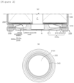
FIG. 2(a) is a cross-sectional view showing a secondary battery according to another exemplary embodiment of the present invention, andFIG. 2(b) is a plan view showing a top cap and a battery case according to another exemplary embodiment of the present invention. -
FIG. 3 is a cross-sectional view showing a secondary battery according to an exemplary embodiment of the present invention. -
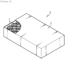
FIG. 4 is a perspective view showing a battery pack according to an exemplary embodiment of the present invention. -
FIG. 5 is a perspective view showing a transportation means according to an exemplary embodiment of the present invention. -
- 1: secondary battery
- 2: pack housing
- 3: battery pack
- 100: electrode assembly
- 200: battery case
- 210: beading portion
- 220: clamping portion
- 300a, 300b: cap assembly
- 310a, 310b: top cap
- 311: protrusion
- 312: rim portion
- 313: bridge
- 314: venting portion
- 320: safety vent
- 330: gasket
- 340: CID
- 350: CID gasket
- C: core part
- H: thermally conductive layer or thermally conductive material
- The detailed description of the present invention is intended to completely explain the present invention to one skilled in the art. Throughout the specification, unless explicitly described to the contrary, when one component "comprises (includes)" another component or "is characterized by" having a certain structure and a certain shape, this means that other components, structures, and shapes may be included without being excluded.
- The present invention may be variously modified and may have various exemplary embodiments, and specific exemplary embodiments will be described in detail in the detailed description. However, the description of the exemplary embodiments is not intended to limit the contents of the present invention, but it should be understood that the present invention is to cover all modifications, equivalents and alternatives falling within the spirit and technical scope of the present invention.
- Hereinafter, the present invention will be described in detail with reference to the drawings. However, it should be noted that the drawings are provided for illustrating the present invention, and the scope of the present invention is not limited by the drawings.
- A
secondary battery 1 according to an exemplary embodiment of the present invention includes anelectrode assembly 100, abattery case 200, and acap assembly secondary battery 1 according to an exemplary embodiment of the present invention is a cylindrical secondary battery. In thesecondary battery 1 according to an exemplary embodiment, acap assembly 300a may be coupled to an upper portion of thebattery case 200, and a positive electrode uncoated portion and a negative electrode uncoated portion provided on a positive electrode and a negative electrode of theelectrode assembly 100 may be provided in a short-axis direction of a positive electrode current collector and a negative electrode current collector, respectively. - In the
secondary battery 1 according to another exemplary embodiment, acap assembly 300b may be coupled to a lower portion of thebattery case 200. The positive electrode uncoated portion and the negative electrode uncoated portion of theelectrode assembly 100 may be provided in a long-axis direction of the positive electrode current collector and the negative electrode current collector, respectively. - In the case where the
cap assembly 300a is coupled to the upper portion of thebattery case 200, thecap assembly 300 may include atop cap 310, asafety vent 320, and agasket 330. When thecap assembly 300 is coupled to the lower portion of thebattery case 200, thecap assembly 300 may include atop cap 310 and agasket 330. - The
top cap 310 is located at the top of thecap assembly 300, and may protrude in an opposite direction to the center of thebattery case 200. - A
top cap 310a according to an exemplary embodiment may serve as an electrode terminal so that the protruding portion is electrically connected to the outside. For example, thetop cap 310a may serve as a positive electrode terminal. - Referring to
FIG. 1 , thetop cap 310a includes aprotrusion 311 protruding upward, arim portion 312 in contact with or surrounded by thesafety vent 320 described below, and abridge 313 connecting theprotrusion 311 and therim portion 312. - Referring to
FIG. 2 , thetop cap 310b according to another exemplary embodiment may be provided with a venting portion 314 that prevents an internal pressure from increasing beyond a preset value due to gas generated inside thebattery case 200. Specifically, thetop cap 310b may include aprotrusion 311, arim portion 312, and a venting portion 314, and the venting portion 314 may be located between theprotrusion 311 and therim portion 312. - The venting portion 314 refers to a region of the
top cap 310b, which has a thinner thickness compared to the surrounding region. The venting portion 314 is structurally vulnerable compared to the surrounding region. Therefore, if an abnormality occurs in the cylindrical secondary battery and the internal pressure of thebattery case 200 increases above a certain level, the venting portion 314 may rupture and gas generated inside thebattery case 200 may be discharged to the outside. - For example, the venting portion 314 may be formed by notching one side or both sides of the
top cap 310b to partially reduce the thickness of thetop cap 310b. - The
top cap 310 is provided with a thermally conductive layer (H) on a lower surface, i.e., a surface facing thesafety vent 320, and the thermally conductive layer (H) may include a material with a higher thermal conductivity than that of thetop cap 310. - In other words, the
cap assembly 300 may have the thermally conductive material coated on the lower surface of thetop cap 310, and the thermally conductive material may be a material with a higher thermal conductivity than that of thetop cap 310. For example, thetop cap 310 may include iron or stainless steel, and the thermally conductive layer (H) or thermally conductive material may include a material with a higher thermal conductivity than that of iron or stainless steel. - Preferably, the
top cap 310 may include iron, and the thermally conductive layer may include a material with a higher thermal conductivity than that of iron. - The thermally conductive layer (H) or thermally conductive material may be coated or laminated on a lower surface of the
protrusion 311 of thetop cap 310. A coating area of the thermally conductive material may be equal to or smaller than a lower surface area of theprotrusion 311. Preferably, the coating area of the thermally conductive material may be smaller than the lower surface area of theprotrusion 311. For example, the coating area of the thermally conductive material may be 30% to 70% based on 100% of the lower surface area of theprotrusion 311. - Alternatively, the thermally conductive layer (H) may have a thermal conductivity of 50 W/m-K or higher. The thermal conductivity refers to a thermal conductivity of the thermally conductive layer (H) itself, regardless of the type, amount, thickness, and the like of the material forming the thermally conductive layer (H).
- When the thermally conductive layer (H) or thermally conductive material satisfies the above thermal conductivity, if heat is generated in the
electrode assembly 100, the portion coated with the thermally conductive material is melted or ruptured earlier than a portion not coated with the thermally conductive material, resulting in dissipation of the heat inside thebattery case 200 to the outside. - In an exemplary embodiment, the thermally conductive material may include any one of a metal-based material, a ceramic-based material, a carbon-based material, and a polymer-based material.
- For example, the metal-based material may include silver, copper, aluminum, or the like, and the ceramic-based material may include silicon carbide (SiC), beryllium oxide (BeO), aluminum nitride (AlN), aluminum oxide (Al2O3), or the like.
- Furthermore, the thermally conductive layer or thermally conductive material may further include an electrically conductive material.
- The
gasket 330 may be located inside a crimpingportion 220 of thebattery case 200 described below. Thegasket 330 can increase a sealing force between thetop cap 310 and thebattery case 200. - The
safety vent 320 may be further included. Thesafety vent 320 is positioned below thetop cap 310 and may be electrically connected to thetop cap 310. At least a portion of a surface of thesafety vent 320 facing thetop cap 310 may be in contact with thetop cap 310. Thesafety vent 320 is in contact with thetop cap 310 for a certain length from its rim, and a portion excluding the contact length may be located away from thetop cap 310. The portion of thesafety vent 320 in contact with thetop cap 310 may be coupled with thegasket 330. - In this case, the
gasket 330 may be located inside the crimpingportion 220 of thebattery case 200. Thegasket 330 can increase a sealing force between thesafety vent 320 and thebattery case 200. - A spacing distance between the
safety vent 320 and thetop cap 310 may increase from a region of thesafety vent 320 in contact with thetop cap 310 toward the center of thesafety vent 320. - The
safety vent 320 may include a contact portion in contact with thetop cap 310, a central portion positioned at the center of thesafety vent 320 and in contact with the current interruptive device, and a connection portion connecting the contact portion and the central portion. Thesafety vent 320 may be provided with bent portions (or notches) at portions where the contact portion and the connection portion are in contact and the connection portion and the central portion are in contact. - In an exemplary embodiment, the
safety vent 320 may have an end portion perpendicular to an axial direction of thebattery case 200. In this case, thetop cap 310 may be provided perpendicular to the axial direction of thebattery case 200, like thesafety vent 320. That is, thesafety vent 320 and thetop cap 310 can be positioned horizontally. - In another exemplary embodiment, the
safety vent 320 may have an end portion bent to surround an outer circumferential surface of thetop cap 310. - In the
secondary battery 1 according to an exemplary embodiment of the present invention, gas is generated or heat is generated as theelectrode assembly 100 accommodated inside thebattery case 200 reacts with the electrolyte solution, thereby increasing an internal pressure. - When the internal pressure of the
secondary battery 1 increases, thesafety vent 320 receives force in a direction of thetop cap 310, and the bent portion ruptures, causing the gas inside thesecondary battery 1 to be discharged. - The current interruptive device (CID) 330 is positioned below the
safety vent 320, and at least a portion thereof may be connected to thesafety vent 320. - When the
safety vent 320 ruptures as the internal pressure of thesecondary battery 1 increases, the currentinterruptive device 330 is separated from thesafety vent 320 to interrupt the current. - More specifically, the current
interruptive device 330 may include a connection portion connected to thesafety vent 320 at a central portion and protruding in a direction in which thesafety vent 320 is positioned, an edge portion excluding the connection portion, and a coupling portion connecting the connection portion and the edge portion. The coupling portion is provided in plural, and the plurality of coupling portions may be positioned spaced apart from each other. - When the
safety vent 320 is deformed in the direction in which thetop cap 310 is positioned, the coupling portion may be disconnected and the connection portion may be separated from the edge portion. That is, the connection portion is separated in the direction of thetop cap 310 while being connected to thesafety vent 320. - A
CID gasket 350 surrounds an edge of the currentinterruptive device 330 and can electrically separate thesafety vent 320 from the edge portion and coupling portion other than the connection portion of the currentinterruptive device 330. - The
electrode assembly 100 includes a positive electrode, a separator, and a negative electrode. Theelectrode assembly 100 is a jelly-roll type chargeable/dischargeable power generating element that includes a positive electrode, a negative electrode, and a separator located between the positive electrode and the negative electrode and is wound. - In an exemplary embodiment, the
electrode assembly 100 may be a jelly-roll structure in which a negative electrode, a separator, and a positive electrode are sequentially stacked and wound, or a first separator, a negative electrode, a second separator, and a positive electrode are sequentially stacked and wound. - The positive electrode includes a positive electrode active material portion having a positive electrode active material applied to one surface or both surfaces of a positive electrode current collector and a positive electrode uncoated portion having no positive electrode active material applied thereto.
- The positive electrode current collector is a metal thin plate with excellent conductivity and may include, for example, an aluminum (Al) foil.
- The positive electrode active material may include a lithium cobalt oxide with a high operating voltage and excellent capacity characteristics, a lithium nickel oxide with a high reversible capacity and used to easily implement a large-capacity battery, a lithium nickel cobalt oxide where a part of nickel is substituted with cobalt, a lithium nickel cobalt metal oxide where a part of nickel is substituted with manganese, cobalt, or aluminum, a lithium manganese-based oxide excellent in thermal stability and low in cost, a lithium iron phosphate excellent in stability, and the like.
- The negative electrode includes a negative electrode active material portion having a negative electrode active material applied to one surface or both surfaces of a negative electrode current collector and a negative electrode uncoated portion having no negative electrode active material applied thereto.
- The negative electrode current collector may include a metal thin plate with excellent conductivity, for example, a copper (Cu) or nickel (Ni) foil.
- The negative electrode active material may be, for example, a carbon material such as crystalline carbon, amorphous carbon, carbon composite, or carbon fiber, lithium metal, a lithium alloy, or the like. In this case, the negative electrode active material may further include, for example, non-graphite-based SiO (silica), SiC (silicon carbide) or the like for high-capacity design.
- The
electrode assembly 100 according to an exemplary embodiment may have a positive electrode uncoated portion and a negative electrode uncoated portion provided in the short direction of the electrode current collector at both ends or in the middle of the positive electrode and negative electrode. In addition, a positive electrode tab and a negative electrode tab may be provided by being bonded to the positive electrode uncoated portion and the negative electrode uncoated portion. - The positive electrode tab and the negative electrode tab serve to transfer electrons collected in the current collectors to an external circuit, and may protrude in the same direction or opposite directions with respect to the electrode assembly of the jelly-roll structure.
- The
electrode assembly 100 according to another exemplary embodiment may have a positive electrode uncoated portion and a negative electrode uncoated portion provided in the long direction of the positive electrode current collector and the negative electrode current collector. The positive electrode uncoated portion and the negative electrode uncoated portion may be located at both ends in the short direction of the positive electrode current collector and the negative electrode current collector. - At least a portion of the positive electrode uncoated portion and the negative electrode uncoated portion may include a plurality of segments divided along a winding direction of the
electrode assembly 100. The plurality of segments can be bent in a direction in which a core portion of theelectrode assembly 100 is located. The plurality of bent segments can be overlapped in multiple layers. In this case, a first current collector and a second current collector can be combined in a region where the plurality of segments are overlapped in multiple layers. - In this case, the first current collector and the second current collector are included in both the
secondary batteries 1 according to an exemplary embodiment and another exemplary embodiment, and may be located on facing surfaces, i.e., an upper surface and a lower surface, located in a height direction of theelectrode assembly 100. - The first current collector and the second current collector are electrically connected to the
battery case 200. The first current collector can function as a medium for electrical connection between theelectrode assembly 100 and thebattery case 200. Either the first current collector or the second current collector can be welded and fixed to an inner wall of thebattery case 200. - The separator prevents an internal short circuit that may be generated when the positive electrode and the negative electrode come into contact with each other, and may include a porous material to facilitate migration of ions between the electrodes.
- In an exemplary embodiment, the separator may include a base material layer made of a porous material. The base material layer may include, for example, any one selected from the group consisting of polyethylene (PE), polystyrene (PS), polypropylene (PP), and a copolymer of polyethylene (PE) and polypropylene (PP).
- In another exemplary embodiment, the separator may include a safety reinforced separator (SRS). That is, the separator 130, 140 may include a base material layer made of a porous material and a coating layer coated and formed on the base material layer by applying a mixed slurry of inorganic particles and a binder polymer. Preferably, the coating layer includes ceramic particles and has a uniform pore structure formed by an interstitial volume between the ceramic particles that are a component of an active layer, in addition to a pore structure of the separator base material itself.
- The coating layer may include ceramic particles including at least one selected from the group consisting of alumina, silica, TiO2, SiC, and MgAl2O4. Such a coating layer is included, so that the safety of the electrode assembly can be enhanced. The coating layer may further include a lithium salt.
- The
battery case 200 may have a column structure with a space formed therein. The battery case 30 may accommodate theelectrode assembly 100 including electrodes and a separator and an electrolyte solution (not shown) in the internal space. - The
battery case 200 of thesecondary battery 1 according to an exemplary embodiment may have a structure in which one side is open (hereinafter, referred to as an opening portion) and the other side is sealed. - The
battery case 200 of thesecondary battery 1 according to another exemplary embodiment may have a structure in which one side is open and the other side is sealed (sealed portion) except for a through hole in a center. - Here, one side and the other side of the
battery case 200 refer to end portions located at an upper portion and a lower portion along the height direction of theelectrode assembly 100 orsecondary battery 1. - One side, which is open, of the
battery case 200 may be provided with abeading portion 210 folded toward the center of thesecondary battery 1. Thebattery case 200 may be provided with a crimpingportion 220 between thebeading portion 210 and the opening. - The
battery case 200 may be made of a lightweight conductive metal material such as aluminum or aluminum alloy. - In the
secondary battery 1 according to another exemplary embodiment, an electrode terminal may be coupled to a through hole provided on the other side of thebattery case 200. For example, the electrode terminal may be secured on an inner surface of the sealed portion of thebattery case 200 by riveting. - The
battery case 200 and thecap assembly 300 have the same polarity, and the electrode terminal has a different electrode from those of thebattery case 200 and thecap assembly 300. For example, when the electrode terminal is a positive electrode, thebattery case 200 and thecap assembly 300 may be negative electrodes. - According to an exemplary embodiment of the present invention, a
battery pack 3 including any one of the secondary batteries described above is provided. - In relation to the above exemplary embodiment, referring referred to
FIG. 4 , abattery pack 3 including thesecondary battery 1 in apack housing 2 is shown. - The battery pack according to the above exemplary embodiment has high output/high capacity.
- According to an exemplary embodiment of the present invention, a transportation means including the battery pack described above is provided.
- In relation to the above exemplary embodiment, referring to
FIG. 5 , a transportation means V including thebattery pack 3 is shown. - Since the transportation means according to the above exemplary embodiment uses the battery pack having high output/high capacity, the transportation means is excellent in terms of stability and safety.
- Although the present invention has been described with reference to preferred exemplary embodiments, it will be understood by one skilled in the art that various modifications and variations can be made to the present invention without departing from the technical spirit and scope of the present invention.
Claims (10)
- A cap assembly for a secondary battery, the cap assembly comprising:a top cap electrically connected to an outside; anda gasket configured to surround an outer peripheral portion of the top cap,wherein the top cap has a thermally conductive layer provided on one surface.
- The cap assembly for a secondary battery of claim 1, wherein the thermally conductive layer comprises at least one of a metal-based material, a ceramic-based material, a carbon-based material, and a polymer-based material.
- The cap assembly for a secondary battery of claim 1, wherein the thermally conductive layer has a higher thermal conductivity than that of the top cap.
- The cap assembly for a secondary battery of claim 1, wherein the top cap comprises a protrusion, a rim portion, which is an outer peripheral portion in contact with the gasket, and a connection portion connecting the protrusion and the rim portion, and
wherein the thermally conductive layer is provided on one surface of the protrusion. - The cap assembly for a secondary battery of claim 1, further comprising a safety vent located on a lower side of the top cap, and
wherein the gasket surrounds an outer peripheral portion of at least one of the top cap and the safety vent. - The cap assembly for a secondary battery of claim 1, further comprising a current interruptive device (CID) and a current interruptive device gasket.
- The cap assembly for a secondary battery of claim 1, wherein the top cap comprises a venting portion whose thickness is relatively thinner than a surrounding region.
- A secondary battery comprising:an electrode assembly in which an electrode and a separator are wound;a case having a space into which the electrode assembly is introduced and having one side opened; andthe cap assembly of any one of claims 1 to 7 coupled to the opened side of the case.
- A battery pack comprising the secondary battery of claim 8.
- A transportation means comprising the battery pack of claim 9.
Applications Claiming Priority (2)
| Application Number | Priority Date | Filing Date | Title |
|---|---|---|---|
| KR1020230100295A KR20250019310A (en) | 2023-08-01 | 2023-08-01 | Electrode assembly, secondary battery, battery pack and vehicle |
| PCT/KR2024/011098 WO2025028985A1 (en) | 2023-08-01 | 2024-07-30 | Cap assembly for secondary battery, secondary battery, battery pack, and moving means |
Publications (2)
| Publication Number | Publication Date |
|---|---|
| EP4579902A1 true EP4579902A1 (en) | 2025-07-02 |
| EP4579902A4 EP4579902A4 (en) | 2026-02-11 |
Family
ID=94395618
Family Applications (1)
| Application Number | Title | Priority Date | Filing Date |
|---|---|---|---|
| EP24849552.5A Pending EP4579902A4 (en) | 2023-08-01 | 2024-07-30 | CAP ARRANGEMENT FOR SECONDARY BATTERY, SECONDARY BATTERY, BATTERY PACK AND MOVING ITEM |
Country Status (5)
| Country | Link |
|---|---|
| EP (1) | EP4579902A4 (en) |
| JP (1) | JP2025536218A (en) |
| KR (1) | KR20250019310A (en) |
| CN (1) | CN120019530A (en) |
| WO (1) | WO2025028985A1 (en) |
Family Cites Families (12)
| Publication number | Priority date | Publication date | Assignee | Title |
|---|---|---|---|---|
| FR2910723B1 (en) * | 2006-12-22 | 2009-03-20 | Accumulateurs Fixes | SECURITY DEVICE FOR SEALED ACCUMULATOR. |
| JP2012252876A (en) * | 2011-06-02 | 2012-12-20 | Toyota Industries Corp | Secondary battery |
| US9324977B2 (en) * | 2011-10-12 | 2016-04-26 | Samsung Sdi Co., Ltd. | Secondary battery |
| JP2017076498A (en) * | 2015-10-14 | 2017-04-20 | パナソニックIpマネジメント株式会社 | Battery with lead wire |
| CN208622787U (en) * | 2018-07-16 | 2019-03-19 | 河南福萌商贸有限公司 | A kind of cylindrical body lithium battery sealing shell |
| KR102728789B1 (en) | 2019-05-28 | 2024-11-11 | 주식회사 엘지에너지솔루션 | Cylindrical secondary battery |
| KR102610593B1 (en) * | 2019-06-18 | 2023-12-07 | 주식회사 엘지에너지솔루션 | Cylindrical Secondary Battery Comprising Gasket with Groove |
| KR20210124079A (en) * | 2020-04-06 | 2021-10-14 | 주식회사 엘지화학 | Secondary battery and device including the same |
| JP7613476B2 (en) * | 2020-10-15 | 2025-01-15 | 株式会社村田製作所 | Secondary battery |
| HUE072748T2 (en) * | 2020-10-27 | 2025-12-28 | Lg Energy Solution Ltd | Secondary battery having conductive layer formed on inner surface of battery case |
| EP4213296A4 (en) * | 2021-02-19 | 2025-01-22 | LG Energy Solution, Ltd. | BATTERY, AND BATTERY PACK AND VEHICLE COMPRISING SAME |
| KR20230100295A (en) | 2021-12-28 | 2023-07-05 | 한화오션 주식회사 | Bridge formation structure and method for minimizing cutting deformation of the high manganese steel material |
-
2023
- 2023-08-01 KR KR1020230100295A patent/KR20250019310A/en active Pending
-
2024
- 2024-07-30 WO PCT/KR2024/011098 patent/WO2025028985A1/en active Pending
- 2024-07-30 JP JP2025518925A patent/JP2025536218A/en active Pending
- 2024-07-30 CN CN202480004284.3A patent/CN120019530A/en active Pending
- 2024-07-30 EP EP24849552.5A patent/EP4579902A4/en active Pending
Also Published As
| Publication number | Publication date |
|---|---|
| KR20250019310A (en) | 2025-02-10 |
| CN120019530A (en) | 2025-05-16 |
| EP4579902A4 (en) | 2026-02-11 |
| WO2025028985A1 (en) | 2025-02-06 |
| JP2025536218A (en) | 2025-11-05 |
Similar Documents
| Publication | Publication Date | Title |
|---|---|---|
| US20040126650A1 (en) | Electrode assembly for lithium ion cell and lithium cell using the same | |
| US8592082B2 (en) | Electrode assembly and secondary battery having the same | |
| US20060115729A1 (en) | Rechargeable battery with jelly roll type electrode assembly | |
| JP4632862B2 (en) | Secondary battery | |
| JP2011096657A (en) | Electrode group and secondary battery applying the same | |
| EP4418417A1 (en) | Secondary battery and battery pack | |
| CN114614214A (en) | Battery with a battery cell | |
| CN115699434A (en) | secondary battery | |
| KR20240100991A (en) | Electrode assembly, manufacturing method thereof, secondary battery, battery pack and means of transportation | |
| KR20230080083A (en) | Electrode assembly and secondary battery comprising the same | |
| KR20250019310A (en) | Electrode assembly, secondary battery, battery pack and vehicle | |
| EP4542761A1 (en) | Electrode tab for secondary battery, electrode assembly, secondary battery, battery pack, and transportation means | |
| EP4553946A1 (en) | Electrode assembly, manufacturing method therefor, and secondary battery, battery pack and transportation means including electrode assembly | |
| EP4693638A2 (en) | Cap assembly and secondary battery including same | |
| EP4704229A1 (en) | Cap assembly and secondary battery including same | |
| US20250239720A1 (en) | Rechargeable battery | |
| EP4716000A1 (en) | Cap assembly and secondary battery comprising same | |
| US20250364702A1 (en) | Secondary battery | |
| US20250286204A1 (en) | Cylindrical secondary battery | |
| KR20250030181A (en) | Secondary battery, battery pack and vehicle | |
| KR20260049969A (en) | Insulating member and secondary battery, secondary battery module, battery pack and vehicle comprising same | |
| EP4571950A1 (en) | Secondary battery | |
| KR20250051888A (en) | Secondary battery | |
| US20260011896A1 (en) | Battery assembly | |
| US20260031449A1 (en) | Cap assembly and secondary battery including same |
Legal Events
| Date | Code | Title | Description |
|---|---|---|---|
| STAA | Information on the status of an ep patent application or granted ep patent |
Free format text: STATUS: THE INTERNATIONAL PUBLICATION HAS BEEN MADE |
|
| PUAI | Public reference made under article 153(3) epc to a published international application that has entered the european phase |
Free format text: ORIGINAL CODE: 0009012 |
|
| STAA | Information on the status of an ep patent application or granted ep patent |
Free format text: STATUS: REQUEST FOR EXAMINATION WAS MADE |
|
| 17P | Request for examination filed |
Effective date: 20250326 |
|
| AK | Designated contracting states |
Kind code of ref document: A1 Designated state(s): AL AT BE BG CH CY CZ DE DK EE ES FI FR GB GR HR HU IE IS IT LI LT LU LV MC ME MK MT NL NO PL PT RO RS SE SI SK SM TR |
|
| A4 | Supplementary search report drawn up and despatched |
Effective date: 20260114 |
|
| RIC1 | Information provided on ipc code assigned before grant |
Ipc: H01M 50/155 20210101AFI20260108BHEP Ipc: H01M 50/152 20210101ALI20260108BHEP Ipc: H01M 10/643 20140101ALI20260108BHEP Ipc: H01M 10/6551 20140101ALI20260108BHEP Ipc: H01M 50/213 20210101ALI20260108BHEP Ipc: H01M 50/249 20210101ALI20260108BHEP Ipc: H01M 50/183 20210101ALI20260108BHEP Ipc: H01M 50/30 20210101ALI20260108BHEP Ipc: H01M 10/653 20140101ALI20260108BHEP Ipc: H01M 50/107 20210101ALI20260108BHEP Ipc: H01M 50/147 20210101ALI20260108BHEP |