EP4579901A1 - Battery structure and battery module - Google Patents
Battery structure and battery module Download PDFInfo
- Publication number
- EP4579901A1 EP4579901A1 EP24222339.4A EP24222339A EP4579901A1 EP 4579901 A1 EP4579901 A1 EP 4579901A1 EP 24222339 A EP24222339 A EP 24222339A EP 4579901 A1 EP4579901 A1 EP 4579901A1
- Authority
- EP
- European Patent Office
- Prior art keywords
- battery
- conductive plate
- holder
- conductive
- battery cells
- Prior art date
- Legal status (The legal status is an assumption and is not a legal conclusion. Google has not performed a legal analysis and makes no representation as to the accuracy of the status listed.)
- Granted
Links
Images




Classifications
-
- H—ELECTRICITY
- H01—ELECTRIC ELEMENTS
- H01M—PROCESSES OR MEANS, e.g. BATTERIES, FOR THE DIRECT CONVERSION OF CHEMICAL ENERGY INTO ELECTRICAL ENERGY
- H01M50/00—Constructional details or processes of manufacture of the non-active parts of electrochemical cells other than fuel cells, e.g. hybrid cells
- H01M50/50—Current conducting connections for cells or batteries
- H01M50/502—Interconnectors for connecting terminals of adjacent batteries; Interconnectors for connecting cells outside a battery casing
- H01M50/503—Interconnectors for connecting terminals of adjacent batteries; Interconnectors for connecting cells outside a battery casing characterised by the shape of the interconnectors
-
- H—ELECTRICITY
- H01—ELECTRIC ELEMENTS
- H01M—PROCESSES OR MEANS, e.g. BATTERIES, FOR THE DIRECT CONVERSION OF CHEMICAL ENERGY INTO ELECTRICAL ENERGY
- H01M50/00—Constructional details or processes of manufacture of the non-active parts of electrochemical cells other than fuel cells, e.g. hybrid cells
- H01M50/20—Mountings; Secondary casings or frames; Racks, modules or packs; Suspension devices; Shock absorbers; Transport or carrying devices; Holders
- H01M50/204—Racks, modules or packs for multiple batteries or multiple cells
- H01M50/207—Racks, modules or packs for multiple batteries or multiple cells characterised by their shape
- H01M50/213—Racks, modules or packs for multiple batteries or multiple cells characterised by their shape adapted for cells having curved cross-section, e.g. round or elliptic
-
- H—ELECTRICITY
- H01—ELECTRIC ELEMENTS
- H01M—PROCESSES OR MEANS, e.g. BATTERIES, FOR THE DIRECT CONVERSION OF CHEMICAL ENERGY INTO ELECTRICAL ENERGY
- H01M50/00—Constructional details or processes of manufacture of the non-active parts of electrochemical cells other than fuel cells, e.g. hybrid cells
- H01M50/20—Mountings; Secondary casings or frames; Racks, modules or packs; Suspension devices; Shock absorbers; Transport or carrying devices; Holders
- H01M50/284—Mountings; Secondary casings or frames; Racks, modules or packs; Suspension devices; Shock absorbers; Transport or carrying devices; Holders with incorporated circuit boards, e.g. printed circuit boards [PCB]
-
- H—ELECTRICITY
- H01—ELECTRIC ELEMENTS
- H01M—PROCESSES OR MEANS, e.g. BATTERIES, FOR THE DIRECT CONVERSION OF CHEMICAL ENERGY INTO ELECTRICAL ENERGY
- H01M50/00—Constructional details or processes of manufacture of the non-active parts of electrochemical cells other than fuel cells, e.g. hybrid cells
- H01M50/20—Mountings; Secondary casings or frames; Racks, modules or packs; Suspension devices; Shock absorbers; Transport or carrying devices; Holders
- H01M50/284—Mountings; Secondary casings or frames; Racks, modules or packs; Suspension devices; Shock absorbers; Transport or carrying devices; Holders with incorporated circuit boards, e.g. printed circuit boards [PCB]
- H01M50/287—Fixing of circuit boards to lids or covers
-
- H—ELECTRICITY
- H01—ELECTRIC ELEMENTS
- H01M—PROCESSES OR MEANS, e.g. BATTERIES, FOR THE DIRECT CONVERSION OF CHEMICAL ENERGY INTO ELECTRICAL ENERGY
- H01M50/00—Constructional details or processes of manufacture of the non-active parts of electrochemical cells other than fuel cells, e.g. hybrid cells
- H01M50/20—Mountings; Secondary casings or frames; Racks, modules or packs; Suspension devices; Shock absorbers; Transport or carrying devices; Holders
- H01M50/289—Mountings; Secondary casings or frames; Racks, modules or packs; Suspension devices; Shock absorbers; Transport or carrying devices; Holders characterised by spacing elements or positioning means within frames, racks or packs
-
- H—ELECTRICITY
- H01—ELECTRIC ELEMENTS
- H01M—PROCESSES OR MEANS, e.g. BATTERIES, FOR THE DIRECT CONVERSION OF CHEMICAL ENERGY INTO ELECTRICAL ENERGY
- H01M50/00—Constructional details or processes of manufacture of the non-active parts of electrochemical cells other than fuel cells, e.g. hybrid cells
- H01M50/50—Current conducting connections for cells or batteries
- H01M50/502—Interconnectors for connecting terminals of adjacent batteries; Interconnectors for connecting cells outside a battery casing
- H01M50/505—Interconnectors for connecting terminals of adjacent batteries; Interconnectors for connecting cells outside a battery casing comprising a single busbar
-
- H—ELECTRICITY
- H01—ELECTRIC ELEMENTS
- H01M—PROCESSES OR MEANS, e.g. BATTERIES, FOR THE DIRECT CONVERSION OF CHEMICAL ENERGY INTO ELECTRICAL ENERGY
- H01M50/00—Constructional details or processes of manufacture of the non-active parts of electrochemical cells other than fuel cells, e.g. hybrid cells
- H01M50/50—Current conducting connections for cells or batteries
- H01M50/502—Interconnectors for connecting terminals of adjacent batteries; Interconnectors for connecting cells outside a battery casing
- H01M50/514—Methods for interconnecting adjacent batteries or cells
-
- Y—GENERAL TAGGING OF NEW TECHNOLOGICAL DEVELOPMENTS; GENERAL TAGGING OF CROSS-SECTIONAL TECHNOLOGIES SPANNING OVER SEVERAL SECTIONS OF THE IPC; TECHNICAL SUBJECTS COVERED BY FORMER USPC CROSS-REFERENCE ART COLLECTIONS [XRACs] AND DIGESTS
- Y02—TECHNOLOGIES OR APPLICATIONS FOR MITIGATION OR ADAPTATION AGAINST CLIMATE CHANGE
- Y02E—REDUCTION OF GREENHOUSE GAS [GHG] EMISSIONS, RELATED TO ENERGY GENERATION, TRANSMISSION OR DISTRIBUTION
- Y02E60/00—Enabling technologies; Technologies with a potential or indirect contribution to GHG emissions mitigation
- Y02E60/10—Energy storage using batteries
Landscapes
- Chemical & Material Sciences (AREA)
- Chemical Kinetics & Catalysis (AREA)
- Electrochemistry (AREA)
- General Chemical & Material Sciences (AREA)
- Battery Mounting, Suspending (AREA)
- Connection Of Batteries Or Terminals (AREA)
Abstract
Description
- The present invention relates to a battery structure and a battery module, particularly a battery structure and a battery module equipped with a conductive elastic member for achieving electrical connection between two battery modules.
- Cell-to-pack (CTP) battery design is a manufacturing process used to create lithium-ion battery packs by directly integrating individual battery cells into the pack without using modular-based configuration. A battery pack may include a plurality of CTP battery modules assembled with each other to provide required voltage and capacity. However, the CTP battery modules need to be assembled by additional components to achieve electrical connection, such that the assembly process is complicated and waste time, and the cost increases due to additional components.
- The present invention aims at providing a battery structure and a battery module equipped with a conductive elastic member for achieving electrical connection between two battery modules, thereby resolving the aforesaid problems.
- This is achieved by a battery structure according to
claim 1 and a battery module according to claim 11. The dependent claims pertain to corresponding further developments and improvements. - As will be seen more clearly from the detailed description following below, the claimed battery structure includes two battery modules and a conductive elastic member. The two battery modules are stacked with each other. Each of the two battery modules includes a housing, a plurality of battery cells, a first holder, a second holder, a first conductive plate and a second conductive plate. The plurality of battery cells are disposed in the housing. The first holder accommodates an end of each of the plurality of battery cells. The second holder accommodates another end of each of the plurality of battery cells. The first conductive plate is disposed on the first holder and electrically connected to the plurality of battery cells. The second conductive plate is disposed on the second holder and electrically connected to the plurality of battery cells. The conductive elastic member is disposed between and in contact with the first conductive plate and the second conductive plate of the two battery modules.
- As will be seen more clearly from the detailed description following below, the claimed battery module includes a housing, a plurality of battery cells, a first holder, a second holder, a first conductive plate, a second conductive plate and a conductive elastic member. The plurality of battery cells are disposed in the housing. The first holder accommodates an end of each of the plurality of battery cells. The second holder accommodates another end of each of the plurality of battery cells. The first conductive plate is disposed on the first holder and electrically connected to the plurality of battery cells. The first conductive plate has two first restraining portions. The second conductive plate is disposed on the second holder and electrically connected to the plurality of battery cells. The conductive elastic member is restrained on the first conductive plate by the two first restraining portions.
- In the following, the invention is further illustrated by way of example, taking reference to the accompanying drawings thereof:
-
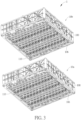
FIG. 1 is a perspective view illustrating a battery structure according to an embodiment of the invention, -
FIG. 2 is an exploded view illustrating the battery structure shown inFIG. 1 , -
FIG. 3 is an exploded view illustrating the battery structure shown inFIG. 1 from another viewing angle, -
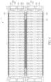
FIG. 4 is a sectional view illustrating the battery structure shown inFIG. 1 , -
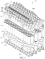
FIG. 5 is an exploded view illustrating the inside of a battery module shown inFIG. 2 , -
FIG. 6 is an enlarged view illustrating parts of the battery module shown inFIG. 2 , -
FIG. 7 is an enlarged view illustrating a first pad and a second pad shown inFIG. 5 , -
FIG. 8 is a perspective view illustrating a battery module according to another embodiment of the invention, and -
FIG. 9 is an enlarged view illustrating parts of the battery module shown inFIG. 8 . - As shown in
FIGs. 1 to 4 , thebattery structure 1 of the invention comprises twobattery modules battery modules battery structure 1 further comprises a conductiveelastic member 112 disposed between and in contact with a firstconductive plate 108 and a secondconductive plate 110 of the twobattery modules battery modules - Each of the two
battery modules housing 100, a plurality ofbattery cells 102, afirst holder 104, asecond holder 106, a firstconductive plate 108 and a secondconductive plate 110. Thebattery cells 102 are disposed in thehousing 100. Thefirst holder 104 accommodates an end of each of thebattery cells 102, and thesecond holder 106 accommodates another end of each of thebattery cells 102. In this embodiment, thefirst holder 104 may have a plurality of accommodatingholes 1040 for accommodating thebattery cells 102, and thesecond holder 106 may also have a plurality of accommodatingholes 1060 for accommodating thebattery cells 102. - The first
conductive plate 108 is disposed on thefirst holder 104 and electrically connected to thebattery cells 102. Similarly, the secondconductive plate 110 is disposed on thesecond holder 106 and electrically connected to thebattery cells 102. For further explanation, the firstconductive plate 108 may have a plurality offirst pads 1080 in contact with thebattery cells 102, and the secondconductive plate 110 may have a plurality ofsecond pads 1100 in contact with thebattery cells 102. Thefirst pads 1080 and thesecond pads 1100 may be soldered with the positive and negative terminals of thebattery cells 102. Furthermore, a shape of each of thefirst pads 1080 may be different from a shape of each of thesecond pads 1100, as shown inFIG. 7 . - In this embodiment, each of the
first pads 1080 is connected to the firstconductive plate 108 by at least one first connectingportion 1082, each of thesecond pads 1100 is connected to the secondconductive plate 110 by at least one second connectingportion 1102, and a total cross-sectional area of the at least one first connectingportion 1082 is smaller than a total cross-sectional area of the at least one second connectingportion 1102. For example, each of thefirst pads 1080 may consist of two semicircular structures connected to the firstconductive plate 108 by two first connectingportions 1082, and each of thesecond pads 1100 may be a spiral structure connected to the secondconductive plate 110 by twosecond connecting portions 1102. - In this case, the total cross-sectional area of the two first connecting
portions 1082 is smaller than the total cross-sectional area of the twosecond connecting portions 1102. Accordingly, when the current exceeds the design value, the two first connectingportions 1082 will be burned out first, thereby causing thecorresponding battery cell 102 to form an open circuit. Therefore, the invention can provide over-current protection function for each of thebattery cells 102. - It should be noted that the number of first
conductive plates 108 and secondconductive plates 110 may be determined according to practical applications. Furthermore, the firstconductive plate 108 may also have a plurality ofsecond pads 1100 and the secondconductive plate 110 may also have a plurality offirst pads 1080. Therefore, the invention may adjust the number of battery modules, firstconductive plates 108 and secondconductive plates 110, and adjust the series and parallel connection of battery cells by the arrangement offirst pads 1080 andsecond pads 1100, so as to adjust the voltage and capacity of the battery structure. - As shown in
FIGs. 2 ,5 and6 , thebattery module 10a further comprises the conductiveelastic member 112 disposed on the firstconductive plate 108. In this embodiment, the firstconductive plate 108 of thebattery module 10a may have twofirst restraining portions 1084, and the conductiveelastic member 112 may be restrained on the firstconductive plate 108 by the twofirst restraining portions 1084. For example, the conductiveelastic member 112 may be a coil spring with two ring-shaped ends 1120, and the two ring-shaped ends 1120 are hooked by the twofirst restraining portions 1084, so as to restrain the conductiveelastic member 112 on the firstconductive plate 108. The twofirst restraining portions 1084 may be bent from the firstconductive plate 108, but the invention is not so limited. - Furthermore, the
first holder 104 may have a plurality ofsecond restraining portions 1042 and the firstconductive plate 108 may further have a plurality of throughholes 1086. When the firstconductive plate 108 is disposed on thefirst holder 104, thesecond restraining portions 1042 pass through the throughholes 1086. Then, after the conductiveelastic member 112 is disposed on the firstconductive plate 108, thesecond restraining portions 1042 are located at opposite sides of the conductiveelastic member 112 in a radial direction of the conductiveelastic member 112. In this embodiment, thesecond restraining portions 1042 may be interlacedly located at the opposite sides of the conductiveelastic member 112. Thus, when thebattery module 10b is stacked on thebattery module 10a and compresses the conductiveelastic member 112, the conductiveelastic member 112 will deform elastically and thesecond restraining portions 1042 can restrain the position of the conductiveelastic member 112. In addition, the compression of the conductiveelastic member 112 may be adjusted by the height of thesecond restraining portions 1042. For example, the height of thesecond restraining portions 1042 may be smaller than half the height of the conductiveelastic member 112, but the invention is not so limited. Still further, thesecond restraining portions 1042 may extend to theaccommodating holes 1040 to restrain thebattery cells 102 in theaccommodating holes 1040. - Moreover, the
first holder 104 may have a plurality ofpositioning portions 1044 and the firstconductive plate 108 may further have a plurality of positioning holes 1088. When the firstconductive plate 108 is disposed on thefirst holder 104, thepositioning portions 1044 pass through thepositioning holes 1088 to position the firstconductive plate 108 on thefirst holder 104. In this embodiment, thepositioning portions 1044 may be made of plastic material, such that thepositioning portions 1044 may be melted to tightly fix the firstconductive plate 108 on thefirst holder 104. - Referring to
FIGs. 8 and9 , the main difference between thebattery module 10a' and theaforesaid battery module 10a is that the conductive elastic member 112' of thebattery module 10a' comprises an elastic structure 1122 and a conductive material 1124, wherein the elastic structure 1122 is covered with the conductive material 1124, as shown inFIGs. 8 and9 . The elastic structure 1122 may be made of rubber, sponge or other elastic materials, and the conductive material 1124 may be made of conductive metal. In this embodiment, the twofirst restraining portions 1084 of the firstconductive plate 108 may abut against two ends of the elastic structure 1122, so as to restrain the conductive elastic member 112' on the firstconductive plate 108. - The
battery module 10a shown inFIGs. 1 to 4 may be replaced by thebattery module 10a' shown inFIG. 8 . When thebattery module 10b is stacked on thebattery module 10a' and compresses the conductive elastic member 112', the conductive elastic member 112' will deform elastically and thesecond restraining portions 1042 can restrain the position of the conductive elastic member 112'. Thus, the conductive elastic member 112' is disposed between and in contact with the firstconductive plate 108 and the secondconductive plate 110 of the twobattery modules 10a', 10b, so as to achieve electrical connection between the twobattery modules 10a', 10b. - As mentioned in the above, the invention disposes the conductive elastic member between the two battery modules to achieve electrical connection. Accordingly, the two battery modules do not need to be assembled by additional components, such that the assembly process can be simplified to save time and the cost can be reduced. Furthermore, when the two battery modules are stacked with each other, the conductive elastic member will be compressed to deform elastically, such that the conductive elastic member will be in contact with the first conductive plate and the second conductive plate of the two battery modules tightly, so as to absorb assembly tolerance and ensure electrical connection between the two battery modules.
Claims (15)
- A battery structure (1) characterized by the battery structure (1) comprising:two battery modules (10a, 10a', 10b) stacked with each other, each of the two battery modules (10a, 10a', 10b) comprising:a housing (100);a plurality of battery cells (102) disposed in the housing (100);a first holder (104) accommodating an end of each of the plurality of battery cells (102);a second holder (106) accommodating another end of each of the plurality of battery cells (102);a first conductive plate (108) disposed on the first holder (104) and electrically connected to the plurality of battery cells (102); anda second conductive plate (110) disposed on the second holder (106) and electrically connected to the plurality of battery cells (102); anda conductive elastic member (112, 112') disposed between and in contact with the first conductive plate (108) and the second conductive plate (110) of the two battery modules (10a, 10a', 10b).
- The battery structure (1) of claim 1 further characterized in that the first conductive plate (108) of one of the two battery modules (10a, 10a') has two first restraining portions (1084), and the conductive elastic member (112, 112') is restrained on the first conductive plate (108) by the two first restraining portions (1084).
- The battery structure (1) of claim 2 further characterized in that the conductive elastic member (112) is a coil spring with two ring-shaped ends (1120), and the two ring-shaped ends (1120) are hooked by the two first restraining portions (1084).
- The battery structure (1) of claim 2 further characterized in that the conductive elastic member (112') comprises an elastic structure (1122) and a conductive material (1124), the elastic structure (1122) is covered with the conductive material (1124), and the two first restraining portions (1084) abut against two ends of the elastic structure (1122).
- The battery structure (1) of claim 1 further characterized in that the first holder (104) has a plurality of second restraining portions (1042), the first conductive plate (108) further has a plurality of through holes (1086), and the plurality of second restraining portions (1042) pass through the plurality of through holes (1086) and are located at opposite sides of the conductive elastic member (112, 112') in a radial direction of the conductive elastic member (112, 112').
- The battery structure (1) of claim 5 further characterized in that the first holder (104) further has a plurality of accommodating holes (1040) for accommodating the plurality of battery cells (102), and the plurality of second restraining portions (1042) extend to the plurality of accommodating holes (1040) to restrain the plurality of battery cells (102) in the plurality of accommodating holes (1040).
- The battery structure (1) of claim 1 further characterized in that the first holder (104) has a plurality of positioning portions (1044), the first conductive plate (108) further has a plurality of positioning holes (1088), and the plurality of positioning portions (1044) pass through the plurality of positioning holes (1088) to position the first conductive plate (108) on the first holder (104).
- The battery structure (1) of claim 1 further characterized in that the first conductive plate (108) has a plurality of first pads (1080) in contact with the plurality of battery cells (102), the second conductive plate (110) has a plurality of second pads (1100) in contact with the plurality of battery cells (102), a shape of each of the plurality of first pads (1080) is different from a shape of each of the plurality of second pads (1100), each of the plurality of first pads (1080) is connected to the first conductive plate (108) by at least one first connecting portion (1082), each of the plurality of second pads (1100) is connected to the second conductive plate (110) by at least one second connecting portion (1102), and a total cross-sectional area of the at least one first connecting portion (1082) is smaller than a total cross-sectional area of the at least one second connecting portion (1102).
- A battery module (10a, 10a') characterized by the battery module (10a, 10a') comprising:a housing (100);a plurality of battery cells (102) disposed in the housing (100);a first holder (104) accommodating an end of each of the plurality of battery cells (102);a second holder (106) accommodating another end of each of the plurality of battery cells (102);a first conductive plate (108) disposed on the first holder (104) and electrically connected to the plurality of battery cells (102), the first conductive plate (108) having two first restraining portions (1084);a second conductive plate (110) disposed on the second holder (106) and electrically connected to the plurality of battery cells (102); anda conductive elastic member (112, 112') restrained on the first conductive plate (108) by the two first restraining portions (1084).
- The battery module (10a) of claim 9 further characterized in that the conductive elastic member (112) is a coil spring with two ring-shaped ends (1120), and the two ring-shaped ends (1120) are hooked by the two first restraining portions (1084).
- The battery module (10a') of claim 9 further characterized in that the conductive elastic member (112') comprises an elastic structure (1122) and a conductive material (1124), the elastic structure (1122) is covered with the conductive material (1124), and the two first restraining portions (1084) abut against two ends of the elastic structure (1122).
- The battery module (10a, 10a') of claim 9 further characterized in that the first holder (104) has a plurality of second restraining portions (1042), the first conductive plate (108) further has a plurality of through holes (1086), and the plurality of second restraining portions (1042) pass through the plurality of through holes (1086) and are located at opposite sides of the conductive elastic member (112, 112') in a radial direction of the conductive elastic member (112, 112').
- The battery module (10a, 10a') of claim 12 further characterized in that the first holder (104) further has a plurality of accommodating holes (1040) for accommodating the plurality of battery cells (102), and the plurality of second restraining portions (1042) extend to the plurality of accommodating holes (1040) to restrain the plurality of battery cells (102) in the plurality of accommodating holes (1040).
- The battery module (10a, 10a') of claim 9 further characterized in that the first holder (104) has a plurality of positioning portions (1044), the first conductive plate (108) further has a plurality of positioning holes (1088), and the plurality of positioning portions (1044) pass through the plurality of positioning holes (1088) to position the first conductive plate (108) on the first holder (104).
- The battery module (10a, 10a') of claim 9 further characterized in that the first conductive plate (108) has a plurality of first pads (1080) in contact with the plurality of battery cells (102), the second conductive plate (110) has a plurality of second pads (1100) in contact with the plurality of battery cells (102), a shape of each of the plurality of first pads (1080) is different from a shape of each of the plurality of second pads (1100), each of the plurality of first pads (1080) is connected to the first conductive plate (108) by at least one first connecting portion (1082), each of the plurality of second pads (1100) is connected to the second conductive plate (110) by at least one second connecting portion (1102), and a total cross-sectional area of the at least one first connecting portion (1082) is smaller than a total cross-sectional area of the at least one second connecting portion (1102).
Applications Claiming Priority (1)
| Application Number | Priority Date | Filing Date | Title |
|---|---|---|---|
| US18/399,723 US20250219256A1 (en) | 2023-12-29 | 2023-12-29 | Battery structure and battery module |
Publications (2)
| Publication Number | Publication Date |
|---|---|
| EP4579901A1 true EP4579901A1 (en) | 2025-07-02 |
| EP4579901B1 EP4579901B1 (en) | 2026-04-15 |
Family
ID=94083100
Family Applications (1)
| Application Number | Title | Priority Date | Filing Date |
|---|---|---|---|
| EP24222339.4A Active EP4579901B1 (en) | 2023-12-29 | 2024-12-20 | Battery structure and battery module |
Country Status (4)
| Country | Link |
|---|---|
| US (1) | US20250219256A1 (en) |
| EP (1) | EP4579901B1 (en) |
| JP (1) | JP2025105372A (en) |
| TW (1) | TW202527362A (en) |
Citations (2)
| Publication number | Priority date | Publication date | Assignee | Title |
|---|---|---|---|---|
| US20170222207A1 (en) * | 2016-02-03 | 2017-08-03 | Boston-Power, Inc. | Battery Cell Connector, Interconnect Board And Battery Block System |
| EP3428994A1 (en) * | 2017-07-11 | 2019-01-16 | BMZ GmbH | Device for holding electrically conductively connected components, use and method for producing a device for holding electrically conductively connected components |
Family Cites Families (3)
| Publication number | Priority date | Publication date | Assignee | Title |
|---|---|---|---|---|
| CN100429812C (en) * | 2003-12-05 | 2008-10-29 | 日产自动车株式会社 | Positive electrode material for non-aqueous electrolyte lithium ion battery and battery using the same |
| JP2019079726A (en) * | 2017-10-25 | 2019-05-23 | 株式会社ケーヒン | Voltage detection device |
| JP7593959B2 (en) * | 2022-02-04 | 2024-12-03 | プライムプラネットエナジー&ソリューションズ株式会社 | Battery pack |
-
2023
- 2023-12-29 US US18/399,723 patent/US20250219256A1/en active Pending
-
2024
- 2024-02-16 JP JP2024022386A patent/JP2025105372A/en active Pending
- 2024-12-03 TW TW113146687A patent/TW202527362A/en unknown
- 2024-12-20 EP EP24222339.4A patent/EP4579901B1/en active Active
Patent Citations (2)
| Publication number | Priority date | Publication date | Assignee | Title |
|---|---|---|---|---|
| US20170222207A1 (en) * | 2016-02-03 | 2017-08-03 | Boston-Power, Inc. | Battery Cell Connector, Interconnect Board And Battery Block System |
| EP3428994A1 (en) * | 2017-07-11 | 2019-01-16 | BMZ GmbH | Device for holding electrically conductively connected components, use and method for producing a device for holding electrically conductively connected components |
Also Published As
| Publication number | Publication date |
|---|---|
| US20250219256A1 (en) | 2025-07-03 |
| JP2025105372A (en) | 2025-07-10 |
| TW202527362A (en) | 2025-07-01 |
| EP4579901B1 (en) | 2026-04-15 |
Similar Documents
| Publication | Publication Date | Title |
|---|---|---|
| EP2381506B1 (en) | Battery module | |
| US5096788A (en) | Weldless battery pack | |
| US9887410B2 (en) | Flexible fusible link, systems, and methods | |
| CN1305143C (en) | Battery group | |
| US7609028B2 (en) | Sensing board assembly for secondary battery module | |
| EP2590242B1 (en) | Method and device for improving the performance of battery module by leveling voltage | |
| CN110073520B (en) | Battery module and battery pack including the same | |
| CN117219942A (en) | Battery modules and battery packs and vehicles including the battery modules | |
| EP3582286B1 (en) | Battery cell frame and battery module comprising same | |
| KR20070043537A (en) | Battery pack with no welding | |
| CN114730968B (en) | Battery module provided with track-type socket and battery pack including the battery module | |
| EP4579901A1 (en) | Battery structure and battery module | |
| KR20130012469A (en) | Energy storage module | |
| KR101826862B1 (en) | Battery Pack Having Protection Module | |
| KR20220047057A (en) | Battery module and battery pack including the same and vehicle including the same | |
| KR101039518B1 (en) | Battery cell connection member | |
| KR102714029B1 (en) | Battery module and battery pack including the same and vehicle including the same | |
| KR102887129B1 (en) | Battery module, battery pack and vehicle comprising the same | |
| KR102618035B1 (en) | Battery pack | |
| KR100973422B1 (en) | Compact secondary battery pack | |
| CN115516714B (en) | Battery pack including components that can prevent undesirable contact with the device. | |
| CN121444266A (en) | Battery pack and vehicle including the battery pack | |
| KR100993128B1 (en) | Electrical contact member of physical contact method and battery pack including the same |
Legal Events
| Date | Code | Title | Description |
|---|---|---|---|
| PUAI | Public reference made under article 153(3) epc to a published international application that has entered the european phase |
Free format text: ORIGINAL CODE: 0009012 |
|
| STAA | Information on the status of an ep patent application or granted ep patent |
Free format text: STATUS: THE APPLICATION HAS BEEN PUBLISHED |
|
| AK | Designated contracting states |
Kind code of ref document: A1 Designated state(s): AL AT BE BG CH CY CZ DE DK EE ES FI FR GB GR HR HU IE IS IT LI LT LU LV MC ME MK MT NL NO PL PT RO RS SE SI SK SM TR |
|
| STAA | Information on the status of an ep patent application or granted ep patent |
Free format text: STATUS: REQUEST FOR EXAMINATION WAS MADE |
|
| 17P | Request for examination filed |
Effective date: 20250824 |
|
| GRAP | Despatch of communication of intention to grant a patent |
Free format text: ORIGINAL CODE: EPIDOSNIGR1 |
|
| STAA | Information on the status of an ep patent application or granted ep patent |
Free format text: STATUS: GRANT OF PATENT IS INTENDED |
|
| RIC1 | Information provided on ipc code assigned before grant |
Ipc: H01M 50/152 20210101AFI20251027BHEP Ipc: H01M 50/213 20210101ALI20251027BHEP Ipc: H01M 50/284 20210101ALI20251027BHEP Ipc: H01M 50/287 20210101ALI20251027BHEP Ipc: H01M 50/289 20210101ALI20251027BHEP Ipc: H01M 50/503 20210101ALI20251027BHEP Ipc: H01M 50/514 20210101ALI20251027BHEP |
|
| INTG | Intention to grant announced |
Effective date: 20251106 |
|
| GRAS | Grant fee paid |
Free format text: ORIGINAL CODE: EPIDOSNIGR3 |
|
| GRAA | (expected) grant |
Free format text: ORIGINAL CODE: 0009210 |
|
| STAA | Information on the status of an ep patent application or granted ep patent |
Free format text: STATUS: THE PATENT HAS BEEN GRANTED |
|
| AK | Designated contracting states |
Kind code of ref document: B1 Designated state(s): AL AT BE BG CH CY CZ DE DK EE ES FI FR GB GR HR HU IE IS IT LI LT LU LV MC ME MK MT NL NO PL PT RO RS SE SI SK SM TR |
|
| REG | Reference to a national code |
Ref country code: CH Ref legal event code: F10 Free format text: ST27 STATUS EVENT CODE: U-0-0-F10-F00 (AS PROVIDED BY THE NATIONAL OFFICE) Effective date: 20260415 |