EP4579884A1 - Battery pack and powered device - Google Patents
Battery pack and powered device Download PDFInfo
- Publication number
- EP4579884A1 EP4579884A1 EP24193314.2A EP24193314A EP4579884A1 EP 4579884 A1 EP4579884 A1 EP 4579884A1 EP 24193314 A EP24193314 A EP 24193314A EP 4579884 A1 EP4579884 A1 EP 4579884A1
- Authority
- EP
- European Patent Office
- Prior art keywords
- disposed
- liquid
- battery pack
- box
- liquid outlet
- Prior art date
- Legal status (The legal status is an assumption and is not a legal conclusion. Google has not performed a legal analysis and makes no representation as to the accuracy of the status listed.)
- Pending
Links
Images


Classifications
-
- H—ELECTRICITY
- H01—ELECTRIC ELEMENTS
- H01M—PROCESSES OR MEANS, e.g. BATTERIES, FOR THE DIRECT CONVERSION OF CHEMICAL ENERGY INTO ELECTRICAL ENERGY
- H01M10/00—Secondary cells; Manufacture thereof
- H01M10/60—Heating or cooling; Temperature control
- H01M10/65—Means for temperature control structurally associated with the cells
- H01M10/655—Solid structures for heat exchange or heat conduction
- H01M10/6556—Solid parts with flow channel passages or pipes for heat exchange
- H01M10/6557—Solid parts with flow channel passages or pipes for heat exchange arranged between the cells
-
- H—ELECTRICITY
- H01—ELECTRIC ELEMENTS
- H01M—PROCESSES OR MEANS, e.g. BATTERIES, FOR THE DIRECT CONVERSION OF CHEMICAL ENERGY INTO ELECTRICAL ENERGY
- H01M10/00—Secondary cells; Manufacture thereof
- H01M10/60—Heating or cooling; Temperature control
- H01M10/65—Means for temperature control structurally associated with the cells
- H01M10/655—Solid structures for heat exchange or heat conduction
- H01M10/6556—Solid parts with flow channel passages or pipes for heat exchange
-
- H—ELECTRICITY
- H01—ELECTRIC ELEMENTS
- H01M—PROCESSES OR MEANS, e.g. BATTERIES, FOR THE DIRECT CONVERSION OF CHEMICAL ENERGY INTO ELECTRICAL ENERGY
- H01M10/00—Secondary cells; Manufacture thereof
- H01M10/60—Heating or cooling; Temperature control
- H01M10/65—Means for temperature control structurally associated with the cells
- H01M10/656—Means for temperature control structurally associated with the cells characterised by the type of heat-exchange fluid
- H01M10/6567—Liquids
- H01M10/6568—Liquids characterised by flow circuits, e.g. loops, located externally to the cells or cell casings
-
- H—ELECTRICITY
- H01—ELECTRIC ELEMENTS
- H01M—PROCESSES OR MEANS, e.g. BATTERIES, FOR THE DIRECT CONVERSION OF CHEMICAL ENERGY INTO ELECTRICAL ENERGY
- H01M10/00—Secondary cells; Manufacture thereof
- H01M10/60—Heating or cooling; Temperature control
- H01M10/61—Types of temperature control
- H01M10/613—Cooling or keeping cold
-
- H—ELECTRICITY
- H01—ELECTRIC ELEMENTS
- H01M—PROCESSES OR MEANS, e.g. BATTERIES, FOR THE DIRECT CONVERSION OF CHEMICAL ENERGY INTO ELECTRICAL ENERGY
- H01M10/00—Secondary cells; Manufacture thereof
- H01M10/60—Heating or cooling; Temperature control
- H01M10/62—Heating or cooling; Temperature control specially adapted for specific applications
- H01M10/625—Vehicles
-
- H—ELECTRICITY
- H01—ELECTRIC ELEMENTS
- H01M—PROCESSES OR MEANS, e.g. BATTERIES, FOR THE DIRECT CONVERSION OF CHEMICAL ENERGY INTO ELECTRICAL ENERGY
- H01M10/00—Secondary cells; Manufacture thereof
- H01M10/60—Heating or cooling; Temperature control
- H01M10/64—Heating or cooling; Temperature control characterised by the shape of the cells
- H01M10/647—Prismatic or flat cells, e.g. pouch cells
-
- H—ELECTRICITY
- H01—ELECTRIC ELEMENTS
- H01M—PROCESSES OR MEANS, e.g. BATTERIES, FOR THE DIRECT CONVERSION OF CHEMICAL ENERGY INTO ELECTRICAL ENERGY
- H01M2220/00—Batteries for particular applications
- H01M2220/20—Batteries in motive systems, e.g. vehicle, ship, plane
-
- Y—GENERAL TAGGING OF NEW TECHNOLOGICAL DEVELOPMENTS; GENERAL TAGGING OF CROSS-SECTIONAL TECHNOLOGIES SPANNING OVER SEVERAL SECTIONS OF THE IPC; TECHNICAL SUBJECTS COVERED BY FORMER USPC CROSS-REFERENCE ART COLLECTIONS [XRACs] AND DIGESTS
- Y02—TECHNOLOGIES OR APPLICATIONS FOR MITIGATION OR ADAPTATION AGAINST CLIMATE CHANGE
- Y02E—REDUCTION OF GREENHOUSE GAS [GHG] EMISSIONS, RELATED TO ENERGY GENERATION, TRANSMISSION OR DISTRIBUTION
- Y02E60/00—Enabling technologies; Technologies with a potential or indirect contribution to GHG emissions mitigation
- Y02E60/10—Energy storage using batteries
Definitions
- the present invention relates to the technical field of batteries, in particular, a battery pack and a powered device.
- One purpose of the present invention is to provide a battery pack. With this battery pack, the problem of internal leakage of the battery pack is effectively solved, a short circuit is not likely to occur, and the safety is relatively high.
- Another purpose of the present invention is to provide a powered device. With the configuration of the preceding battery pack, high safety performance is provided.
- a battery pack is provided.
- the battery pack includes a box, a cell, a liquid cooling plate attached to the cell, a liquid inlet pipe, and a liquid outlet pipe.
- a bottom guard plate is disposed at the bottom of the box.
- the cell and the liquid cooling plate are both disposed in the box.
- a liquid inlet nozzle and a liquid outlet nozzle are disposed in the liquid cooling plate and penetrate through the bottom guard plate to outside the box.
- the liquid inlet pipe and the liquid outlet pipe are disposed outside the box.
- the liquid inlet pipe is provided with a first quick connector.
- the liquid outlet pipe is provided with a second quick connector.
- the first quick connector is connected to the liquid inlet nozzle.
- the second quick connector is connected to the liquid outlet nozzle.
- the liquid cooling plate includes a body and a collector.
- the collector is connected to an end of the body.
- the liquid inlet nozzle and the liquid outlet nozzle are disposed on the collector and separately communicate with the flow channel.
- the liquid cooling plate includes two collectors. Two ends of the body in the length direction are a first end and a second end, respectively. The two collectors are disposed at the first end and the second end, respectively. The liquid inlet nozzle is disposed on a collector at the first end. The liquid outlet nozzle is disposed on the other collector at the second end.
- the battery pack includes a plurality of cells and a plurality of liquid cooling plates.
- the plurality of cells and the plurality of liquid cooling plates are arranged alternately in the length direction of the body to form a battery module.
- a liquid cooling plate is bonded to a large surface of a respective cell.
- a thermally conductive adhesive is disposed between the liquid cooling plate and the large surface of the respective cell.
- a second structural adhesive is filled between each bottom at two sides of the box in the width direction of the box and a bottom at a respective side of the battery module.
- a bracket is fixed to the inner side of the bottom guard plate, a support plate is disposed on the bracket and configured to support the cell, and a first structural adhesive is disposed between the support plate and the bottom of the cell.
- a protective cover is disposed on the bottom side of the bottom guard plate and is disposed to cover the outside of the liquid inlet pipe and the liquid outlet pipe.
- the liquid inlet pipe 30 is provided with a first quick connector 31, the liquid outlet pipe 40 is provided with a second quick connector 41, the first quick connector 31 is connected to the liquid inlet nozzle 223, and the second quick connector 41 is connected to the liquid outlet nozzle 224.
- the liquid inlet pipe 30, the first quick connector 31, the liquid inlet nozzle 223, the liquid cooling plate 22, the liquid outlet nozzle 224, the second quick connector 41, and the liquid outlet pipe 40 are connected in sequence.
- coolant in the cooling device flows into the liquid cooling plate 22 through the liquid inlet pipe 30, the first quick connector 31, and the liquid inlet nozzle 223, dissipates heat from the cell 21 by heat exchange, and discharges heat as the coolant flows.
- the discharged coolant flows into the liquid outlet pipe 40 through the liquid outlet nozzle 224 and the second quick connector 41 and finally flows back to the cooling device.
- a liquid cooling circuit is formed to reduce the temperature of the cell 21. The cooling effect is good.
- each bracket 13 extends in the X-axis direction, and the multiple brackets 13 are arranged at intervals in the Y-axis direction.
- a support plate 14 is disposed on the bracket 13 to support the cell 21. This arrangement can improve the structural strength of the bottom of the box 10, thereby stably supporting the battery module 20.
- a first structural adhesive 15 is disposed between the support plate 14 and the bottom of the cell 21 and used to bond and fix the bottom of the cell 21 to the support plate 14 to ensure a stable connection between the two.
- a second structural adhesive 16 is filled between each bottom at two sides of the box 10 in the width direction of the box 10 and a bottom at a respective side of the battery module 20.
- the second structural adhesive 16 is configured to adhere two sides of the battery module 20 respectively to the two inner sides of the box 10 to ensure a stable connection.
- the second structural adhesive 16 can provide sealing separately between the liquid inlet nozzle 223 and the bottom guard plate 11 and between the liquid outlet nozzle 224 and the bottom guard plate 11 to achieve waterproofing.
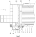
- FIG. 7 only shows the structure of one side of the box 10 and the battery module 20, and the structure of the other side is the same as the one side.
Landscapes
- Engineering & Computer Science (AREA)
- Manufacturing & Machinery (AREA)
- Chemical & Material Sciences (AREA)
- Chemical Kinetics & Catalysis (AREA)
- Electrochemistry (AREA)
- General Chemical & Material Sciences (AREA)
- Secondary Cells (AREA)
- Battery Mounting, Suspending (AREA)
Abstract
Description
- The present invention relates to the technical field of batteries, in particular, a battery pack and a powered device.
- As the main energy form of new energy vehicles, the performance of a battery pack directly affects the overall performance of a new energy vehicle. Currently, battery packs on the market generally use liquid cooling systems for heat dissipation. For a liquid cooling system with multiple liquid cooling plates, nylon pipes are usually used to connect these liquid cooling plates, and then pipes with quick connectors are used to connect the liquid cooling plates and water nozzles on the box to guide the coolant from the liquid cooling plates to the outside of the battery pack.
- This design is prone to the following problems: There are a large number of pipes and quick connectors. A car is used in a vibration environment for a long time, and quick connectors or pipes are prone to loosening and poor contact, or a sealing ring inside the car fails, resulting in leakage. The leaked coolant may flow everywhere inside the battery pack, which may cause a short circuit in the battery pack, and even fire, or other unpredictable dangers.
- Therefore, it is urgent to provide a battery pack and a powered device to resolve the preceding problems.
- One purpose of the present invention is to provide a battery pack. With this battery pack, the problem of internal leakage of the battery pack is effectively solved, a short circuit is not likely to occur, and the safety is relatively high.
- Another purpose of the present invention is to provide a powered device. With the configuration of the preceding battery pack, high safety performance is provided.
- To achieve the preceding purposes, the present invention is implemented by the following technical solutions:
A battery pack is provided. - The battery pack includes a box, a cell, a liquid cooling plate attached to the cell, a liquid inlet pipe, and a liquid outlet pipe. A bottom guard plate is disposed at the bottom of the box.
- The cell and the liquid cooling plate are both disposed in the box. A liquid inlet nozzle and a liquid outlet nozzle are disposed in the liquid cooling plate and penetrate through the bottom guard plate to outside the box.
- The liquid inlet pipe and the liquid outlet pipe are disposed outside the box. The liquid inlet pipe is provided with a first quick connector. The liquid outlet pipe is provided with a second quick connector. The first quick connector is connected to the liquid inlet nozzle. The second quick connector is connected to the liquid outlet nozzle.
- As an optional solution, the liquid cooling plate includes a body and a collector.
- The body is provided with a flow channel extending in the length direction and disposed inside the body.
- The collector is connected to an end of the body. The liquid inlet nozzle and the liquid outlet nozzle are disposed on the collector and separately communicate with the flow channel.
- As an optional solution, the liquid cooling plate includes two collectors. Two ends of the body in the length direction are a first end and a second end, respectively. The two collectors are disposed at the first end and the second end, respectively. The liquid inlet nozzle is disposed on a collector at the first end. The liquid outlet nozzle is disposed on the other collector at the second end.
- As an optional solution, the battery pack includes a plurality of cells and a plurality of liquid cooling plates. The plurality of cells and the plurality of liquid cooling plates are arranged alternately in the length direction of the body to form a battery module. A liquid cooling plate is bonded to a large surface of a respective cell.
- As an optional solution, a thermally conductive adhesive is disposed between the liquid cooling plate and the large surface of the respective cell.
- As an optional solution, a second structural adhesive is filled between each bottom at two sides of the box in the width direction of the box and a bottom at a respective side of the battery module.
- As an optional solution, foam is attached to the inner side of the bottom guard plate, and around the liquid inlet nozzle and the liquid outlet nozzle.
- As an optional solution, a bracket is fixed to the inner side of the bottom guard plate, a support plate is disposed on the bracket and configured to support the cell, and a first structural adhesive is disposed between the support plate and the bottom of the cell.
- As an optional solution, a protective cover is disposed on the bottom side of the bottom guard plate and is disposed to cover the outside of the liquid inlet pipe and the liquid outlet pipe.
- A powered device includes the preceding battery pack.
- The present invention has the beneficial effects described below.
- In the battery pack provided by the present invention, the coolant flows into the liquid cooling plate through the first quick connector and the liquid inlet nozzle to cool the cell, and the heated coolant flows out from the liquid outlet nozzle and the second quick connector to the liquid outlet pipe to complete cooling of the cell. In this battery pack, the liquid inlet nozzle, the liquid inlet pipe, the liquid outlet nozzle, and the liquid outlet pipe are all located at the bottom of the box. Thus, a design without a pipe connection and a quick connector in the battery pack can be implemented. Leakage of quick connectors, if occurs, only happens outside the battery pack, thus avoiding leakage inside the battery pack and damage to the battery pack and improving the service life and safety of the battery pack. Secondly, since quick connectors are located at the bottom of the battery pack, when a certain quick connector fails due to leakage, the quick connector can be quickly replaced outside the battery pack without disassembling the entire battery pack. In this manner, after-sales costs are reduced.
- The powered device provided by the present invention has high safety performance through the configuration of the preceding battery pack.
- To illustrate the embodiments of the present invention or the technical solutions in the related art more clearly and easily, the drawings used in the description of the embodiments or of the related art will be briefly described below. The drawings described below are merely part of the embodiments of the present invention, and those of ordinary skill in the art may acquire other drawings based on the drawings described below on the premise that no creative work is done.
-
FIG. 1 is a view illustrating the front structure of a battery pack according to an embodiment of the present invention. -
FIG. 2 is a view illustrating the structure of a battery module according to an embodiment of the present invention. -
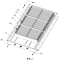
FIG. 3 is a sectional view of a liquid cooling plate according to an embodiment of the present invention. -
FIG. 4 is a view one illustrating the back structure of a battery pack according to an embodiment of the present invention. -
FIG. 5 is a view illustrating the structure of a box according to an embodiment of the present invention. -
FIG. 6 is a view two illustrating the back structure of a battery pack according to an embodiment of the present invention. -
FIG. 7 is a partial sectional view of a battery pack according to an embodiment of the present invention. -
- 10
- box
- 11
- bottom guard plate
- 12
- beam
- 13
- bracket
- 14
- support plate
- 15
- first structural adhesive
- 16
- second structural adhesive
- 17
- foam
- 20
- battery module
- 21
- cell
- 22
- liquid cooling plate
- 221
- body
- 222
- collector
- 223
- liquid inlet nozzle
- 224
- liquid outlet nozzle
- 225
- flow channel
- 30
- liquid inlet pipe
- 31
- first quick connector
- 40
- liquid outlet pipe
- 41
- second quick connector
- 50
- protective cover
- The present invention is further described below in detail in conjunction with drawings and embodiments. It is to be understood that the embodiments set forth below are intended to merely illustrate and not to limit the present invention. It should also be noted that for ease of description, only a part related to the present unity model rather than the entire structure is illustrated in the drawings.
- In the description of the present invention, terms "connected to each other", "connected", or "secured" are to be construed in a broad sense unless otherwise expressly specified and limited, for example, as securely connected, detachably connected, or integrated; mechanically connected or electrically connected; directly connected to each other or indirectly connected to each other via an intermediary; or internally connected between two elements or interaction relations between two elements. For those of ordinary skill in the art, specific meanings of the preceding terms in the present invention may be understood based on specific situations.
- In the present invention, unless otherwise expressly specified and limited, when a first feature is described as "on" or "below" a second feature, the first feature and the second feature may be in direct contact or be in contact via another feature between the two features instead of being in direct contact. Moreover, when the first feature is "on", "above", or "over" the second feature, the first feature is right on, above, or over the second feature, or the first feature is obliquely on, above, or over the second feature, or the first feature is simply at a higher level than the second feature. When the first feature is "under", "below", or "underneath" the second feature, the first feature is right under, below, or underneath the second feature, or the first feature is obliquely under, below, or underneath the second feature, or the first feature is simply at a lower level than the second feature.
- In the description of the embodiments, it is to be noted that orientations or position relations indicated by terms such as "above", "below", "left" and "right" are based on the drawings. These orientations or position relations are intended only to facilitate the description and simplify an operation and not to indicate or imply that a device or element referred to reruired have such particular orientations or must be configured or operated in such particular orientations. Thus, these orientations or position relations are not to be construed as limiting the present invention. In addition, terms "first" and "second" are used only to distinguish between descriptions and have no special meaning.
- As shown in
FIG. 1 to FIG. 4 , the embodiment provides a battery pack including abox 10, abattery module 20, aliquid inlet pipe 30, and aliquid outlet pipe 40; abottom guard plate 11 is disposed at the bottom of thebox 10; thebattery module 20 is disposed in thebox 10; thebattery module 20 includes acell 21 and aliquid cooling plate 22 attached to thecell 21; theliquid cooling plate 22 is provided with aliquid inlet nozzle 223 and aliquid outlet nozzle 224 penetrating through thebottom guard plate 11 to the outside of thebox 10; thebottom guard plate 11 is provided with a through hole for theliquid inlet nozzle 223 and theliquid outlet nozzle 224 to pass through; theliquid inlet pipe 30 and theliquid outlet pipe 40 are disposed outside thebox 10, theliquid inlet pipe 30 is connected to the output end of a cooling device, and theliquid outlet pipe 40 is connected to the input end of the cooling device. Theliquid inlet pipe 30 is provided with a firstquick connector 31, theliquid outlet pipe 40 is provided with a secondquick connector 41, the firstquick connector 31 is connected to theliquid inlet nozzle 223, and the secondquick connector 41 is connected to theliquid outlet nozzle 224. Theliquid inlet pipe 30, the firstquick connector 31, theliquid inlet nozzle 223, theliquid cooling plate 22, theliquid outlet nozzle 224, the secondquick connector 41, and theliquid outlet pipe 40 are connected in sequence. - During operation, coolant in the cooling device flows into the
liquid cooling plate 22 through theliquid inlet pipe 30, the firstquick connector 31, and theliquid inlet nozzle 223, dissipates heat from thecell 21 by heat exchange, and discharges heat as the coolant flows. The discharged coolant flows into theliquid outlet pipe 40 through theliquid outlet nozzle 224 and the secondquick connector 41 and finally flows back to the cooling device. Thus, a liquid cooling circuit is formed to reduce the temperature of thecell 21. The cooling effect is good. - In the battery pack, the
liquid inlet nozzle 223, the firstquick connector 31, theliquid inlet pipe 30, theliquid outlet nozzle 224, the secondquick connector 41, and theliquid outlet pipe 40 are all located at the bottom of thebox 10. Thus, a design without a pipe connection and a quick connector inside the battery pack can be implemented. Leakage of quick connectors, if occurs, only happens outside the battery pack, thus avoiding leakage inside the battery pack and damage to the battery pack and improving the service life and safety of the battery pack. Secondly, since quick connectors are located at the bottom of the battery pack, when a quick connector fails due to leakage, the quick connector can be quickly replaced outside the battery pack without disassembling the entire battery pack. In this manner, after-sales costs are reduced. - With reference to
FIG. 1 , one ormore battery modules 20 may be provided. Whenmultiple battery modules 20 are provided, themultiple battery modules 20 may be arranged in the X-axis direction. The X-axis direction is the length direction of thebox 10. The Y-axis direction is the width direction of thebox 10. As shown inFIG. 5 ,multiple beams 12 are also disposed in thebox 10; eachbeam 12 is parallel to the Y-axis, and themultiple beams 12 are arranged at intervals in the X-axis direction. Thebeams 12 divide the space in thebox 10 into multiple subspaces, and each subspace contains abattery module 20. When abattery module 20 in a certain subspace misfires due to high temperature, thebeams 12 can separate the subspace where thebattery module 20 misfires due to high temperature frombattery modules 20 in other subspaces, thereby reducing losses. - Specifically, with reference to
FIG. 1 andFIG. 2 , eachbattery module 20 includesmultiple cells 21 and multipleliquid cooling plates 22. Thecells 21 and theliquid cooling plates 22 are arranged alternately in the X-axis direction, that is, oneliquid cooling plate 22 is arranged between any twoadjacent cells 21, and two sides of aliquid cooling plate 22 are attached to thecells 21 on the adjacent two sides, respectively. In this manner, the cooling effect is improved, and thebattery module 20 has better temperature uniformity. Aliquid inlet nozzle 223 and aliquid outlet nozzle 224 are disposed on eachliquid cooling plate 22. Correspondingly, multiple firstquick connectors 31 are disposed on theliquid inlet pipe 30 and are in a one-to-one correspondence withliquid inlet nozzles 223, multiple secondquick connectors 41 are disposed on theliquid outlet pipe 40 and are in a one-to-one correspondence withliquid outlet nozzles 224, and multiple through holes are disposed on thebottom guard plate 11 for the correspondingliquid inlet nozzles 223 andliquid outlet nozzles 224 to pass through. - In this embodiment, the
cell 21 is square, and theliquid cooling plate 22 is configured as a flat plate structure. Theliquid cooling plate 22 is bonded to a large surface of thecell 21 to increase the contact area between theliquid cooling plate 22 and eachcell 21, thereby playing a good cooling effect on thecell 21 and improving the heat dissipation effect. - Preferably, a thermally conductive adhesive is disposed between the
liquid cooling plate 22 and the large surface of thecell 21. On the one hand, the thermally conductive adhesive reduces the contact thermal resistance between theliquid cooling plate 22 and thecell 21. The heat conduction effect is better. On the other hand, the thermally conductive adhesive can bond thecell 21 and the correspondingliquid cooling plate 22 into a group. The structure is stable and reliable. - Specifically, as shown in
FIG. 3 , theliquid cooling plate 22 includes abody 221 and acollector 222, and thebody 221 is provided with aflow channel 225 extending in the length direction and disposed inside thebody 21. Thecollector 222 is connected to an end of thebody 221, and theliquid inlet nozzle 223 and theliquid outlet nozzle 224 are disposed on thecollector 222 and separately communicate with theflow channel 225. The coolant enters theflow channel 225 of theliquid cooling plate 22 through theliquid inlet nozzle 223 to cool thecell 21. Then the coolant transfers the heat by flowing along theflow channel 225 and is discharged through theliquid outlet nozzle 224 to complete the cooling of thecell 21. Preferably, theflow channel 225 includes multiple sub-flow channels arranged in parallel in the height direction of theflow channel 225 so that thecell 21 has better temperature uniformity. - Preferably, as shown in
FIG. 3 , theliquid cooling plate 22 includes twocollectors 222, two ends of thebody 221 in the length direction (Y-axis direction) are a first end and a second end, respectively, the twocollectors 222 are disposed at the first end and the second end, respectively, theliquid inlet nozzle 223 is disposed on thecollector 222 at the first end, and theliquid outlet nozzle 224 is disposed on thecollector 222 at the second end. That is, theliquid inlet nozzle 223 and theliquid outlet nozzle 224 are disposed at two ends of theliquid cooling plate 22 respectively in the Y-axis direction. Allliquid inlet nozzles 223 in thebattery module 20 are located at the first end, and allliquid outlet nozzles 224 are located at the second end. On the back of thebottom guard plate 11 of thebox 10, as shown inFIG. 4 , theliquid inlet pipe 30 and theliquid outlet pipe 40 are disposed on two sides of thebottom guard plate 11 in the Y-axis direction respectively; all firstquick connectors 31 are disposed on the same side, and all secondquick connectors 41 are disposed on the other side. This arrangement can optimize the layout of the liquid cooling pipe, avoid clutter caused by excessive concentration of pipelines, and facilitate users to manage and monitor the cooling pipelines. - As shown in
FIG. 6 , aprotective cover 50 is disposed on the bottom side of thebottom guard plate 11, and theprotective cover 50 is disposed to cover the outside of theliquid inlet pipe 30 and theliquid outlet pipe 40 and is fixedly connected to the bottom of thebox 10. Since theliquid inlet pipe 30 and theliquid outlet pipe 40 are arranged on the two sides, twoprotective covers 50 are provided. Oneprotective layer 50 is disposed to cover the outside of theliquid inlet pipe 30, and the other is disposed to cover the outside of theliquid outlet pipe 40. With the configuration of theprotective cover 50, theliquid inlet nozzle 223, theliquid outlet nozzle 224, the firstquick connector 31, the secondquick connector 41, and the corresponding pipelines that are outside thebox 10 can be protected to prevent damage when subjected to external force impact. In addition, when a quick connector fails due to leakage, the quick connector can be replaced by removing theprotective cover 50 at the bottom of the battery pack, without disassembling the battery pack. Thus, management and maintenance are facilitated. - Further, as shown in
FIG. 5 andFIG. 7 ,multiple brackets 13 are fixed to the inner side of thebottom guard plate 11, eachbracket 13 extends in the X-axis direction, and themultiple brackets 13 are arranged at intervals in the Y-axis direction. Asupport plate 14 is disposed on thebracket 13 to support thecell 21. This arrangement can improve the structural strength of the bottom of thebox 10, thereby stably supporting thebattery module 20. A firststructural adhesive 15 is disposed between thesupport plate 14 and the bottom of thecell 21 and used to bond and fix the bottom of thecell 21 to thesupport plate 14 to ensure a stable connection between the two. - As shown in
FIG. 7 , a secondstructural adhesive 16 is filled between each bottom at two sides of thebox 10 in the width direction of thebox 10 and a bottom at a respective side of thebattery module 20. The secondstructural adhesive 16 is configured to adhere two sides of thebattery module 20 respectively to the two inner sides of thebox 10 to ensure a stable connection. In addition, the secondstructural adhesive 16 can provide sealing separately between theliquid inlet nozzle 223 and thebottom guard plate 11 and between theliquid outlet nozzle 224 and thebottom guard plate 11 to achieve waterproofing. It should be noted thatFIG. 7 only shows the structure of one side of thebox 10 and thebattery module 20, and the structure of the other side is the same as the one side. - As shown in
FIG. 5 andFIG. 7 ,foam 17 is attached to the inner side of thebottom guard plate 11, and hole positions on thefoam 17 are arranged to correspond to the through holes on thebottom guard plate 11. After theliquid inlet nozzle 223 and theliquid outlet nozzle 224 penetrate through the corresponding through holes, thefoam 17 on two sides is disposed around theliquid inlet nozzle 223 and theliquid outlet nozzle 224. By the configuration of thefoam 17, it is possible to prevent the adhesive from leaking from the through holes of thebottom guard plate 11 when the secondstructural adhesive 16 is poured in. - The specific assembly process of the battery pack is as follows. First, the
liquid cooling plate 22 and thecell 21 are bonded by the thermally conductive adhesive to form abattery module 20. Then, corresponding through holes are opened on thebottom guard plate 11 according to the positions of theliquid inlet nozzle 223 and theliquid outlet nozzle 224, and thefoam 17 is attached to thebottom guard plate 11. After that, the firststructural adhesive 15 is applied to thesupport plate 14, thebattery module 20 is placed on thesupport plate 14, and theliquid inlet nozzle 223 and theliquid outlet nozzle 224 of theliquid cooling plate 22 pass downward through the through holes of thebottom guard plate 11 to penetrate through thebottom guard plate 11 to the outside of thebox 10. Then, the secondstructural adhesive 16 is poured into the two inner sides of thebox 10 to adhere thebattery module 20 to the side of thebox 10. After that, each firstquick connector 31 on theliquid inlet pipe 30 is connected to a correspondingliquid inlet nozzle 223, and each secondquick connector 41 on theliquid outlet pipe 40 is connected to a correspondingliquid outlet nozzle 224 to form a liquid cooling circuit. Finally, theprotective cover 50 is fixed to the bottom surface of thebottom guard plate 11. - This embodiment also provides a powered device including the preceding battery pack. The battery pack can supply power for the powered device. The powered device may be an electric vehicle, a hybrid electric vehicle, a ship, or the like. In some embodiments, the powered device is an electric vehicle. The electric vehicle is a battery electric vehicle, a hybrid electric vehicle, or an extended-range vehicle. In other embodiments, the powered device may also be other devices, which are not specifically limited herein. The powered device provided in the embodiment has high safety performance with the configuration of the preceding battery pack.
- Apparently, the preceding embodiments of the present invention are examples for clearly illustrating the present invention and are not intended to limit the implementations of the present invention. For those of ordinary skill in the art, changes or alterations in other different forms may also be made based on the preceding description. All implementations cannot be and do not need to be exhausted herein. Any modifications, equivalent substitutions, and improvements made within the principle of the present invention fall within the scope of the claims of the present invention.
Claims (10)
- A battery pack, comprising:a box (10), wherein a bottom guard plate (11) is disposed at a bottom of the box (10);a cell (21) and a liquid cooling plate (22) attached to the cell (21), wherein the cell (21) and the liquid cooling plate (22) are both disposed in the box (10), and the liquid cooling plate (22) is provided with a liquid inlet nozzle (223) and a liquid outlet nozzle (224) that are penetrate through the bottom guard plate (11) to outside of the box (10); anda liquid inlet pipe (30) and a liquid outlet pipe (40) that are disposed outside the box (10), wherein the liquid inlet pipe (30) is provided with a first quick connector (31), the liquid outlet pipe (40) is provided with a second quick connector (41), the first quick connector (31) is connected to the liquid inlet nozzle (223), and the second quick connector (41) is connected to the liquid outlet nozzle (224).
- The battery pack of claim 1, wherein the liquid cooling plate (22) comprises:a body (221), wherein a flow channel (225) extending in a length direction is disposed inside the body (221); anda collector (222) connected to an end of the body (221), wherein the liquid inlet nozzle (223) and the liquid outlet nozzle (224) are disposed on the collector (222) and separately communicate with the flow channel (225).
- The battery pack of claim 2, wherein the liquid cooling plate (22) comprises two collectors (222), two ends of the body (221) in the length direction are a first end and a second end, respectively, the two collectors (222) are disposed at the first end and the second end, respectively, the liquid inlet nozzle (223) is disposed on a collector (222) at the first end, and the liquid outlet nozzle (224) is disposed on a collector (222) at the second end.
- The battery pack of any one of claims 1 to 3, wherein the battery pack comprises a plurality of cells (21) and a plurality of liquid cooling plates (22), the plurality of cells (21) and the plurality of liquid cooling plates (22) are arranged alternately in a length direction of the body (10) to form a battery module (20), and a liquid cooling plate (22) of the plurality of liquid cooling plates (22) is bonded to a large surface of a respective cell (21) among the plurality of cells (21).
- The battery pack of claim 4, wherein a thermally conductive adhesive is disposed between the liquid cooling plate (22) and the large surface of the respective cell (21).
- The battery pack of claim 4, wherein a second structural adhesive (16) is filled between each bottom on two sides of the box (10) in a width direction of the box (10) and a bottom on a respective side of the battery module (20).
- The battery pack of any one of claims 1 to 3, wherein foam (17) is attached to an inner side of the bottom guard plate (11), and the foam (17) is disposed around the liquid inlet nozzle (223) and the liquid outlet nozzle (224).
- The battery pack of any one of claims 1 to 3, wherein a bracket (13) is fixed to an inner side of the bottom guard plate (11), a support plate (14) is disposed on the bracket (13) and configured to support the cell (21), and a first structural adhesive (15) is disposed between the support plate (14) and a bottom of the cell (21).
- The battery pack of any one of claims 1 to 3, wherein a protective cover (50) is disposed on a bottom side of the bottom guard plate (11), and the protective cover (50) is disposed to cover outside of the liquid inlet pipe (30) and the liquid outlet pipe (40).
- A powered device, comprising the battery pack of any one of claims 1 to 9.
Applications Claiming Priority (1)
| Application Number | Priority Date | Filing Date | Title |
|---|---|---|---|
| CN202323630311.XU CN221978031U (en) | 2023-12-28 | 2023-12-28 | Battery pack and electric equipment |
Publications (1)
| Publication Number | Publication Date |
|---|---|
| EP4579884A1 true EP4579884A1 (en) | 2025-07-02 |
Family
ID=92263967
Family Applications (1)
| Application Number | Title | Priority Date | Filing Date |
|---|---|---|---|
| EP24193314.2A Pending EP4579884A1 (en) | 2023-12-28 | 2024-08-07 | Battery pack and powered device |
Country Status (3)
| Country | Link |
|---|---|
| EP (1) | EP4579884A1 (en) |
| CN (1) | CN221978031U (en) |
| WO (1) | WO2025138443A1 (en) |
Citations (4)
| Publication number | Priority date | Publication date | Assignee | Title |
|---|---|---|---|---|
| JP2017027962A (en) * | 2016-11-08 | 2017-02-02 | 三洋電機株式会社 | Battery system for vehicle and electrically powered vehicle equipped with battery system |
| CN209747686U (en) * | 2019-06-05 | 2019-12-06 | 帝亚一维新能源汽车有限公司 | Plug-in battery pack cooling structure and power battery pack |
| CN216928710U (en) * | 2022-02-23 | 2022-07-08 | 许昌云能魔方储能技术有限公司 | Integrated liquid cooling battery pack |
| CN115149155A (en) * | 2022-07-22 | 2022-10-04 | 岳阳耀宁新能源科技有限公司 | Battery liquid cooling plate system |
Family Cites Families (5)
| Publication number | Priority date | Publication date | Assignee | Title |
|---|---|---|---|---|
| CN208157586U (en) * | 2018-04-24 | 2018-11-27 | 江苏敏安电动汽车有限公司 | The radiator and battery modules of battery modules |
| DE102021105861A1 (en) * | 2021-03-10 | 2022-09-15 | e-Technologies GmbH | DIRECT-COOLED BATTERY MODULE AND BATTERY WITH DIRECT-COOLED BATTERY MODULE |
| CN114221071A (en) * | 2021-12-31 | 2022-03-22 | 汉光热工科创中心(深圳)有限公司 | Battery module, battery package and energy storage system |
| CN116130834A (en) * | 2023-04-13 | 2023-05-16 | 国网浙江新兴科技有限公司 | Immersed liquid cooling energy storage battery pack structure |
| CN219937166U (en) * | 2023-05-31 | 2023-10-31 | 无锡曜顺科技有限公司 | Battery package cooling pipeline structure |
-
2023
- 2023-12-28 CN CN202323630311.XU patent/CN221978031U/en active Active
-
2024
- 2024-03-08 WO PCT/CN2024/080869 patent/WO2025138443A1/en active Pending
- 2024-08-07 EP EP24193314.2A patent/EP4579884A1/en active Pending
Patent Citations (4)
| Publication number | Priority date | Publication date | Assignee | Title |
|---|---|---|---|---|
| JP2017027962A (en) * | 2016-11-08 | 2017-02-02 | 三洋電機株式会社 | Battery system for vehicle and electrically powered vehicle equipped with battery system |
| CN209747686U (en) * | 2019-06-05 | 2019-12-06 | 帝亚一维新能源汽车有限公司 | Plug-in battery pack cooling structure and power battery pack |
| CN216928710U (en) * | 2022-02-23 | 2022-07-08 | 许昌云能魔方储能技术有限公司 | Integrated liquid cooling battery pack |
| CN115149155A (en) * | 2022-07-22 | 2022-10-04 | 岳阳耀宁新能源科技有限公司 | Battery liquid cooling plate system |
Also Published As
| Publication number | Publication date |
|---|---|
| CN221978031U (en) | 2024-11-08 |
| WO2025138443A1 (en) | 2025-07-03 |
Similar Documents
| Publication | Publication Date | Title |
|---|---|---|
| JP7266749B2 (en) | Battery pack with improved efficiency and stability of cooling channel structure and automobile including the same | |
| KR102771554B1 (en) | Battery pack that incorporates a battery module and a rigid beam and employs a reverse assembly | |
| US10084219B2 (en) | Battery pack having improved safety against leakage of liquid refrigerant | |
| JP7479488B2 (en) | Battery pack and device including same | |
| CN216288627U (en) | Liquid cooling battery pack, power battery and electrical equipment | |
| KR102837608B1 (en) | Battery pack and device including the same | |
| CN109301111B (en) | New energy automobile power battery pack heat radiation structure | |
| US20250140982A1 (en) | Battery module and battery pack | |
| CN113067052A (en) | Power battery cooling system and vehicle | |
| CN216529034U (en) | Liquid cooling battery device, power battery and electrical equipment | |
| EP4579884A1 (en) | Battery pack and powered device | |
| KR20250172451A (en) | Pressure relief assembly, battery module, battery pack, and powered device | |
| CN222654243U (en) | Battery pack and electric equipment | |
| CN120341425A (en) | Battery pack and vehicle | |
| CN117559029B (en) | Heat dissipation bracket, battery module and battery pack | |
| KR20240114910A (en) | Battery pack | |
| CN223728831U (en) | Battery pack and electric equipment | |
| CN223785192U (en) | Thermal management components, battery packs and battery stacks | |
| CN222705746U (en) | Pressure release assembly, battery module, battery pack and electricity utilization device | |
| KR20210133530A (en) | Battery pack and device including the same | |
| CN219998346U (en) | A thermal management device for CTP power battery | |
| US20240250344A1 (en) | Battery thermal mitigation using coolant | |
| CN224217615U (en) | Battery packs and electrical equipment | |
| EP4657606A1 (en) | Pressure relief assembly, battery module, battery pack, and powered device | |
| CN218731285U (en) | Water-cooling plate group structure and battery pack |
Legal Events
| Date | Code | Title | Description |
|---|---|---|---|
| PUAI | Public reference made under article 153(3) epc to a published international application that has entered the european phase |
Free format text: ORIGINAL CODE: 0009012 |
|
| STAA | Information on the status of an ep patent application or granted ep patent |
Free format text: STATUS: REQUEST FOR EXAMINATION WAS MADE |
|
| 17P | Request for examination filed |
Effective date: 20240807 |
|
| AK | Designated contracting states |
Kind code of ref document: A1 Designated state(s): AL AT BE BG CH CY CZ DE DK EE ES FI FR GB GR HR HU IE IS IT LI LT LU LV MC ME MK MT NL NO PL PT RO RS SE SI SK SM TR |
|
| GRAP | Despatch of communication of intention to grant a patent |
Free format text: ORIGINAL CODE: EPIDOSNIGR1 |
|
| STAA | Information on the status of an ep patent application or granted ep patent |
Free format text: STATUS: GRANT OF PATENT IS INTENDED |
|
| RIC1 | Information provided on ipc code assigned before grant |
Ipc: H01M 10/6557 20140101AFI20260311BHEP Ipc: H01M 10/6568 20140101ALI20260311BHEP Ipc: H01M 10/625 20140101ALI20260311BHEP |
|
| INTG | Intention to grant announced |
Effective date: 20260325 |