EP4579874A1 - Battery pack - Google Patents
Battery pack Download PDFInfo
- Publication number
- EP4579874A1 EP4579874A1 EP22961612.3A EP22961612A EP4579874A1 EP 4579874 A1 EP4579874 A1 EP 4579874A1 EP 22961612 A EP22961612 A EP 22961612A EP 4579874 A1 EP4579874 A1 EP 4579874A1
- Authority
- EP
- European Patent Office
- Prior art keywords
- casing
- sub
- battery pack
- pack according
- along
- Prior art date
- Legal status (The legal status is an assumption and is not a legal conclusion. Google has not performed a legal analysis and makes no representation as to the accuracy of the status listed.)
- Pending
Links
Images


Classifications
-
- H—ELECTRICITY
- H01—ELECTRIC ELEMENTS
- H01M—PROCESSES OR MEANS, e.g. BATTERIES, FOR THE DIRECT CONVERSION OF CHEMICAL ENERGY INTO ELECTRICAL ENERGY
- H01M50/00—Constructional details or processes of manufacture of the non-active parts of electrochemical cells other than fuel cells, e.g. hybrid cells
- H01M50/20—Mountings; Secondary casings or frames; Racks, modules or packs; Suspension devices; Shock absorbers; Transport or carrying devices; Holders
- H01M50/258—Modular batteries; Casings provided with means for assembling
-
- H—ELECTRICITY
- H01—ELECTRIC ELEMENTS
- H01M—PROCESSES OR MEANS, e.g. BATTERIES, FOR THE DIRECT CONVERSION OF CHEMICAL ENERGY INTO ELECTRICAL ENERGY
- H01M10/00—Secondary cells; Manufacture thereof
- H01M10/42—Methods or arrangements for servicing or maintenance of secondary cells or secondary half-cells
- H01M10/425—Structural combination with electronic components, e.g. electronic circuits integrated to the outside of the casing
-
- H—ELECTRICITY
- H01—ELECTRIC ELEMENTS
- H01M—PROCESSES OR MEANS, e.g. BATTERIES, FOR THE DIRECT CONVERSION OF CHEMICAL ENERGY INTO ELECTRICAL ENERGY
- H01M10/00—Secondary cells; Manufacture thereof
- H01M10/60—Heating or cooling; Temperature control
- H01M10/61—Types of temperature control
- H01M10/613—Cooling or keeping cold
-
- H—ELECTRICITY
- H01—ELECTRIC ELEMENTS
- H01M—PROCESSES OR MEANS, e.g. BATTERIES, FOR THE DIRECT CONVERSION OF CHEMICAL ENERGY INTO ELECTRICAL ENERGY
- H01M10/00—Secondary cells; Manufacture thereof
- H01M10/60—Heating or cooling; Temperature control
- H01M10/65—Means for temperature control structurally associated with the cells
- H01M10/656—Means for temperature control structurally associated with the cells characterised by the type of heat-exchange fluid
- H01M10/6561—Gases
- H01M10/6563—Gases with forced flow, e.g. by blowers
-
- H—ELECTRICITY
- H01—ELECTRIC ELEMENTS
- H01M—PROCESSES OR MEANS, e.g. BATTERIES, FOR THE DIRECT CONVERSION OF CHEMICAL ENERGY INTO ELECTRICAL ENERGY
- H01M50/00—Constructional details or processes of manufacture of the non-active parts of electrochemical cells other than fuel cells, e.g. hybrid cells
- H01M50/20—Mountings; Secondary casings or frames; Racks, modules or packs; Suspension devices; Shock absorbers; Transport or carrying devices; Holders
- H01M50/204—Racks, modules or packs for multiple batteries or multiple cells
-
- H—ELECTRICITY
- H01—ELECTRIC ELEMENTS
- H01M—PROCESSES OR MEANS, e.g. BATTERIES, FOR THE DIRECT CONVERSION OF CHEMICAL ENERGY INTO ELECTRICAL ENERGY
- H01M50/00—Constructional details or processes of manufacture of the non-active parts of electrochemical cells other than fuel cells, e.g. hybrid cells
- H01M50/20—Mountings; Secondary casings or frames; Racks, modules or packs; Suspension devices; Shock absorbers; Transport or carrying devices; Holders
- H01M50/262—Mountings; Secondary casings or frames; Racks, modules or packs; Suspension devices; Shock absorbers; Transport or carrying devices; Holders with fastening means, e.g. locks
-
- H—ELECTRICITY
- H01—ELECTRIC ELEMENTS
- H01M—PROCESSES OR MEANS, e.g. BATTERIES, FOR THE DIRECT CONVERSION OF CHEMICAL ENERGY INTO ELECTRICAL ENERGY
- H01M50/00—Constructional details or processes of manufacture of the non-active parts of electrochemical cells other than fuel cells, e.g. hybrid cells
- H01M50/20—Mountings; Secondary casings or frames; Racks, modules or packs; Suspension devices; Shock absorbers; Transport or carrying devices; Holders
- H01M50/271—Lids or covers for the racks or secondary casings
-
- H—ELECTRICITY
- H01—ELECTRIC ELEMENTS
- H01M—PROCESSES OR MEANS, e.g. BATTERIES, FOR THE DIRECT CONVERSION OF CHEMICAL ENERGY INTO ELECTRICAL ENERGY
- H01M50/00—Constructional details or processes of manufacture of the non-active parts of electrochemical cells other than fuel cells, e.g. hybrid cells
- H01M50/20—Mountings; Secondary casings or frames; Racks, modules or packs; Suspension devices; Shock absorbers; Transport or carrying devices; Holders
- H01M50/284—Mountings; Secondary casings or frames; Racks, modules or packs; Suspension devices; Shock absorbers; Transport or carrying devices; Holders with incorporated circuit boards, e.g. printed circuit boards [PCB]
-
- H—ELECTRICITY
- H01—ELECTRIC ELEMENTS
- H01M—PROCESSES OR MEANS, e.g. BATTERIES, FOR THE DIRECT CONVERSION OF CHEMICAL ENERGY INTO ELECTRICAL ENERGY
- H01M10/00—Secondary cells; Manufacture thereof
- H01M10/42—Methods or arrangements for servicing or maintenance of secondary cells or secondary half-cells
- H01M10/425—Structural combination with electronic components, e.g. electronic circuits integrated to the outside of the casing
- H01M10/4264—Structural combination with electronic components, e.g. electronic circuits integrated to the outside of the casing with capacitors
-
- H—ELECTRICITY
- H01—ELECTRIC ELEMENTS
- H01M—PROCESSES OR MEANS, e.g. BATTERIES, FOR THE DIRECT CONVERSION OF CHEMICAL ENERGY INTO ELECTRICAL ENERGY
- H01M50/00—Constructional details or processes of manufacture of the non-active parts of electrochemical cells other than fuel cells, e.g. hybrid cells
- H01M50/20—Mountings; Secondary casings or frames; Racks, modules or packs; Suspension devices; Shock absorbers; Transport or carrying devices; Holders
- H01M50/251—Mountings; Secondary casings or frames; Racks, modules or packs; Suspension devices; Shock absorbers; Transport or carrying devices; Holders specially adapted for stationary devices, e.g. power plant buffering or backup power supplies
-
- Y—GENERAL TAGGING OF NEW TECHNOLOGICAL DEVELOPMENTS; GENERAL TAGGING OF CROSS-SECTIONAL TECHNOLOGIES SPANNING OVER SEVERAL SECTIONS OF THE IPC; TECHNICAL SUBJECTS COVERED BY FORMER USPC CROSS-REFERENCE ART COLLECTIONS [XRACs] AND DIGESTS
- Y02—TECHNOLOGIES OR APPLICATIONS FOR MITIGATION OR ADAPTATION AGAINST CLIMATE CHANGE
- Y02E—REDUCTION OF GREENHOUSE GAS [GHG] EMISSIONS, RELATED TO ENERGY GENERATION, TRANSMISSION OR DISTRIBUTION
- Y02E60/00—Enabling technologies; Technologies with a potential or indirect contribution to GHG emissions mitigation
- Y02E60/10—Energy storage using batteries
Definitions
- the first heat conducting plate and the second heat conducting plate can block the capacitor from both sides to reduce the heat dissipated from the capacitor to the surroundings, thereby reducing the thermal effect of the capacitor on other components.
- the airflow passing through the space between the first heat conducting plate and the second heat conducting plate can carry away the heat generated by the capacitor, thereby reducing the temperature of the capacitor and improving the operation performance of the capacitor.
- the first sub-casing 31 is configured to be openable.
- multiple battery modules 2 are provided.
- the second wall 15, the third wall 16, and the fourth wall 17 are connected to form a U-shaped frame structure.
- the frame structure forms a casing opening 13 opposite to the second wall 15 in the third direction Y.
- the first wall 12 covers the casing opening 13.
- the battery pack further includes a first plate 4 and a second plate 7.
- the first plate 4 is connected to the first wall 12, the second wall 15, and the third wall 16, and the first plate 4 covers part of the first opening 11.
- the second plate 7 is connected to the first wall 12, the second wall 15, and the fourth wall 17. The second plate 7 is spaced apart from the first plate 4 and covers part of the first opening 11.
- the first wall 12 may be connected to the frame structure by adhering, snap-fitting, welding, or other methods to cover the casing opening 13.
- the first sub-casing 31 is connected to the first plate 4.
- the first sub-casing 31 covers part of the first opening 11.
- the battery module 2 is disposed opposite to the first sub-casing 31 along a first direction Z.
- the first sub-casing 31 When the first sub-casing 31 is opened, the heat generated by the battery module 2 can be dissipated to the outside of the battery pack via the first opening 11, thereby improving the heat dissipation efficiency of the battery module 2 and enhancing the cycling performance of the battery module 2.
- the battery pack further includes a control assembly 9 accommodated in the first casing 1, and the control assembly 9 is spaced apart from the battery module 2 along a second direction X perpendicular to the first direction Z.
- the control assembly 9 is disposed opposite to the second sub-casing 32 along the first direction Z.
- control assembly 9 is arranged on the second wall 15, for example, fixed to the second wall 15 by screws or other fasteners.
- the battery module 2 overlaps the first sub-casing 31, and the control assembly 9 overlaps the second sub-casing 32.
- the battery module 2 in the first direction Z, is closer to the fifth wall 18 than the control assembly 9.
- the space between the fifth wall 18 and the control assembly 9 helps to improve heat dissipation, facilitates harness arrangement, reduces interference between harnesses, and lowers the probability of harness failure.
Landscapes
- Chemical & Material Sciences (AREA)
- Chemical Kinetics & Catalysis (AREA)
- Electrochemistry (AREA)
- General Chemical & Material Sciences (AREA)
- Engineering & Computer Science (AREA)
- Manufacturing & Machinery (AREA)
- Microelectronics & Electronic Packaging (AREA)
- Battery Mounting, Suspending (AREA)
Abstract
Description
- Rechargeable cells are batteries that, after cell discharge, can continuously be used by charging to activate active substances. The rechargeable cells are widely used in electronic devices, such as mobile phones, laptops, or the like.
- A battery module typically includes multiple cells to meet voltage requirements of the electronic device. The battery releases heat during operation. How to improve heat dissipation of battery modules and charge and discharge performance of the battery modules has been the research direction in the industry.
- This application provides a battery pack that can improve the heat dissipation efficiency of the battery module and enhance the cycling performance of the battery module.
- According to a first aspect, an embodiment of this application provides a battery pack, where the battery pack includes a first casing, a battery module, and a second casing. The first casing has a first opening. The battery module is accommodated in the first casing. The second casing is connected to the first casing, the second casing includes a first sub-casing and a second sub-casing, the first sub-casing is connected to the first casing and covers at least a part of the first opening, the second sub-casing is connected to the first casing, and the first sub-casing and/or the second sub-casing is configured to be openable.
- At least one of the first sub-casing and the second sub-casing can be opened, allowing the internal space of the first casing to communicate with the external space of the battery pack via the first opening. The heat generated by the battery module can be dissipated to the outside of the battery pack via the first opening, thereby improving the heat dissipation efficiency of the battery module and the cycling performance of the battery module. During the use of the battery pack, when the battery module fails, at least one of the first sub-casing and the second sub-casing can be opened to maintain the battery module via the first opening, thereby reducing the maintenance time, simplifying the assembly and disassembly process of the battery pack, and improving the efficiency.
- In some embodiments, the battery module is disposed opposite to the first sub-casing along a first direction. When the first sub-casing is opened, the heat generated by the battery module can be dissipated to the outside of the battery pack via the first opening, thereby improving the heat dissipation efficiency of the battery module and the cycling performance of the battery module.
- In some embodiments, the battery pack further includes a control assembly accommodated in the first casing, and the control assembly is spaced apart from the battery module along a second direction perpendicular to the first direction. The control assembly is disposed opposite to the second sub-casing along the first direction.
- Spacing the control assembly apart from the battery module can reduce the heat transferred between the battery module and the control assembly to minimize the thermal effect between the battery module and the control assembly, thus improving the cycling performance of the battery module and the use performance of the control assembly.
- In some embodiments, the first opening includes a first region and a second region, the first sub-casing covers at least a part of the first region, and the second sub-casing covers at least a part of the second region.
- The second sub-casing can be opened, and the heat generated by the control assembly can be dissipated to the outside of the battery pack through the second region, thereby improving the heat dissipation efficiency of the control assembly and improving the use performance of the control assembly. During the use of the battery pack, when the control assembly fails, the second sub-casing can be opened to maintain the control assembly through the second region, reducing the maintenance time, simplifying the assembly and disassembly process of the battery pack, and improving the efficiency.
- In some embodiments, the first casing includes a partition portion, and the partition portion separates the first opening into the first region and the second region. The partition portion can support the part of the first casing enclosing the first opening, reducing deformation of the first opening, thereby enhancing the stability and safety of the battery pack.
- In some embodiments, the control assembly includes a circuit board, a control component, and a heat conducting plate, the circuit board includes a first surface and a second surface opposite to each other along a third direction, and the third direction is perpendicular to the first direction and the second direction. The second surface is connected to the first casing, and the control component and the heat conducting plate are disposed on the first surface.
- During the operation of the battery pack, the heat conducting plate can conduct the heat generated by the circuit board and the heat generated by the control component to dissipate the heat outwards, reducing the temperature of the circuit board and the control component, and lowering the risk of failure of the circuit board and the control component.
- In some embodiments, the control component includes a control chip. Along the first direction, the control chip is located between the battery module and the heat conducting plate, helping to improve the heat dissipation of the battery pack.
- In some embodiments, viewed along the first direction, the heat conducting plate is higher than the control component in the third direction. The heat conducting plate is higher than the control component in the third direction, increasing the heat dissipation area of the heat conducting plate and improving the heat dissipation efficiency of the heat conducting plate.
- In some embodiments, the battery pack further includes a heat dissipation component disposed on the first casing, where the heat dissipation component is opposite to at least a part of the heat conducting plate along the first direction. The heat dissipation component can be configured to dissipate the heat on the heat conducting plate to the outside of the battery pack. The heat dissipation component being opposite to at least a part of the heat conducting plate can improve the heat dissipation efficiency.
- In some embodiments, the control component includes a capacitor, and the heat dissipation component is opposite to at least a part of the capacitor along the first direction. The heat dissipation component can be configured to dissipate the heat on the capacitor to the outside of the battery pack. The heat dissipation component being opposite to at least a part of the capacitor can improve the heat dissipation efficiency.
- In some embodiments, the heat conducting plate includes a first heat conducting plate and a second heat conducting plate spaced apart along the second direction. Viewed along the third direction, the capacitor is located between the first heat conducting plate and the second heat conducting plate along the second direction.
- The first heat conducting plate and the second heat conducting plate can block the capacitor from both sides to reduce the heat dissipated from the capacitor to the surroundings, thereby reducing the thermal effect of the capacitor on other components. The airflow passing through the space between the first heat conducting plate and the second heat conducting plate can carry away the heat generated by the capacitor, thereby reducing the temperature of the capacitor and improving the operation performance of the capacitor.
- In some embodiments, the control component includes a control chip. Viewed along the third direction, the second heat conducting plate is located between the control chip and the capacitor in the second direction. The second heat conducting plate can separate the control chip and the capacitor, reducing the heat conducted from the capacitor to the control chip and lowering the temperature of the control chip, thus improving the performance of the control chip and prolonging its service life.
- In some embodiments, the second sub-casing is opposite to the heat dissipation component along the first direction. The second sub-casing is provided with multiple through holes, and at least some of the multiple through holes are opposite to the heat dissipation component along the first direction. The heat dissipation component dissipates the internal heat of the battery pack to the outside of the battery pack via the multiple through holes to improve heat dissipation efficiency.
- In some embodiments, viewed along the first direction, the battery module is higher than the heat conducting plate in the third direction.
- In some embodiments, the battery pack further includes a protruding wall, where the protruding wall is disposed between the battery module and the control assembly. The protruding wall can isolate the heat generated by the control assembly, reducing the thermal effect on the battery module, lowering the risk of thermal runaway of the battery module, and improving the safety.
- In some embodiments, the battery pack further includes a first component disposed on the first casing, and the control assembly is connected to the first component via a cable. The control assembly can transmit a signal to the first component via the cable, enabling the first component to perform a predetermined function.
- In some embodiments, the second casing further includes a third sub-casing, and the third sub-casing is connected to the first sub-casing and the second sub-casing. In the first direction, the third sub-casing covers at least a part of the first component. The third sub-casing serves to protect the first component, reducing the risk of damage to the first component when the battery pack is subjected to external impact.
- In some embodiments, the first sub-casing is provided with a first fitting portion, the second sub-casing is provided with a second fitting portion, the first fitting portion is configured to be movable from a first position of the second fitting portion to a second position, the first fitting portion is snap-fitted with the second sub-casing at the first position, and the first fitting portion is rotatably connected to the second sub-casing at the second position.
- In some embodiments, the first position and the second position are disposed along a second direction. The first sub-casing includes a first portion, the second sub-casing includes a second portion, the first portion and the second portion are arranged along the second direction, and the first fitting portion and the second fitting portion are located between the first portion and the second portion in the second direction.
- In some embodiments, the second casing further includes a third sub-casing, and at least a part of the third sub-casing is located between the first portion and the second portion and abuts against the first portion and the second portion.
- In some embodiments, in the second direction, a surface of the first portion facing the second portion is provided with a first recess, and a surface of the second portion facing the first portion is provided with a second recess. A first latch and a second latch are respectively disposed at two ends of the third sub-casing along the second direction, the first latch is inserted into the first recess, and the second latch is inserted into the second recess.
- In some embodiments, the battery pack further includes a first plate, where the first plate is located on a side of the first portion facing the first casing and is connected to the first casing, and the first plate covers at least a part of the first opening. The first plate is provided with a second opening, the first sub-casing includes a third latch, the third latch is disposed on an end surface of the first portion facing the first casing, and the third latch passes through the second opening. The third latch is snap-fitted with the first plate when the first fitting portion is located at the first position, and the third latch is released from the first plate when the first fitting portion is located at the second position.
- In some embodiments, the first plate is provided with a third opening, the battery pack further includes a second component, and the second component passes through the third opening to be electrically connected to the battery module. A side of the first portion facing the first plate is provided with a third recess, and at least a part of the second component is accommodated in the third recess.
- In some embodiments, the first sub-casing includes a third portion connected to the first portion, and the third portion is located between the first portion and the second portion along the second direction. The first fitting portion is disposed at the third portion.
- In some embodiments, a side of the third portion facing the first casing is provided with a first hole, and the first plate is provided with a first protrusion inserted into the first hole. The first hole includes a first hole portion and a second hole portion communicating with each other, and a hole size of the second hole portion is larger than a hole size of the first hole portion. The first protrusion is inserted into the first hole portion when the first fitting portion is located at the first position, and the first protrusion is inserted into the second hole portion when the first fitting portion is located at the second position.
- In some embodiments, the third portion is provided with a second hole. The battery pack further includes a first component, the second casing includes a third sub-casing, at least a part of the first component is accommodated in the second hole, and at least a part of the third sub-casing is located between the first portion and the second portion and covers at least a part of the first component.
- In some embodiments, the first component includes a display screen.
- In some embodiments, the second sub-casing includes a second protrusion, the second protrusion protrudes out of a surface of the second portion facing the first portion along the second direction, and the second fitting portion is disposed at the second protrusion. The first sub-casing further includes a fourth portion, the fourth portion is connected to the first portion and opposite to the second protrusion along a third direction, and the third direction is perpendicular to the second direction. The first fitting portion protrudes out of a surface of the fourth portion facing the second protrusion along the third direction and is inserted into the second fitting portion.
- In some embodiments, the second fitting portion has a third hole, a size of the third hole at the second position along the third direction is larger than a size of the third hole at the first position along the third direction, and the third direction is perpendicular to the second direction and the third direction.
- In some embodiments, two second protrusions and two fourth portions are provided, the two second protrusions are spaced apart along the third direction, and the two fourth portions are located between the two second protrusions.
- In some embodiments, the second portion covers at least a part of the first opening.
- In some embodiments, the battery pack further includes a second plate, where the second plate is located on a side of the second portion facing the first casing and is connected to the first casing, and the second plate covers at least a part of the first opening. The second plate and the second portion are arranged along a third direction. The second plate is provided with a fourth opening, the second sub-casing includes a fourth latch, the fourth latch is disposed on an end surface of the second portion facing the first casing, and the fourth latch passes through the fourth opening. The fourth latch is snap-fitted with the second plate when the first fitting portion is located at the first position, and the fourth latch is released from the second plate when the first fitting portion is located at the second position.
- In some embodiments, the battery pack further includes a heat dissipation component, where at least a part of the heat dissipation component is accommodated in the first casing. The second plate is provided with a fifth opening, the heat dissipation component is opposite to the fifth opening along the third direction, and the second portion covers the fifth opening.
- The following describes features, advantages, and technical effects of some example embodiments of this application with reference to the accompanying drawings.
-
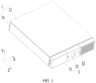
FIG. 1 is a schematic structural diagram of a battery pack according to an embodiment of this application; -
FIG. 2 is another schematic structural diagram of the battery pack shown inFIG. 1 , with a cover plate omitted; -
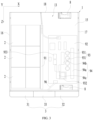
FIG. 3 is a schematic top view of the battery pack shown inFIG. 2 ; -
FIG. 4 is a schematic exploded view of the battery pack shown inFIG. 2 ; -
FIG. 5 is a schematic enlarged view at block A inFIG. 2 ; -
FIG. 6 is a schematic cross-sectional view of a battery pack according to an embodiment of this application; -
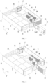
FIG. 7 is a schematic structural diagram of the battery pack shown inFIG. 2 when a first sub-casing is opened; -
FIG. 8 is a schematic structural diagram of the battery pack shown inFIG. 2 when a second sub-casing is opened; -
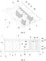
FIG. 9 is a schematic structural diagram of a second casing shown inFIG. 2 ; -
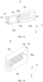
FIG. 10 is a schematic exploded view of the second casing shown inFIG. 9 ; -
FIG. 11 is a schematic diagram of the first sub-casing and the second sub-casing shown inFIG. 10 from another angle; -
FIG. 12 is a schematic enlarged view at circle B inFIG. 11 ; -
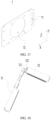
FIG. 13 is a schematic structural diagram of a first plate of a battery pack according to an embodiment of this application; -
FIG. 14 is a schematic enlarged view diagram at circle C inFIG. 11 ; -
FIG. 15 is a schematic structural diagram of the first sub-casing shown inFIG. 11 ; -
FIG. 16 is a schematic structural diagram of the second sub-casing shown inFIG. 11 ; -
FIG. 17 is a schematic structural diagram of a second plate of a battery pack according to an embodiment of this application; -
FIG. 18 is another schematic diagram of the first sub-casing and the second sub-casing shown inFIG. 11 ; and -
FIG. 19 is a schematic exploded view of a battery pack according to another embodiment of this application. - In the accompanying drawings, the figures are not necessarily drawn to scale.
- Numeral references: 1. first casing; 11. first opening; 111. first region; 112. second region; 12. first wall; 13. casing opening; 14. partition portion; 15. second wall; 16. third wall; 17. fourth wall; 18. fifth wall; 2. battery module; 3. second casing;
- 31. first sub-casing; 311. first fitting portion; 312. first portion; 312a. first recess; 312b. third recess; 313. third latch; 314. third portion; 3141. first hole; 3141a. first hole portion; 3141b. second hole portion; 3142. second hole; 315. fourth portion;
- 32. second sub-casing; 321. second fitting portion; 321a. third hole; 322. second portion; 322a. second recess; 323. second protrusion; 324. fourth latch; 325. through hole;
- 33. third sub-casing; 331. first latch; 332. second latch;
- 4. first plate; 41. second opening; 42. third opening; 43. first protrusion;
- 5. second component; 6. first component; 7. second plate; 71. fourth opening; 72. fifth opening; 8. heat dissipation component; 9. control assembly; 91. protruding wall; 92. circuit board; 921. first surface; 922. second surface; 93. control component; 931. capacitor; 932. inductor; 933. control chip; 94. heat conducting plate; 94a. first heat conducting plate; 94b. second heat conducting plate; 94c. third heat conducting plate; 95. thermal conductive adhesive;
- Z. first direction; X. second direction; and Y. third direction.
- To make the objectives, technical solutions, and advantages of some embodiments of this application clearer, the following clearly describes the technical solutions in these embodiments of this application with reference to the accompanying drawings in these embodiments of this application. Apparently, these described embodiments are some but not all of embodiments of this application.
- In the specification, claims, or accompanying drawings of this application, the terms "first", "second", and the like are intended to distinguish between different objects rather than to indicate a particular sequence or relative importance. In these embodiments of this application, the same reference signs denote the same members. For brevity, in different embodiments, detailed descriptions of the same members are not repeated.
- Reference to "embodiment" in this application means that specific features, structures, or characteristics described with reference to the embodiment may be included in at least one embodiment of this application. The word "embodiment" appearing in various places in this specification does not necessarily refer to the same embodiment or an independent or alternative embodiment that is exclusive of other embodiments.
- In the description of this application, it should be noted that unless otherwise specified and defined explicitly, the terms "mounting", "connection", and the like should be understood in their general senses. For example, they may refer to a fixed connection, a detachable connection, or an integral connection, and may refer to a direct connection, an indirect connection via an intermediate medium, or an internal communication between two elements. Persons of ordinary skill in the art can understand specific meanings of these terms in this application as appropriate to specific situations.
- The term "parallel" in some embodiments of this application not only includes the absolutely parallel case, but also includes the approximately parallel case in the conventional understanding of engineering; likewise, the term "perpendicular" not only includes the absolutely perpendicular case, but also includes the approximately perpendicular case in the conventional understanding of engineering. For example, two directions may be considered to be perpendicular if an included angle between the two directions is 80°-90°, and two directions may be considered to be parallel if the included angle between the two directions is 0°-10°.
- The battery module of this application is described below with reference to the accompanying drawings.
- According to
FIGs. 1 to 8 , a battery pack of these embodiments of this application includes afirst casing 1, abattery module 2, and asecond casing 3. Thefirst casing 1 has afirst opening 11. Thebattery module 2 is accommodated in thefirst casing 1. Thesecond casing 3 is connected to thefirst casing 1, thesecond casing 3 includes afirst sub-casing 31 and asecond sub-casing 32, thefirst sub-casing 31 is connected to thefirst casing 1 and covers at least a part of thefirst opening 11, thesecond sub-casing 32 is connected to thefirst casing 1, and thefirst sub-casing 31 and/or thesecond sub-casing 32 is configured to be openable. - In some embodiments, at least one of the
first sub-casing 31 and thesecond sub-casing 32 can be opened, allowing the internal space of thefirst casing 1 to communicate with the external space of the battery pack via thefirst opening 11. The heat generated by thebattery module 2 can be dissipated to the outside of the battery pack via thefirst opening 11, thereby improving the heat dissipation efficiency of thebattery module 2 and the cycling performance of thebattery module 2. During the use of the battery pack, when thebattery module 2 fails, at least one of thefirst sub-casing 31 and thesecond sub-casing 32 can be opened to maintain thebattery module 2 via thefirst opening 11, reducing the maintenance time, simplifying the assembly and disassembly process of the battery pack, and improving the efficiency. - In some embodiments, the
first sub-casing 31 is configured to be openable. - In some embodiments, the second sub-casing 32 covers at least a part of the
first opening 11, and thesecond sub-casing 32 is configured to be openable. - In some embodiments, there may be one or
more battery modules 2. Optionally,multiple battery modules 2 are provided. - The
battery module 2 includes multiple cells, and the multiple cells may be connected in series, in parallel, or in a combination of series and parallel, where being connected in series-parallel means a combination of series and parallel connections of the multiple cells. - The cells may be lithium-ion cells, sodium-lithium-ion cells, sodium-ion cells, magnesium-ion cells, or other types of cells, which is not limited in these embodiments of this application. Optionally, the cells are pouch cells.
- In some embodiments, the
first casing 1 includes afirst wall 12, asecond wall 15, athird wall 16, afourth wall 17, and afifth wall 18. Thefirst wall 12,second wall 15,third wall 16, andfourth wall 17 enclose thefirst opening 11. Thefifth wall 18 is opposite to thefirst opening 11 in the first direction Z. Thethird wall 16 is opposite to thefourth wall 17 along the second direction X, and thefirst wall 12 is opposite to thesecond wall 15 along the third direction Y. For example, the first direction Z, the second direction X, and the third direction Y are perpendicular to each other. - In some embodiments, the
second wall 15, thethird wall 16, and thefourth wall 17 are connected to form a U-shaped frame structure. The frame structure forms acasing opening 13 opposite to thesecond wall 15 in the third direction Y. Thefirst wall 12 covers thecasing opening 13. - In some embodiments, the battery pack further includes a
first plate 4 and asecond plate 7. Thefirst plate 4 is connected to thefirst wall 12, thesecond wall 15, and thethird wall 16, and thefirst plate 4 covers part of thefirst opening 11. Thesecond plate 7 is connected to thefirst wall 12, thesecond wall 15, and thefourth wall 17. Thesecond plate 7 is spaced apart from thefirst plate 4 and covers part of thefirst opening 11. - In some embodiments, the
first wall 12 may be connected to the frame structure by adhering, snap-fitting, welding, or other methods to cover thecasing opening 13. - In some embodiments, the
battery module 2 is arranged on thesecond wall 15. For example, thebattery module 2 is adhered to the surface of thesecond wall 15 opposite to thecasing opening 13 using an adhesive. - In some embodiments, the
first sub-casing 31 is connected to thefirst plate 4. - In some embodiments, the first sub-casing 31 covers part of the
first opening 11. - In some embodiments, the
battery module 2 is disposed opposite to thefirst sub-casing 31 along a first direction Z. When thefirst sub-casing 31 is opened, the heat generated by thebattery module 2 can be dissipated to the outside of the battery pack via thefirst opening 11, thereby improving the heat dissipation efficiency of thebattery module 2 and enhancing the cycling performance of thebattery module 2. - In some embodiments, the battery pack further includes a
control assembly 9 accommodated in thefirst casing 1, and thecontrol assembly 9 is spaced apart from thebattery module 2 along a second direction X perpendicular to the first direction Z. Thecontrol assembly 9 is disposed opposite to thesecond sub-casing 32 along the first direction Z. - In some embodiments, the
control assembly 9 is arranged on thesecond wall 15, for example, fixed to thesecond wall 15 by screws or other fasteners. - Viewed along the first direction Z, the
battery module 2 overlaps thefirst sub-casing 31, and thecontrol assembly 9 overlaps thesecond sub-casing 32. - Spacing the
control assembly 9 apart from thebattery module 2 can reduce the heat transferred between thebattery module 2 and thecontrol assembly 9, minimizing the thermal effect between thebattery module 2 and thecontrol assembly 9, thus improving the cycling performance of thebattery module 2 and the use performance of thecontrol assembly 9. - In some embodiments, the
first opening 11 includes afirst region 111 and asecond region 112, the first sub-casing 31 covers at least a part of thefirst region 111, and the second sub-casing 32 covers at least a part of thesecond region 112. For example, thesecond sub-casing 32 is configured to be openable. - The
first region 111 and thesecond region 112 can be connected or separated. - The
second sub-casing 32 can be opened, and the heat generated by thecontrol assembly 9 can be dissipated to the outside of the battery pack through thesecond region 112, thereby improving the heat dissipation efficiency of thecontrol assembly 9 and improving the use performance of thecontrol assembly 9. During the use of the battery pack, when thecontrol assembly 9 fails, thesecond sub-casing 32 can be opened to maintain thecontrol assembly 9 through thesecond region 112, reducing the maintenance time, simplifying the assembly and disassembly process of the battery pack, and improving the efficiency. - In some embodiments, viewed from the second direction X, the
battery module 2 overlaps thecontrol assembly 9. In this embodiment, space is is configured for reduce the distance between thebattery module 2 and thecontrol assembly 9, facilitating harness connection. - In some embodiments, in the first direction Z, the
battery module 2 is closer to thefifth wall 18 than thecontrol assembly 9. The space between thefifth wall 18 and thecontrol assembly 9 helps to improve heat dissipation, facilitates harness arrangement, reduces interference between harnesses, and lowers the probability of harness failure. - In some embodiments, the
control assembly 9 is electrically connected to thebattery module 2, enabling the control of charging and discharging of thebattery module 2. The control assembly is fixed to thefirst casing 1. For example, thecontrol assembly 9 is adhered to thesecond wall 15 of thefirst casing 1. - In some embodiments, the
control assembly 9 includes acircuit board 92, acontrol component 93, and aheat conducting plate 94, thecircuit board 92 includes afirst surface 921 and asecond surface 922 opposite to each other along a third direction Y, and the third direction Y is perpendicular to the first direction Z and the second direction X. Thesecond surface 922 is connected to thefirst casing 1, and thecontrol component 93 and theheat conducting plate 94 are disposed on thefirst surface 921. Thefirst surface 921 faces thefirst wall 12, and thesecond surface 922 faces away from thefirst wall 12. - During the operation of the battery pack, the
heat conducting plate 94 can conduct the heat generated by thecircuit board 92 and the heat generated by thecontrol component 93 to dissipate the heat outwards, reducing the temperature of thecircuit board 92 and thecontrol component 93, and lowering the risk of failure of thecircuit board 92 and thecontrol component 93. - In some embodiments, the
heat conducting plate 94 includes a material with good thermal conductivity, such as a metal material, where the metal material may be copper, aluminum, steel, or other materials. Optionally, the surface of theheat conducting plate 94 may be coated with an insulating material. - In some embodiments, the
heat conducting plate 94 may be an aluminum plate. - In some embodiments, the
control component 93 includes acontrol chip 933. Thecontrol chip 933 can be configured for control the working state of thebattery module 2. For example, thecontrol chip 933 can be configured for control the charge and discharge of thebattery module 2. In some embodiments, along the first direction Z, thecontrol chip 933 is located between thebattery module 2 and theheat conducting plate 94, helping to improve the heat dissipation of the battery pack. - For example, the
circuit board 92 is of a plate-shaped structure. Thefirst surface 921 and thesecond surface 922 are planar. - In some embodiments, the
circuit board 92 includes a printed circuit board (PCB, Printed Circuit Board). - In some embodiments, viewed along the first direction Z, the
heat conducting plate 94 is higher than thecontrol component 93 in the third direction Y. Theheat conducting plate 94 is higher than thecontrol component 93 in the third direction Y, increasing the heat dissipation area of theheat conducting plate 94 and improving the heat dissipation efficiency of theheat conducting plate 94. - In some embodiments, the battery pack further includes a
heat dissipation component 8 disposed on thefirst casing 1, where theheat dissipation component 8 is opposite to at least a part of theheat conducting plate 94 along the first direction Z. Theheat dissipation component 8 is arranged on thefifth wall 18, for example, fixed to thefifth wall 18 by screws or other fasteners. Along the first direction Z, the projections of theheat dissipation component 8 and thesecond sub-casing 32 overlap, which helps to improve the heat dissipation of the battery pack. Theheat dissipation component 8 can be configured to dissipate the heat on theheat conducting plate 94 to the outside of the battery pack. Theheat dissipation component 8 being opposite to at least a part of theheat conducting plate 94 can improve the heat dissipation efficiency. - In some embodiments, the
control chip 933 can be configured for control the start and stop of theheat dissipation component 8. - In some embodiments, the
heat dissipation component 8 may be mounted on thesecond plate 7. - In some embodiments, the
heat dissipation component 8 includes, but is not limited to, a fan or air conditioner, and theheat dissipation component 8 has a heat dissipation function. - In some embodiments, the
heat dissipation component 8 includes two fans. The two fans are mounted on thefirst casing 1 and are respectively located on both sides of thecontrol assembly 9 along the first direction Z. During the use of the battery pack, one fan draws air into thefirst casing 1, and the other fan exhausts air out of thefirst casing 1. The two fans cause airflow to pass through theheat conducting plate 94 of thecontrol assembly 9, thereby dissipating the heat on theheat conducting plate 94 to the outside of thefirst casing 1. - In some embodiments, the
control component 93 includes acapacitor 931, and theheat dissipation component 8 is opposite to at least a part of thecapacitor 931 along the first direction Z. There may be one ormore capacitors 931. For example, thecapacitor 931 can store energy and provide output energy. Optionally, thecapacitor 931 can also filter interference and reduce circuit current ripple. - The
heat dissipation component 8 can be configured to dissipate the heat on thecapacitor 931 to the outside of the battery pack. Theheat dissipation component 8 being opposite to at least a part of thecapacitor 931 can improve the heat dissipation efficiency. - In some embodiments, the
heat conducting plate 94 includes a firstheat conducting plate 94a and a secondheat conducting plate 94b spaced apart along the second direction X. Viewed along the third direction Y, thecapacitor 931 is located between the firstheat conducting plate 94a and the secondheat conducting plate 94b in the second direction X. - The first
heat conducting plate 94a and the secondheat conducting plate 94b can block thecapacitor 931 from both sides to reduce the heat dissipated from thecapacitor 931 to the surroundings, thereby reducing the thermal effect of thecapacitor 931 on other components. The airflow passing through the space between the firstheat conducting plate 94a and the secondheat conducting plate 94b can carry away the heat generated by thecapacitor 931, thereby reducing the temperature of thecapacitor 931 and improving the operation performance of thecapacitor 931. - In some embodiments, the first
heat conducting plate 94a is connected to thefirst wall 12 via a thermalconductive adhesive 95, and the secondheat conducting plate 94b is connected to thefirst wall 12 via the thermalconductive adhesive 95. The heat on the firstheat conducting plate 94a and the heat on the secondheat conducting plate 94b can be dissipated outward via thefirst wall 12. - In some embodiments, the
second sub-casing 32 is opposite to theheat dissipation component 8 along the first direction Z. Thesecond sub-casing 32 is provided with multiple throughholes 325, and at least some of the multiple throughholes 325 are opposite to theheat dissipation component 8 along the first direction Z. - The
heat dissipation component 8 dissipates the internal heat of the battery pack to the outside of the battery pack via the multiple throughholes 325 to improve heat dissipation efficiency. - In some embodiments, the
control component 93 also includes aninductor 932. Optionally, theinductor 932 is a power inductor. - In some embodiments, the
heat dissipation component 8 is opposite to at least a part of theinductor 932 along the first direction Z. - In some embodiments, the
heat conducting plate 94 includes a thirdheat conducting plate 94c. The thirdheat conducting plate 94c is connected to theinductor 932. The thirdheat conducting plate 94c can absorb the heat generated by theinductor 932 and dissipate the heat outward, thereby lowering the temperature of theinductor 932 and improving the use performance of theinductor 932. - In some embodiments, the third
heat conducting plate 94c is connected to thefirst wall 12 via the thermalconductive adhesive 95. - In some embodiments, viewed along the first direction Z, the
battery module 2 is higher than theheat conducting plate 94 in the third direction Y. - In some embodiments, viewed along the third direction Y, the second
heat conducting plate 94b is located between thecontrol chip 933 and thecapacitor 931 in the second direction X. - The second
heat conducting plate 94b can separate thecontrol chip 933 and thecapacitor 931, reducing the heat conducted from thecapacitor 931 to thecontrol chip 933 and lowering the temperature of thecontrol chip 933, thus improving the performance of thecontrol chip 933 and prolonging its service life. - In some embodiments, the battery pack further includes a protruding
wall 91, where the protrudingwall 91 is disposed between thebattery module 2 and thecontrol assembly 9. The protrudingwall 91 can isolate the heat generated by thecontrol assembly 9, reducing the thermal effect on thebattery module 2, lowering the risk of thermal runaway of the battery module, and improving the safety. - In some embodiments, the protruding
wall 91 protrudes out of thesecond wall 15 and is fixed to thesecond wall 15. - In some embodiments, in the third direction Y, the height of the protruding
wall 91 is less than or equal to the height of thethird wall 16, and the height of the protrudingwall 91 is less than or equal to the height of thefourth wall 17. - In some embodiments, the protruding
wall 91 and thesecond wall 15 are integrally formed, which helps to enhance the structural strength of thefirst casing 1. In some embodiments, the protrudingwall 91 may be fixed to thesecond wall 15 by screws or other fasteners. - In some embodiments,
multiple cables 96 are provided in the battery pack. In the second direction X, a routing channel is reserved between thecontrol assembly 9 and thebattery module 2, and at least some of thecables 96 are arranged in the routing channel. Arranging the routing channel between thecontrol assembly 9 and thebattery module 2 facilitates unified mounting and fixing of themultiple cables 96, and can also enlarge the thermal insulation gap between thecontrol assembly 9 and thebattery module 2. Some of thecables 96 may be located between thecontrol assembly 9 and thebattery module 2 in the second direction X. - In some embodiments, the
control assembly 9 and thebattery module 2 may be electrically connected via at least onecable 96. - In some embodiments, the battery pack further includes a
first component 6 disposed on thefirst casing 1, and thecontrol assembly 9 is connected to thefirst component 6 via acable 96. - The
first component 6 is a component of the battery pack is configured for achieve a specific function. For example, thefirst component 6 includes a display screen. - The
control assembly 9 can transmit a signal to thefirst component 6 via thecable 96, enabling thefirst component 6 to perform a predetermined function. - In some embodiments, the second casing further includes a
third sub-casing 33, and thethird sub-casing 33 is connected to thefirst sub-casing 31 and thesecond sub-casing 32. In the first direction Z, the third sub-casing 33 covers at least a part of thefirst component 6. Thethird sub-casing 33 serves to protect thefirst component 6, reducing the risk of damage to thefirst component 6 when the battery pack is subjected to external impact. - As shown in
FIGs. 3 ,4 , and9-18 , thefirst sub-casing 31 is provided with a firstfitting portion 311, thesecond sub-casing 32 is provided with a secondfitting portion 321, the firstfitting portion 311 is configured to be movable from a first position of the secondfitting portion 321 to a second position, the firstfitting portion 311 is snap-fitted with thesecond sub-casing 32 at the first position, and the firstfitting portion 311 is rotatably connected to thesecond sub-casing 32 at the second position. - When it is necessary to open the
first sub-casing 31, thefirst sub-casing 31 is moved so that the firstfitting portion 311 of the first sub-casing 31 moves to the second position, and then thefirst sub-casing 31 is rotated to open thefirst sub-casing 31. When it is necessary to close thefirst sub-casing 31, thefirst sub-casing 31 is rotated to a preset angle and then moved from the second position to the first position, so that the firstfitting portion 311 is snap-fitted to thesecond sub-casing 32. - When it is necessary to open the
second sub-casing 32, thesecond sub-casing 32 may be correspondingly moved and rotated so that the firstfitting portion 311 moves from the first position of the secondfitting portion 321 to the second position. - In some embodiments, the first position and the second position are disposed along a second direction X. The
first sub-casing 31 includes afirst portion 312, thesecond sub-casing 32 includes asecond portion 322, thefirst portion 312 and thesecond portion 322 are arranged along the second direction X, and the firstfitting portion 311 and the secondfitting portion 321 are located between thefirst portion 312 and thesecond portion 322 in the second direction X. - In some embodiments, the
second casing 3 further includes athird sub-casing 33, and at least a part of thethird sub-casing 33 is located between thefirst portion 312 and thesecond portion 322 and abuts against thefirst portion 312 and thesecond portion 322. - The third sub-casing 33 can limit the relative movement of the
first portion 312 and thesecond portion 322 in the second direction X, so that the firstfitting portion 311 remains at the first position of the secondfitting portion 321, achieving the fixing between thefirst sub-casing 31 and thesecond sub-casing 32. - In some embodiments, in the second direction X, a surface of the
first portion 312 facing thesecond portion 322 is provided with afirst recess 312a, and a surface of thesecond portion 322 facing thefirst portion 312 is provided with asecond recess 322a. Afirst latch 331 and asecond latch 332 are respectively disposed at two ends of thethird sub-casing 33 along the second direction X, thefirst latch 331 is inserted into thefirst recess 312a, and thesecond latch 332 is inserted into thesecond recess 322a. - The
third sub-casing 33 is snap-fitted to thefirst portion 312 and thesecond portion 322 via thefirst latch 331 and thesecond latch 332, respectively, to achieve the fixing of thefirst sub-casing 31, thesecond sub-casing 32, and thethird sub-casing 33. - In some embodiments, the battery pack further includes a
first plate 4, where thefirst plate 4 is located on a side of thefirst portion 312 facing thefirst casing 1 and is connected to thefirst casing 1, and thefirst plate 4 covers at least a part of thefirst opening 11. Thefirst plate 4 is provided with asecond opening 41, thefirst sub-casing 31 includes athird latch 313, thethird latch 313 is disposed on an end surface of thefirst portion 312 facing thefirst casing 1, and thethird latch 313 passes through thesecond opening 41. Thethird latch 313 is snap-fitted with thefirst plate 4 when the firstfitting portion 311 is located at the first position, and thethird latch 313 is released from thefirst plate 4 when the firstfitting portion 311 is located at the second position. - The
first plate 4 is fixed to thefirst casing 1. For example, thefirst plate 4 may be fixed to thefirst casing 1 by a fastener, such as a screw. - The
first sub-casing 31 is snap-fitted to thefirst plate 4 through engagement between thethird latch 313 and thesecond opening 41 to reduce the risk of rotation of thefirst sub-casing 31 when the firstfitting portion 311 is at the first position. - In some embodiments, the
first plate 4 is provided with athird opening 42. The battery pack further includes asecond component 5, and thesecond component 5 passes through thethird opening 42 to be electrically connected to thebattery module 2. A side of thefirst portion 312 facing thefirst plate 4 is provided with athird recess 312b, and at least a part of thesecond component 5 is accommodated in thethird recess 312b. The arrangement of thethird opening 42 can reduce the risk of interference between thefirst plate 4 and thesecond component 5. Thethird recess 312b can provide an accommodation space for thesecond component 5 and can provide protection for thesecond component 5 from the outside. For example, thesecond component 5 can include a power harness connected to thebattery module 2. - When the
second component 5 fails, thefirst sub-casing 31 is opened to maintain thesecond component 5. - In some embodiments, two
third openings 42 are provided, and the twothird openings 42 are respectively opposite to the twobattery modules 2 in the first direction Z. Thesecond component 5 can pass through the twothird openings 42 to electrically connect the twobattery modules 2. - In some embodiments, the
first sub-casing 31 includes athird portion 314 connected to thefirst portion 312, and thethird portion 314 is located between thefirst portion 312 and thesecond portion 322 in the second direction X. The firstfitting portion 311 is disposed at thethird portion 314. - In some embodiments, a side of the
third portion 314 facing thefirst casing 1 is provided with afirst hole 3141, and thefirst plate 4 is provided with afirst protrusion 43 inserted into thefirst hole 3141. Thefirst protrusion 43 is inserted into thefirst hole 3141 to limit the movement of thefirst sub-casing 31 along the second direction X. - In some embodiments, the
first hole 3141 includes afirst hole portion 3141a and asecond hole portion 3141b communicating with each other, and a hole size of thesecond hole portion 3141b is larger than a hole size of thefirst hole portion 3141a. Thefirst protrusion 43 is inserted into thefirst hole portion 3141a when the firstfitting portion 311 is located at the first position, and thefirst protrusion 43 is inserted into thesecond hole portion 3141b when the firstfitting portion 311 is located at the second position. - When the first
fitting portion 311 is at the first position, thefirst protrusion 43 fits with thefirst hole portion 3141a having a smaller hole size, so that thefirst protrusion 43 is snap-fitted to thefirst sub-casing 31. When the firstfitting portion 311 is at the second position, thefirst protrusion 43 is inserted into thesecond hole portion 3141b. When thefirst sub-casing 31 is rotated in the opening direction, thesecond hole portion 3141b having a larger hole size can provide space for the rotation of thefirst protrusion 43, making it less likely to interfere with the rotation of thefirst protrusion 43. When thefirst sub-casing 31 is rotated in the closing direction, thefirst protrusion 43 is more easily inserted into thesecond hole portion 3141b having a larger hole size. - In some embodiments, the
third portion 314 is provided with asecond hole 3142. The battery pack further includes afirst component 6, the second casing includes athird sub-casing 33, at least a part of thefirst component 6 is accommodated in thesecond hole 3142, and at least a part of thethird sub-casing 33 is located between thefirst portion 312 and thesecond portion 322 and covers at least a part of thefirst component 6. - The
second hole 3142 provides space for thefirst component 6, reducing the risk of interference between thefirst component 6 and thefirst sub-casing 31. The third sub-casing 33 covers at least a part of thefirst component 6 to provide protection, reducing the risk of damage to thefirst component 6 when the battery pack is subjected to external impact. - In some embodiments, the
first component 6 includes a display screen. Thethird sub-casing 33 exposes part of the display screen, which is conducive for the staff to view the working state of the battery pack. - In some embodiments, the
second sub-casing 32 includes asecond protrusion 323, thesecond protrusion 323 protrudes out of a surface of thesecond portion 322 facing thefirst portion 312 along the second direction X, and the secondfitting portion 321 is disposed at thesecond protrusion 323. The first sub-casing 31 further includes afourth portion 315, thefourth portion 315 is connected to thefirst portion 312 and opposite to thesecond protrusion 323 along a third direction Y, and the third direction Y is perpendicular to the second direction X. The firstfitting portion 311 protrudes out of a surface of thefourth portion 315 facing thesecond protrusion 323 along the third direction Y and is inserted into the secondfitting portion 321. - The second
fitting portion 321 may be a hole, a slot, a notch, or another structure. - In some embodiments, the second
fitting portion 321 includes athird hole 321a. The size of thethird hole 321a at the second position along the first direction Z is larger than the size of thethird hole 321a at the first position along the first direction Z. The first direction Z is perpendicular to the second direction X and the third direction Y. - The size of the
third hole 321a at the first position along the first direction Z is smaller. The firstfitting portion 311 can be snap-fitted with the wall of thethird hole 321a at the first position of thethird hole 321a. The size of thethird hole 321a at the second position along the first direction Z is larger, and the firstfitting portion 311 can rotate at the second position of thethird hole 321a. - In some embodiments, two
second protrusions 323 and twofourth portions 315 are provided, the twosecond protrusions 323 are spaced apart along the third direction Y, and the twofourth portions 315 are located between the twosecond protrusions 323. - Each of the
second protrusions 323 is provided with athird hole 321a, and each of the twofourth portions 315 is provided with a firstfitting portion 311. The two firstfitting portions 311 are engaged with the twothird holes 321a, improving the stability of the connection between thefirst sub-casing 31 and thesecond sub-casing 32. - In some embodiments, the
second portion 322 covers at least a part of thefirst opening 11. In some embodiments, in the first direction Z, thesecond portion 322 is opposite to at least a part of theheat dissipation component 8. - In some embodiments, the battery pack further includes a
second plate 7, where thesecond plate 7 is located on a side of thesecond portion 322 facing thefirst casing 1 and is connected to thefirst casing 1, and thesecond plate 7 covers at least a part of thefirst opening 11. Thesecond plate 7 and thesecond portion 322 are arranged along the first direction Z. Thesecond plate 7 is provided with afourth opening 71, thesecond sub-casing 32 includes afourth latch 324, thefourth latch 324 is disposed on an end surface of thesecond portion 322 facing thefirst casing 1, and thefourth latch 324 passes through thefourth opening 71. Thefourth latch 324 is snap-fitted with thesecond plate 7 when the firstfitting portion 311 is located at the first position, and thefourth latch 324 is released from thesecond plate 7 when the firstfitting portion 311 is located at the second position. - The
second plate 7 is fixed to thefirst casing 1. For example, thesecond plate 7 may be fixed to thefirst casing 1 by a fastener. - The
second sub-casing 32 is snap-fitted to thesecond plate 7 through engagement between thefourth latch 324 and thefourth opening 71 to reduce the risk of rotation of thesecond sub-casing 32 when the firstfitting portion 311 is at the first position. - In some embodiments, at least a part of the
heat dissipation component 8 is accommodated in thefirst casing 1. Thesecond plate 7 is provided with afifth opening 72, theheat dissipation component 8 is opposite to thefifth opening 72 along the first direction Z, and thesecond portion 322 covers thefifth opening 72. Driven by theheat dissipation component 8, the gas outside the battery pack can enter the battery pack via thefifth opening 72, or the gas inside the battery pack can be discharged to the outside of the battery pack via thefifth opening 72. - As shown in
FIG. 19 , in some embodiments, the first casing includes apartition portion 14, and thepartition portion 14 separates thefirst opening 11 into thefirst region 111 and thesecond region 112. - The
partition portion 14 can support the part of thefirst casing 1 enclosing thefirst opening 11, reducing deformation of thefirst opening 11, thereby enhancing the stability and safety of the battery pack.
Claims (32)
- A battery pack, comprising:a first casing having a first opening;a battery module accommodated in the first casing; anda second casing connected to the first casing, wherein the second casing comprises a first sub-casing and a second sub-casing, the first sub-casing is connected to the first casing and covers at least a part of the first opening, the second sub-casing is connected to the first casing, and the first sub-casing and/or the second sub-casing is configured to be openable.
- The battery pack according to claim 1, wherein the battery module is disposed opposite to the first sub-casing along a first direction;the battery pack further comprises a control assembly accommodated in the first casing, and the control assembly is spaced apart from the battery module along a second direction perpendicular to the first direction; andthe control assembly is disposed opposite to the second sub-casing along the first direction.
- The battery pack according to claim 1 or 2, wherein the first opening comprises a first region and a second region, the first sub-casing covers at least a part of the first region, and the second sub-casing covers at least a part of the second region.
- The battery pack according to claim 3, wherein the first casing comprises a partition portion, and the partition portion separates the first opening into the first region and the second region.
- The battery pack according to claim 2, wherein the control assembly comprises a circuit board, a control component, and a heat conducting plate; the circuit board comprises a first surface and a second surface opposite to each other along a third direction, and the third direction is perpendicular to the first direction and the second direction; and
the second surface is connected to the first casing, and the control component and the heat conducting plate are disposed on the first surface. - The battery pack according to claim 5, wherein the control component comprises a control chip, and along the first direction, the control chip is located between the battery module and the heat conducting plate.
- The battery pack according to claim 5, wherein viewed along the first direction, the heat conducting plate is higher than the control component in the third direction.
- The battery pack according to claim 5, further comprising a heat dissipation component disposed on the first casing, the heat dissipation component is opposite to at least a part of the heat conducting plate along the first direction.
- The battery pack according to claim 8, wherein the control component comprises a capacitor, and the heat dissipation component is opposite to at least a part of the capacitor along the first direction.
- The battery pack according to claim 9, wherein the heat conducting plate comprises a first heat conducting plate and a second heat conducting plate spaced apart along the second direction; and
viewed along the third direction, the capacitor is located between the first heat conducting plate and the second heat conducting plate in the second direction. - The battery pack according to claim 10, wherein the control component comprises a control chip, and viewed along the third direction, the second heat conducting plate is located between the control chip and the capacitor in the second direction.
- The battery pack according to claim 8, wherein the second sub-casing is opposite to the heat dissipation component along the first direction; and
the second sub-casing is provided with multiple through holes, and at least some of the multiple through holes are opposite to the heat dissipation component along the first direction. - The battery pack according to claim 5, wherein viewed along the first direction, the battery module is higher than the heat conducting plate in the third direction.
- The battery pack according to claim 2, further comprising a protruding wall, wherein the protruding wall is disposed between the battery module and the control assembly.
- The battery pack according to claim 2, wherein the battery pack further comprises a first component disposed on the first casing, and the control assembly is connected to the first component via a cable.
- The battery pack according to claim 15, wherein the second casing further comprises a third sub-casing, and the third sub-casing is connected to the first sub-casing and the second sub-casing; and
in the first direction, the third sub-casing covers at least a part of the first component. - The battery pack according to claim 1, wherein the first sub-casing is provided with a first fitting portion, the second sub-casing is provided with a second fitting portion, the first fitting portion is configured to be movable from a first position of the second fitting portion to a second position, the first fitting portion is snap-fitted with the second sub-casing at the first position, and the first fitting portion is rotatably connected to the second sub-casing at the second position.
- The battery pack according to claim 17, wherein the first position and the second position are disposed along a second direction; and
the first sub-casing comprises a first portion, the second sub-casing comprises a second portion, the first portion and the second portion are arranged along the second direction, and the first fitting portion and the second fitting portion are located between the first portion and the second portion in the second direction. - The battery pack according to claim 18, wherein the second casing further comprises a third sub-casing, and at least a part of the third sub-casing is located between the first portion and the second portion and abuts against the first portion and the second portion.
- The battery pack according to claim 19, wherein in the second direction, a surface of the first portion facing the second portion is provided with a first recess, and a surface of the second portion facing the first portion is provided with a second recess; and
a first latch and a second latch are respectively disposed at two ends of the third sub-casing along the second direction, the first latch is inserted into the first recess, and the second latch is inserted into the second recess. - The battery pack according to claim 18, further comprising a first plate, the first plate is located on a side of the first portion facing the first casing and is connected to the first casing, and the first plate covers at least a part of the first opening;the first plate is provided with a second opening, the first sub-casing comprises a third latch, the third latch is disposed on an end surface of the first portion facing the first casing, and the third latch passes through the second opening; andthe third latch is snap-fitted with the first plate when the first fitting portion is located at the first position, and the third latch is released from the first plate when the first fitting portion is located at the second position.
- The battery pack according to claim 21, wherein the first plate is provided with a third opening, the battery pack further comprises a second component, and the second component passes through the third opening to be electrically connected to the battery module; and
a side of the first portion facing the first plate is provided with a third recess, and at least a part of the second component is accommodated in the third recess. - The battery pack according to claim 21, wherein the first sub-casing comprises a third portion connected to the first portion, and the third portion is located between the first portion and the second portion along the second direction; and
the first fitting portion is disposed at the third portion. - The battery pack according to claim 23, wherein a side of the third portion facing the first casing is provided with a first hole, and the first plate is provided with a first protrusion inserted into the first hole;the first hole comprises a first hole portion and a second hole portion communicating with each other, and a hole size of the second hole portion is larger than a hole size of the first hole portion; andthe first protrusion is inserted into the first hole portion when the first fitting portion is located at the first position, and the first protrusion is inserted into the second hole portion when the first fitting portion is located at the second hole portion.
- The battery pack according to claim 23, wherein the third portion is provided with a second hole; and
the battery pack further comprises a first component, the second casing comprises a third sub-casing, at least a part of the first component is accommodated in the second hole, and at least a part of the third sub-casing is located between the first portion and the second portion and covers at least a part of the first component. - The battery pack according to claim 25, wherein the first component comprises a display screen.
- The battery pack according to claim 18, wherein the second sub-casing comprises a second protrusion, the second protrusion protrudes out of a surface of the second portion facing the first portion along the second direction, and the second fitting portion is disposed at the second protrusion;the first sub-casing further comprises a fourth portion, the fourth portion is connected to the first portion and opposite to the second protrusion along a third direction, and the third direction is perpendicular to the second direction; andthe first fitting portion protrudes out of a surface of the fourth portion facing the second protrusion along the third direction and is inserted into the second fitting portion.
- The battery pack according to claim 27, wherein the second fitting portion has a third hole, a size of the third hole at the second position along the third direction is larger than a size of the third hole at the first position along the third direction, and the third direction is perpendicular to the second direction and the third direction.
- The battery pack according to claim 27, wherein two second protrusions and two fourth portions are provided, the two second protrusions are spaced apart along the third direction, and the two fourth portions are located between the two second protrusions.
- The battery pack according to claim 18, wherein the second portion covers at least a part of the first opening.
- The battery pack according to claim 30, further comprising a second plate, the second plate is located on a side of the second portion facing the first casing and is connected to the first casing, and the second plate covers at least a part of the first opening;the second plate and the second portion are arranged along a third direction;the second plate is provided with a fourth opening, the second sub-casing comprises a fourth latch, the fourth latch is disposed on an end surface of the second portion facing the first casing, and the fourth latch passes through the fourth opening; andthe fourth latch is snap-fitted with the second plate when the first fitting portion is located at the first position, and the fourth latch is released from the second plate when the first fitting portion is located at the second position.
- The battery pack according to claim 31, further comprising a heat dissipation component, at least a part of the heat dissipation component is accommodated in the first casing; and
the second plate is provided with a fifth opening, the heat dissipation component is opposite to the fifth opening along the third direction, and the second portion covers the fifth opening.
Applications Claiming Priority (1)
| Application Number | Priority Date | Filing Date | Title |
|---|---|---|---|
| PCT/CN2022/124080 WO2024077414A1 (en) | 2022-10-09 | 2022-10-09 | Battery pack |
Publications (2)
| Publication Number | Publication Date |
|---|---|
| EP4579874A1 true EP4579874A1 (en) | 2025-07-02 |
| EP4579874A4 EP4579874A4 (en) | 2026-01-14 |
Family
ID=90668509
Family Applications (1)
| Application Number | Title | Priority Date | Filing Date |
|---|---|---|---|
| EP22961612.3A Pending EP4579874A4 (en) | 2022-10-09 | 2022-10-09 | BATTERY PACK |
Country Status (5)
| Country | Link |
|---|---|
| US (1) | US20250239688A1 (en) |
| EP (1) | EP4579874A4 (en) |
| JP (1) | JP7836467B2 (en) |
| CN (1) | CN120035904A (en) |
| WO (1) | WO2024077414A1 (en) |
Families Citing this family (1)
| Publication number | Priority date | Publication date | Assignee | Title |
|---|---|---|---|---|
| US12302534B1 (en) * | 2024-12-23 | 2025-05-13 | Guangdong Aoyun Technology Co., Ltd. | Wireless charging power bank |
Family Cites Families (18)
| Publication number | Priority date | Publication date | Assignee | Title |
|---|---|---|---|---|
| JPH1168341A (en) * | 1997-08-21 | 1999-03-09 | Saitama Nippon Denki Kk | Enclosure structure of equipment |
| JP2002046480A (en) | 2000-07-31 | 2002-02-12 | Nippon Yusoki Co Ltd | Case cover device |
| JP5570286B2 (en) | 2010-04-22 | 2014-08-13 | キヤノン株式会社 | Electronics |
| JP5601960B2 (en) | 2010-10-14 | 2014-10-08 | 株式会社東芝 | Power storage system |
| JP4969691B1 (en) | 2011-02-04 | 2012-07-04 | 三菱重工業株式会社 | Storage tool and battery system including the same |
| JP6200675B2 (en) | 2012-04-13 | 2017-09-20 | 日立オートモティブシステムズ株式会社 | Battery block and secondary battery module |
| JP2013191582A (en) | 2013-06-07 | 2013-09-26 | Panasonic Corp | Portable medical device |
| KR102327156B1 (en) * | 2014-12-30 | 2021-11-16 | 에이치엘그린파워 주식회사 | Battery pack for preventing gas leak |
| JP2016134449A (en) | 2015-01-16 | 2016-07-25 | 株式会社東芝 | Electric apparatus |
| JP6819991B2 (en) | 2016-08-16 | 2021-01-27 | 株式会社ユピテル | apparatus |
| KR102005489B1 (en) * | 2016-11-02 | 2019-07-30 | 주식회사 엘지화학 | Battery pack |
| KR101928072B1 (en) * | 2016-12-30 | 2018-12-11 | 주식회사 유라코퍼레이션 | Hinge structure of battery cell module |
| KR102371373B1 (en) * | 2018-12-06 | 2022-03-04 | 주식회사 엘지에너지솔루션 | Battery module |
| KR102407165B1 (en) * | 2019-01-03 | 2022-06-10 | 주식회사 엘지에너지솔루션 | Battery pack and apparatus for assembling battery pack |
| CN209786030U (en) * | 2019-06-10 | 2019-12-13 | 东软睿驰汽车技术(沈阳)有限公司 | battery pack and shell thereof |
| CN214043868U (en) * | 2020-12-31 | 2021-08-24 | 北京科易动力科技有限公司 | Cabinet type energy storage battery pack |
| US20230238643A1 (en) | 2021-03-25 | 2023-07-27 | Lg Energy Solution, Ltd. | Power storage apparatus |
| CN115084683A (en) * | 2022-07-22 | 2022-09-20 | 深圳市欣旺达综合能源服务有限公司 | Battery pack and power supply |
-
2022
- 2022-10-09 WO PCT/CN2022/124080 patent/WO2024077414A1/en not_active Ceased
- 2022-10-09 EP EP22961612.3A patent/EP4579874A4/en active Pending
- 2022-10-09 CN CN202280100863.9A patent/CN120035904A/en active Pending
- 2022-10-09 JP JP2025518650A patent/JP7836467B2/en active Active
-
2025
- 2025-04-09 US US19/173,901 patent/US20250239688A1/en active Pending
Also Published As
| Publication number | Publication date |
|---|---|
| JP7836467B2 (en) | 2026-03-26 |
| JP2025531531A (en) | 2025-09-19 |
| WO2024077414A1 (en) | 2024-04-18 |
| EP4579874A4 (en) | 2026-01-14 |
| US20250239688A1 (en) | 2025-07-24 |
| CN120035904A (en) | 2025-05-23 |
Similar Documents
| Publication | Publication Date | Title |
|---|---|---|
| JP6138688B2 (en) | Power supply device, vehicle including the same, and power storage device | |
| JP5723991B2 (en) | Battery pack with compact structure | |
| CN114094244B (en) | Battery packs and electrical equipment | |
| JP2007048750A (en) | Battery module | |
| EP1753068A1 (en) | Battery module | |
| KR20190070006A (en) | Battery Pack | |
| EP4148868A1 (en) | End cover assembly, battery cell, battery, and device using battery | |
| US20250239688A1 (en) | Battery pack | |
| WO2013031614A1 (en) | Power supply device, vehicle provided with same, and power storage device | |
| EP4002570A1 (en) | Battery module and battery pack comprising same | |
| CN114069126B (en) | Battery packs, battery pack systems and electrical equipment | |
| WO2021206383A1 (en) | Battery pack and device including same | |
| CN113097639A (en) | a battery pack | |
| WO2025002374A1 (en) | Energy storage module and power supply | |
| CN219106299U (en) | Battery pack and power utilization device | |
| EP3772122B1 (en) | Battery module with a multifunctional end-plate | |
| WO2021221296A1 (en) | Battery module and battery pack comprising same | |
| US20230307740A1 (en) | Battery cell, battery, apparatus, and method and device for manufacturing battery cell | |
| CN118336268A (en) | Battery cell modules, battery packs and energy storage boxes | |
| JP5620570B2 (en) | Secondary battery module | |
| KR101483130B1 (en) | Battery Pack | |
| CN223006835U (en) | Battery pack | |
| US20250286189A1 (en) | Battery module and battery pack with structurally integrated arrangement for side terminal cells | |
| CN223598760U (en) | A lithium-ion battery | |
| EP4439783A2 (en) | Battery pack and electrical device |
Legal Events
| Date | Code | Title | Description |
|---|---|---|---|
| STAA | Information on the status of an ep patent application or granted ep patent |
Free format text: STATUS: THE INTERNATIONAL PUBLICATION HAS BEEN MADE |
|
| PUAI | Public reference made under article 153(3) epc to a published international application that has entered the european phase |
Free format text: ORIGINAL CODE: 0009012 |
|
| STAA | Information on the status of an ep patent application or granted ep patent |
Free format text: STATUS: REQUEST FOR EXAMINATION WAS MADE |
|
| 17P | Request for examination filed |
Effective date: 20250328 |
|
| AK | Designated contracting states |
Kind code of ref document: A1 Designated state(s): AL AT BE BG CH CY CZ DE DK EE ES FI FR GB GR HR HU IE IS IT LI LT LU LV MC ME MK MT NL NO PL PT RO RS SE SI SK SM TR |
|
| REG | Reference to a national code |
Ref country code: DE Ref legal event code: R079 Free format text: PREVIOUS MAIN CLASS: H01M0010610000 Ipc: H01M0050271000 |
|
| A4 | Supplementary search report drawn up and despatched |
Effective date: 20251212 |
|
| DAV | Request for validation of the european patent (deleted) | ||
| DAX | Request for extension of the european patent (deleted) | ||
| RIC1 | Information provided on ipc code assigned before grant |
Ipc: H01M 50/271 20210101AFI20251208BHEP Ipc: H01M 10/42 20060101ALI20251208BHEP Ipc: H01M 10/613 20140101ALI20251208BHEP Ipc: H01M 10/6563 20140101ALI20251208BHEP Ipc: H01M 50/258 20210101ALI20251208BHEP Ipc: H01M 50/284 20210101ALI20251208BHEP Ipc: H01M 50/251 20210101ALN20251208BHEP |