EP4579869A1 - Apparatus for detecting defects of battery cell and method for detecting defects of battery cell - Google Patents
Apparatus for detecting defects of battery cell and method for detecting defects of battery cell Download PDFInfo
- Publication number
- EP4579869A1 EP4579869A1 EP23907693.8A EP23907693A EP4579869A1 EP 4579869 A1 EP4579869 A1 EP 4579869A1 EP 23907693 A EP23907693 A EP 23907693A EP 4579869 A1 EP4579869 A1 EP 4579869A1
- Authority
- EP
- European Patent Office
- Prior art keywords
- battery cell
- magnetic field
- measuring member
- measuring
- detecting defects
- Prior art date
- Legal status (The legal status is an assumption and is not a legal conclusion. Google has not performed a legal analysis and makes no representation as to the accuracy of the status listed.)
- Pending
Links
Images



Classifications
-
- G—PHYSICS
- G01—MEASURING; TESTING
- G01R—MEASURING ELECTRIC VARIABLES; MEASURING MAGNETIC VARIABLES
- G01R31/00—Arrangements for testing electric properties; Arrangements for locating electric faults; Arrangements for electrical testing characterised by what is being tested not provided for elsewhere
- G01R31/36—Arrangements for testing, measuring or monitoring the electrical condition of accumulators or electric batteries, e.g. capacity or state of charge [SoC]
- G01R31/392—Determining battery ageing or deterioration, e.g. state of health
-
- H—ELECTRICITY
- H01—ELECTRIC ELEMENTS
- H01M—PROCESSES OR MEANS, e.g. BATTERIES, FOR THE DIRECT CONVERSION OF CHEMICAL ENERGY INTO ELECTRICAL ENERGY
- H01M10/00—Secondary cells; Manufacture thereof
- H01M10/42—Methods or arrangements for servicing or maintenance of secondary cells or secondary half-cells
-
- G—PHYSICS
- G01—MEASURING; TESTING
- G01N—INVESTIGATING OR ANALYSING MATERIALS BY DETERMINING THEIR CHEMICAL OR PHYSICAL PROPERTIES
- G01N27/00—Investigating or analysing materials by the use of electric, electrochemical, or magnetic means
- G01N27/72—Investigating or analysing materials by the use of electric, electrochemical, or magnetic means by investigating magnetic variables
- G01N27/82—Investigating or analysing materials by the use of electric, electrochemical, or magnetic means by investigating magnetic variables for investigating the presence of flaws
-
- G—PHYSICS
- G01—MEASURING; TESTING
- G01R—MEASURING ELECTRIC VARIABLES; MEASURING MAGNETIC VARIABLES
- G01R31/00—Arrangements for testing electric properties; Arrangements for locating electric faults; Arrangements for electrical testing characterised by what is being tested not provided for elsewhere
- G01R31/36—Arrangements for testing, measuring or monitoring the electrical condition of accumulators or electric batteries, e.g. capacity or state of charge [SoC]
- G01R31/382—Arrangements for monitoring battery or accumulator variables, e.g. SoC
- G01R31/3828—Arrangements for monitoring battery or accumulator variables, e.g. SoC using current integration
- G01R31/3832—Arrangements for monitoring battery or accumulator variables, e.g. SoC using current integration without measurement of battery voltage
-
- G—PHYSICS
- G01—MEASURING; TESTING
- G01R—MEASURING ELECTRIC VARIABLES; MEASURING MAGNETIC VARIABLES
- G01R33/00—Arrangements or instruments for measuring magnetic variables
- G01R33/0005—Geometrical arrangement of magnetic sensor elements; Apparatus combining different magnetic sensor types
-
- G—PHYSICS
- G01—MEASURING; TESTING
- G01R—MEASURING ELECTRIC VARIABLES; MEASURING MAGNETIC VARIABLES
- G01R33/00—Arrangements or instruments for measuring magnetic variables
- G01R33/02—Measuring direction or magnitude of magnetic fields or magnetic flux
- G01R33/0206—Three-component magnetometers
-
- H—ELECTRICITY
- H01—ELECTRIC ELEMENTS
- H01M—PROCESSES OR MEANS, e.g. BATTERIES, FOR THE DIRECT CONVERSION OF CHEMICAL ENERGY INTO ELECTRICAL ENERGY
- H01M10/00—Secondary cells; Manufacture thereof
- H01M10/42—Methods or arrangements for servicing or maintenance of secondary cells or secondary half-cells
- H01M10/4285—Testing apparatus
-
- H—ELECTRICITY
- H01—ELECTRIC ELEMENTS
- H01M—PROCESSES OR MEANS, e.g. BATTERIES, FOR THE DIRECT CONVERSION OF CHEMICAL ENERGY INTO ELECTRICAL ENERGY
- H01M10/00—Secondary cells; Manufacture thereof
- H01M10/42—Methods or arrangements for servicing or maintenance of secondary cells or secondary half-cells
- H01M10/48—Accumulators combined with arrangements for measuring, testing or indicating the condition of cells, e.g. the level or density of the electrolyte
-
- Y—GENERAL TAGGING OF NEW TECHNOLOGICAL DEVELOPMENTS; GENERAL TAGGING OF CROSS-SECTIONAL TECHNOLOGIES SPANNING OVER SEVERAL SECTIONS OF THE IPC; TECHNICAL SUBJECTS COVERED BY FORMER USPC CROSS-REFERENCE ART COLLECTIONS [XRACs] AND DIGESTS
- Y02—TECHNOLOGIES OR APPLICATIONS FOR MITIGATION OR ADAPTATION AGAINST CLIMATE CHANGE
- Y02E—REDUCTION OF GREENHOUSE GAS [GHG] EMISSIONS, RELATED TO ENERGY GENERATION, TRANSMISSION OR DISTRIBUTION
- Y02E60/00—Enabling technologies; Technologies with a potential or indirect contribution to GHG emissions mitigation
- Y02E60/10—Energy storage using batteries
Definitions
- the present disclosure relates to an apparatus for detecting defects of a battery cell and a method for detecting defects of a battery cell, and more specifically, to an apparatus for detecting defects of a battery cell that detects an abnormal current in a battery cell, and a defective battery cell, and/or detects a defective portion by applying a 3D magnetic field scanning sensor and determining an abnormal current, and a detecting method therefor.
- X-ray CT which is a conventional non-contact, non-destructive analysis method for battery cells, requires a long analysis time, thus making real-time analysis of various defect causes impossible. Further, visual detection such as X-ray CT is not effective for verifying battery cell deterioration or defects (lithium deposition, tab breakage, etc.), and thus disassembly analysis is required. In order to solve defects of such X-ray CT analysis, studies have been conducted to analyze defects through visualization of the current distribution inside the battery cell, however, in the measurement of induced magnetic fields through MRI guidance, it was impossible for electromagnetic waves to penetrate battery cells, and it was also difficult to obtain high resolution due to the ferromagnetic material contained in the battery cells.
- FIG. 1 shows an apparatus 1 for detecting defects of a battery cell according to the prior art.
- Imaging of current flow through MFI measurement is performed on the cross section of the battery cell.
- the magnetic field is measured while flowing current through the battery cell, and then the current value is calculated using the current-magnetic field relationship (Biot-Savart Law) and imaged.
- the measurement unit exists only on the top surface, so that only 2D cross-sectional measurement of the battery cell is possible.
- only magnetic field detection on the surface of the battery cell i.e., the surface facing the magnetic field detection apparatus
- detection of magnetic fields on the side surface or bottom surface of the battery cell is impossible.
- the apparatus for detecting defects of a battery cell according to the prior art performs magnetic field measurements limited to a 2D cross section and only the surface current is observed, and so it is limited in detecting disconnection/foreign substances inside the cell.
Landscapes
- Physics & Mathematics (AREA)
- Chemical & Material Sciences (AREA)
- General Physics & Mathematics (AREA)
- Chemical Kinetics & Catalysis (AREA)
- Electrochemistry (AREA)
- Engineering & Computer Science (AREA)
- General Chemical & Material Sciences (AREA)
- Manufacturing & Machinery (AREA)
- Condensed Matter Physics & Semiconductors (AREA)
- Analytical Chemistry (AREA)
- General Health & Medical Sciences (AREA)
- Immunology (AREA)
- Pathology (AREA)
- Biochemistry (AREA)
- Life Sciences & Earth Sciences (AREA)
- Health & Medical Sciences (AREA)
- Secondary Cells (AREA)
- Investigating Or Analyzing Materials By The Use Of Magnetic Means (AREA)
Abstract
Description
- This application claims the benefit of
Korean Patent Application No. 10-2022-0180417 filed on December 21, 2022 - The present disclosure relates to an apparatus for detecting defects of a battery cell and a method for detecting defects of a battery cell, and more specifically, to an apparatus for detecting defects of a battery cell that detects an abnormal current in a battery cell, and a defective battery cell, and/or detects a defective portion by applying a 3D magnetic field scanning sensor and determining an abnormal current, and a detecting method therefor.
- X-ray CT, which is a conventional non-contact, non-destructive analysis method for battery cells, requires a long analysis time, thus making real-time analysis of various defect causes impossible. Further, visual detection such as X-ray CT is not effective for verifying battery cell deterioration or defects (lithium deposition, tab breakage, etc.), and thus disassembly analysis is required. In order to solve defects of such X-ray CT analysis, studies have been conducted to analyze defects through visualization of the current distribution inside the battery cell, however, in the measurement of induced magnetic fields through MRI guidance, it was impossible for electromagnetic waves to penetrate battery cells, and it was also difficult to obtain high resolution due to the ferromagnetic material contained in the battery cells.
- Therefore, it is necessary to develop diagnostic technology and testing methods for cell deterioration and defects through non-destructive analysis. As a way to detect such changes, research has recently been conducted to introduce technology using magnetic field imaging (MFI) to detect defects through changes in the magnetic field formed during charging and discharging of battery cells.
-
FIG. 1 shows anapparatus 1 for detecting defects of a battery cell according to the prior art. Imaging of current flow through MFI measurement is performed on the cross section of the battery cell. In other words, the magnetic field is measured while flowing current through the battery cell, and then the current value is calculated using the current-magnetic field relationship (Biot-Savart Law) and imaged. However, according to this prior art, the measurement unit exists only on the top surface, so that only 2D cross-sectional measurement of the battery cell is possible. Further, only magnetic field detection on the surface of the battery cell (i.e., the surface facing the magnetic field detection apparatus) is possible, and detection of magnetic fields on the side surface or bottom surface of the battery cell is impossible. The apparatus for detecting defects of a battery cell according to the prior art performs magnetic field measurements limited to a 2D cross section and only the surface current is observed, and so it is limited in detecting disconnection/foreign substances inside the cell. - It is an object of the present disclosure to provide an apparatus for detecting defects of a battery cell and a method for detecting defects of a battery cell. It is another object of the present disclosure to provide a technique for sensing abnormal currents in a battery cell particularly by implementing in 3D when applying a magnetic field imaging technique. It is a further object of the present disclosure to detect defects within a battery cell more effectively, that is, more quickly and more accurately, using a more efficient method for calculating abnormal current in a battery cell and determining an abnormal current.
- However, the technical problems to be solved by embodiments of the present disclosure are not limited to the above-described problems, and can be variously expanded within the scope of the technical idea included in the present disclosure.
- According to one embodiment of the present disclosure, there is provided an apparatus for detecting defects of a battery cell, comprising: a magnetic field measuring section that measures the magnetic field generated by the current flowing through the battery cell; a support section that supports the magnetic field measuring section; and a mounting section on which the battery cell is placed, wherein the magnetic field measuring section comprises a first measuring member that scans one side of the battery cell, a second measuring member that scans the other side of the battery cell opposite to the one side, and a third measuring member that is coupled between the first measuring member and the second measuring member, and wherein the first measuring member, the second measuring member, and the third measuring member are integrated.
- The magnetic field measuring section may include the first measuring member, the second measuring member, and the third measuring member, and simultaneously scan the top surface, bottom surface, and side surface of the battery cell.
- One third measuring member is provided, and may connect one end of the first measuring member and one end of the second measuring member.
- Two third measuring members are provided, wherein one may connect one end of the first measuring member and one end of the second measuring member, and the other may connect the other end of the first measuring member and the other end of the second measuring member.
- The mounting section is a support member having a plate shape on which the battery cell is placed, and includes the support member disposed in the air at a predetermined distance upward from the bottom surface, and the second measuring member may be disposed below the support member.
- The support member may have a low magnetic permeability (µ) so that the influence of the support member on the magnetic field scanning of the second measuring member is minimized.
- The apparatus for detecting defects of a battery cell may further comprise: a processing unit that converts measured magnetic field data to determine the presence or absence of defects in the battery cell or a defective portion of the battery cell.
- Each of the first measuring member, the second measuring member, and the third measuring member has a bar or rod shape, and the magnetic field measuring section may move in the longitudinal direction of the battery cell, thereby scanning the battery cell.
- The first measuring member, the second measuring member, and the third measuring member may each individually generate magnetic field data.
- A three-dimensional magnetic field vector value may be generated from magnetic field data individually generated from each of the first measuring member, the second measuring member, and the third measuring member.
- The magnetic field data may be a magnetic field image(MFI).
- The type of defects detected above may include at least one of: a folded portion of the electrode plate of the battery cell, a disconnection portion of the electrode plate, a portion where the electrode active material is unevenly applied to the coated portion of the electrode plate, a disconnection portion of the electrode lead or electrode tab of the battery cell, and a portion where the stacked electrode plates are misaligned.
- According to another embodiment of the present disclosure, there is provided a method for detecting defects of a battery cell, the method comprising the steps of: receiving magnetic field data measured by a magnetic field measuring section; deriving a three-dimensional magnetic field vector value for each of a plurality of sub-regions of the battery cell from the received magnetic field data; converting the derived magnetic field vector value into a three-dimensional induced current vector value; determining whether the induced current value corresponds to a current value in a normal range by comparing the induced current vector value with a predetermined current vector threshold; and detecting the presence or absence of defects in the battery cell or a defective portion of the battery cell.
- The step of converting the derived magnetic field vector value into an induced current vector value may comprise multiplying the induced current vector value by a correction coefficient.
- The step of determining whether the induced current value corresponds to a current value in a normal range may comprise determining that that there is a current abnormality in the battery cell if the induced current vector value is larger than a predetermined upper limit current vector threshold or if the induced current vector value is smaller than a predetermined lower limit current vector threshold.
- According to the present disclosure, when applying magnetic field imaging technology to detect defects of a battery cell, it is especially possible to inspect battery cells more precisely from multiple perspectives, thereby making it possible to ensure reliability in the quality of the produced battery cells.
- In addition, highly reliable preliminary inspection is possible at the battery cell level, and therefore, when inspecting a battery module or battery pack, it is also possible to solve the inefficiency problem of discarding the entire battery module or battery pack due to one defective cell.
- Effects obtainable from the present disclosure are not limited to the effects mentioned above, and additional other effects not mentioned herein will be clearly understood from the description of the appended claims by those skilled in the art.
-
-
FIG. 1 shows an apparatus for detecting defects of a battery cell according to the prior art. -
FIG. 2 is a perspective view which schematically shows an apparatus for detecting defects of a battery cell according to an embodiment of the present disclosure. -
FIG. 3 is a front view of an apparatus for detecting defects of a battery cell ofFIG. 2 . -
FIG. 4 is an example of a magnetic field image generated by the MFI method. -
FIG. 5 shows an example of the final current vector value I. -
FIG. 6 shows an example of a type of defects in a battery cell. - Hereinafter, embodiments disclosed in the present specification will be described in detail with reference to the accompanying drawings, however, identical or similar elements are assigned identical or similar reference numerals, and a redundant description thereof will be omitted.
- The suffixes "member" and/or "part" of elements used in the description below are assigned or used only in consideration of the ease of description of the specification, and the suffixes themselves do not have meanings or roles distinguished from each other. In addition, a term such as "... member", "... part" described in the specification means a unit for performing at least one function or operation, which can be embodied by hardware, by software, or by a combination of hardware and software.
- In the following description of the present disclosure, a detailed description of known functions and configurations incorporated herein will be omitted if it is determined that it may make the subject matter of the present disclosure unclear. In addition, the accompanying drawings are only for easy understanding of the embodiments disclosed in the present specification, however, the technical idea disclosed herein is not limited by the accompanying drawings and should be construed as including all changes, equivalents and substitutes included in the spirit and scope of the present disclosure
- In this specification, terms such as "include" or "have" are intended to designate that the features, numbers, steps, operations, components, parts, or combinations thereof described in the specification exist, but it should be understood that this does not preclude in advance the possibility of the existence or addition of one or more other features, numbers, steps, operations, components, parts, or combinations thereof.
- Below, an
apparatus 100 for detecting defects of a battery cell according to an embodiment of the present disclosure will be described. -
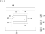
FIG. 2 is a perspective view which schematically shows anapparatus 100 for detecting defects of a battery cell according to an embodiment of the present disclosure.FIG. 3 is a front view of anapparatus 100 for detecting defects of a battery cell ofFIG. 2 . - The
apparatus 100 for detecting defects of a battery cell according to an embodiment of the present disclosure broadly includes: a magneticfield measuring section 110, asupport section 120 to which the magneticfield measuring section 110 is connected to fix and support the magneticfield measuring section 110, amounting section 130 on which thebattery cell 10 is placed, and aprocessing unit 140 and/or astorage unit 140. - The magnetic
field measuring section 110 is disposed near thebattery cell 10 and spaced away from thebattery cell 10 by a predetermined distance. A current is applied to thebattery cell 10, the current flows through thebattery cell 10 between apositive electrode lead 12 and anegative lead 12 of thebattery cell 10, and a magnetic field is induced therefrom. The magneticfield measuring section 110 measures the magnetic field induced from the current flowing through thebattery cell 10. Themain body 11 of thebattery cell 10 may be scanned, and themain body 11, the positive electrode lead 12 and thenegative electrode lead 12, and the positive electrode tab and the negative electrode tab may also be scanned as a whole. - In the
apparatus 100 for detecting defects of a battery cell according to an embodiment of the present disclosure, the magneticfield measuring section 110 can scan thebattery cell 10 in three dimensions at once. The magneticfield measuring section 110 may have, for example, a ⊏ shape or a square shape. More specifically, the magneticfield measuring section 110 includes afirst measuring member 111 that scans one side of thebattery cell 10, asecond measuring member 112 that scans the other side opposite to one side of thebattery cell 10, and one or two third measuringmembers 113 coupled between thefirst measuring member 111 and thesecond measuring member 112. - The
first measuring member 111 and the second measuringmember 112 may be arranged in parallel to each other. Further, onethird measuring member 113 may be coupled between one end of the first measuringmember 111 and one end of the second measuringmember 112. Thereby, the magneticfield measuring section 110 has a ⊏ shape. Alternatively, twothird measuring members 113 may be respectively coupled between one end of the first measuringmember 111 and one end of the second measuringmember 112, and coupled between the other end of the first measuringmember 111 and the other end of the second measuringmember 112. Thereby, the magneticfield measuring section 110 may have a square shape. - Each of the first measuring
member 111, the second measuringmember 112, and the third measuringmember 113 includes a scanner unit that scans a magnetic field on a surface facing thebattery cell 10. - The
first measuring member 111, the second measuringmember 112, and the third measuringmember 113 are integrated into one. More specifically, the first measuringmember 111, the second measuringmember 112, and the third measuringmember 113 may be formed integrally, or may be fabricated separately and then coupled together. Further, each of the first measuringmember 111, the second measuringmember 112 and the third measuringmember 113 may have a bar or rod shape. Alternatively, each of the first measuringmember 111, the second measuringmember 112 and the third measuringmember 113 may have a plate shape. In the former case, the magneticfield measuring section 110 may scan the magnetic field of thebattery cell 10 while moving along the longitudinal direction of thebattery cell 10. In the latter case, if each of the first measuringmember 111, the second measuringmember 112 and the third measuringmember 113 can cover thebattery cell 10, the magnetic field of thebattery cell 10 can be scanned at once without movement of the magneticfield measuring section 110. - For example, the first measuring
member 111 may scan the top surface of thebattery cell 10, and the second measuringmember 112 may scan the bottom surface of thebattery cell 10. Further, the third measuringmember 113 may scan both sides or one side of thebattery cell 10. However, the present disclosure is not limited to those set forth above, and when scanning with thebattery cell 10 upright, various modifications and changes are possible, for example, the first measuringmember 111 and the second measuringmember 112 can each scan both sides of thebattery cell 10, and the third measuringmember 113 can scan the top surface or bottom surface of thebattery cell 10. - In addition, the first measuring
member 111, the second measuringmember 112 and the third measuringmember 113 simultaneously scan thebattery cell 10, wherein the first measuringmember 111, the second measuringmember 112 and the third measuringmember 113 each individually generate magnetic field data from thebattery cells 10. In regard to magnetic field data, refer to those described later. - A
support section 120 is connected and fixed to the magneticfield measuring section 110 to support the magneticfield measuring section 110. In an exemplary embodiment ofFIG. 3 , the case where thesupport section 120 is connected to the first measuringmember 111 is illustrated, but the present disclosure is not limited thereto, and thesupport section 120 may be connected to at least one of the first measuringmember 111, the second measuringmember 112 and the third measuringmember 113. - When the magnetic
field measuring section 110 scans thebattery cell 10 while moving, thesupport section 120 may further include a driving member. The magneticfield measuring section 110 may scan thebattery cell 10 while moving in the longitudinal direction by the driving member included in thesupport section 120. - The
battery cell 10 is mounted on the mountingsection 130 including thesupport member 131. The mountingsection 130 broadly includes asupport member 131, apillar member 132, and a table 133. Thebattery cell 10 is placed on the plate-shapedsupport member 131. Thesupport member 131 may be located in the air at a predetermined distance upward from the bottom surface (e.g., table 133) by apillar member 132. Thesecond measuring member 112 of the magneticfield measuring section 110 is disposed on the bottom surface of thesupport member 131. Thereby, not only the first measuringmember 111 may be disposed on one side of thebattery cell 10, but also the second measuringmember 112 opposite thereto may be disposed on the other side opposite to the one side of thebattery cell 10. - Meanwhile, a
support member 131 is located between the second measuringmember 112 of the magneticfield measuring section 110 and thebattery cell 10. Thesupport member 131 has a low magnetic permeability (µ) so that thesupport member 131 has no influence on the magnetic field scanning of the second measuringmember 112, or the influence is minimized. - Data containing the magnetic field value of the
battery cell 10 measured by scanning in the magnetic field measuring section 110 (hereinafter referred to as "magnetic field data") is transmitted to aprocessing unit 140 and/or astorage unit 140 by wire or wirelessly. Theprocessing unit 140 and/or thestorage unit 140 may be provided separately, or may be integrated into one device. Theprocessing unit 140 and/or thestorage unit 140 may be, for example, a computer, a notebook, or various control devices applicable to the environment in which the invention is implemented and corresponding process. - Magnetic field data scanned by the magnetic
field measuring section 110 may be transmitted by wire through a data transmission line (not shown) provided on thesupport section 120 connected to the magneticfield measuring section 110. Alternatively, the magneticfield measuring section 110 or thesupport section 120 connected thereto may include a separate transceiver (not shown) to transmit the magnetic field data scanned by the magneticfield measuring section 110 wirelessly in real time (e.g., by repeating the method of scanning a certain portion of thebattery cell 10 and transmitting magnetic field data) or after scanning is completed as a whole. - Further, the magnetic field data transmitted from the magnetic
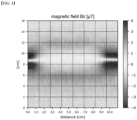
field measuring section 110 may be the magnetic field value itself, or may be a magnetic field image generated by the MFI method (e.g., seeFIG. 4 ). Alternatively, the magnetic field data transmitted from the magneticfield measuring section 110 is the magnetic field value itself, and theprocessing unit 140 may generate a magnetic field image using the MFI method. The unit of magnetic field value is T by way of example. - In regard to the
processing unit 140 and/or thestorage unit 140, refer to a method for detecting defects of a battery cell to be described later. - Next, a method for detecting defects of a battery cell according to an embodiment of the present disclosure will be described. The method for detecting defects of a battery cell is performed in the
processing unit 140 of theapparatus 100 for detecting defects of a battery cell. In addition, data can be transmitted/received, and stored in thestorage unit 140. That is, theprocessing unit 140 may perform a method for detecting defects of a battery cell in conjunction with thestorage unit 140. - First, a step (S110) of receiving magnetic field data from the magnetic
field measuring section 110 in theprocessing unit 140 and/or thestorage unit 140 is performed. In regard to magnetic field data transmission from the magneticfield measuring section 110, refer to the portion set forth above. - Further, a step (S120) of deriving magnetic field vector values for each of the plurality of sub-regions of the battery cell from the received magnetic field data is performed. The
processing unit 140 generates three-dimensional magnetic field vector values B=(Bx, By, Bz ) from the magnetic field data received from the magneticfield measuring section 110. The three-dimensional magnetic field vector values are magnetic field vector values at the x-axis position, y-axis position, and z-axis position of thebattery cell 10. The region of thebattery cell 10 can be divided into a plurality of sub-regions in three dimensions, and the magnetic field vector value B for each region can be generated. In theapparatus 100 for detecting defects of a battery cell of the present disclosure, since the magneticfield measuring section 110 scans thebattery cell 10 in three dimensions, such a three-dimensional magnetic field vector value B can be generated from the magnetic field data received from the magneticfield measuring section 110. - In regard to the generation of the magnetic field vector value B, for example, each magnetic field image generated from the first measuring
member 111, the second measuringmember 112 and the third measuringmember 113 of the magneticfield measuring section 110 is divided into a grid shape as shown inFIG. 4 , and then a three-dimensional vector value B can be derived from the corresponding magnetic field image value for each region. - Further, for example, a three-dimensional magnetic field vector value B can be generated by a method of weighting, summing and correcting from magnetic field data received from the first measuring
member 111, the second measuringmember 112 and the third measuringmember 113 of the magneticfield measuring section 110. For example, since the first measuringmember 111 and the second measuringmember 112 are located on both surfaces of thebattery cell 10 opposite to each other, a three-dimensional magnetic field vector value B can be derived by combining them. - However, the present disclosure is not limited to those set forth above, and any method that can generate a three-dimensional magnetic field vector value B = (Bx, By, Bz ) is sufficient.
- Next, a step(S130) of converting the derived magnetic field vector value into induced current data is performed. Since it is calculated from the magnetic field vector value, the induced current data becomes the induced current vector value (hereinafter referred to as "current vector value").
- Each of the three-dimensional magnetic field vector values B = (Bx, By, Bz ) at the x-axis, y-axis, and z-axis positions of the
battery cell 10 is converted into the current vector value I0= (I0x,I0y,I0z ). That is, the converted current value means the current value flowing at the corresponding x-axis, y-axis, and z-axis positions of thebattery cell 10. The process of converting a magnetic field into a current follows the Biot-Savart Law of the followingMathematical Equation 1.
battery cell 10 to the magnetic field measuring section 110). - In addition, when converting the corresponding magnetic field into current, the final current vector value I can be derived by multiplying the correction coefficient (α). This is a coefficient for correcting an error between the current value that actually flows in the relevant region of the
battery cell 10 and the current value that is induced from the magnetic field due to the relevant device or surrounding environment, etc. If correction is not necessary, the correction coefficient can be set to α = 1.
-
FIG. 5 shows an example of the final current vector value I. - In addition, the above process is performed from the magnetic field data transmitted from the first measuring
member 111, the second measuringmember 112 and the third measuringmember 113, respectively, to derive I D1, I D2, I D3 respectively. The I D1, I D2, I D3 mean currents derived from the magnetic field data of the first measuringmember 111, the second measuringmember 112 and the third measuringmember 113, respectively, in that order. - Next, a step (S140) of determining whether the induced current value corresponds to a current value in the normal range is performed. By comparing the derived induced current vector value with the current vector threshold, the presence or absence of an abnormal current can be determined.
- The presence or absence of an abnormal current is determined by comparing respective I D1, I D2, I D3 with the current threshold value ITH of a normal cell. That is, if it exceeds the current threshold ITH of a normal cell, it can be determined as a current abnormality. In addition, the current threshold of the normal cell may be set to an upper current threshold ITH-high and/or a lower current threshold ITH-low, respectively. In this case, if I is larger than the upper current threshold ITH-high or smaller than the lower current threshold ITH-low, it can be determined as current abnormality. Further, respective I D1, I D2, I D3 may be set by changing the current threshold ITH.
- Next, a step (S150) of detecting defects in the
battery cell 10 is performed. For example, if it is determined in step (S140) that it is an abnormal current, it may be determined that the correspondingbattery cell 10 is defective. In addition, for example, since thebattery cell 10 is divided into a plurality of sub-regions and a current vector value I is derived for each sub-region, the sub-region where an abnormal current is detected can be determined to be a defective region. - For reference, the defects of the
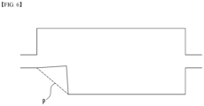
battery cell 10 may include, for example, folding of the electrode plate 11a or disconnection of the electrode plate 11a (e.g., perforation or tearing, etc.), defective application of electrode active material to the coated portion of the electrode plate 11a, disconnection of electrode tabs or electrode leads, or misalignment of a plurality of electrode plates stacked inside thebattery cell 10.FIG. 6 shows, as an example, a case where the electrode plate is folded at the folded portion P. - When detecting defects of the
battery cell 10 using theapparatus 100 for detecting defects of a battery cell and the method for detecting defects of a battery cell according to the present disclosure, it is possible to quickly determine the presence or absence of defects of thebattery cell 10 and/or the coupling portion of thebattery cell 10 as compared to the prior art. At the same time, it is possible to more accurately determine the presence or absence of defects of thebattery cell 10 and/or the coupling portion of thebattery cell 10. Thereby, reliability of the quality of the produced battery cells can be secured. - Although the invention has been described in detail above with reference to preferred embodiments thereof, it will be appreciated by those skilled in the art that the scope of the present disclosure is not limited thereto, and various modifications and improvements can be made in these embodiments without departing from the principles and sprit of the invention, the scope of which is defined in the appended claims and their equivalents.
-
- 10: battery cell
- 11: main body
- 12: electrode lead
- 100: apparatus for detecting defects of a battery cell
- 110: magnetic field measuring section
- 111: first measuring member
- 112: second measuring member
- 113: third measuring member
- 120: support section
- 130: mounting section
- 131: support member
- 132: pillar member
- 133: table
- 140: processing unit/storage unit
Claims (15)
- An apparatus for detecting defects of a battery cell, comprising:a magnetic field measuring section that measures the magnetic field generated by the current flowing through the battery cell;a support section that supports the magnetic field measuring section; anda mounting section on which the battery cell is placed,wherein the magnetic field measuring section comprises a first measuring member that scans one side of the battery cell, a second measuring member that scans the other side of the battery cell opposite to the one side, and a third measuring member that is coupled between the first measuring member and the second measuring member, andwherein the first measuring member, the second measuring member and the third measuring member are integrated.
- The apparatus for detecting defects of a battery cell according to claim 1, wherein:
the magnetic field measuring section includes the first measuring member, the second measuring member, and the third measuring member, and simultaneously scans the top surface, bottom surface, and side surface of the battery cell. - The apparatus for detecting defects of a battery cell according to claim 1, wherein:
one third measuring member is provided, and connects one end of the first measuring member and one end of the second measuring member. - The apparatus for detecting defects of a battery cell according to claim 1, wherein:
two third measuring members are provided, wherein one connects one end of the first measuring member and one end of the second measuring member, and the other connects the other end of the first measuring member and the other end of the second measuring member. - The apparatus for detecting defects of a battery cell according to claim 1, wherein:the mounting section is a support member having a plate shape on which the battery cell is placed, and includes the support member disposed in the air at a predetermined distance upward from a bottom surface, andthe second measuring member is disposed below the support member.
- The apparatus for detecting defects of a battery cell according to claim 1, wherein:
the support member has a low magnetic permeability (µ) so that the influence of the support member on the magnetic field scanning of the second measuring member is minimized. - The apparatus for detecting defects of a battery cell according to claim 1,
further comprising a processing unit that converts measured magnetic field data to determine the presence or absence of defects in the battery cell or a defective portion of the battery cell. - The apparatus for detecting defects of a battery cell according to claim 1, wherein:each of the first measuring member, the second measuring member and the third measuring member has a bar or rod shape, andthe magnetic field measuring section moves in the longitudinal direction of the battery cell, thereby scanning the battery cell.
- The apparatus for detecting defects of a battery cell according to claim 1, wherein:
the first measuring member, the second measuring member and the third measuring member each individually generate magnetic field data. - The apparatus for detecting defects of a battery cell according to claim 9, wherein:
a three-dimensional magnetic field vector value is generated from the magnetic field data individually generated from each of the first measuring member, the second measuring member, and the third measuring member. - The apparatus for detecting defects of a battery cell according to claim 1, wherein:
the magnetic field data is a magnetic field image(MFI). - The apparatus for detecting defects of a battery cell according to claim 1, wherein:
the type of defects detected above includes at least one of: a folded portion of an electrode plate of the battery cell, a disconnection portion of the electrode plate, a portion where the electrode active material is unevenly applied to the coated portion of the electrode plate, a disconnection portion of an electrode lead or electrode tab of the battery cell, and a portion where the stacked electrode plates are misaligned. - A method for detecting defects of a battery cell, the method comprising the steps of:receiving magnetic field data measured by a magnetic field measuring section;deriving a three-dimensional magnetic field vector value for each of a plurality of sub-regions of the battery cell from the received magnetic field data;converting the derived magnetic field vector value into a three-dimensional induced current vector value;determining whether the induced current value corresponds to a current value in a normal range by comparing the induced current vector value with a predetermined current vector threshold; anddetecting the presence or absence of defects in the battery cell or a defective portion of the battery cell.
- The method for detecting defects of a battery cell according to claim 13, wherein:
the converting the derived magnetic field vector value into an induced current vector value comprises multiplying the induced current vector value by a correction coefficient. - The method for detecting defects of a battery cell according to claim 13, wherein:
the determining whether the induced current value corresponds to a current value in a normal range comprises determining that that there is a current abnormality in the battery cell if the induced current vector value is larger than a predetermined upper limit current vector threshold or if the induced current vector value is smaller than a predetermined lower limit current vector threshold.
Applications Claiming Priority (2)
| Application Number | Priority Date | Filing Date | Title |
|---|---|---|---|
| KR1020220180417A KR20240098558A (en) | 2022-12-21 | 2022-12-21 | An apparatus for detecting defeats of a battery cell and a method for detecting defeats of a battery cell |
| PCT/KR2023/021005 WO2024136410A1 (en) | 2022-12-21 | 2023-12-19 | Apparatus for detecting defects of battery cell and method for detecting defects of battery cell |
Publications (2)
| Publication Number | Publication Date |
|---|---|
| EP4579869A1 true EP4579869A1 (en) | 2025-07-02 |
| EP4579869A4 EP4579869A4 (en) | 2026-02-25 |
Family
ID=91589546
Family Applications (1)
| Application Number | Title | Priority Date | Filing Date |
|---|---|---|---|
| EP23907693.8A Pending EP4579869A4 (en) | 2022-12-21 | 2023-12-19 | DEVICE FOR DETECTING DEFECT IN A BATTERY CELL AND METHOD FOR DETECTING DEFECT IN A BATTERY CELL |
Country Status (6)
| Country | Link |
|---|---|
| US (1) | US20260092982A1 (en) |
| EP (1) | EP4579869A4 (en) |
| JP (1) | JP2025533257A (en) |
| KR (1) | KR20240098558A (en) |
| CN (1) | CN119998980A (en) |
| WO (1) | WO2024136410A1 (en) |
Family Cites Families (11)
| Publication number | Priority date | Publication date | Assignee | Title |
|---|---|---|---|---|
| JP5240306B2 (en) * | 2011-02-14 | 2013-07-17 | パルステック工業株式会社 | Solar cell inspection equipment |
| JP5257494B2 (en) * | 2011-08-02 | 2013-08-07 | パルステック工業株式会社 | Secondary battery evaluation device and evaluation method |
| KR20250024862A (en) * | 2013-03-14 | 2025-02-19 | 캘리포니아 인스티튜트 오브 테크놀로지 | Method for abnormality detection, system for detecting abnormality, and energy storage system |
| US11921067B2 (en) * | 2015-04-17 | 2024-03-05 | New York University | System and method for magnetic resonance mapping of physical and chemical changes in conducting structures |
| KR102151175B1 (en) * | 2018-07-06 | 2020-09-03 | 주식회사 정안시스템 | Electrode damage inspection electrode damage method of pouch type secondary battery |
| KR102497448B1 (en) * | 2019-02-14 | 2023-02-08 | 주식회사 엘지에너지솔루션 | Apparatus and method for determining error of a battery cell |
| KR102023739B1 (en) * | 2019-04-17 | 2019-09-20 | 주식회사 엘지화학 | Inner crack detection device for secondary battery using eddy current |
| JP2020187951A (en) * | 2019-05-16 | 2020-11-19 | トヨタ自動車株式会社 | Battery inspection method, battery inspection device and battery |
| KR102773409B1 (en) * | 2019-08-16 | 2025-02-27 | 주식회사 엘지에너지솔루션 | An eddy current sensor with improved crack detection and eddy current inspection device comprising the same |
| CN114746763B (en) * | 2019-11-28 | 2026-02-27 | 国立大学法人神户大学 | External field response distribution visualization device and method |
| KR102700097B1 (en) * | 2021-05-21 | 2024-08-28 | (주)오성하이텍 | Quality Inspection Device and Method of Pouch Type Secondary Battery Cells |
-
2022
- 2022-12-21 KR KR1020220180417A patent/KR20240098558A/en active Pending
-
2023
- 2023-12-19 US US19/120,211 patent/US20260092982A1/en active Pending
- 2023-12-19 CN CN202380070404.5A patent/CN119998980A/en active Pending
- 2023-12-19 WO PCT/KR2023/021005 patent/WO2024136410A1/en not_active Ceased
- 2023-12-19 EP EP23907693.8A patent/EP4579869A4/en active Pending
- 2023-12-19 JP JP2025521155A patent/JP2025533257A/en active Pending
Also Published As
| Publication number | Publication date |
|---|---|
| WO2024136410A1 (en) | 2024-06-27 |
| EP4579869A4 (en) | 2026-02-25 |
| KR20240098558A (en) | 2024-06-28 |
| CN119998980A (en) | 2025-05-13 |
| JP2025533257A (en) | 2025-10-03 |
| US20260092982A1 (en) | 2026-04-02 |
Similar Documents
| Publication | Publication Date | Title |
|---|---|---|
| KR102294189B1 (en) | Inspection device to detect welding status of missing or folding tab of battery electrode | |
| KR102909368B1 (en) | System and method for battery module welding inspection | |
| KR102151175B1 (en) | Electrode damage inspection electrode damage method of pouch type secondary battery | |
| US11543387B2 (en) | Method for characterizing a weld | |
| KR102909370B1 (en) | Electrode alignment inspection device and method | |
| KR102303643B1 (en) | Inspection device and method for detecting air void at the lead film of battery | |
| CN114571167B (en) | Method for producing a battery element | |
| KR102036000B1 (en) | Apparatus for Testing of Touch Electrode of Touch Screen Panel | |
| EP4113113B1 (en) | Big data-based battery inspection method | |
| KR20210002965A (en) | A Noncontact Type of an X-Ray Investigating Apparatus and a Method for Investigating an Article with the Same | |
| JP2016507060A (en) | Method and apparatus for improving analysis by SAFT method during irregular measurement | |
| EP3220139B1 (en) | Eddy-current flaw detection device and eddy-current flaw detection method | |
| US20260092982A1 (en) | An apparatus for detecting defects of a battery cell and a method for detecting defects of a battery cell | |
| EP1217357B1 (en) | Inspection apparatus and method for electrode plate-connected structure for secondary cell | |
| EP2239564A1 (en) | Welding inspection method and welding inspection apparatus | |
| KR100956873B1 (en) | Inspection system using x-ray | |
| JP6951478B2 (en) | Antenna inspection method including multiple radiating elements, and antenna inspection system including multiple radiating elements | |
| DE102012215120B4 (en) | EVALUATION DEVICE, METHOD AND TEST SYSTEM FOR TESTING ELECTRO-CHEMICAL CELL ARRANGEMENTS | |
| US20240110892A1 (en) | Apparatus for Automatically Inspecting Welding State | |
| JP5020285B2 (en) | Nondestructive inspection apparatus and nondestructive inspection method | |
| KR20250060300A (en) | X-ray system | |
| KR20250049736A (en) | An apparatus for detecting defeats of a battery cell and a method for detecting defeats of a battery cell | |
| CN118215819A (en) | Apparatus and method for measuring sealing gap of secondary battery | |
| CN114740084A (en) | Detection method and system for steel surface coating | |
| EP4414121A1 (en) | Battery cell welded part inspection apparatus, and battery cell welded part inspection method using same |
Legal Events
| Date | Code | Title | Description |
|---|---|---|---|
| STAA | Information on the status of an ep patent application or granted ep patent |
Free format text: STATUS: THE INTERNATIONAL PUBLICATION HAS BEEN MADE |
|
| PUAI | Public reference made under article 153(3) epc to a published international application that has entered the european phase |
Free format text: ORIGINAL CODE: 0009012 |
|
| STAA | Information on the status of an ep patent application or granted ep patent |
Free format text: STATUS: REQUEST FOR EXAMINATION WAS MADE |
|
| 17P | Request for examination filed |
Effective date: 20250327 |
|
| AK | Designated contracting states |
Kind code of ref document: A1 Designated state(s): AL AT BE BG CH CY CZ DE DK EE ES FI FR GB GR HR HU IE IS IT LI LT LU LV MC ME MK MT NL NO PL PT RO RS SE SI SK SM TR |
|
| A4 | Supplementary search report drawn up and despatched |
Effective date: 20260128 |
|
| RIC1 | Information provided on ipc code assigned before grant |
Ipc: H01M 10/42 20060101AFI20260122BHEP Ipc: G01N 27/82 20060101ALI20260122BHEP Ipc: H01M 10/48 20060101ALI20260122BHEP |
|
| DAV | Request for validation of the european patent (deleted) | ||
| DAX | Request for extension of the european patent (deleted) |