EP4579768A1 - Electrochemical device and electronic device - Google Patents
Electrochemical device and electronic device Download PDFInfo
- Publication number
- EP4579768A1 EP4579768A1 EP22960024.2A EP22960024A EP4579768A1 EP 4579768 A1 EP4579768 A1 EP 4579768A1 EP 22960024 A EP22960024 A EP 22960024A EP 4579768 A1 EP4579768 A1 EP 4579768A1
- Authority
- EP
- European Patent Office
- Prior art keywords
- positive electrode
- lithium
- material layer
- electrode plate
- current collector
- Prior art date
- Legal status (The legal status is an assumption and is not a legal conclusion. Google has not performed a legal analysis and makes no representation as to the accuracy of the status listed.)
- Pending
Links
Images


Classifications
-
- H—ELECTRICITY
- H01—ELECTRIC ELEMENTS
- H01M—PROCESSES OR MEANS, e.g. BATTERIES, FOR THE DIRECT CONVERSION OF CHEMICAL ENERGY INTO ELECTRICAL ENERGY
- H01M10/00—Secondary cells; Manufacture thereof
- H01M10/05—Accumulators with non-aqueous electrolyte
- H01M10/052—Li-accumulators
- H01M10/0525—Rocking-chair batteries, i.e. batteries with lithium insertion or intercalation in both electrodes; Lithium-ion batteries
-
- H—ELECTRICITY
- H01—ELECTRIC ELEMENTS
- H01M—PROCESSES OR MEANS, e.g. BATTERIES, FOR THE DIRECT CONVERSION OF CHEMICAL ENERGY INTO ELECTRICAL ENERGY
- H01M4/00—Electrodes
- H01M4/02—Electrodes composed of, or comprising, active material
- H01M4/62—Selection of inactive substances as ingredients for active masses, e.g. binders, fillers
-
- H—ELECTRICITY
- H01—ELECTRIC ELEMENTS
- H01M—PROCESSES OR MEANS, e.g. BATTERIES, FOR THE DIRECT CONVERSION OF CHEMICAL ENERGY INTO ELECTRICAL ENERGY
- H01M10/00—Secondary cells; Manufacture thereof
- H01M10/05—Accumulators with non-aqueous electrolyte
- H01M10/058—Construction or manufacture
- H01M10/0587—Construction or manufacture of accumulators having only wound construction elements, i.e. wound positive electrodes, wound negative electrodes and wound separators
-
- H—ELECTRICITY
- H01—ELECTRIC ELEMENTS
- H01M—PROCESSES OR MEANS, e.g. BATTERIES, FOR THE DIRECT CONVERSION OF CHEMICAL ENERGY INTO ELECTRICAL ENERGY
- H01M4/00—Electrodes
- H01M4/02—Electrodes composed of, or comprising, active material
- H01M4/13—Electrodes for accumulators with non-aqueous electrolyte, e.g. for lithium-accumulators; Processes of manufacture thereof
-
- H—ELECTRICITY
- H01—ELECTRIC ELEMENTS
- H01M—PROCESSES OR MEANS, e.g. BATTERIES, FOR THE DIRECT CONVERSION OF CHEMICAL ENERGY INTO ELECTRICAL ENERGY
- H01M4/00—Electrodes
- H01M4/02—Electrodes composed of, or comprising, active material
- H01M4/36—Selection of substances as active materials, active masses, active liquids
- H01M4/38—Selection of substances as active materials, active masses, active liquids of elements or alloys
- H01M4/386—Silicon or alloys based on silicon
-
- H—ELECTRICITY
- H01—ELECTRIC ELEMENTS
- H01M—PROCESSES OR MEANS, e.g. BATTERIES, FOR THE DIRECT CONVERSION OF CHEMICAL ENERGY INTO ELECTRICAL ENERGY
- H01M4/00—Electrodes
- H01M4/02—Electrodes composed of, or comprising, active material
- H01M4/62—Selection of inactive substances as ingredients for active masses, e.g. binders, fillers
- H01M4/621—Binders
- H01M4/622—Binders being polymers
- H01M4/623—Binders being polymers fluorinated polymers
-
- H—ELECTRICITY
- H01—ELECTRIC ELEMENTS
- H01M—PROCESSES OR MEANS, e.g. BATTERIES, FOR THE DIRECT CONVERSION OF CHEMICAL ENERGY INTO ELECTRICAL ENERGY
- H01M4/00—Electrodes
- H01M4/02—Electrodes composed of, or comprising, active material
- H01M4/64—Carriers or collectors
- H01M4/66—Selection of materials
- H01M4/661—Metal or alloys, e.g. alloy coatings
-
- H—ELECTRICITY
- H01—ELECTRIC ELEMENTS
- H01M—PROCESSES OR MEANS, e.g. BATTERIES, FOR THE DIRECT CONVERSION OF CHEMICAL ENERGY INTO ELECTRICAL ENERGY
- H01M4/00—Electrodes
- H01M4/02—Electrodes composed of, or comprising, active material
- H01M4/64—Carriers or collectors
- H01M4/66—Selection of materials
- H01M4/661—Metal or alloys, e.g. alloy coatings
- H01M4/662—Alloys
-
- H—ELECTRICITY
- H01—ELECTRIC ELEMENTS
- H01M—PROCESSES OR MEANS, e.g. BATTERIES, FOR THE DIRECT CONVERSION OF CHEMICAL ENERGY INTO ELECTRICAL ENERGY
- H01M4/00—Electrodes
- H01M4/02—Electrodes composed of, or comprising, active material
- H01M4/64—Carriers or collectors
- H01M4/66—Selection of materials
- H01M4/665—Composites
- H01M4/667—Composites in the form of layers, e.g. coatings
-
- H—ELECTRICITY
- H01—ELECTRIC ELEMENTS
- H01M—PROCESSES OR MEANS, e.g. BATTERIES, FOR THE DIRECT CONVERSION OF CHEMICAL ENERGY INTO ELECTRICAL ENERGY
- H01M10/00—Secondary cells; Manufacture thereof
- H01M10/05—Accumulators with non-aqueous electrolyte
- H01M10/056—Accumulators with non-aqueous electrolyte characterised by the materials used as electrolytes, e.g. mixed inorganic/organic electrolytes
- H01M10/0564—Accumulators with non-aqueous electrolyte characterised by the materials used as electrolytes, e.g. mixed inorganic/organic electrolytes the electrolyte being constituted of organic materials only
- H01M10/0566—Liquid materials
-
- H—ELECTRICITY
- H01—ELECTRIC ELEMENTS
- H01M—PROCESSES OR MEANS, e.g. BATTERIES, FOR THE DIRECT CONVERSION OF CHEMICAL ENERGY INTO ELECTRICAL ENERGY
- H01M10/00—Secondary cells; Manufacture thereof
- H01M10/05—Accumulators with non-aqueous electrolyte
- H01M10/056—Accumulators with non-aqueous electrolyte characterised by the materials used as electrolytes, e.g. mixed inorganic/organic electrolytes
- H01M10/0564—Accumulators with non-aqueous electrolyte characterised by the materials used as electrolytes, e.g. mixed inorganic/organic electrolytes the electrolyte being constituted of organic materials only
- H01M10/0566—Liquid materials
- H01M10/0567—Liquid materials characterised by the additives
-
- H—ELECTRICITY
- H01—ELECTRIC ELEMENTS
- H01M—PROCESSES OR MEANS, e.g. BATTERIES, FOR THE DIRECT CONVERSION OF CHEMICAL ENERGY INTO ELECTRICAL ENERGY
- H01M4/00—Electrodes
- H01M4/02—Electrodes composed of, or comprising, active material
- H01M2004/021—Physical characteristics, e.g. porosity, surface area
-
- H—ELECTRICITY
- H01—ELECTRIC ELEMENTS
- H01M—PROCESSES OR MEANS, e.g. BATTERIES, FOR THE DIRECT CONVERSION OF CHEMICAL ENERGY INTO ELECTRICAL ENERGY
- H01M4/00—Electrodes
- H01M4/02—Electrodes composed of, or comprising, active material
- H01M2004/026—Electrodes composed of, or comprising, active material characterised by the polarity
- H01M2004/028—Positive electrodes
-
- H—ELECTRICITY
- H01—ELECTRIC ELEMENTS
- H01M—PROCESSES OR MEANS, e.g. BATTERIES, FOR THE DIRECT CONVERSION OF CHEMICAL ENERGY INTO ELECTRICAL ENERGY
- H01M2300/00—Electrolytes
- H01M2300/0017—Non-aqueous electrolytes
- H01M2300/0025—Organic electrolyte
-
- H—ELECTRICITY
- H01—ELECTRIC ELEMENTS
- H01M—PROCESSES OR MEANS, e.g. BATTERIES, FOR THE DIRECT CONVERSION OF CHEMICAL ENERGY INTO ELECTRICAL ENERGY
- H01M2300/00—Electrolytes
- H01M2300/0017—Non-aqueous electrolytes
- H01M2300/0025—Organic electrolyte
- H01M2300/0028—Organic electrolyte characterised by the solvent
- H01M2300/0034—Fluorinated solvents
-
- H—ELECTRICITY
- H01—ELECTRIC ELEMENTS
- H01M—PROCESSES OR MEANS, e.g. BATTERIES, FOR THE DIRECT CONVERSION OF CHEMICAL ENERGY INTO ELECTRICAL ENERGY
- H01M50/00—Constructional details or processes of manufacture of the non-active parts of electrochemical cells other than fuel cells, e.g. hybrid cells
- H01M50/10—Primary casings; Jackets or wrappings
- H01M50/102—Primary casings; Jackets or wrappings characterised by their shape or physical structure
- H01M50/105—Pouches or flexible bags
-
- Y—GENERAL TAGGING OF NEW TECHNOLOGICAL DEVELOPMENTS; GENERAL TAGGING OF CROSS-SECTIONAL TECHNOLOGIES SPANNING OVER SEVERAL SECTIONS OF THE IPC; TECHNICAL SUBJECTS COVERED BY FORMER USPC CROSS-REFERENCE ART COLLECTIONS [XRACs] AND DIGESTS
- Y02—TECHNOLOGIES OR APPLICATIONS FOR MITIGATION OR ADAPTATION AGAINST CLIMATE CHANGE
- Y02E—REDUCTION OF GREENHOUSE GAS [GHG] EMISSIONS, RELATED TO ENERGY GENERATION, TRANSMISSION OR DISTRIBUTION
- Y02E60/00—Enabling technologies; Technologies with a potential or indirect contribution to GHG emissions mitigation
- Y02E60/10—Energy storage using batteries
Definitions
- the type of aluminum foil is not particularly limited in this application and may be any well-known aluminum foil in the art, provided that the objectives of this application can be achieved.
- Dv50 of the inorganic oxide particles is 0.1 ⁇ m to 30 ⁇ m
- Dv50 of the elemental nonmetal is 0.1 ⁇ m to 10 ⁇ m.
- Dv50 of the inorganic oxide is 0.1 ⁇ m, 1 ⁇ m, 5 ⁇ m, 10 ⁇ m, 15 ⁇ m, 20 ⁇ m, 25 ⁇ m, or 30 ⁇ m, or any value between any two of the foregoing values
- Dv50 of the elemental nonmetal is 0.1 ⁇ m, 1 ⁇ m, 5 ⁇ m, or 10 ⁇ m, or any value between any two of the foregoing values.
- the average particle sizes Dv50 of the inorganic oxide and elemental nonmetal being controlled within the foregoing ranges, it is more conducive to controlling the thickness of the inactive material layer to be within an appropriate range, allowing the inactive material layer to physically isolate the electrolyte from the positive electrode current collector, in order to lower the possibility of generation of by-products by reactions between the electrolyte and the positive electrode current collector and reduce the percentage of the by-products.
- the risk of the by-products accumulating in a specific zone or another zone of the positive electrode plate is reduced. Therefore, the risks of abnormality in the positive electrode plate and lithium precipitation in the negative electrode plate after the electrochemical apparatus has undergone charge-discharge cycles are lowered, thereby lowering the risk of failure of the electrochemical apparatus during the charge-discharge cycles.
- Dv50 represents a particle size of the inorganic oxide or elemental nonmetal at a cumulative volume of 50% in a volume-based particle size distribution as measured by starting from small particle sizes.
- the inactive material layer further includes an inactive material layer binder
- the inactive material layer binder includes at least one of polytetrafluoroethylene, chloroprene rubber, nitrile rubber, styrene-butadiene rubber, carboxylated rubber, chlorosulfonated polyethylene rubber, phenolic resin, epoxy resin, or silicone resin.
- a mass ratio of the inactive material to the inactive material layer binder is (70 to 98):(2 to 30).
- a mass ratio of the inactive material to the binder is 70:30, 75:25, 80:20, 85:15, 90:10, 95:5, or 98:2, or any value between any two of the foregoing values.
- the inactive material layer binder and the mass ratio of the inactive material layer to the the inactive material layer binder in the inactive material layer being controlled within the foregoing range, it is more conducive to preparing an inactive material layer with excellent isolation effect to isolate the electrolyte from the positive electrode current collector, further lowering the possibility of contact between the electrolyte and the positive electrode current collector and further reducing the percentage of the by-products generated by reactions between the electrolyte and the positive electrode current collector.
- the risk of the by-products accumulating in a specific zone or another zone of the positive electrode plate is reduced.
- the risks of abnormality in the positive electrode plate and lithium precipitation in the negative electrode plate after the electrochemical apparatus has undergone charge-discharge cycles are lowered, thereby lowering the risk of failure of the electrochemical apparatus during the charge-discharge cycles.
- the fluorine-containing compound includes a fluorine-containing additive, and a mass percentage of the fluorine-containing additive in the electrolyte is c%, with 0.1 ⁇ c ⁇ 40.
- a value of c is 0.1, 2.0, 5.0, 10.0, 15.0, 20.0, 25.0, 30.0, 35.0, or 40.0, or any value between any two of the foregoing values.
- the protective ability of the electrolyte on the negative electrode plate can be enhanced, and a uniform and dense protective film can be formed on the surface of the negative electrode plate, thereby improving the cycling performance of the electrochemical apparatus while reducing the percentage of fluorinated silicon compounds generated by reactions between HF in the electrolyte and element silicon in the positive electrode current collector. In this way, the risk of abnormality in the positive electrode plate is lowered, thereby lowering the risk of failure of the electrochemical apparatus during the charge-discharge cycles.
- a thickness of the inactive material layer is b ⁇ m, with 3 ⁇ b ⁇ 20.
- a value of b is 3, 4, 6, 8, 10, 12, 14, 16, 18, or 20, or any value between any two of the foregoing values.
- the inactive material layer With the thickness of the inactive material layer being controlled within the foregoing range and without increasing the volume of the electrochemical apparatus and affecting the energy density of the electrochemical apparatus, it is more conducive for the inactive material layer to act as an inert layer between the electrolyte and the positive electrode current collector to isolate the electrolyte from the positive electrode current collector, lowering the possibility of contact between the electrolyte and the positive electrode current collector and reducing the percentage of the by-products generated by reactions between the electrolyte and the positive electrode current collector. As a result, the risk of the by-products accumulating in a specific zone or another zone of the positive electrode plate is reduced.
- the risks of abnormality in the positive electrode plate and lithium precipitation in the negative electrode plate after the electrochemical apparatus has undergone charge-discharge cycles are lowered, thereby lowering the risk of failure of the electrochemical apparatus during the charge-discharge cycles.
- this can make the roll pressing device act on the inactive material layer in the roll pressing process after the electrode plate has been coated, lowering the risk of breakage of the positive electrode plate caused by the roll pressing device directly transitioning to the positive electrode current collector from the positive electrode active material layer.
- the method of controlling the thickness of the inactive material layer is not particularly limited in this application, provided that the objectives of this application can be achieved. For example, this is implemented by controlling Dv50 of the inactive material or the coating weight of slurry on the inactive material layer.
- 0.003 ⁇ a/b ⁇ 0.025. In some embodiments of this application, 0.003 ⁇ a/b ⁇ 0.02.
- the value of a/ b is 0.003, 0.005, 0.01, 0.015, 0.02, or 0.025, or any value between any two of the foregoing values.
- the thickness of the inactive material allows the inactive material to fully exert its isolation effect, isolating the electrolyte from the positive electrode current collector without increasing the volume of the electrochemical apparatus and affecting the energy density of the electrochemical apparatus, so that the possibility of generation of by-products by reactions between the electrolyte and the positive electrode current collector is lowered, the percentage of the by-products is reduced, and the risk of by-products accumulating in a specific area or another area of the positive electrode plate is lowered. Therefore, this is more conducive to lowering the risk of failure of the electrochemical apparatus during the charge-discharge cycles.
- the fluorine-containing additive includes at least one of fluoroethylene carbonate (FEC), difluoromethyl ethylene carbonate (DFEC), bis(difluoromethyl) ethylene carbonate, bis(trifluoromethyl) ethylene carbonate, bis(2-fluoroethyl) ethylene carbonate, bis(2,2-difluoroethyl) ethylene carbonate, bis(2,2,2-trifluoroethyl) ethylene carbonate, 2-fluoroethylmethylethylene carbonate, 2,2-difluoroethyl methyl ethylene carbonate, or 2,2,2-trifluoroethyl methyl ethylene carbonate.
- FEC fluoroethylene carbonate
- DFEC difluoromethyl ethylene carbonate
- the use of the foregoing type of fluorine-containing additive is more conducive to weakening the ability of the positive electrode plate to oxidize the electrolyte and forming a uniform and dense protective film on surfaces of the positive electrode plate and negative electrode plate to protect the positive electrode plate and negative electrode plate.
- the fluorine-containing substance includes a fluorine-containing lithium salt
- the fluorine-containing lithium salt includes at least one of lithium hexafluorophosphate, lithium difluorophosphate (LiPF 2 ), lithium bis(trifluoromethanesulfonyl)imide (LiTFSI), lithium bis(fluorosulfonyl)imide (LiTSI), lithium tetrafluoroborate (LiBF 4 ), lithium difluoro(oxalato)borate (LiBF 2 (C 2 O 4 ), LiDFOB), lithium hexafluoroantimonate (LiSbF 6 ), lithium hexafluoroarsenate (LiAsF 6 ), lithium perfluorobutanesulfonate (LiC 4 F 9 SO 3 ), lithium bis(sulfonyl)imide (LiN(C x F 2x+1 SO 2 )(C y F 2y+1
- the addition of the fluorine-containing lithium salt is more conducive to providing high ionic conductivity for faster lithium ion transport.
- the fluorine-containing lithium salt includes at least one of LiPF 6 , LiTFSI, or LiTSI, and this is more conducive to lowering the production cost of the electrochemical apparatus.
- the mass percentage of the fluorine-containing lithium salt in the electrolyte is not particularly limited in this application, provided that the objectives this application can be achieved. For example, the mass percentage of the fluorine-containing lithium salt in the electrolyte is 8% to 20%.
- the electrode assembly has a stacked structure.
- the electrode assembly has a wound structure
- the positive electrode current collector 10 further includes a double-sided region 40
- the double-sided region 40 is sequentially connected to the single-sided region 30 in a winding direction W.
- a positive electrode active material layer 20 is provided on both the first surface 10a and the second surface 10b of the double-sided region 40.
- the thickness of the positive electrode current collector is not particularly limited in this application, provided that the objectives of this application can be achieved.
- the thickness of the positive electrode current collector is 8 ⁇ m to 20 ⁇ m.
- the compressed density of the cold pressed positive electrode plate and negative electrode plate is not particularly limited in this application, provided that the objectives of this application can be achieved.
- the compacted density of the positive electrode plate and negative electrode plate after cold pressing is 3.9 g/cm 3 to 4.3 g/cm 3 .
- the thickness of the positive electrode active material layer is not particularly limited in this application, provided that the objectives of this application can be achieved.
- the thickness of the positive electrode active material layer is 30 ⁇ m to 120 ⁇ m.
- the types of the conductive agent, stabilizer, and binder in the negative electrode active material layer is not particularly limited in this application, provided that the objectives of this application can be achieved.
- the mass ratio of the negative electrode active material, conductive agent, stabilizer, and binder in the negative electrode active material layer is not particularly limited in this application, provided that the objectives of this application can be achieved.
- the mass ratio of the negative electrode active material, conductive agent, stabilizer, and binder in the negative electrode active material layer is (97 to 98):(0.5 to 1.5):(0.5 to 1.5):(1.0 to 1.9).
- Thicknesses of the negative electrode current collector and the negative electrode active material layer are not particularly limited in this application, provided that the objectives of this application can be achieved.
- the thickness of the negative electrode current collector is 5 ⁇ m to 20 ⁇ m
- the thickness of the negative electrode active material layer is 30 ⁇ m to 120 ⁇ m.
- the electrolyte of this application further includes a non-aqueous solvent.
- the non-aqueous solvent is not particularly limited in this application, provided that the objective of this application can be achieved.
- the non-aqueous solvent may include but is not limited to at least one of dimethyl carbonate (DMC), diethyl carbonate (DEC), dipropyl carbonate (DPC), methyl propyl carbonate (MPC), ethyl propyl carbonate (EPC), methyl ethyl carbonate (MEC), ethylene carbonate (EC), propylene carbonate (PC), butylene carbonate (BC), ethyl acetate, n-propyl acetate, tert-butyl acetate, methyl propionate, ethyl propionate, or propyl propionate.
- DMC dimethyl carbonate
- DEC diethyl carbonate
- DPC dipropyl carbonate
- MPC methyl propyl carbonate
- EPC e
- Table 1 a (%) Inactive material Dv50 of inorganic oxide ( ⁇ m) Dv50 of elemental nonmetal ( ⁇ m) Inactive material layer binder N Abnormal appearance in positive electrode plate? Percentage of Si in abnormal zone of positive electrode plate (wt%) Abnormalities in preparation process of positive electrode plate?
- the mass percentage a% of element silicon in the positive electrode current collector usually affects the probability of failure of the lithium-ion battery during the charge-discharge cycles. From Examples 1-1 to 1-3 and Comparative examples 2 and 3, it can be seen that with the use of the lithium-ion battery with a mass percentage a% of element silicon in the positive electrode current collector within the range in this application, there is no abnormal appearance on the positive electrode plate, indicating that the risk of failure of the lithium-ion battery during the charge-discharge cycles is lowered, and there is only the problem of significant fluctuations in laser positioning, without affecting the use performance of the positive electrode plate.
- the type of the inactive material usually affects the probability of failure of the lithium-ion battery during the charge-discharge cycles. From Examples 1-2, 1-4, 1-5, and 1-7, it can be seen that with the use of the lithium-ion battery for which the type of inactive material is within the range in this application, there is no abnormal appearance on the positive electrode plate, indicating that the risk of failure of the lithium-ion battery during the charge-discharge cycles is lowered, and there are no abnormalities in the preparation process of the positive electrode plate or there is only the problem of significant fluctuations in laser positioning, without affecting the use performance of the positive electrode plate.
- the mass ratio of the inactive material to the inactive material layer binder usually affects the probability of failure of the lithium-ion battery during the charge-discharge cycles. From Examples 1-2, 1-8, and 1-9, it can be seen that with the use of the lithium-ion battery for which the mass ratio of the inactive material to the inactive material layer binder is within the range in this application, there is no abnormal appearance on the positive electrode plate, indicating that the risk of failure of the lithium-ion battery during the charge-discharge cycles is lowered, and there are no abnormalities in the preparation process of the positive electrode plate, without affecting the use performance of the positive electrode plate.
- Example 1-2 0.06 3 0.02 FEC 38 12.7 No - N/A
- Example 2-1 0.06 10 0.006 FEC 38 3.8 No - N/A
- Example 2-2 0.06 20 0.003 FEC 38 1.9 No - N/A
- Example 2-3 0.075 3 0.025 FEC 38 12.7 Yes 1.5 N/A
- Example 2-4 0.06 3 0.02 FEC 0.3 0.1 No - N/A
- Example 2-5 0.06 3 0.02 FEC 20 6.7 No - N/A
- "-" in Table 2 indicates that there is no abnormality in the positive electrode plate, and there is no need to test the Si content.
- the thickness b of the inactive material layer usually affects the probability of failure of the lithium-ion battery during the charge-discharge cycles. From Examples 1-2, 2-1, and 2-2, it can be seen that with the use of the lithium-ion battery for which the thickness b of the inactive material layer is within the range in this application, there is no abnormal appearance on the positive electrode plate or there is an abnormal appearance on the positive electrode plate but the percentage of Si in the abnormal zone is less than 2wt%, indicating that the risk of failure of the lithium-ion battery during the charge-discharge cycles is lowered, and there are no abnormalities in the preparation process of the positive electrode plate.
- the value of a/b usually affects the probability of failure of the lithium-ion battery during the charge-discharge cycles. From Examples 1-2 and 2-1 to 2-3, it can be seen that with the use of the lithium-ion battery for which the value of a/b is within the range in this application, there is no abnormal appearance on the positive electrode plate or there is an abnormal appearance on the positive electrode plate but the percentage of Si in the abnormal zone is less than 2wt%, indicating that the risk of failure of the lithium-ion battery during the charge-discharge cycles is lowered, and there are no abnormalities in the preparation process of the positive electrode plate.
- the mass percentage c% of the fluorine-containing additive in the electrolyte usually affects the probability of failure of the lithium-ion battery during the charge-discharge cycles. From Examples 1-2, 2-4, and 2-5, it can be seen that with the use of the lithium-ion battery for which the mass percentage c% of the fluorine-containing additive in the electrolyte is within the range in this application, there is no abnormal appearance on the positive electrode plate or there is an abnormal appearance on the positive electrode plate but the percentage of Si in the abnormal zone is less than 2wt%, indicating that the risk of failure of the lithium-ion battery during the charge-discharge cycles is lowered, and there are no abnormalities in the preparation process of the positive electrode plate.
- the type of fluorine-containing additive usually affects the probability of failure of the lithium-ion battery during the charge-discharge cycles. From Examples 1-2 and 2-6, it can be seen that with the use of the lithium-ion battery for which the type of fluorine-containing additive is within the range of this application, there is no abnormal appearance on the positive electrode plate or there is an abnormal appearance on the positive electrode plate but the percentage of Si in the abnormal zone is less than 2wt%, indicating that the risk of failure of the lithium-ion battery during the charge-discharge cycles is lowered, and there are no abnormalities in the preparation process of the positive electrode plate.
Landscapes
- Chemical & Material Sciences (AREA)
- Electrochemistry (AREA)
- General Chemical & Material Sciences (AREA)
- Chemical Kinetics & Catalysis (AREA)
- Engineering & Computer Science (AREA)
- Materials Engineering (AREA)
- Manufacturing & Machinery (AREA)
- Physics & Mathematics (AREA)
- Condensed Matter Physics & Semiconductors (AREA)
- General Physics & Mathematics (AREA)
- Inorganic Chemistry (AREA)
- Composite Materials (AREA)
- Secondary Cells (AREA)
- Battery Electrode And Active Subsutance (AREA)
Abstract
Description
- This application relates to the field of electrochemical technologies, and in particular, to an electrochemical apparatus and an electronic apparatus.
- Most electrode assemblies in existing secondary batteries (such as lithium-ion batteries) have an exposed positive electrode current collector (usually aluminum foil), such as a wound structure ended with a current collector, a wound structure of a die-cut aluminum tab, or a stacked structure ended with a single-sided region of the positive electrode. With the continuous improvement of the voltage system of lithium-ion batteries, the ability of the positive electrode plate at full charge to oxidize the electrolyte is also enhanced. To lower the oxidation of the electrolyte by the positive electrode plate, the protection effect on the positive electrode plate and negative electrode plate under high voltage is generally enhanced in the prior art by continuously increasing the percentage of the fluorine-containing compound in the electrolyte.
- However, fluorine-containing compounds such as fluorine-containing additives and fluorine-containing lithium salts are prone to defluorination reactions under the action of Lewis acids (such as PF5) generated by electrolyte decomposition, resulting in HF. In this case, after the lithium-ion battery is injected with an electrolyte, the electrolyte comes into contact with the exposed positive electrode current collector, and the HF in the electrolyte and the positive electrode current collector are prone to reactions to generate impurities. The generated impurities diffuse inside the lithium-ion battery with the electrolyte and accumulate in a specific zone of the positive electrode plate (for example, a position at the edge of a positive electrode material layer disposed in a single-sided region of the positive electrode current collector), causing abnormalities in the positive electrode plate and affecting lithium precipitation in the negative electrode plate, thereby leading to the failure of the lithium-ion battery during charge-discharge cycles. In view of this, how to lower the risk of failure of lithium-ion batteries during charge-discharge cycles has become an urgent technical problem to be solved by those skilled in the art.
- An objective of this application is to provide an electrochemical apparatus and an electronic apparatus, to lower the risk of failure of electrochemical apparatus during charge-discharge cycles.
- It should be noted that in the invention content of this application, an example in which a lithium-ion battery is used as an electrochemical apparatus is used to illustrate this application. However, the electrochemical apparatus of this application is not limited to the lithium-ion battery. Specific technical solutions are as follows.
- A first aspect of this application provides an electrochemical apparatus, including an electrode assembly, an electrolyte, and a packaging bag for accommodating the electrode assembly and the electrolyte. The electrolyte includes a fluorine-containing compound, the electrode assembly includes a positive electrode plate, a negative electrode plate, and a separator, the separator is disposed between the positive electrode plate and the negative electrode plate, and the electrode assembly is provided with the positive electrode plate, the negative electrode plate, and the separator stacked together. The positive electrode plate includes a positive electrode current collector, a positive electrode active material layer, and an inactive material layer. The positive electrode current collector is an aluminum foil and includes element silicon, and a mass percentage of element silicon in the positive electrode current collector is a%, with 0.03 ≤ a ≤ 0.13. The positive electrode current collector includes a first surface and a second surface opposite each other. The positive electrode current collector has a single-sided region. The single-sided region includes a first portion, and a second surface of the first portion is located on an outer surface of the electrode assembly. A first surface of the single-sided region is provided with the positive electrode active material layer, and a second surface of the single-sided region is provided with the inactive material layer. The inactive material layer includes an inactive material, and the inactive material includes at least one of an inorganic oxide or an elemental nonmetal. With the use of the positive electrode current collector provided in this application, with the inactive material layer provided on the second surface of the single-sided region of the positive electrode current collector, and in conjunction with the electrolyte of this application, after the electrochemical apparatus has undergone charge-discharge cycles, the risks of abnormality in the positive electrode plate and lithium precipitation in the negative electrode plate are lowered, thereby lowering the risk of failure of the electrochemical apparatus during the charge-discharge cycles.
- In some embodiments of this application, the inactive material layer covers the second surface of the single-sided region. It can be understood that the inactive material layer is provided on the entire zone of the second surface of the single-sided region. In this way, the inactive material layer acts as an inert layer between the electrolyte and the positive electrode current collector to completely isolate the electrolyte from the positive electrode current collector, further lowering the possibility of contact between the electrolyte and the positive electrode current collector and further reducing the percentage of the by-products generated by reactions between the electrolyte and the positive electrode current collector. As a result, the risk of the by-products accumulating in a specific zone or another zone of the positive electrode plate is reduced. The risks of abnormality in the positive electrode plate and lithium precipitation in the negative electrode plate after the electrochemical apparatus has undergone charge-discharge cycles are lowered, thereby lowering the risk of failure of the electrochemical apparatus during the charge-discharge cycles.
- In some embodiments of this application, the inorganic oxide includes at least one of aluminum trioxide, silicon oxide, calcium oxide, boehmite, or calcium carbonate. The elemental nonmetal includes at least one of silicon, carbon, or boron. The use of the foregoing types of inorganic oxides and elemental nonmetals lowers the risks of abnormality in the positive electrode plate and lithium precipitation in the negative electrode plate, thereby lowering the risk of failure of the electrochemical apparatus during the charge-discharge cycles.
- In some embodiment of this application, Dv50 of the inorganic oxide particles is 0.1 µm to 30 µm, and Dv50 of the elemental nonmetal is 0.1 µm to 10 µm. The average particle sizes Dv50 of the inorganic oxide and elemental nonmetal being controlled within the foregoing ranges is more conducive to controlling the thickness of the inactive material layer to be within an appropriate range, and the risks of abnormality in the positive electrode plate and lithium precipitation in the negative electrode plate are lowered, thereby lowering the risk of failure of the electrochemical apparatus during the charge-discharge cycles.
- In some embodiment of this application, the inactive material layer further includes an inactive material layer binder, and the inactive material layer binder includes at least one of polytetrafluoroethylene, chloroprene rubber, nitrile rubber, styrene-butadiene rubber, carboxylated rubber, chlorosulfonated polyethylene rubber, phenolic resin, epoxy resin, or silicone resin. A mass ratio of the inactive material to the inactive material layer binder is (70 to 98):(2 to 30). With the use of the foregoing binder and the mass ratio of the inactive material to the inactive material layer binder in the inactive material layer being controlled within the foregoing range, the risks of abnormality in the positive electrode plate and lithium precipitation in the negative electrode plate are lowered, thereby lowering the risk of failure of the electrochemical apparatus during the charge-discharge cycles.
- In some embodiment of this application, the fluorine-containing compound includes a fluorine-containing additive, and a mass percentage of the fluorine-containing additive in the electrolyte is c%, with 0.1 ≤ c ≤ 40. With the fluorine-containing additive included in the electrolyte and the mass percentage of the fluorine-containing additive in the electrolyte being controlled within the foregoing range, the risk of abnormality in the positive electrode plate is lowered, thereby lowering the risk of failure of the electrochemical apparatus during the charge-discharge cycles.
- In some embodiments of this application, a thickness of the inactive material layer is b µm, with 3 ≤ b ≤ 20. With the thickness of the inactive material layer being controlled within the foregoing range, the risks of abnormality in the positive electrode plate and lithium precipitation in the negative electrode plate are lowered, thereby lowering the risk of failure of the electrochemical apparatus during the charge-discharge cycles.
- In some embodiments of this application, 3 ≤ b ≤ 10. This can make the inactive material layer have a suitable thickness to meet the need to lower the risk of failure of the electrochemical apparatus during the charge-discharge cycles and can also lower the influence of the inactive material layer on the energy density of the electrochemical apparatus. In addition, this can make the roll pressing device act on the inactive material layer in the roll pressing process after the electrode plate has been coated, lowering the risk of breakage of the positive electrode plate caused by the roll pressing device directly transitioning to the positive electrode current collector from the positive electrode active material layer.
- In some embodiments of this application, 0.003 ≤ a/b ≤ 0.025. With the value of a/b being controlled within the foregoing range and the synergistic effect between the mass percentage of element silicon in the positive electrode current collector and the thickness of the inactive material layer, it is more conducive to lowering the risk of failure of the electrochemical apparatus during the charge-discharge cycles. In some embodiments of this application, 0.003 ≤ a/b ≤ 0.02. This can further lower the risk of failure of electrochemical apparatus during charge-discharge cycles.
- In some embodiments of this application, 0.1 ≤ c/ b ≤ 13. With the value of c/b being controlled within the foregoing range and the synergistic effect between the mass percentage of the fluorine-containing additive in the electrolyte and the thickness of the inactive material layer, it is more conducive to lowering the risk of failure of the electrochemical apparatus during the charge-discharge cycles. In some embodiments of this application, 0.1 ≤ c/ b ≤ 6.7. This can further lower the risk of failure of electrochemical apparatus during charge-discharge cycles.
- In some embodiments of this application, the fluorine-containing additive includes at least one of fluoroethylene carbonate, difluoromethyl ethylene carbonate, bis(difluoromethyl) ethylene carbonate, bis(trifluoromethyl) ethylene carbonate, bis(2-fluoroethyl) ethylene carbonate, bis(2,2-difluoroethyl) ethylene carbonate, bis(2,2,2-trifluoroethyl) ethylene carbonate, 2-fluoroethylmethylethylene carbonate, 2,2-difluoroethyl methyl ethylene carbonate, or 2,2,2-trifluoroethyl methyl ethylene carbonate. The use of the foregoing type of fluorine-containing additive is more conducive to weakening the ability of the positive electrode plate to oxidize the electrolyte and forming a uniform and dense protective film on surfaces of the positive electrode plate and negative electrode plate to protect the positive electrode plate and negative electrode plate.
- In some embodiments of this application, the fluorine-containing substance includes a fluorine-containing lithium salt, and the fluorine-containing lithium salt includes at least one of lithium hexafluorophosphate, lithium difluorophosphate, lithium bis(trifluoromethanesulfonyl)imide, lithium bis(fluorosulfonyl)imide, lithium tetrafluoroborate, lithium difluoro(oxalato)borate, lithium hexafluoroantimonate, lithium hexafluoroarsenate, lithium perfluorobutanesulfonate, lithium bis(sulfonyl)imide, or lithium fluoride. The addition of the fluorine-containing lithium salt is more conducive to providing high ionic conductivity for faster lithium ion transport.
- In some embodiments of this application, the electrode assembly has a stacked structure; or the electrode assembly has a wound structure, the positive electrode current collector further includes a double-sided region, and the double-sided region is sequentially connected to the single-sided region in a winding direction.
- A second aspect of this application provides an electronic apparatus, including the electrochemical apparatus according to the first aspect of this application. Therefore, the electronic apparatus can provide the beneficial effects of the electrochemical apparatus according to the first aspect of this application.
- Certainly, when any product or method of this application is implemented, all advantages described above are not necessarily demonstrated simultaneously.
- To describe the technical solutions in some embodiments of this application and in the prior art more clearly, the following briefly describes the accompanying drawings required for describing some embodiments and the prior art. Apparently, the accompanying drawings in the following descriptions show only some embodiments of this application, and persons of ordinary skill in the art may still derive other drawings from these accompanying drawings.
-
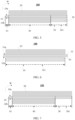
FIG. 1 is a schematic structural diagram of an electrode assembly according to some embodiments of this application; -
FIG. 2 is a schematic cross-sectional structural diagram of a positive electrode plate in the electrode assembly ofFIG. 1 in an unwinding state in its thickness direction; -
FIG. 3 is a schematic structural diagram of the positive electrode plate ofFIG. 2 from a perspective of its thickness direction; -
FIG. 4 is a schematic structural diagram of an electrode assembly according to some embodiments of this application; -
FIG. 5 is a schematic cross-sectional structural diagram of a positive electrode plate in the electrode assembly ofFIG. 4 in an unwinding state in its thickness direction; -
FIG. 6 is a schematic structural diagram of a positive electrode plate according to an embodiment of this application; and -
FIG. 7 is a schematic cross-sectional structural diagram of a positive electrode plate of Comparative example 1 in an unwinding state in its thickness direction. - To make the objectives, technical solutions, and advantages of this application more comprehensible, the following describes this application in detail with reference to accompanying drawings and embodiments. Apparently, the described embodiments are merely some but not all of the embodiments of this application. All other embodiments obtained by persons of ordinary skill in the art based on some embodiments of this application shall fall within the protection scope of this application.
- It should be noted that, in the specific embodiments of this application, an example in which a lithium-ion battery is used as an electrochemical apparatus is used to illustrate this application. However, the electrochemical apparatus of this application is not limited to the lithium-ion battery.
- Most electrode assemblies in electrochemical apparatuses (such as lithium-ion batteries) have an exposed positive electrode current collector. The positive electrode current collector in the prior art usually uses aluminum foil with a mass percentage of element silicon being 0.06% to 0.18%, where element silicon is mostly present in the form of silicon dioxide or silicate. With the continuous improvement of the voltage system of electrochemical apparatuses, the ability of the positive electrode plate at full charge to oxidize the electrolyte is also enhanced. To lower the oxidation of the electrolyte by the positive electrode plate, the protection effect on the positive electrode plate and negative electrode plate under high voltage is generally enhanced in the prior art by continuously increasing the percentage of the fluorine-containing compound in the electrolyte.
- However, fluorine-containing compounds such as fluorine-containing additives and fluorine-containing lithium salts are prone to defluorination reactions under the action of Lewis acids (such as PF5) generated by electrolyte decomposition, resulting in HF. In this case, after the electrochemical apparatus is injected with an electrolyte, the electrolyte comes into contact with the exposed aluminum foil, and the HF in the electrolyte may react with the components in the aluminum foil such as silicon dioxide or silicate, generating by-products fluorosilicon compounds. The by-products fluorosilicon compounds diffuse inside the electrochemical apparatus and accumulate in a specific zone of the positive electrode plate (for example, a position at the edge of a positive electrode active material layer disposed in a single-sided region of the positive electrode current collector), causing abnormalities in the positive electrode plate (for example, noticeable color difference and increased percentage of element silicon in local zones). Normal lithium deintercalation cannot take place in the abnormal zone of the positive electrode plate, and lithium ions are released from edges of the abnormal zone of the positive electrode plate, resulting in lithium precipitation due to insufficient sites for lithium intercalation in the negative electrode plate corresponding to the edges of the abnormal zone and ultimately leading to failure of the electrochemical apparatus during the charge-discharge cycles. To solve problem of failure of electrochemical apparatuses during charge-discharge cycles, this application provides an electrochemical apparatus and an electronic apparatus.
- A first aspect of this application provides an electrochemical apparatus, including an electrode assembly, an electrolyte, and a packaging bag for accommodating the electrode assembly and the electrolyte. The electrolyte includes a fluorine-containing compound, the electrode assembly includes a positive electrode plate, a negative electrode plate, and a separator, the separator is disposed between the positive electrode plate and the negative electrode plate, and the electrode assembly is provided with the positive electrode plate, the negative electrode plate, and the separator stacked together. The positive electrode plate includes a positive electrode current collector, a positive electrode active material layer, and an inactive material layer. The positive electrode current collector is an aluminum foil and includes element silicon, and a mass percentage of element silicon in the positive electrode current collector is a%, with 0.03 ≤ a ≤ 0.13. The positive electrode current collector includes a first surface and a second surface opposite each other. The positive electrode current collector includes element aluminum and element silicon, and a mass percentage of element silicon in the positive electrode current collector is a%, with 0.03 ≤ a ≤ 0.13. The positive electrode current collector has a single-sided region. The single-sided region is located at an end of the positive electrode current collector in its length direction, including a first portion, and a second surface of the first portion is located on an outer surface of the electrode assembly. A first surface of the single-sided region is provided with the positive electrode active material layer, and a second surface of the single-sided region is provided with the inactive material layer. The inactive material layer includes an inactive material, and the inactive material includes at least one of an inorganic oxide or an elemental nonmetal. The length direction of the positive electrode current collector is a winding direction of the wound electrode assembly.
- It can be understood that the single-sided region is a section of the positive electrode current collector. Therefore, the first surface of the single-sided region is the first surface of the positive electrode current collector, and the second surface of the single-sided region is the second surface of the positive electrode current collector. The first portion is a section or all of the single-sided region, meaning that it is also a section of the positive electrode current collector. Therefore, the first surface of the first portion is the first surface of the positive electrode current collector and the second surface of the first portion is the second surface of the positive electrode current collector.
- For example, a value of a is 0.03, 0.04, 0.05, 0.06, 0.07, 0.08, 0.09, 0.10, 0.11, 0.12, or 0.13, or any value between any two of the foregoing values. When the mass percentage of element silicon in the positive electrode current collector is too small, that is, when the value of a is less than 0.03, aluminum foil has insufficient strength and poor wear resistance, and the risk of breakage is likely to occur in cold pressing during the preparation of the positive electrode plate. When the mass percentage of element silicon in the positive electrode current collector is too large, that is, when the value of a is less than 0.13, the excessive strength of the positive electrode current collector leads to a decrease in its ductility, there is a risk of fracture of the positive electrode current collector during subsequent winding (for example, winding of the positive electrode current collector, winding of the positive electrode plate, and winding during the preparation of the electrode assembly); and the conductivity of the positive electrode current collector deteriorates. With the mass percentage of element silicon in the positive electrode current collector being controlled within the foregoing range, abnormalities in the preparation process of the positive electrode current collector can be reduced, the strength and toughness of the positive electrode current collector meet its preparation process requirements, and the positive electrode current collector has good conductivity.
- The single-sided region includes a first portion, and a second surface of the first portion is located on an outer surface of the electrode assembly. An inactive material layer is provided on the second surface of the single-sided region to act as an inert layer between the electrolyte and the positive electrode current collector, physically isolating the electrolyte to lower the possibility of generation of by-products by reactions between the electrolyte and the positive electrode current collector and reduce the percentage of the by-products. This lowers the risk of the by-products accumulating in a specific zone or another zone of the positive electrode plate.
- Generally speaking, with the use of the positive electrode current collector provided in this application, with an inactive material layer provided on a second surface of a single-sided region of the positive electrode current collector, and in conjunction with the electrolyte of this application, after the electrochemical apparatus has undergone charge-discharge cycles, the risks of abnormality in the positive electrode plate and lithium precipitation in the negative electrode plate are lowered, thereby reducing the risk of failure of the electrochemical apparatus during the charge-discharge cycles.
- The type of aluminum foil is not particularly limited in this application and may be any well-known aluminum foil in the art, provided that the objectives of this application can be achieved.
- The method of controlling the mass percentage of element silicon in the positive electrode current collector is not particularly limited in this application, provided that the objectives of this application can be achieved. For example, the controlling can be implemented by adjusting the ratio of individual components in the positive electrode current collector and the types of individual components.
- For example, in some embodiments of this application, as shown in
FIG. 1 to FIG. 5 , anelectrode assembly 001 has a wound structure, with the winding direction indicated by W. Theelectrode assembly 001 includes apositive electrode plate 100, anegative electrode plate 200, and aseparator 300 disposed between thepositive electrode plate 100 and thenegative electrode plate 200. Thepositive electrode plate 100 includes a positive electrodecurrent collector 10, a positive electrodeactive material layer 20, and aninactive material layer 50. The positive electrodecurrent collector 10 includes afirst surface 10a and asecond surface 10b opposite each other. The positive electrodecurrent collector 10 includes a single-sidedregion 30. Afirst surface 10a of the single-sidedregion 30 is provided with the positive electrodeactive material layer 20, and asecond surface 10b of the single-sidedregion 30 is provided with theinactive material layer 50. The single-sidedregion 30 includes afirst portion 301, and asecond surface 10b of thefirst portion 301 is located on an outer surface of theelectrode assembly 001. As shown inFIG. 1 to FIG. 3 , the positive electrodecurrent collector 10 further includes a double-sided region 40, a first double-sidednon-coated region 61, and a second double-sidednon-coated region 62. Portions of the single-sidedregion 30 other than thefirst portion 301 are not located on the outer surface of theelectrode assembly 001. Thesecond surface 10b of thefirst portion 301 is located on the outer surface of theelectrode assembly 001. The positive electrode current collector in the electrode assembly shown inFIG. 4 does not include the second double-sidednon-coated region 62, but includes a double-sided region 40, a single-sidedregion 30, and a first double-sidednon-coated region 61. As shown inFIG. 4 andFIG. 5 , thefirst portion 301 can be understood as the single-sidedregion 30, and thesecond surface 10b of thefirst portion 301 can also be understood as thesecond surface 10b of the single-sidedregion 30, meaning that thesecond surface 10b of the single-sidedregion 30 is located on the outer surface of theelectrode assembly 001. - For example, in some embodiments of this application, the electrode assembly has a stacked structure. The electrode assembly is composed of a positive electrode plate, a negative electrode plate, and a separator stacked together, and the separator is located between the positive electrode plate and the negative electrode plate. On both outermost sides of the electrode assembly in thickness direction, a single-sided positive electrode plate is provided. Specifically, as shown in
FIG. 6 , the single-sided positive electrode plate includes a positive electrodecurrent collector 10. The positive electrodecurrent collector 10 includes afirst surface 10a and asecond surface 10b opposite each other. The positive electrodecurrent collector 10 includes a single-sidedregion 30. Afirst surface 10a of the single-sidedregion 30 is provided with the positive electrodeactive material layer 20, and asecond surface 10b of the single-sidedregion 30 is provided with theinactive material layer 50. The single-sidedregion 30 includes afirst portion 301, and asecond surface 10b of thefirst portion 301 is located on an outer surface of theelectrode assembly 001. Thefirst portion 301 can be understood as the single-sidedregion 30, and thesecond surface 10b of thefirst portion 301 can also be understood as thesecond surface 10b of the single-sidedregion 30, meaning that thesecond surface 10b of the single-sidedregion 30 is located on the outer surface of the electrode assembly. Generally, the positive electrode plate not located on the outer surface of the electrode assembly is a double-sided positive electrode plate. The double-sided positive electrode plate includes a positive electrode current collector. The positive electrode current collector includes a first surface and a second surface opposite each other, and the first surface and the second surface are both provided with a positive electrode active material layer. - In some embodiments of this application, the inactive material layer covers the second surface of the single-sided region. It can be understood that the inactive material layer is provided on the entire zone of the second surface of the single-sided region. In this way, the inactive material layer acts as an inert layer between the electrolyte and the positive electrode current collector to completely isolate the electrolyte from the positive electrode current collector, further lowering the possibility of contact between the electrolyte and the positive electrode current collector and further reducing the percentage of the by-products generated by reactions between the electrolyte and the positive electrode current collector. As a result, the risk of the by-products accumulating in a specific zone or another zone of the positive electrode plate is reduced. The risks of abnormality in the positive electrode plate and lithium precipitation in the negative electrode plate after the electrochemical apparatus has undergone charge-discharge cycles are lowered, thereby lowering the risk of failure of the electrochemical apparatus during the charge-discharge cycles.
- In some embodiments of this application, the inorganic oxide includes at least one of aluminum trioxide, silicon oxide, calcium oxide, boehmite, or calcium carbonate, and the elemental nonmetal includes at least one of silicon, carbon, or boron. The use of the foregoing types of inorganic oxides and elemental nonmetals is more conducive to exerting the inertness of the inactive material layer, physically isolating the electrolyte from the positive electrode current collector to lower the possibility of generation of by-products by reactions between the electrolyte and the positive electrode current collector and reduce the percentage of the by-products. As a result, the risk of the by-products accumulating in a specific zone or another zone of the positive electrode plate is reduced. Therefore, the risks of abnormality in the positive electrode plate and lithium precipitation in the negative electrode plate after the electrochemical apparatus has undergone charge-discharge cycles are lowered, thereby lowering the risk of failure of the electrochemical apparatus during the charge-discharge cycles.
- The form of adding the elemental nonmetal in the inactive material layer is not particularly limited in this application, provided that the objectives of this application can be achieved. For example, silicon is added in the form of silicon powder, carbon is added in the form of conductive carbon, and boron is added in the form of elemental boron powder.
- In some embodiment of this application, Dv50 of the inorganic oxide particles is 0.1 µm to 30 µm, and Dv50 of the elemental nonmetal is 0.1 µm to 10 µm. For example, Dv50 of the inorganic oxide is 0.1 µm, 1 µm, 5 µm, 10 µm, 15 µm, 20 µm, 25 µm, or 30 µm, or any value between any two of the foregoing values; and Dv50 of the elemental nonmetal is 0.1 µm, 1 µm, 5 µm, or 10 µm, or any value between any two of the foregoing values. With the average particle sizes Dv50 of the inorganic oxide and elemental nonmetal being controlled within the foregoing ranges, it is more conducive to controlling the thickness of the inactive material layer to be within an appropriate range, allowing the inactive material layer to physically isolate the electrolyte from the positive electrode current collector, in order to lower the possibility of generation of by-products by reactions between the electrolyte and the positive electrode current collector and reduce the percentage of the by-products. As a result, the risk of the by-products accumulating in a specific zone or another zone of the positive electrode plate is reduced. Therefore, the risks of abnormality in the positive electrode plate and lithium precipitation in the negative electrode plate after the electrochemical apparatus has undergone charge-discharge cycles are lowered, thereby lowering the risk of failure of the electrochemical apparatus during the charge-discharge cycles.
- In this application, Dv50 represents a particle size of the inorganic oxide or elemental nonmetal at a cumulative volume of 50% in a volume-based particle size distribution as measured by starting from small particle sizes.
- In some embodiment of this application, the inactive material layer further includes an inactive material layer binder, and the inactive material layer binder includes at least one of polytetrafluoroethylene, chloroprene rubber, nitrile rubber, styrene-butadiene rubber, carboxylated rubber, chlorosulfonated polyethylene rubber, phenolic resin, epoxy resin, or silicone resin. A mass ratio of the inactive material to the inactive material layer binder is (70 to 98):(2 to 30). For example, a mass ratio of the inactive material to the binder is 70:30, 75:25, 80:20, 85:15, 90:10, 95:5, or 98:2, or any value between any two of the foregoing values. With the use of the foregoing the inactive material layer binder and the mass ratio of the inactive material layer to the the inactive material layer binder in the inactive material layer being controlled within the foregoing range, it is more conducive to preparing an inactive material layer with excellent isolation effect to isolate the electrolyte from the positive electrode current collector, further lowering the possibility of contact between the electrolyte and the positive electrode current collector and further reducing the percentage of the by-products generated by reactions between the electrolyte and the positive electrode current collector. As a result, the risk of the by-products accumulating in a specific zone or another zone of the positive electrode plate is reduced. The risks of abnormality in the positive electrode plate and lithium precipitation in the negative electrode plate after the electrochemical apparatus has undergone charge-discharge cycles are lowered, thereby lowering the risk of failure of the electrochemical apparatus during the charge-discharge cycles.
- In some embodiment of this application, the fluorine-containing compound includes a fluorine-containing additive, and a mass percentage of the fluorine-containing additive in the electrolyte is c%, with 0.1 ≤ c ≤ 40. For example, a value of c is 0.1, 2.0, 5.0, 10.0, 15.0, 20.0, 25.0, 30.0, 35.0, or 40.0, or any value between any two of the foregoing values. With the fluorine-containing additive included in the electrolyte and the mass percentage of the fluorine-containing additive in the electrolyte being controlled within the foregoing range, the protective ability of the electrolyte on the negative electrode plate can be enhanced, and a uniform and dense protective film can be formed on the surface of the negative electrode plate, thereby improving the cycling performance of the electrochemical apparatus while reducing the percentage of fluorinated silicon compounds generated by reactions between HF in the electrolyte and element silicon in the positive electrode current collector. In this way, the risk of abnormality in the positive electrode plate is lowered, thereby lowering the risk of failure of the electrochemical apparatus during the charge-discharge cycles.
- In some embodiments of this application, a thickness of the inactive material layer is b µm, with 3 ≤ b ≤ 20. For example, a value of b is 3, 4, 6, 8, 10, 12, 14, 16, 18, or 20, or any value between any two of the foregoing values. With the thickness of the inactive material layer being controlled within the foregoing range and without increasing the volume of the electrochemical apparatus and affecting the energy density of the electrochemical apparatus, it is more conducive for the inactive material layer to act as an inert layer between the electrolyte and the positive electrode current collector to isolate the electrolyte from the positive electrode current collector, lowering the possibility of contact between the electrolyte and the positive electrode current collector and reducing the percentage of the by-products generated by reactions between the electrolyte and the positive electrode current collector. As a result, the risk of the by-products accumulating in a specific zone or another zone of the positive electrode plate is reduced. The risks of abnormality in the positive electrode plate and lithium precipitation in the negative electrode plate after the electrochemical apparatus has undergone charge-discharge cycles are lowered, thereby lowering the risk of failure of the electrochemical apparatus during the charge-discharge cycles. In some embodiments of this application, 3 ≤ b ≤ 10. This can make the inactive material layer have a suitable thickness to meet the need to lower the risk of failure of the electrochemical apparatus during the charge-discharge cycles and can also lower the influence of the inactive material layer on the energy density of the electrochemical apparatus. In addition, this can make the roll pressing device act on the inactive material layer in the roll pressing process after the electrode plate has been coated, lowering the risk of breakage of the positive electrode plate caused by the roll pressing device directly transitioning to the positive electrode current collector from the positive electrode active material layer.
- The method of controlling the thickness of the inactive material layer is not particularly limited in this application, provided that the objectives of this application can be achieved. For example, this is implemented by controlling Dv50 of the inactive material or the coating weight of slurry on the inactive material layer.
- In some embodiments of this application, 0.003 ≤ a/b ≤ 0.025. In some embodiments of this application, 0.003 ≤ a/b ≤ 0.02. For example, the value of a/ b is 0.003, 0.005, 0.01, 0.015, 0.02, or 0.025, or any value between any two of the foregoing values. With the value of a/b being controlled within the foregoing range and the synergistic effect between the mass percentage of element silicon in the positive electrode current collector and the thickness of the inactive material layer, the thickness of the inactive material allows the inactive material to fully exert its isolation effect, isolating the electrolyte from the positive electrode current collector without increasing the volume of the electrochemical apparatus and affecting the energy density of the electrochemical apparatus, so that the possibility of generation of by-products by reactions between the electrolyte and the positive electrode current collector is lowered, the percentage of the by-products is reduced, and the risk of by-products accumulating in a specific area or another area of the positive electrode plate is lowered. Therefore, this is more conducive to lowering the risk of failure of the electrochemical apparatus during the charge-discharge cycles.
- In some embodiments of this application, 0.1 ≤ c/ b ≤ 13. In some embodiments of this application, 0.1 ≤ c/ b ≤ 6.7. For example, a value of c /b is 0.1, 1, 2, 3, 4, 5, 6, 7, 8, 9, 10, 11, 12, or 13, or any value between any two of the foregoing values. As an inert layer between the electrolyte and the positive electrode current collector, the inactive material layer can physically isolate the electrolyte. With the value of c/b being controlled within the foregoing range and the synergistic effect between the mass percentage of the fluorine-containing additive in the electrolyte and the thickness of the inactive material layer, the possibility of generation of by-products by reactions between the electrolyte and the positive electrode current collector can be further lowered to further reduce the percentage of the by-products, and the risk of by-products accumulating in a specific area or another area of the positive electrode plate is further lowered. Therefore, this is more conducive to lowering the risk of failure of the electrochemical apparatus during the charge-discharge cycles.
- In some embodiments of this application, the fluorine-containing additive includes at least one of fluoroethylene carbonate (FEC), difluoromethyl ethylene carbonate (DFEC), bis(difluoromethyl) ethylene carbonate, bis(trifluoromethyl) ethylene carbonate, bis(2-fluoroethyl) ethylene carbonate, bis(2,2-difluoroethyl) ethylene carbonate, bis(2,2,2-trifluoroethyl) ethylene carbonate, 2-fluoroethylmethylethylene carbonate, 2,2-difluoroethyl methyl ethylene carbonate, or 2,2,2-trifluoroethyl methyl ethylene carbonate. The use of the foregoing type of fluorine-containing additive is more conducive to weakening the ability of the positive electrode plate to oxidize the electrolyte and forming a uniform and dense protective film on surfaces of the positive electrode plate and negative electrode plate to protect the positive electrode plate and negative electrode plate.
- In some embodiments of this application, the fluorine-containing substance includes a fluorine-containing lithium salt, and the fluorine-containing lithium salt includes at least one of lithium hexafluorophosphate, lithium difluorophosphate (LiPF2), lithium bis(trifluoromethanesulfonyl)imide (LiTFSI), lithium bis(fluorosulfonyl)imide (LiTSI), lithium tetrafluoroborate (LiBF4), lithium difluoro(oxalato)borate (LiBF2(C2O4), LiDFOB), lithium hexafluoroantimonate (LiSbF6), lithium hexafluoroarsenate (LiAsF6), lithium perfluorobutanesulfonate (LiC4F9SO3), lithium bis(sulfonyl)imide (LiN(CxF2x+1SO2)(CyF2y+1SO2), where x and y are positive integers and x ≤ 10, y ≤ 10) or lithium fluoride (LiF). The addition of the fluorine-containing lithium salt is more conducive to providing high ionic conductivity for faster lithium ion transport. Preferably, the fluorine-containing lithium salt includes at least one of LiPF6, LiTFSI, or LiTSI, and this is more conducive to lowering the production cost of the electrochemical apparatus. The mass percentage of the fluorine-containing lithium salt in the electrolyte is not particularly limited in this application, provided that the objectives this application can be achieved. For example, the mass percentage of the fluorine-containing lithium salt in the electrolyte is 8% to 20%.
- In some embodiments of this application, the electrode assembly has a stacked structure.
- In some embodiments of this application, as shown in
FIG. 1 and FIG. 2 , the electrode assembly has a wound structure, the positive electrodecurrent collector 10 further includes a double-sided region 40, and the double-sided region 40 is sequentially connected to the single-sidedregion 30 in a winding direction W. A positive electrodeactive material layer 20 is provided on both thefirst surface 10a and thesecond surface 10b of the double-sided region 40. - The thickness of the positive electrode current collector is not particularly limited in this application, provided that the objectives of this application can be achieved. For example, the thickness of the positive electrode current collector is 8 µm to 20 µm.
- The preparation method of positive electrode current collector is not particularly limited in this application, and any well-known preparation method in the art can be used, provided that the objectives of this application can be achieved.
- The compressed density of the cold pressed positive electrode plate and negative electrode plate is not particularly limited in this application, provided that the objectives of this application can be achieved. For example, the compacted density of the positive electrode plate and negative electrode plate after cold pressing is 3.9 g/cm3 to 4.3 g/cm3.
- The positive electrode active material layer of this application includes a positive electrode active material. The type of the positive electrode active material is not particularly limited in this application, provided that the objectives of this application can be achieved. For example, the positive electrode active material may include at least one of lithium nickel cobalt manganate (such as common NCM811, NCM622, NCM523, NCM111), lithium nickel cobalt aluminate, lithium iron phosphate, lithium-rich manganese-based material, lithium cobaltate (LiCoO2), lithium manganate, lithium iron manganese phosphate, lithium titanate, or the like. In this application, the positive electrode active material may further include a non-metal element, for example, fluorine, phosphorus, boron, chlorine, silicon, and sulfur. These elements can further improve the stability of the positive electrode active material. Optionally, the positive electrode active material layer further includes a conductive agent and a binder. The types of the conductive agent and binder in the positive electrode active material layer is not particularly limited in this application, provided that the objectives of this application can be achieved. The mass ratio of the positive electrode active material, conductive agent, and binder in the positive electrode active material layer is not particularly limited in this application, and persons skilled in the art can make selection based on actual needs, provided that the objectives of this application can be achieved. For example, the mass ratio of the positive electrode active material, conductive agent, and binder in the positive electrode active material layer is (97.5 to 97.9):(0.9 to 1.7):(1.0 to 2.0).
- The thickness of the positive electrode active material layer is not particularly limited in this application, provided that the objectives of this application can be achieved. For example, the thickness of the positive electrode active material layer is 30 µm to 120 µm.
- The negative electrode plate of this application includes a negative electrode current collector and a negative electrode active material layer disposed on at least one surface of the negative electrode current collector. The "negative electrode active material layer disposed on at least one surface of the negative electrode current collector" means that the negative electrode active material layer may be disposed on one surface of the negative electrode current collector in its thickness direction, or on two surfaces of the negative electrode current collector in its thickness direction. It should be noted that the "surface" herein may be an entire region or a partial region of the negative electrode current collector. This is not particularly limited in this application, provided that the objectives of this application can be achieved. The negative electrode current collector is not particularly limited in this application, provided that the objectives of this application can be achieved. For example, the negative electrode current collector may include copper foil, copper alloy foil, nickel foil, titanium foil, nickel foam, copper foam, or the like. The negative electrode active material layer includes a negative electrode active material. The type of the negative electrode active material is not particularly limited in this application, provided that the objectives of this application can be achieved. For example, the negative electrode active material may include at least one of natural graphite, artificial graphite, soft carbon, hard carbon, mesocarbon microbeads, tin-based materials, silicon-based materials, lithium titanate, transition metal nitrides, or natural flake graphite. Optionally, the negative electrode active material layer further includes at least one of a conductive agent, a stabilizer, or a binder. The types of the conductive agent, stabilizer, and binder in the negative electrode active material layer is not particularly limited in this application, provided that the objectives of this application can be achieved. The mass ratio of the negative electrode active material, conductive agent, stabilizer, and binder in the negative electrode active material layer is not particularly limited in this application, provided that the objectives of this application can be achieved. For example, the mass ratio of the negative electrode active material, conductive agent, stabilizer, and binder in the negative electrode active material layer is (97 to 98):(0.5 to 1.5):(0.5 to 1.5):(1.0 to 1.9).
- Thicknesses of the negative electrode current collector and the negative electrode active material layer are not particularly limited in this application, provided that the objectives of this application can be achieved. For example, the thickness of the negative electrode current collector is 5 µm to 20 µm, and the thickness of the negative electrode active material layer is 30 µm to 120 µm.
- The electrolyte of this application further includes a non-aqueous solvent. The non-aqueous solvent is not particularly limited in this application, provided that the objective of this application can be achieved. For example, the non-aqueous solvent may include but is not limited to at least one of dimethyl carbonate (DMC), diethyl carbonate (DEC), dipropyl carbonate (DPC), methyl propyl carbonate (MPC), ethyl propyl carbonate (EPC), methyl ethyl carbonate (MEC), ethylene carbonate (EC), propylene carbonate (PC), butylene carbonate (BC), ethyl acetate, n-propyl acetate, tert-butyl acetate, methyl propionate, ethyl propionate, or propyl propionate.
- The mass percentage of the non-aqueous solvent in the electrolyte is not particularly limited in this application, provided that the objectives of this application can be achieved. For example, the mass percentage of the non-aqueous solvent in the electrolyte is 70% to 99%.
- The separator and packaging bag are not particularly limited in this application and may be any well-known separator and packaging bag in the art, provided that the objectives of this application can be achieved.
- The electrochemical apparatus in this application is not particularly limited and may include any apparatus in which electrochemical reactions take place. In some embodiments, the electrochemical apparatus may include but is not limited to a lithium metal secondary battery, a lithium-ion secondary battery, a sodium-ion secondary battery, a lithium polymer secondary battery, or a lithium-ion polymer secondary battery.
- The preparation method of electrochemical apparatus is not particularly limited in this application and may be any well-known preparation method in the art, provided that the objectives of this application can be achieved.
- A second aspect of this application provides an electronic apparatus, including the electrochemical apparatus according to the first aspect of this application. Therefore, the electronic apparatus can provide the beneficial effects of the electrochemical apparatus according to the first aspect of this application.
- The electronic apparatus of this application is not particularly limited and may be any known electronic apparatus used in the prior art. In some embodiments, the electronic apparatus may include but is not limited to a notebook computer, a pen-input computer, a mobile computer, an electronic book player, a portable telephone, a portable fax machine, a portable copier, a portable printer, a stereo headset, a video recorder, a liquid crystal television, a portable cleaner, a portable CD player, a mini-disc, a transceiver, an electronic notepad, a calculator, a storage card, a portable recorder, a radio, a standby power source, a motor, an automobile, a motorcycle, a power-assisted bicycle, a bicycle, a lighting appliance, a toy, a game console, a clock, an electric tool, a flash lamp, a camera, a large household battery, and a lithium-ion capacitor.
- In the following, examples and comparative examples are given to describe some embodiments of this application in more detail. Various tests and evaluations are performed in the following methods.
- Lithium-ion batteries of each example and comparative example were taken, fully discharged, and then disassembled. For each battery, the positive electrode active material layer on the surface of the positive electrode current collector was washed away with N-methylpyrrolidone, and finally the positive electrode current collector was cleaned with DMC; and the cleaned positive electrode current collector was tested using an inductively coupled plasma spectrometer (ICP) to obtain percentages of element aluminum and element silicon.
- Lithium-ion batteries of each example and comparative example were taken and centrifuged to obtain 10 mL of electrolyte. With a gas chromatography detection method, the mass percentage of the fluorine-containing additive in the electrolyte can be obtained.
- Dv50 was measured with reference to the national standard GB/T 19077-2016 (Particle Size Distribution - Laser Diffraction Method) and using a laser particle size analyzer (such as Malvern Master Size 3000).
- Lithium-ion batteries of each example and comparative example were fully discharged and then disassembled. For each battery, the positive electrode plate was visually observed for abnormal appearance of a heterochromatic mark (also referred to as abnormal zone), that is, a significant color difference between a local zone and its surrounding zones. X-ray energy dispersive spectroscopy (EDS) testing was carried out on the positive electrode plate with the abnormal zone. If the percentage of element silicon in the abnormal zone was greater than 2wt%, the positive electrode plate was determined to have an abnormality. If the positive electrode plate did not exhibit abnormal appearance of a heterochromatic mark, indicating that there is no abnormal appearance on the positive electrode plate and no EDS testing was carried out on the positive electrode plate.
- The existence of abnormal appearance in the positive electrode plate and the percentage of element silicon greater than 2wt% in the abnormal zone were used to characterize the problem of failure of the electrochemical apparatus during charge-discharge cycles.
- In the <preparation of positive electrode plate> of each example or comparative example, during the cold pressing of the positive electrode plate, it was determined whether there is a fracture of the positive electrode current collector, breakage of the positive electrode plate, falling-off of the positive electrode active material layer, or significant fluctuation in the laser positioning of the positive electrode plate.
- Inactive material inorganic oxide aluminum trioxide and inactive material layer binder polytetrafluoroethylene (average molecular weight 500,000) were mixed at a mass ratio of 70:30 to obtain an inactive material layer slurry. Dv50 of the inorganic oxide is 0.1 µm.
- Positive electrode active material LiCoO2, conductive agent conductive carbon black, and binder polyvinylidene difluoride (PVDF) were mixed at a mass ratio of 96:2:2, added with N-methylpyrrolidone (NMP), and stirred to uniformity under the action of a vacuum mixer to obtain a positive electrode slurry, where the solid content of the positive electrode slurry was 70wt%.
- The positive electrode slurry was evenly applied to the
first surfaces 10a of the double-sided region 40 and the single-sidedregion 30 of the positive electrodecurrent collector 10 shown inFIG. 5 , and then dried at 120°C for 1 hour. The foregoing steps was repeated on thesecond surface 10b of the double-sided region 40 of the positive electrodecurrent collector 10, and an inactive material layer slurry was applied to thesecond surface 10b of the single-sidedregion 30 of the positive electrodecurrent collector 10, so that theinactive material layer 50 covered thesecond surface 10b of the single-sidedregion 30, thereby obtaining the positive electrode plate as shown inFIG. 5 . The positive electrode current collector was dried at 120°C for 1 hour, followed by cold pressing, cutting, and slitting to obtain positive electrode plates with dimensions of 78 mm × 875 mm. The dimensions of thefirst surface 10a of the double-sided region 40 were 78 mm × 780 mm, the dimensions of thefirst surface 10a of the single-sidedregion 30 were 78 mm × 80 mm, the same as the dimensions of thefirst surface 10a of the first portion 31, and the dimensions of the firstnon-coated region 61 were 78 mm × 15 mm. The thickness of the positive electrodeactive material layer 20 was 100 µm, the thickness b of theinactive material layer 50 was 3 µm, and the thickness of the positive electrodecurrent collector 10 was 10 µm. The mass percentage of element silicon in the positive electrodecurrent collector 10 was a% = 0.03%. - Negative electrode active material artificial graphite, binder styrene-butadiene rubber, and thickener sodium carboxymethylcellulose were mixed at a mass ratio of 97.4:1.4:1.2, added with deionized water, and stirred to uniformity under the action of a vacuum mixer to obtain a negative electrode slurry, where the solid content of the negative electrode slurry was 75wt%. The negative electrode slurry was evenly applied to one surface of the negative electrode current collector copper foil having a thickness of 12 µm and dried at 120°C for 1 hour to obtain a negative electrode having a negative electrode active material layer coated on a single surface, with a coating thickness of 130 µm. The foregoing steps were repeated on another surface of the negative electrode current collector to obtain a negative electrode plate with the negative electrode active material layer coated on two surfaces. The negative electrode current collector was dried at 120°C for 1 hour, followed by cold pressing, cutting, and slitting to obtain negative electrode plates with dimensions of 74 mm × 867 mm.
- In an argon glove box with water content less than 10 ppm, EC, PC, and DEC were mixed at a mass ratio of 1:1:1 to obtain an organic solvent, then fluorine-containing lithium salt LiPF6 was added to the organic solvent to obtain a base electrolyte. Fluorine-containing additive FEC was added to the base electrolyte to obtain an electrolyte. The mass percentage of the fluorine-containing lithium salt LiPF6 in the electrolyte was 13.8%, and the mass percentage of the fluorine-containing additive FEC in the electrolyte was c%=38%.
- A porous polyethylene film with a thickness of 7 µm was used.
- The prepared positive electrode plate, separator, and negative electrode plate were stacked in sequence, with the separator positioned between the positive electrode plate and the negative electrode plate for separation, and wound to obtain an electrode assembly with a wound structure shown in
FIG. 4 . The electrode assembly was placed into an aluminum-plastic film packaging bag and dried, and then the electrolyte was injected, followed by processes such as vacuum sealing, standing, formation, degassing, and trimming, to obtain a lithium-ion battery. - These examples were the same as Example 1-1 except that the related preparation parameters were adjusted according to Table 1.
- These examples were the same as Example 1-1 except that the related preparation parameters were adjusted according to Table 2.
- This comparative example was the same as Example 1 except that in the <Preparation of positive electrode plate>, as shown in the positive electrode
current collector 10 inFIG. 7 , no inactive material layer was provided on the first portion of the positive electrode current collector, that is the second surface of the single-sided region, so that the prepared positive electrode plate was as shown inFIG. 7 . - These comparative examples were the same as Example 1-1 except that the related preparation parameters were adjusted according to Table 1.
- This comparative example was the same as Comparative example 1 except that the related preparation parameters were adjusted according to Table 1.
- The related preparation parameters and performance tests of each example and comparative example are shown in Tables 1 and 2.
Table 1 a (%) Inactive material Dv50 of inorganic oxide (µm) Dv50 of elemental nonmetal (µm) Inactive material layer binder N Abnormal appearance in positive electrode plate? Percentage of Si in abnormal zone of positive electrode plate (wt%) Abnormalities in preparation process of positive electrode plate? Example 1-1 0.03 Aluminum trioxide 0.1 \ Polytetrafluoroethylene 70:30 No - Significant fluctuation in laser positioning Example 1-2 0.06 Aluminum trioxide 0.1 \ Polytetrafluoroethylene 70:30 No - Significant fluctuation in laser positioning Example 1-3 0.13 Aluminum trioxide 0.1 \ Polytetrafluoroethylene 70:30 No - Significant fluctuation in laser positioning Example 1-4 0.06 Aluminum trioxide + carbon black (mass ratio of 50:1) 0.1 0.1 Polytetrafluoroethylene 70:30 No - N/A Example 1-5 0.06 Aluminum trioxide 10 \ Polytetrafluoroethylene 70:30 No - Significant fluctuation in laser positioning Example 1-6 0.06 Aluminum trioxide 30 \ Polytetrafluoroethylene 70:30 No - Significant fluctuation in laser positioning Example 1-7 0.06 Aluminum trioxide + conductive carbon (mass ratio of 50:1) 10 10 Polytetrafluoroethylene 70:30 No - N/A Example 1-8 0.06 Aluminum trioxide + conductive carbon (mass ratio of 50:1) 10 10 Polytetrafluoroethylene 85:15 No - N/A Example 1-9 0.06 Aluminum trioxide + conductive carbon (mass ratio of 50:1) 10 10 Polytetrafluoroethylene 98:2 No - N/A Comparative Example 1 0.06 \ \ \ \ \ Yes 2.3 N/A Comparative Example 2 0.01 Aluminum trioxide 10 \ Polytetrafluoroethylene 70:30 No - Significant fluctuation in laser positioning and fracture in cold pressing Comparative example 3 0.15 Aluminum trioxide 10 \ Polytetrafluoroethylene 70:30 Yes 2.2 Significant fluctuation in laser positioning Comparative example 4 0.01 \ \ \ \ \ No - Fracture in cold pressing Note: "N" in Table 1 represents the mass ratio of the inactive material to the inactive material layer binder; "\" in Table 1 indicates no corresponding parameter; and "-" in Table 1 indicates that there is no abnormality in the positive electrode plate, and there is no need to test the percentage of Si. - From Examples 1-1 to 1-9 and Comparative examples 1 to 4, it can be seen that with the use of the lithium-ion battery for which the positive electrode current collector has the mass percentage a% of element silicon in the positive electrode current collector within the range in this application and an inactive material layer is disposed on the second surface of the single-sided region of the positive electrode current collector, and in conjunction with the electrolyte of this application, after the lithium-ion battery has undergone charge-discharge cycles, there is no abnormal appearance on the positive electrode plate, indicating that the risk of failure of the lithium-ion battery during charge-discharge cycles is lowered, and there are no abnormalities in the preparation process of the positive electrode plate or only the problem of significant fluctuations in laser positioning, without affecting the use performance of the positive electrode plate. In Comparative examples 1 to 4, with the use of the lithium-ion battery without an inactive material layer provided on the second surface of the single-sided region of the positive electrode current collector and/or the mass percentage a% of element silicon in the positive electrode current collector not within the range in this application, an abnormal appearance is present on the positive electrode plate, the percentage of Si in the abnormal zone of the positive electrode plate is greater than 2wt%, and there are significant fluctuations in laser positioning and/or fracture in cold pressing, indicating that the risk of failure of the lithium-ion battery during the charge-discharge cycles has not been lowered.
- The mass percentage a% of element silicon in the positive electrode current collector usually affects the probability of failure of the lithium-ion battery during the charge-discharge cycles. From Examples 1-1 to 1-3 and Comparative examples 2 and 3, it can be seen that with the use of the lithium-ion battery with a mass percentage a% of element silicon in the positive electrode current collector within the range in this application, there is no abnormal appearance on the positive electrode plate, indicating that the risk of failure of the lithium-ion battery during the charge-discharge cycles is lowered, and there is only the problem of significant fluctuations in laser positioning, without affecting the use performance of the positive electrode plate.
- The type of the inactive material usually affects the probability of failure of the lithium-ion battery during the charge-discharge cycles. From Examples 1-2, 1-4, 1-5, and 1-7, it can be seen that with the use of the lithium-ion battery for which the type of inactive material is within the range in this application, there is no abnormal appearance on the positive electrode plate, indicating that the risk of failure of the lithium-ion battery during the charge-discharge cycles is lowered, and there are no abnormalities in the preparation process of the positive electrode plate or there is only the problem of significant fluctuations in laser positioning, without affecting the use performance of the positive electrode plate. In Examples 1-5 and 1-7, when an elemental nonmetal is used as the inactive material, especially carbon (added in the form of conductive carbon), no significant fluctuations in laser positioning occur in the preparation process of the positive electrode plate. In other words, in the continuous production process of the positive electrode plate, after the inactive material layer is applied to the surface of the positive electrode current collector, the laser accurately positions at the edge of the inactive material layer for coating and forming the positive electrode active material layer, thereby reducing fluctuations in a coating start position of the positive electrode active material layer. In this way, the process in the continuous production of the positive electrode plate can be simplified, lowering the cost of manual adjustment in the laser positioning of the positive electrode active material layer.
- Dv50 of the inorganic oxide and Dv50 of the elemental nonmetal usually affect the probability of failure of the lithium-ion battery during the charge-discharge cycles. From Examples 1-2 and 1-5 to 1-7, it can be seen that with the use of the lithium-ion battery for which Dv50 of the inorganic oxide and Dv50 of the elemental nonmetal are within the ranges in this application, there is no abnormal appearance on the positive electrode plate, indicating that the risk of failure of the lithium-ion battery during the charge-discharge cycles is lowered, and there are no abnormalities in the preparation process of the positive electrode plate or there is only the problem of significant fluctuations in laser positioning, without affecting the use performance of the positive electrode plate.
- The mass ratio of the inactive material to the inactive material layer binder usually affects the probability of failure of the lithium-ion battery during the charge-discharge cycles. From Examples 1-2, 1-8, and 1-9, it can be seen that with the use of the lithium-ion battery for which the mass ratio of the inactive material to the inactive material layer binder is within the range in this application, there is no abnormal appearance on the positive electrode plate, indicating that the risk of failure of the lithium-ion battery during the charge-discharge cycles is lowered, and there are no abnormalities in the preparation process of the positive electrode plate, without affecting the use performance of the positive electrode plate.
Table 2 a (%) b (µm) a/b Fluorine-containing additive c (%) c/b Abnormal appearance in positive electrode plate? Percentage of Si in abnormal zone of positive electrode plate (wt%) Abnormalities in preparation process of positive electrode plate? Example 1-2 0.06 3 0.02 FEC 38 12.7 No - N/A Example 2-1 0.06 10 0.006 FEC 38 3.8 No - N/A Example 2-2 0.06 20 0.003 FEC 38 1.9 No - N/A Example 2-3 0.075 3 0.025 FEC 38 12.7 Yes 1.5 N/A Example 2-4 0.06 3 0.02 FEC 0.3 0.1 No - N/A Example 2-5 0.06 3 0.02 FEC 20 6.7 No - N/A Example 2-6 0.06 3 0.02 DFEC 38 12.7 No - N/A Note: "-" in Table 2 indicates that there is no abnormality in the positive electrode plate, and there is no need to test the Si content. - The thickness b of the inactive material layer usually affects the probability of failure of the lithium-ion battery during the charge-discharge cycles. From Examples 1-2, 2-1, and 2-2, it can be seen that with the use of the lithium-ion battery for which the thickness b of the inactive material layer is within the range in this application, there is no abnormal appearance on the positive electrode plate or there is an abnormal appearance on the positive electrode plate but the percentage of Si in the abnormal zone is less than 2wt%, indicating that the risk of failure of the lithium-ion battery during the charge-discharge cycles is lowered, and there are no abnormalities in the preparation process of the positive electrode plate.
- The value of a/b usually affects the probability of failure of the lithium-ion battery during the charge-discharge cycles. From Examples 1-2 and 2-1 to 2-3, it can be seen that with the use of the lithium-ion battery for which the value of a/b is within the range in this application, there is no abnormal appearance on the positive electrode plate or there is an abnormal appearance on the positive electrode plate but the percentage of Si in the abnormal zone is less than 2wt%, indicating that the risk of failure of the lithium-ion battery during the charge-discharge cycles is lowered, and there are no abnormalities in the preparation process of the positive electrode plate.
- The mass percentage c% of the fluorine-containing additive in the electrolyte usually affects the probability of failure of the lithium-ion battery during the charge-discharge cycles. From Examples 1-2, 2-4, and 2-5, it can be seen that with the use of the lithium-ion battery for which the mass percentage c% of the fluorine-containing additive in the electrolyte is within the range in this application, there is no abnormal appearance on the positive electrode plate or there is an abnormal appearance on the positive electrode plate but the percentage of Si in the abnormal zone is less than 2wt%, indicating that the risk of failure of the lithium-ion battery during the charge-discharge cycles is lowered, and there are no abnormalities in the preparation process of the positive electrode plate.
- The type of fluorine-containing additive usually affects the probability of failure of the lithium-ion battery during the charge-discharge cycles. From Examples 1-2 and 2-6, it can be seen that with the use of the lithium-ion battery for which the type of fluorine-containing additive is within the range of this application, there is no abnormal appearance on the positive electrode plate or there is an abnormal appearance on the positive electrode plate but the percentage of Si in the abnormal zone is less than 2wt%, indicating that the risk of failure of the lithium-ion battery during the charge-discharge cycles is lowered, and there are no abnormalities in the preparation process of the positive electrode plate.
- The foregoing descriptions are merely preferred examples of this application, and are not intended to limit this application. Any modifications, equivalent replacements, improvements, and the like made without departing from the spirit and principle of this application shall fall within the protection scope of this application.
Claims (16)
- An electrochemical apparatus, comprising an electrode assembly, an electrolyte, and a packaging bag for accommodating the electrode assembly and the electrolyte, wherein the electrolyte comprises a fluorine-containing compound, the electrode assembly comprises a positive electrode plate, a negative electrode plate, and a separator, and the separator is disposed between the positive electrode plate and the negative electrode plate; whereinthe positive electrode plate comprises a positive electrode current collector, a positive electrode active material layer, and an inactive material layer, the positive electrode current collector is an aluminum foil and comprises element silicon, and a mass percentage of element silicon in the positive electrode current collector is a%, with 0.03 ≤ a ≤ 0.13; and whereinthe positive electrode current collector comprises a first surface and a second surface opposite each other; the positive electrode current collector has a single-sided region, the single-sided region comprises a first portion, a second surface of the first portion is located on an outer surface of the electrode assembly, a first surface of the single-sided region is provided with the positive electrode active material layer, and a second surface of the single-sided region is provided with the inactive material layer; the inactive material layer comprises an inactive material, and the inactive material comprises at least one of an inorganic oxide or an elemental nonmetal.
- The electrochemical apparatus according to claim 1, wherein the inactive material layer covers the second surface of the single-sided region.
- The electrochemical apparatus according to claim 1, wherein the inorganic oxide comprises at least one of aluminum trioxide, silicon oxide, calcium oxide, boehmite, or calcium carbonate; and/or
the elemental nonmetal comprises at least one of silicon, carbon, or boron. - The electrochemical apparatus according to claim 1, wherein Dv50 of the inorganic oxide is 0.1 µm to 30 µm, and/or Dv50 of the elemental nonmetal is 0.1 µm to 10 µm.
- The electrochemical apparatus according to claim 1, wherein the inactive material layer further comprises an inactive material layer binder, and the inactive material layer binder comprises at least one of polytetrafluoroethylene, chloroprene rubber, nitrile rubber, styrene-butadiene rubber, carboxylated rubber, chlorosulfonated polyethylene rubber, phenolic resin, epoxy resin, or silicone resin; and
a mass ratio of the inactive material to the inactive material layer binder is (70 to 98):(2 to 30). - The electrochemical apparatus according to claim 1, wherein the fluorine-containing compound comprises a fluorine-containing additive, and a mass percentage of the fluorine-containing additive in the electrolyte is c%, with 0.1 ≤ c ≤ 40.0.
- The electrochemical apparatus according to claim 6, wherein a thickness of the inactive material layer is b µm, with 3 ≤ b ≤ 20.
- The electrochemical apparatus according to claim 7, wherein 3 ≤ b ≤ 10.
- The electrochemical apparatus according to claim 7, wherein 0.003 ≤ a/b ≤ 0.025.
- The electrochemical apparatus according to claim 7, wherein 0.003 ≤ a/b ≤ 0.02.
- The electrochemical apparatus according to claim 7, wherein 0.1 ≤ c/b ≤ 13.
- The electrochemical apparatus according to claim 7, wherein 0.1 ≤ c/b ≤ 6.7.
- The electrochemical apparatus according to claim 6, wherein the fluorine-containing additive comprises at least one of fluoroethylene carbonate, difluoromethyl ethylene carbonate, bis(difluoromethyl) ethylene carbonate, bis(trifluoromethyl) ethylene carbonate, bis(2-fluoroethyl) ethylene carbonate, bis(2,2-difluoroethyl) ethylene carbonate, bis(2,2,2-trifluoroethyl) ethylene carbonate, 2-fluoroethylmethylethylene carbonate, 2,2-difluoroethyl methyl ethylene carbonate, or 2,2,2-trifluoroethyl methyl ethylene carbonate.
- The electrochemical apparatus according to claim 1, wherein the fluorine-containing compound comprises a fluorine-containing lithium salt, and the fluorine-containing lithium salt comprises at least one of lithium hexafluorophosphate, lithium difluorophosphate, lithium bis(trifluoromethanesulfonyl)imide, lithium bis(fluorosulfonyl)imide, lithium tetrafluoroborate, lithium difluoro(oxalato)borate, lithium hexafluoroantimonate, lithium hexafluoroarsenate, lithium perfluorobutanesulfonate, lithium bis(sulfonyl)imide, or lithium fluoride.
- The electrochemical apparatus according to claim 1, wherein the electrode assembly has a stacked structure; or,
the electrode assembly has a wound structure, the positive electrode current collector further comprises a double-sided region, and the double-sided region is sequentially connected to the single-sided region in a winding direction. - An electronic apparatus, comprising the electrochemical apparatus according to any one of claims 1 to 15.
Applications Claiming Priority (1)
| Application Number | Priority Date | Filing Date | Title |
|---|---|---|---|
| PCT/CN2022/122550 WO2024065386A1 (en) | 2022-09-29 | 2022-09-29 | Electrochemical device and electronic device |
Publications (2)
| Publication Number | Publication Date |
|---|---|
| EP4579768A1 true EP4579768A1 (en) | 2025-07-02 |
| EP4579768A4 EP4579768A4 (en) | 2025-10-08 |
Family
ID=86781989
Family Applications (1)
| Application Number | Title | Priority Date | Filing Date |
|---|---|---|---|
| EP22960024.2A Pending EP4579768A4 (en) | 2022-09-29 | 2022-09-29 | ELECTROCHEMICAL DEVICE AND ELECTRONIC DEVICE |
Country Status (4)
| Country | Link |
|---|---|
| US (1) | US20250226414A1 (en) |
| EP (1) | EP4579768A4 (en) |
| CN (1) | CN116325266A (en) |
| WO (1) | WO2024065386A1 (en) |
Families Citing this family (3)
| Publication number | Priority date | Publication date | Assignee | Title |
|---|---|---|---|---|
| CN116632160A (en) * | 2023-06-26 | 2023-08-22 | 宁德新能源科技有限公司 | A secondary battery and electronic device |
| CN117691206A (en) * | 2023-12-27 | 2024-03-12 | 厦门新能达科技有限公司 | Electrochemical device, battery pack and electric equipment |
| CN118398765B (en) * | 2024-05-17 | 2025-11-25 | 浙江吉利控股集团有限公司 | Electrode assembly, method for manufacturing electrode assembly, and electrochemical device |
Family Cites Families (11)
| Publication number | Priority date | Publication date | Assignee | Title |
|---|---|---|---|---|
| JP2008093933A (en) * | 2006-10-11 | 2008-04-24 | Matsushita Electric Ind Co Ltd | Vacuum insulation |
| CN101752549B (en) * | 2008-12-02 | 2013-02-27 | Tcl集团股份有限公司 | Lithium polymer battery and method for producing positive pole plate for same |
| KR101202998B1 (en) * | 2010-03-26 | 2012-11-20 | 토요 알루미늄 치바 가부시키가이샤 | Pure aluminum hard foil for battery collector |
| JP2012224927A (en) * | 2011-04-21 | 2012-11-15 | Mitsubishi Alum Co Ltd | Aluminum alloy foil for positive electrode current collector of lithium ion battery, and method for manufacturing the same |
| CN105355956B (en) * | 2015-10-16 | 2018-01-19 | 广东烛光新能源科技有限公司 | Electrochemical cell and preparation method thereof |
| US20180145317A1 (en) * | 2016-11-18 | 2018-05-24 | Semiconductor Energy Laboratory Co., Ltd. | Positive electrode active material, method for manufacturing positive electrode active material, and secondary battery |
| KR102391534B1 (en) * | 2018-05-15 | 2022-04-28 | 주식회사 엘지에너지솔루션 | Negative electrode, and lithium secondarty battery comprising the negative electrode |
| CN109244475B (en) * | 2018-11-05 | 2024-06-21 | 宁德新能源科技有限公司 | Electrochemical device and electronic device including the same |
| CN111261834A (en) * | 2020-03-25 | 2020-06-09 | 宁德新能源科技有限公司 | Negative pole piece, electrochemical device and electronic device |
| CN114122404A (en) * | 2021-11-29 | 2022-03-01 | 珠海冠宇电池股份有限公司 | Pole piece and electrochemical device |
| CN114725388B (en) * | 2022-03-16 | 2025-04-18 | 宁德新能源科技有限公司 | Electrochemical devices and electronic devices |
-
2022
- 2022-09-29 EP EP22960024.2A patent/EP4579768A4/en active Pending
- 2022-09-29 CN CN202280007015.3A patent/CN116325266A/en active Pending
- 2022-09-29 WO PCT/CN2022/122550 patent/WO2024065386A1/en not_active Ceased
-
2025
- 2025-03-26 US US19/090,648 patent/US20250226414A1/en active Pending
Also Published As
| Publication number | Publication date |
|---|---|
| US20250226414A1 (en) | 2025-07-10 |
| CN116325266A (en) | 2023-06-23 |
| WO2024065386A1 (en) | 2024-04-04 |
| EP4579768A4 (en) | 2025-10-08 |
Similar Documents
| Publication | Publication Date | Title |
|---|---|---|
| EP4207351A1 (en) | Electrochemical apparatus and electronic apparatus | |
| EP4138167A2 (en) | Electrochemical device and electronic device | |
| JP4780833B2 (en) | Non-aqueous electrolyte and non-aqueous electrolyte secondary battery | |
| EP4579768A1 (en) | Electrochemical device and electronic device | |
| KR20250044928A (en) | Lithium batteries and electrical devices | |
| EP4489109A1 (en) | Electrochemical device, and electronic device comprising same | |
| JP6627904B2 (en) | Non-aqueous electrolyte for secondary battery and non-aqueous electrolyte secondary battery using the same | |
| EP4246609A1 (en) | Negative electrode plate and preparation method therefor, secondary battery, battery module, battery pack and power-consuming apparatus | |
| EP4693589A1 (en) | Secondary battery and electrical apparatus | |
| US20240006597A1 (en) | Electrochemical device and electronic device using same | |
| US20250192238A1 (en) | Electrochemical apparatus and electronic apparatus | |
| US20250158128A1 (en) | Electrochemical device and electronic device including same | |
| EP4576246A2 (en) | Secondary battery and electric device including such secondary battery | |
| JP7428346B2 (en) | Lithium secondary battery and method for manufacturing lithium secondary battery | |
| KR101349941B1 (en) | Electrolyte For Lithium Secondary Battery and Lithium Secondary Battery Including The Same | |
| EP4084127B1 (en) | Electrochemical device and electronic equipment | |
| US20240079635A1 (en) | Electrochemical Apparatus and Electronic Apparatus Containing Same | |
| US9660258B2 (en) | Lithium-ion secondary battery | |
| EP4682992A1 (en) | Secondary battery and electronic device | |
| EP4668365A1 (en) | Secondary battery and electronic apparatus | |
| EP4432377A2 (en) | Negative electrode plate, secondary battery, and electronic apparatus | |
| KR100708210B1 (en) | Non-aqueous electrolyte for secondary battery | |
| EP4310951A1 (en) | Nonaqueous secondary battery and method for producing nonaqueous secondary battery | |
| CN117832584A (en) | Electrochemical device and electronic device | |
| EP4668396A1 (en) | Electrolyte, secondary battery, and electronic apparatus |
Legal Events
| Date | Code | Title | Description |
|---|---|---|---|
| STAA | Information on the status of an ep patent application or granted ep patent |
Free format text: STATUS: THE INTERNATIONAL PUBLICATION HAS BEEN MADE |
|
| PUAI | Public reference made under article 153(3) epc to a published international application that has entered the european phase |
Free format text: ORIGINAL CODE: 0009012 |
|
| STAA | Information on the status of an ep patent application or granted ep patent |
Free format text: STATUS: REQUEST FOR EXAMINATION WAS MADE |
|
| 17P | Request for examination filed |
Effective date: 20250325 |
|
| AK | Designated contracting states |
Kind code of ref document: A1 Designated state(s): AL AT BE BG CH CY CZ DE DK EE ES FI FR GB GR HR HU IE IS IT LI LT LU LV MC MK MT NL NO PL PT RO RS SE SI SK SM TR |
|
| REG | Reference to a national code |
Ref country code: DE Ref legal event code: R079 Free format text: PREVIOUS MAIN CLASS: H01M0004020000 Ipc: H01M0004660000 |
|
| A4 | Supplementary search report drawn up and despatched |
Effective date: 20250909 |
|
| RIC1 | Information provided on ipc code assigned before grant |
Ipc: H01M 4/66 20060101AFI20250903BHEP Ipc: H01M 4/38 20060101ALI20250903BHEP Ipc: H01M 10/0525 20100101ALI20250903BHEP Ipc: H01M 10/0587 20100101ALI20250903BHEP Ipc: H01M 4/02 20060101ALI20250903BHEP Ipc: H01M 6/16 20060101ALI20250903BHEP Ipc: H01M 10/0567 20100101ALI20250903BHEP Ipc: H01M 10/0568 20100101ALI20250903BHEP Ipc: H01M 10/0569 20100101ALI20250903BHEP Ipc: H01M 50/105 20210101ALN20250903BHEP |
|
| DAV | Request for validation of the european patent (deleted) | ||
| DAX | Request for extension of the european patent (deleted) |