EP4579721A2 - Reticle pod having retention through baseplate - Google Patents
Reticle pod having retention through baseplate Download PDFInfo
- Publication number
- EP4579721A2 EP4579721A2 EP25160889.9A EP25160889A EP4579721A2 EP 4579721 A2 EP4579721 A2 EP 4579721A2 EP 25160889 A EP25160889 A EP 25160889A EP 4579721 A2 EP4579721 A2 EP 4579721A2
- Authority
- EP
- European Patent Office
- Prior art keywords
- reticle
- pod
- movable
- cover
- baseplate
- Prior art date
- Legal status (The legal status is an assumption and is not a legal conclusion. Google has not performed a legal analysis and makes no representation as to the accuracy of the status listed.)
- Pending
Links
Images


Classifications
-
- G—PHYSICS
- G03—PHOTOGRAPHY; CINEMATOGRAPHY; ANALOGOUS TECHNIQUES USING WAVES OTHER THAN OPTICAL WAVES; ELECTROGRAPHY; HOLOGRAPHY
- G03F—PHOTOMECHANICAL PRODUCTION OF TEXTURED OR PATTERNED SURFACES, e.g. FOR PRINTING, FOR PROCESSING OF SEMICONDUCTOR DEVICES; MATERIALS THEREFOR; ORIGINALS THEREFOR; APPARATUS SPECIALLY ADAPTED THEREFOR
- G03F1/00—Originals for photomechanical production of textured or patterned surfaces, e.g., masks, photo-masks, reticles; Mask blanks or pellicles therefor; Containers specially adapted therefor; Preparation thereof
- G03F1/66—Containers specially adapted for masks, mask blanks or pellicles; Preparation thereof
-
- H—ELECTRICITY
- H10—SEMICONDUCTOR DEVICES; ELECTRIC SOLID-STATE DEVICES NOT OTHERWISE PROVIDED FOR
- H10P—GENERIC PROCESSES OR APPARATUS FOR THE MANUFACTURE OR TREATMENT OF DEVICES COVERED BY CLASS H10
- H10P72/00—Handling or holding of wafers, substrates or devices during manufacture or treatment thereof
- H10P72/10—Handling or holding of wafers, substrates or devices during manufacture or treatment thereof using carriers specially adapted therefor, e.g. front opening unified pods [FOUP]
- H10P72/19—Handling or holding of wafers, substrates or devices during manufacture or treatment thereof using carriers specially adapted therefor, e.g. front opening unified pods [FOUP] closed carriers
- H10P72/1902—Handling or holding of wafers, substrates or devices during manufacture or treatment thereof using carriers specially adapted therefor, e.g. front opening unified pods [FOUP] closed carriers specially adapted for a single substrate
-
- H—ELECTRICITY
- H10—SEMICONDUCTOR DEVICES; ELECTRIC SOLID-STATE DEVICES NOT OTHERWISE PROVIDED FOR
- H10P—GENERIC PROCESSES OR APPARATUS FOR THE MANUFACTURE OR TREATMENT OF DEVICES COVERED BY CLASS H10
- H10P72/00—Handling or holding of wafers, substrates or devices during manufacture or treatment thereof
- H10P72/10—Handling or holding of wafers, substrates or devices during manufacture or treatment thereof using carriers specially adapted therefor, e.g. front opening unified pods [FOUP]
- H10P72/19—Handling or holding of wafers, substrates or devices during manufacture or treatment thereof using carriers specially adapted therefor, e.g. front opening unified pods [FOUP] closed carriers
- H10P72/1906—Handling or holding of wafers, substrates or devices during manufacture or treatment thereof using carriers specially adapted therefor, e.g. front opening unified pods [FOUP] closed carriers specially adapted for containing masks, reticles or pellicles
-
- H—ELECTRICITY
- H10—SEMICONDUCTOR DEVICES; ELECTRIC SOLID-STATE DEVICES NOT OTHERWISE PROVIDED FOR
- H10P—GENERIC PROCESSES OR APPARATUS FOR THE MANUFACTURE OR TREATMENT OF DEVICES COVERED BY CLASS H10
- H10P72/00—Handling or holding of wafers, substrates or devices during manufacture or treatment thereof
- H10P72/10—Handling or holding of wafers, substrates or devices during manufacture or treatment thereof using carriers specially adapted therefor, e.g. front opening unified pods [FOUP]
- H10P72/19—Handling or holding of wafers, substrates or devices during manufacture or treatment thereof using carriers specially adapted therefor, e.g. front opening unified pods [FOUP] closed carriers
- H10P72/1911—Handling or holding of wafers, substrates or devices during manufacture or treatment thereof using carriers specially adapted therefor, e.g. front opening unified pods [FOUP] closed carriers characterised by materials, roughness, coatings or the like
- H10P72/1912—Handling or holding of wafers, substrates or devices during manufacture or treatment thereof using carriers specially adapted therefor, e.g. front opening unified pods [FOUP] closed carriers characterised by materials, roughness, coatings or the like characterised by shock absorbing elements, e.g. retainers or cushions
Definitions
- Reticle pods are used for storage and transport of reticles as well as processing, particularly transport of reticles to and from processing tools such as photolithography devices.
- Reticle pods include, for example, Extreme Ultraviolet (EUV) pods for use with EUV photolithography tools.
- EUV Extreme Ultraviolet
- Reticle pods are constructed to reduce and/or prevent contamination or physical damage to the reticles contained therein during movement, handling, and processing of the reticles.
- Reticle pods may include an outer pod and an inner pod within the outer pod.
- the inner pod may include a baseplate and a cover, which contain the reticle.
- the outer pod includes a pod door and a pod dome, which contains the inner pod.
- Movable retention features allow a reticle to be securely positioned within a reticle pod, and thus less susceptible to shocks during handling or transit. By actuating such features through latches located in a door of the reticle pod, the reticle may be properly placed within the pod without interference from security features prior to final closure of the reticle pod, and secured when the pod is closed for transport, storage, or processing. Securing the reticle may limit or prevent damage to the reticle including shock incidents, particle generation from contact of the reticle and the interior of the pod, and the like.
- a reticle pod embodiment includes an inner portion including a cover and a baseplate.
- the cover includes one or more cover reticle contacts joined to the cover and the baseplate includes one or more movable reticle contacts, the one or more movable reticle contacts each configured to be movable in a direction having a component perpendicular to the plane of the baseplate.
- the reticle pod includes an outer portion comprising a pod dome and a pod door, wherein the pod door includes one or more movable posts and one or more latches configured to drive the one or more movable posts.
- each of the one or more movable reticle contacts are retained in the baseplate via a flexible member.
- the movable reticle contact when the flexible member is at rest, is at a distance from at least one of the one or more cover reticle contacts that is greater than a thickness of a reticle to be stored in the reticle pod.
- the one or more movable reticle contacts are each configured to be movable in a direction perpendicular to the plane of the baseplate.
- the pod dome includes one or more projections that contact the cover when the inner portion is located within the outer portion and the pod door is fixed to the pod dome.
- the one or more movable reticle contacts includes three or more movable reticle contacts.
- each of the one or more movable reticle contacts is opposite one of the one or more cover reticle contacts when the cover and the baseplate are connected to one another.
- each of the one or more movable reticle contacts are offset from the one or more cover reticle contacts when the cover and the baseplate are connected to one another.
- each of the one or more movable reticle contacts is at a position corresponding to a corner of a reticle.
- a method of moving contacts within a pod includes activating one or more latches located in a pod door by attaching the pod door to a pod dome and driving, via the one or more latches, one or more movable posts to extend in a direction having a component perpendicular to a plane of the pod door.
- Each of the one or more movable posts contacts a movable reticle contact of a baseplate located within the pod door and the pod dome, such that the movable reticle contact moves in a direction having a component perpendicular to the plane of the baseplate and towards a cover located within the pod door and the pod dome.
- activating the one or more latches comprises moving the one or more latches in one or more directions that are parallel to a plane of the pod door.
- the cover includes one or more cover reticle contacts, each of the cover reticle contacts opposite one of the movable reticle contacts.
- the cover includes one or more cover reticle contacts, each of the cover reticle contacts offset from the movable reticle contacts.
- a reticle pod in an embodiment, includes an inner portion comprising a cover and a baseplate.
- the cover includes one or more cover reticle contacts joined to the cover and the baseplate includes one or more apertures.
- the reticle pod includes an outer portion comprising a pod dome and a pod door.
- the pod door includes one or more movable posts and one or more latches configured to drive the one or more movable posts.
- the one or more latches are each movable in a direction in plane with pod door.
- the one or more movable posts includes four movable posts.
- each of the one or more apertures is opposite one of the one or more cover reticle contacts when the cover and the baseplate are connected to one another.
- each of the one or more apertures are offset from the one or more cover reticle contacts when the cover and the baseplate are connected to one another.
- each of the one or more apertures is at a position corresponding to a corner of a reticle.
- the reticle pod further includes a seal disposed in each of the apertures.
- a method of providing contacts within a pod includes activating one or more latches located in a pod door by attaching the pod door to a pod dome using a cam, and driving, via the one or more latches or the cam, one or more movable posts to extend in a direction having a component perpendicular to a plane of the pod door.
- Each of the one or more movable posts extend through a baseplate into an inner portion of the pod when driven via the one or more latches or the cam.
- activating the one or more latches includes moving the one or more latches in one or more directions that are parallel to a plane of the pod door.
- driving, via the one or more latch, the movable post includes a camming surface on each of the one or more latches contacting one of the one or more movable posts.
- the method further includes placing a reticle on a baseplate of the pod, joining the baseplate of the pod to a cover of the pod, and placing the joined baseplate and cover into a space within the pod dome.
- the joined baseplate and cover are in contact with one or more projections from the pod dome when placed within the pod dome.
- At least three movable posts are driven via the one or more latches.
- the cover includes one or more cover reticle contacts, each of the cover reticle contacts opposite one of the movable posts.
- the cover includes one or more cover reticle contacts, each of the cover reticle contacts offset from the movable posts.
- the method further includes forming a seal between the baseplate and the one or more movable posts.
- the reticle pod 100 includes four cover reticle contacts 112. In an embodiment, the reticle pod 100 includes eight cover reticle contacts 112.
- Cover reticle contacts 112 include a material compatible with the reticle material. Compatible materials include materials that provide minimal or no particle generation when in contact with the reticle material, and which cannot scratch or otherwise damage the reticle material. In an embodiment, the compatible material is a polymer material. Cover reticle contacts 112 may include the compatible material at least at a contact point configured to contact a reticle when reticle pod 100 is assembled. In an embodiment, the cover reticle contacts 112 are entirely made of a polymer material suitable for contacting the reticle. Non-limiting examples of the compatible material include polyether-ether-ketone (PEEK), polyaryl-ether-ketone (PAEK), polyamide-imide (PAI), polyether-imide (PEI), and conductive polymers.
- PEEK polyether-ether-ketone
- PAEK polyaryl-ether-ketone
- Flexible member 206 may include resilient polymer formed integrally with the movable reticle contact 204, such as posts, tabs, or a ring of resilient polymer extending from the movable reticle contact 204 to one or more securing points on the baseplate 200.
- Flexible member 200 may be elastic such that it moves or retains movable reticle contact in the standard position in the absence of other forces, and allows movement of the movable reticle contact 204 into the retention position when force is applied to the movable reticle contact 204 or the flexible member 206.
- Movable reticle contact 318 is movably connected to the baseplate 320.
- the movable connection may be a connection via a resilient material.
- Non-limiting examples of the movable connection include a metal spring formed in baseplate 320, a spring separate from but connected to baseplate 320, a polymer such as rubber joining the movable reticle, or any other such movable connection.
- the movable reticle contacts 318 are configured to move in a direction having a component perpendicular to the plane of baseplate 320. In an embodiment the movable reticle contacts are configured to move in a direction perpendicular to the plane of baseplate 320.
- Cover 322 is another part of the inner portion 324 of reticle pod 300.
- Cover 322 may form the upper part of the inner portion 324 of reticle pod 300 when the inner portion 324 is assembled from baseplate 320 and cover 322.
- Cover 322 is configured to be joined to baseplate 320, for example by having matching or mechanically compatible features.
- cover 322 When cover 322 is joined to baseplate 320, cover 322 and baseplate 320 define an internal space configured to accommodate a reticle 328.
- Cover 322 may be made of a metal or alloy, for example, aluminum.
- Cover 322 may include one or more cover reticle contacts 326. In an embodiment, when the inner portion 324 of the reticle pod 300 is placed within pod dome 304 and pod door 306, and pod door 306 is joined to pod dome 304, cover 322 is contacted by pod dome 304.
- Cover reticle contacts 326 are contacts joined to cover 322 of the inner portion 324 of reticle pod 300.
- cover reticle contacts 326 are fixed to the inside of the cover such that they face the baseplate 320 when the inner portion 324 of reticle pod 300 is assembled.
- cover reticle contacts 326 are fixed in position.
- Non-limiting examples of the fixation of cover reticle contacts 326 include pressing, mechanical fastening, or being integral parts of the cover 322, for example being directly machined into cover 322.
- cover reticle contacts 326 are movable, for example being retained by resilient members similar to the movable reticle contacts 316 joined to baseplate 320.
- Cover reticle contacts 326 may be positioned such that when the baseplate and the cover are assembled, the cover reticle contacts each oppose one of the movable reticle contacts 318.
- cover reticle contacts 326 may be positioned such that they are offset from the movable reticle contacts 318; i.e. that the cover reticle contacts 326 and the movable reticle contacts 318 are not opposite one another.
- the cover reticle contacts 326 are not above the movable reticle contacts 318.
- the reticle pod 300 includes at least three cover reticle contacts 326.
- the reticle pod 300 includes four cover reticle contacts 326. In an embodiment, the reticle pod 300 includes eight cover reticle contacts 326.
- Cover reticle contacts 326 include a material compatible with the reticle material. Compatible materials include materials that provide minimal or no particle generation when in contact with the reticle material, and which cannot scratch or otherwise damage the reticle material. In an embodiment, the compatible material is a polymer material. Cover reticle contacts 326 may include the compatible material at least at a contact point configured to contact a reticle when reticle pod 300 is assembled. In an embodiment, the cover reticle contacts 326 are entirely made of a polymer material suitable for contacting the reticle. Non-limiting examples of the compatible material include polyether-ether-ketone (PEEK), polyaryl-ether-ketone (PAEK), polyamide-imide (PAI), polyether-imide (PEI), and conductive polymers.
- PEEK polyether-ether-ketone
- PAEK polyaryl-ether-ketone
- Baseplate 320 and cover 322 join together to form inner portion 324 of the reticle pod 300.
- Inner portion 324 is located entirely inside the space within pod dome 304 and pod door 306.
- Reticle 328 is a reticle such as, for example, a photolithography mask. Reticle 328 can be located within an internal space of the inner portion 324 of the reticle pod 300. When reticle 328 is located within the inner portion 324, the inner portion is located within the outer portion 302, and pod dome 304 and pod door 306 are secured to one another by the latch including latch cam 308 and latch arm 310.
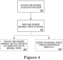
- Figure 4 shows a flowchart of a method of moving one or more reticle contacts according to an embodiment.
- the method 400 includes activating one or more latches located in a pod door, attaching the pod door to a pod dome 402.
- the method 400 further includes driving one or more movable posts to extend in a direction having a component perpendicular to a plane of the pod door 404.
- the method 400 also includes contacting one or more movable reticle contacts of a baseplate via the one or more movable posts 406.
- One or more latches located in a pod door are activated attaching the pod door to a pod dome at 402.
- the pod door and the pod dome may form an outer portion of a reticle pod.
- the pod door and the pod dome may define an internal space.
- the pod door and the pod dome may be, for example, pod door 102 and pod door 104 described above and shown in Figure 1 .
- Activating the latch at 402 causes the latch to move into a deployed position where the latch secures the pod door to the pod dome.
- An inner portion of the reticle pod including a cover and a baseplate, such as cover 106 and baseplate 108 or baseplate 200 may be included within the internal space.
- the one or more latches may be activated 402 automatically by attaching the pod door to the pod dome.
- the one or more latches may be activated 402 by mechanically operating a knob, slider, or other feature, either manually or via another device. Activation of the one or more latches at 402 causes the latches to move. Movement of the latches caused by activation of 402 may cause contact between the latches and one or more actuator mechanism or direct contact with one or more movable posts.
- One or more movable posts are driven to extend in a direction having a component perpendicular to a plane of the pod door at 404.
- the movable posts are driven as a result of the activation of the one or more latches at 402.
- the movable posts may be connected to the pod door.
- the movable posts may be positioned so that each corresponds to a reticle contact included in a baseplate that is included in the reticle pod, the baseplate being part of the inner portion of the reticle pod in an internal space defined by the pod door and the pod dome.
- the movable posts may be driven via their contact with the one or more latches or with one or more actuators.
- the one or more actuators may include, for example, a rocker arm, a camming surface, or a sliding surface.
- one or more of the movable posts are driven by contact between the movable post and a sliding surface included on the latch.
- the sliding surface may have a wedge shape.
- the wedge shape of the sliding surface may drive the movement of the movable post in the direction having a component perpendicular to a plane of the pod door.
- the direction having a component perpendicular to a plane of the pod door may be a direction towards the baseplate of an inner part of the reticle pod when the reticle pod is assembled.
- a rocker arm is actuated by the latch, and the rocker arm drives the one or more movable posts.
- a camming surface of each actuator contacts the latch, with movement of the latch causing camming that results in movement of the actuator that in turn drives the one or more movable posts are driven to extend in a direction having a component perpendicular to a plane of the pod door.
- one or more movable reticle contacts of a baseplate are contacted via the one or more movable posts 406.
- the one or more movable reticle contacts in the baseplate may be moved towards a cover that is part of the inner portion of the reticle pod.
- the movable reticle contacts may be moved towards a cover joined to the baseplate. Movement of the movable reticle contacts may be to a position such that a reticle located between the cover and the baseplate would be clamped between the movable reticle contact and reticle contacts on a cover joined to the baseplate.
- This clamping may be such that it secures the reticle while the cover and baseplate are joined, while combined reticle cover and baseplate are located within the pod door and pod dome, and while the pod door is latched to the pod dome.
- the reticle contacts may be retained in this position by the movable posts while the pod door remains secured to the pod dome via the latch actuated at 402.
- movement of the one or more movable reticle contacts may be movement of each of the movable reticle contacts towards a reticle contact on the cover, opposite each of the one or more movable reticle contacts.
- movement of the one or more movable reticle contacts is towards the cover, and reticle contacts included on the cover are offset from the movable reticle contacts on the baseplate, such that the respective reticle contacts on the cover and the baseplate are not opposite one another.
- step 406 may be replaced by extending the movable posts through apertures in the baseplate 408.
- the baseplate includes an aperture for each of the one or more movable posts.
- the movable posts are driven to pass through the apertures when the one or more movable posts are driven to extend in a direction having a component perpendicular to a plane of the pod door at 404.
- the movable posts may be pushed through a seal configured to form a seal at the aperture when the movable post is extending through the aperture.
- the seal may be, as a non-limiting example, an O-ring.
- the movable posts may include a contact surface made of a compatible material.
- Aspect 2 The reticle pod according to aspect 1, wherein each of the one or more movable reticle contacts are retained in the baseplate via a flexible member.
- Aspect 3 The reticle pod according to aspect 2, wherein when the flexible is at rest, the movable reticle contact is at a distance from at least one of the one or more cover reticle contacts that is greater than a thickness of a reticle to be stored in the reticle pod.
- Aspect 4 The reticle pod according to any of aspects 1-3, wherein the one or more latches are each movable in a direction in plane with pod door.
- Aspect 7 The reticle pod according to any of aspects 1-6, wherein the pod dome includes one or more projections that contact the cover when the inner portion is located within the outer portion and the pod door is fixed to the pod dome.
- Aspect 8 The reticle pod according to any of aspects 1-7, wherein each of the cover reticle contacts includes a polymer material.
- each of the movable reticle contacts includes a polymer material.
- Aspect 11 The reticle pod according to any of aspects 1-10, wherein the one or more movable reticle contacts includes four movable reticle contacts.
- Aspect 12 The reticle pod according to any of aspects 1-11, wherein each of the one or more movable reticle contacts is opposite one of the one or more cover reticle contacts when the cover is engaged with the baseplate.
- Aspect 14 The reticle pod according to any of aspects 1-13, wherein each of the one or more movable reticle contacts is at a position corresponding to a corner of a reticle.
- a method of moving contacts within a pod comprising:
- Aspect 18 The method according to any of aspects 15-17, further comprising placing a reticle on a baseplate of the pod, joining the baseplate of the pod to a cover of the pod, and placing the joined baseplate and cover into a space within the pod dome.
- Aspect 19 The method according to aspect 18, wherein the joined baseplate and cover are in contact with one or more projections from the pod dome when placed within the pod dome.
- Aspect 20 The method according to any of aspects 15-19, wherein at least three movable posts are driven via the one or more latches.
- Aspect 21 The method according to any of aspects 15-20, wherein the cover includes one or more cover reticle contacts, each of the cover reticle contacts opposite one of the movable reticle contacts.
- Aspect 22 The method according to any of aspects 15-21, wherein the cover includes one or more cover reticle contacts, each of the cover reticle contacts offset from the movable reticle contacts.
- a reticle pod comprising:
- Aspect 25 The reticle pod according to any of aspects 23-24, wherein the one or more latches each include a sliding surface, a rocker arm, or a camming surface in contact with a surface of one of the one or more movable posts.
- Aspect 26 The reticle pod according to any of aspects 23-25, wherein the pod dome includes one or more projections that contact the cover when the inner portion is located within the outer portion and the pod door is fixed to the pod dome.
- Aspect 27 The reticle pod according to any of aspects 23-26, wherein each of the cover reticle contacts includes a polymer material.
- Aspect 28 The reticle pod according to any of aspects 23-27, wherein each of the movable posts includes a polymer material.
- Aspect 29 The reticle pod according to any of aspects 23-28, wherein the one or more movable posts includes three or more movable posts.
- Aspect 30 The reticle pod according to any of aspects 23-29, wherein the one or more movable posts includes four movable posts.
- Aspect 31 The reticle pod according to any of aspects 23-30, wherein each of the one or more apertures is opposite one of the one or more cover reticle contacts when the cover and the baseplate are connected to one another.
- Aspect 32 The reticle pod according to any of aspects 23-31, wherein each of the one or more apertures are offset from the one or more cover reticle contacts when the cover and the baseplate are connected to one another.
- Aspect 33 The reticle pod according to any of aspects 23-32, wherein each of the one or more apertures is at a position corresponding to a corner of a reticle.
- Aspect 36 The method according to aspect 35, wherein activating the one or more latches comprises moving the one or more latches in one or more directions that are parallel to a plane of the pod door.
- Aspect 38 The method according to any of aspects 35-37, further comprising placing a reticle on a baseplate of the pod, joining the baseplate of the pod to a cover of the pod, and placing the joined baseplate and cover into a space within the pod dome.
- Aspect 39 The method according to aspect 38, wherein the joined baseplate and cover are in contact with one or more projections from the pod dome when placed within the pod dome.
Landscapes
- Physics & Mathematics (AREA)
- General Physics & Mathematics (AREA)
- Container, Conveyance, Adherence, Positioning, Of Wafer (AREA)
- Preparing Plates And Mask In Photomechanical Process (AREA)
- Exposure And Positioning Against Photoresist Photosensitive Materials (AREA)
- Packaging Frangible Articles (AREA)
Abstract
Description
- This application claims the benefit of and priority to
U.S. Provisional Application No. 62/953,326, filed on December 24, 2019 - This disclosure is directed to reticle pods and more particularly, to reticle pods including movable reticle retention features for retaining a reticle at a desired position.
- Reticle pods are used for storage and transport of reticles as well as processing, particularly transport of reticles to and from processing tools such as photolithography devices. Reticle pods include, for example, Extreme Ultraviolet (EUV) pods for use with EUV photolithography tools. Reticle pods are constructed to reduce and/or prevent contamination or physical damage to the reticles contained therein during movement, handling, and processing of the reticles. Reticle pods may include an outer pod and an inner pod within the outer pod. The inner pod may include a baseplate and a cover, which contain the reticle. The outer pod includes a pod door and a pod dome, which contains the inner pod.
- This disclosure is directed to reticle pods including movable retention features for retaining the reticle located on the baseplate.
- Movable retention features allow a reticle to be securely positioned within a reticle pod, and thus less susceptible to shocks during handling or transit. By actuating such features through latches located in a door of the reticle pod, the reticle may be properly placed within the pod without interference from security features prior to final closure of the reticle pod, and secured when the pod is closed for transport, storage, or processing. Securing the reticle may limit or prevent damage to the reticle including shock incidents, particle generation from contact of the reticle and the interior of the pod, and the like.
- A reticle pod embodiment includes an inner portion including a cover and a baseplate. The cover includes one or more cover reticle contacts joined to the cover and the baseplate includes one or more movable reticle contacts, the one or more movable reticle contacts each configured to be movable in a direction having a component perpendicular to the plane of the baseplate. The reticle pod includes an outer portion comprising a pod dome and a pod door, wherein the pod door includes one or more movable posts and one or more latches configured to drive the one or more movable posts. When the inner portion is located within the outer portion and the pod door is fixed to the pod dome, the one or more movable posts contact the one or more movable reticle contacts such that the one or more movable reticle contacts are moved towards the cover.
- In an embodiment, each of the one or more movable reticle contacts are retained in the baseplate via a flexible member.
- In an embodiment, when the flexible member is at rest, the movable reticle contact is at a distance from at least one of the one or more cover reticle contacts that is greater than a thickness of a reticle to be stored in the reticle pod.
- In an embodiment, the one or more latches are each movable in a direction in plane with pod door.
- In an embodiment, the one or more latches each include a sliding surface, a rocker arm, or a camming surface in contact with a surface of one of the one or more movable posts.
- In an embodiment, the one or more movable reticle contacts are each configured to be movable in a direction perpendicular to the plane of the baseplate.
- In an embodiment, the pod dome includes one or more projections that contact the cover when the inner portion is located within the outer portion and the pod door is fixed to the pod dome.
- In an embodiment, each of the cover reticle contacts includes a polymer material.
- In an embodiment, each of the movable reticle contacts includes a polymer material.
- In an embodiment, the one or more movable reticle contacts includes three or more movable reticle contacts.
- In an embodiment, the one or more movable reticle contacts includes four movable reticle contacts.
- In an embodiment, each of the one or more movable reticle contacts is opposite one of the one or more cover reticle contacts when the cover and the baseplate are connected to one another.
- In an embodiment, each of the one or more movable reticle contacts are offset from the one or more cover reticle contacts when the cover and the baseplate are connected to one another.
- In an embodiment, each of the one or more movable reticle contacts is at a position corresponding to a corner of a reticle.
- In an embodiment, a method of moving contacts within a pod includes activating one or more latches located in a pod door by attaching the pod door to a pod dome and driving, via the one or more latches, one or more movable posts to extend in a direction having a component perpendicular to a plane of the pod door. Each of the one or more movable posts contacts a movable reticle contact of a baseplate located within the pod door and the pod dome, such that the movable reticle contact moves in a direction having a component perpendicular to the plane of the baseplate and towards a cover located within the pod door and the pod dome.
- In an embodiment, activating the one or more latches comprises moving the one or more latches in one or more directions that are parallel to a plane of the pod door.
- In an embodiment, driving, via the one or more latch, the movable post comprises a camming surface on each of the one or more latches contacting one of the one or more movable posts.
- In an embodiment, the method further includes further comprising placing the reticle on a baseplate of the pod, joining the baseplate of the pod to a cover of the pod, and placing the joined baseplate and cover into a space within the pod dome. In an embodiment, the joined baseplate and cover are in contact with one or more projections from the pod dome when placed within the pod dome.
- In an embodiment, at least three movable posts are driven via the one or more latches
- In an embodiment, the cover includes one or more cover reticle contacts, each of the cover reticle contacts opposite one of the movable reticle contacts.
- In an embodiment, the cover includes one or more cover reticle contacts, each of the cover reticle contacts offset from the movable reticle contacts.
- In an embodiment, a reticle pod includes an inner portion comprising a cover and a baseplate. The cover includes one or more cover reticle contacts joined to the cover and the baseplate includes one or more apertures. The reticle pod includes an outer portion comprising a pod dome and a pod door. The pod door includes one or more movable posts and one or more latches configured to drive the one or more movable posts. When the inner portion is located within the outer portion and the pod door is fixed to the pod dome, the one or more movable posts extend through the one or more apertures into the inner portion.
- In an embodiment, the one or more latches are each movable in a direction in plane with pod door.
- In an embodiment, the one or more latches each include a sliding surface, a rocker arm, or a camming surface in contact with a surface of one of the one or more movable posts.
- In an embodiment, the pod dome includes one or more projections that contact the cover when the inner portion is located within the outer portion and the pod door is fixed to the pod dome.
- In an embodiment, each of the cover reticle contacts includes a polymer material.
- In an embodiment, each of the movable posts includes a polymer material.
- In an embodiment, the one or more movable posts includes three or more movable posts.
- In an embodiment, the one or more movable posts includes four movable posts.
- In an embodiment, each of the one or more apertures is opposite one of the one or more cover reticle contacts when the cover and the baseplate are connected to one another.
- In an embodiment, each of the one or more apertures are offset from the one or more cover reticle contacts when the cover and the baseplate are connected to one another.
- In an embodiment, each of the one or more apertures is at a position corresponding to a corner of a reticle.
- In an embodiment, the reticle pod further includes a seal disposed in each of the apertures.
- In an embodiment, a method of providing contacts within a pod includes activating one or more latches located in a pod door by attaching the pod door to a pod dome using a cam, and driving, via the one or more latches or the cam, one or more movable posts to extend in a direction having a component perpendicular to a plane of the pod door. Each of the one or more movable posts extend through a baseplate into an inner portion of the pod when driven via the one or more latches or the cam.
- In an embodiment, activating the one or more latches includes moving the one or more latches in one or more directions that are parallel to a plane of the pod door.
- In an embodiment, driving, via the one or more latch, the movable post includes a camming surface on each of the one or more latches contacting one of the one or more movable posts.
- In an embodiment, the method further includes placing a reticle on a baseplate of the pod, joining the baseplate of the pod to a cover of the pod, and placing the joined baseplate and cover into a space within the pod dome.
- In an embodiment, the joined baseplate and cover are in contact with one or more projections from the pod dome when placed within the pod dome.
- In an embodiment, at least three movable posts are driven via the one or more latches.
- In an embodiment, the cover includes one or more cover reticle contacts, each of the cover reticle contacts opposite one of the movable posts.
- In an embodiment, the cover includes one or more cover reticle contacts, each of the cover reticle contacts offset from the movable posts.
- In an embodiment, the method further includes forming a seal between the baseplate and the one or more movable posts.
- The disclosure may be more completely understood in consideration of the following description of various illustrative embodiments in connection with the accompanying drawings.
-
Figure 1 shows a reticle pod according to an embodiment including a partial sectional view. -
Figure 1A shows the partial sectional view ofFigure 1 expanded to provide further detail. -
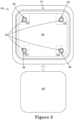
Figure 2 shows a plan view of a baseplate of a reticle pod according to an embodiment. -
Figure 3 shows a sectional view of a reticle pod according to an embodiment. -
Figure 4 shows a flowchart of a method of moving one or more reticle contacts according to an embodiment. - While the disclosure is amenable to various modifications and alternative forms, specifics thereof have been shown by way of example in the drawings and will be described in detail. It should be understood, however, that the intention is not to limit aspects of the disclosure to the particular illustrative embodiments described. On the contrary, the intention is to cover all modifications, equivalents, and alternatives falling within the spirit and scope of the disclosure.
- The following detailed description should be read with reference to the drawings in which similar elements in different drawings are numbered the same. The detailed description and the drawings, which are not necessarily to scale, depict illustrative embodiments and are not intended to limit the scope of the invention. The illustrative embodiments depicted are intended only as exemplary. Selected features of any illustrative embodiment may be incorporated into an additional embodiment unless clearly stated to the contrary.
- As used in this specification and the appended claims, the singular forms "a", "an", and "the" include plural referents unless the content clearly dictates otherwise. As used in this specification and the appended claims, the term "or" is generally employed in its sense including "and/or" unless the content clearly dictates otherwise.
- The term "about" generally refers to a range of numbers that is considered equivalent to the recited value (e.g., having the same function or result). In many instances, the term "about" may include numbers that are rounded to the nearest significant figure.
- This disclosure is directed to reticle pods and more particularly, to reticle pods including movable reticle retention features for retaining a reticle.
-
Figure 1 shows areticle pod 100 according to an embodiment including a partial sectional view, andFigure 1A shows the partial sectional view ofFigure 1 expanded to provide further detail. -
Reticle pod 100 includes anouter portion 122 includingpod dome 102 andpod door 104.Reticle pod 100 also includes aninner portion 124 includingbaseplate 106 andcover 108.Baseplate 106 includesmovable reticle contacts 110. Cover 108 includescover reticle contacts 112.Movable reticle contacts 110 are contacted bymovable posts 114 when the inner and outer portions ofreticle pod 100 are assembled andpod door 104 is joined topod dome 102.Movable posts 114 are in contact withactuating mechanisms 116, which are driven bylatch 118 of thepod door 104. -
Pod dome 102 is part of theouter portion 122 ofreticle pod 100.Pod dome 102 may include one or more features configured to contactcover 108 when thereticle pod 100 is assembled.Pod dome 102 includes an internal space. The internal space may include a first internal space sized to accommodate theinner portion 124 ofreticle pod 100 and a second space at an end ofpod dome 102 configured to accommodatepod door 104. The second space may be defined by a lip. The portion ofpod dome 102 surrounding the second space may include one or more slots or other openings configured to receive an end oflatch 118.Pod dome 102 may be made of a polymer material. -
Pod door 104 is another part of theouter portion 122 ofreticle pod 100.Pod door 104 is configured to be combined withpod dome 102 to form theouter portion 122 of thereticle pod 100. Thepod door 104 may be sized such that it fits in a space ofpod dome 102 such that it closes an end ofpod dome 104.Pod door 104 includeslatch 118 andactuating mechanisms 116.Pod door 104 further is connected tomovable posts 114.Pod door 104 may be joined topod dome 102 by one ormore latches 118 when thelatches 118 are in a deployed position.Pod door 104 may be removable frompod dome 102 whenlatches 118 are not in the deployed position. - When
pod dome 102 andpod door 104 are joined together, thepod dome 102 andpod door 104 together define an internal space capable of accommodating theinner portion 124 ofreticle pod 100 includingbaseplate 106 andcover 108. Thepod dome 102 and thepod door 104 may include feature projecting into the internal space and configured to contact thebaseplate 106 or cover 108 to hold thebaseplate 106 or cover 108 in position when thereticle pod 100 is assembled. -
Baseplate 106 is part of theinner portion 124 ofreticle pod 100. Whenreticle pod 100 is assembled,baseplate 106 may be supported bypod door 104. Thebaseplate 106 typically forms the lower part of theinner portion 124 ofreticle pod 100. Thebaseplate 106 may be configured such that a reticle may rest onbaseplate 106.Baseplate 106 may be made of a metal or alloy. In an embodiment,baseplate 106 includes aluminum. In an embodiment,baseplate 106 can include reticle contacts, the reticle contacts having a height that is smaller than the height of themovable reticle contacts 110 when themovable reticle contacts 110 are extended. -
Movable reticle contacts 110 are movably connected to thebaseplate 106. The movable connection may be a connection via a resilient material. Non-limiting examples of the movable connection include a metal spring formed inbaseplate 106, a spring separate from but connected tobaseplate 106, a polymer such as rubber joining the movable reticle, or any other such movable connection. Themovable reticle contacts 110 are configured to move in a direction having a component perpendicular to the plane ofbaseplate 106. In an embodiment the movable reticle contacts are configured to move in a direction perpendicular to the plane ofbaseplate 106. Whenbaseplate 106 and cover 108 are joined, the movement ofmovable reticle contacts 110 is such that the movable reticle contacts move in a direction towards or away fromcover 108.Movable reticle contacts 110 may include material compatible with a reticle material. Compatible materials include materials that provide minimal or no particle generation when in contact with the reticle material, and which cannot scratch or otherwise damage the reticle material. In an embodiment, the compatible material is a polymer material. In an embodiment, the entiremovable reticle contact 110 is made of the compatible material. In an embodiment, the movable reticle contact includes a contact point including the compatible material. Non-limiting examples of the compatible material include polyether-ether-ketone (PEEK), polyaryl-ether-ketone (PAEK), polyamide-imide (PAI), polyether-imide (PEI), and conductive polymers. - Cover 108 is another part of the
inner portion 124 ofreticle pod 100. Cover 108 may form the upper part of theinner portion 124 ofreticle pod 100 when theinner portion 124 is assembled frombaseplate 106 andcover 108. Cover 108 is configured to be joined tobaseplate 106, for example by having matching or mechanically compatible features. Whencover 108 is joined tobaseplate 106,cover 108 andbaseplate 106 define an internal space configured to accommodate a reticle. Cover 108 may be made of a metal or alloy, for example, aluminum. Cover 108 may include one or morecover reticle contacts 112. In an embodiment, when theinner portion 124 of the reticle pod is placed withinpod dome 102 andpod door 104, andpod door 104 is joined topod dome 102,cover 108 is contacted bypod dome 102. -
Cover reticle contacts 112 are contacts joined to cover 108 of theinner portion 124 ofreticle pod 100. In an embodiment, coverreticle contacts 112 are fixed to the inside of the cover such that they face thebaseplate 106 when theinner portion 124 ofreticle pod 100 is assembled. In an embodiment, coverreticle contacts 112 are fixed in position. Non-limiting examples of the fixation ofcover reticle contacts 112 include pressing, mechanical fastening, or being integral parts of thecover 108, for example being directly machined intocover 108. In an embodiment, coverreticle contacts 112 are movable, for example being retained by resilient members similar to themovable reticle contacts 110 joined tobaseplate 106.Cover reticle contacts 112 may be positioned such that when the baseplate and the cover are assembled, the cover reticle contacts each oppose one of themovable reticle contacts 110. In an embodiment, coverreticle contacts 112 may be positioned such that they are offset from themovable reticle contacts 110; i.e. that the cover reticle contacts and themovable reticle contacts 110 are not opposite one another. When themovable reticle contacts 110 and thecover reticle contacts 112 are offset from one another and the baseplate and cover are assembled together, thecover reticle contacts 112 are not above themovable reticle contacts 110. In an embodiment, thereticle pod 100 includes at least threecover reticle contacts 112. In an embodiment, thereticle pod 100 includes fourcover reticle contacts 112. In an embodiment, thereticle pod 100 includes eightcover reticle contacts 112.Cover reticle contacts 112 include a material compatible with the reticle material. Compatible materials include materials that provide minimal or no particle generation when in contact with the reticle material, and which cannot scratch or otherwise damage the reticle material. In an embodiment, the compatible material is a polymer material.Cover reticle contacts 112 may include the compatible material at least at a contact point configured to contact a reticle whenreticle pod 100 is assembled. In an embodiment, thecover reticle contacts 112 are entirely made of a polymer material suitable for contacting the reticle. Non-limiting examples of the compatible material include polyether-ether-ketone (PEEK), polyaryl-ether-ketone (PAEK), polyamide-imide (PAI), polyether-imide (PEI), and conductive polymers. -
Movable posts 114 are one or more posts located on the pod door that are configured to contact themovable reticle contacts 110 whenreticle pod 100 is assembled andpod door 104 is fixed topod dome 102 vialatch 118.Movable posts 114 protrude from a surface ofpod door 104 facingbaseplate 106 at least whenpod door 104 is fixed topod dome 102 vialatch 118.Movable posts 114 may be flush withpod door 104, recessed intopod door 104, or protruding a smaller distance frompod door 104 whenpod door 104 is not fixed topod dome 102.Movable posts 114 are movable in a direction having a component in a vertical direction with respect to the surface ofpod door 104 facingbaseplate 106 whenreticle pod 100 is assembled. In an embodiment,movable posts 114 are movable in the vertical direction with respect to the surface ofpod door 104 facingbaseplate 106 whenreticle pod 100 is assembled. The number ofmovable posts 114 may be the same as the number ofmovable reticle contacts 110. - In an alternative embodiment,
movable posts 114 may have a length such that they extend through the baseplate when thereticle pod 100 is assembled and latch 118 closed. In this embodiment, apertures are formed in thebaseplate 106, for example at the locations of themovable reticle contacts 110. The apertures may be the openings wheremovable reticle contacts 110 are disposed inbaseplate 106. In this embodiment, the movable posts may include material compatible with a reticle material. Compatible materials include materials that provide minimal or no particle generation when in contact with the reticle material, and which cannot scratch or otherwise damage the reticle material. In an embodiment, the compatible material is a polymer material. In an embodiment, themovable post 114 is made of the compatible material. In an embodiment, themovable post 114 includes a contact point including the compatible material. Non-limiting examples of the compatible material include polyether-ether-ketone (PEEK), polyaryl-ether-ketone (PAEK), polyamide-imide (PAI), polyether-imide (PEI), and conductive polymers. In this embodiment, the apertures inbaseplate 106 may include seals configured to form a seal around themovable post 114 when themovable post 114 extends through the aperture. The seals may be, for example, O-rings. -
Actuating mechanism 116 includes one or more components located within thepod door 104 and configured to drive the movable posts based on movement oflatch 118. Theactuating mechanism 116 is any one or more mechanisms to translate movement of thelatch 118 to movement of themovable posts 114. In an embodiment,actuating mechanism 116 includes one or more sliding surfaces formed onlatch 118. In an embodiment,actuating mechanism 116 includes one or more rocker arms. In an embodiment,actuating mechanism 116 includes one or more camming surfaces configured to contact thelatch 118 such that movement of thelatch 118 causes actuating mechanism to slide, rock, or cam with respect to themovable posts 114. -
Latch 118 is a latch securing thepod door 104 topod dome 102.Latch 118 may include alatch pin 120 configured to, in a deployed position, engagepod dome 104 to securepod door 102. In an embodiment, thelatch 118 further includes a rotational actuator (not shown) configured to extend and retract thelatch pin 120. In an embodiment, the rotational actuator includes a cam, for example, thelatch cam 308 shown inFigure 3 and discussed below. In an embodiment, operation of the rotational actuator drives the one or moremovable posts 114. In an embodiment, operation of the rotational actuator can cause lifting of at least a portion of each of the latch pins. In a retracted position, latch 118 may be entirely withinpod door 104.Latch 118 may include one or more sliding surfaces that function asactuating mechanism 116.Latch 118 may include one or more engagement features configured to interact withactuating mechanism 116, such as one or more surfaces configured to contact a rocker arm, one or more cams or camming surfaces configured to contact camming surfaces ofactuating mechanism 118, or other suitable features for contactingactuating mechanism 116. The engagement features oflatch 118 may contact theactuating mechanism 116 when thelatch 118 is in the deployed position. In an embodiment,pod door 104 includes a knob, switch, toggle, or other such suitable control to move the latch between deployed and retracted states. In an embodiment,latch 118 is configured to be deployed whenpod door 104 is pressed againstpod dome 102. -
Figure 2 shows a plan view of abaseplate 200 of a reticle pod according to an embodiment.Baseplate 200 includes aspace 202 for areticle 208 andmovable reticle contacts 204. Each ofmovable reticle contacts 204 is retained via aflexible member 206. Thereticle contacts 204 are located at positions that would correspond to corners of thereticle 208 when that reticle is placed within the space for thereticle 202. - Space for the
reticle 202 is a portion of the baseplate where a reticle may be placed.Reticle 208 is illustrated to show the fit of thereticle 208 within space for thereticle 202. In an embodiment, space for thereticle 202 may be defined byside walls 210. In an embodiment, the space for thereticle 202 may be a portion of the surface of the baseplate that is surrounded by the cover when the cover is attached to thebaseplate 200. The shape of space for thereticle 202 may be configured to follow the shape of thereticle 208, for example being square for a square reticle or circular for a circular reticle. The space for thereticle 202 may be sized such that it is slightly larger than thereticle 208 to be placed within. -
Movable reticle contacts 204 are distributed alongbaseplate 200, within the space for thereticle 202. In an embodiment, the movable reticle contacts are located in theareas 212 of the space for thereticle 202 corresponding to corners of thereticle 208. When thereticle 208 is placed within the space for thereticle 202, it may rest on themovable reticle contacts 204.Movable reticle contacts 204 may be made of a suitable material for contacting and retaining thereticle 208 in position, such as a polymer material. The material ofmovable reticle contacts 204 may be compatible with the material ofreticle 208, such that contact between them does not generate particles or cause any scratches or damage to thereticle 208. In an embodiment, movable reticle contacts include a polymer material at least at the point where they are configured to contactreticle 208.Reticle 208 may be placed onmovable reticle contacts 204 when assembling a reticlepod including baseplate 200.Movable reticle contacts 204 may have a standard position and a retention position, where themovable reticle contacts 204 are configured to clamp thereticle 208 to another feature such as reticle contacts on a cover of the reticlepod including baseplate 200. The standard position may be taken by themovable reticle contacts 204 when the pod door is not secured to the pod dome for the reticlepod including baseplate 200. In the standard position, thereticle 208 may rest on themovable reticle contacts 204 when thereticle 208 is placed into the space for thereticle 202. In the standard position, when the pod door is not secured to the pod dome, there may be a gap between an upper surface of thereticle 208 and all features of the cover including any reticle contacts on the cover. -
Flexible member 206 retainsmovable reticle contact 204 tobaseplate 200.Flexible member 206 may be, for example, a metal spring, a resilient polymer material, or another suitable connection joiningreticle contacts 204 tobaseplate 200 such that themovable reticle contacts 204 are movable with respect to thebaseplate 200. As shown inFigure 2 , theflexible member 206 may be a metal spring formed integrally with thebaseplate 200, for example a metal spring defined by removal of material and providing a connection point for themovable reticle contact 204 such as a groove or hole into which a portion of the movable reticle contact may be inserted.Flexible member 206 may include a resilient polymer, such as rubber.Flexible member 206 may include resilient polymer formed integrally with themovable reticle contact 204, such as posts, tabs, or a ring of resilient polymer extending from themovable reticle contact 204 to one or more securing points on thebaseplate 200.Flexible member 200 may be elastic such that it moves or retains movable reticle contact in the standard position in the absence of other forces, and allows movement of themovable reticle contact 204 into the retention position when force is applied to themovable reticle contact 204 or theflexible member 206. - One or both of each of the
movable reticle contacts 204 orflexible member 206 include a surface presented on the side of thebaseplate 200 opposite the side visible inFigure 2 . This surface of one or both of each of themovable reticle contacts 204 orflexible member 206 may be contacted by a movable post included on a pod door of a reticlepod including baseplate 200. Contact with the movable post may cause themovable reticle contacts 204 to be moved in a direction having a component perpendicular to the plane ofbaseplate 200, such that themovable reticle contacts 204 are moved towards a cover that is placed on the baseplate. The movement of themovable reticle contacts 204 may cause areticle 208 to be clamped between and reticle contacts on the cover. This clamping ofreticle 208 may secure the position ofreticle 208 to restrict or prevent movement of the reticle when the reticlepod including baseplate 200 is fully assembled and the pod dome is secured to the pod door. The securing of the pod dome to the pod door may be via one or more latches in the pod door. These one or more latches may actuate the movable posts and drive them to contact one or both of each of themovable reticle contacts 204 orflexible member 206. The one or more latches may thus cause movement of themovable reticle contacts 204 between the standard position and the retention position. -
Figure 3 shows a sectional view of a reticle pod according to an embodiment.Reticle pod 300 includes anouter portion 302 including apod dome 304 and apod door 306.Pod door 306 includes alatch cam 308 and alatch arm 310.Latch arm 310 includes acontact point 312 in contact withlatch cam 308.Latch arm 310 also contactsmovable post 314 atend 316 of themovable post 314.Movable post 314 contacts movable reticle contact 318. Movable reticle contact 318 extends throughbaseplate 320.Baseplate 320 and cover 322 form theinner portion 324 of thereticle pod 300. Cover 322 includescover reticle contacts 326. Whenreticle pod 300 is assembled,cover reticle contacts 326 and movable reticle contacts 318 are configured to clamp areticle 328 within theinner portion 324 of thereticle pod 300. -
Pod dome 304 is part ofouter portion 302 ofreticle pod 300.Pod dome 304 in part defines an internal space capable of accommodating theinner portion 324 of thereticle pod 300.Pod door 306 is configured to be joined withpod dome 304 to form theouter portion 302 and fully define the internal space capable of accommodating theinner portion 324.Pod door 306 can be joined topod dome 304 by a latch includinglatch cam 308 and two ormore latch arms 310. -
Latch cam 308 is a cam configured to actuate latcharms 310 when thelatch cam 308 is rotated.Latch cam 308 can be joined to a handle allowing a user to drive rotation of thelatch cam 308. Thelatch cam 308 can include one or more camming surfaces 330 configured to engagecontact points 312 formed onlatch arms 310 to move latcharms 310. In an embodiment, the camming surfaces 330 drive the ends oflatch arms 310 havingcontact points 312 upwards as they drive thelatch arms 310 into extended positions. -
Latch arm 310 is an arm configured to engage withpod dome 304 to securepod door 306 to thepod dome 304 when in an extended position.Latch arm 310 can also be in a retracted position where it does not engage withpod dome 304.Latch arm 310 can be driven to the retracted and extended positions by the operation of thelatch cam 308.Contact point 312 is a point onlatch arm 310 that engages withlatch cam 308.Contact point 312 can be formed integrally withlatch arm 310, such as a projection fromlatch arm 310. Engagement ofcontact point 312 withlatch cam 308 can drivelatch arm 310 to move between extended and retracted positions. Engagement ofcontact point 312 withlatch cam 308 can further cause tilting of thelatch arm 310, for example lifting an end of thelatch arm 310 that includescontact point 312 when thelatch cam 308 drives thelatch arm 310 to the extended position, as visible inFigure 3 . -
Movable posts 314 are one or more posts located on the pod door that are configured to contact the movable reticle contacts 318 whenreticle pod 300 is assembled andpod door 304 is fixed topod dome 306 via the latch includinglatch cam 308 andlatch arm 310.Movable posts 314 protrude from a surface ofpod door 306 facingbaseplate 320 at least whenpod door 306 is fixed topod dome 304 via the latch includinglatch cam 308 andlatch arm 310.Movable posts 314 may be flush withpod door 306, recessed intopod door 306, or protruding a smaller distance frompod door 306 whenpod door 306 is not fixed topod dome 304.Movable posts 314 are movable in a direction having a component in a vertical direction with respect to the surface ofpod door 306 facingbaseplate 320 whenreticle pod 300 is assembled. In an embodiment,movable posts 314 are movable in the vertical direction with respect to the surface ofpod door 306 facingbaseplate 320 whenreticle pod 300 is assembled. The number ofmovable posts 314 may be the same as the number of movable reticle contacts 318. In an embodiment, the vertical direction is perpendicular to the plane ofpod door 306. -
Movable post 314 includes anend 316 opposite the movable reticle contact 318. Theend 316 can contact thelatch arm 310 such that at least a component of movement of thelatch arm 310 is transferred tomovable post 314. In an embodiment, the component of movement of thelatch arm 310 that is transferred tomovable post 314 is the component that is perpendicular to the plane ofpod door 306. The contact of the can drivemovable post 314 to change positions based on the position of thelatch arm 310, for example driving the movable post towards thebaseplate 320 when thelatch cam 308 is rotated to extend thelatch arm 310 and in turn raises the end of the latch arm including thecontact point 312. - Movable reticle contact 318 is movably connected to the
baseplate 320. The movable connection may be a connection via a resilient material. Non-limiting examples of the movable connection include a metal spring formed inbaseplate 320, a spring separate from but connected tobaseplate 320, a polymer such as rubber joining the movable reticle, or any other such movable connection. The movable reticle contacts 318 are configured to move in a direction having a component perpendicular to the plane ofbaseplate 320. In an embodiment the movable reticle contacts are configured to move in a direction perpendicular to the plane ofbaseplate 320. Whenbaseplate 320 and cover 322 are joined, the movement of movable reticle contacts 318 is such that the movable reticle contacts move in a direction towards or away fromcover 322. Movable reticle contacts 318 may include material compatible with a reticle material. Compatible materials include materials that provide minimal or no particle generation when in contact with the reticle material, and which cannot scratch or otherwise damage the reticle material. In an embodiment, the compatible material is a polymer material. In an embodiment, the entire movable reticle contact 318 is made of the compatible material. In an embodiment, the movable reticle contact includes a contact point including the compatible material. Non-limiting examples of the compatible material include polyether-ether-ketone (PEEK), polyaryl-ether-ketone (PAEK), polyamide-imide (PAI), polyether-imide (PEI), and conductive polymers. -
Baseplate 320 is part of theinner portion 324 ofreticle pod 300. Whenreticle pod 300 is assembled,baseplate 320 may be supported bypod door 306. Thebaseplate 320 typically forms the lower part of theinner portion 324 ofreticle pod 300. Thebaseplate 320 may be configured such that areticle 328 may rest onbaseplate 320.Baseplate 320 may be made of a metal or alloy. In an embodiment,baseplate 320 includes aluminum. In an embodiment,baseplate 320 can include reticle contacts, the reticle contacts having a height that is smaller than the height of the movable reticle contacts 318 when the movable reticle contacts 318 are extended. - Cover 322 is another part of the
inner portion 324 ofreticle pod 300. Cover 322 may form the upper part of theinner portion 324 ofreticle pod 300 when theinner portion 324 is assembled frombaseplate 320 andcover 322. Cover 322 is configured to be joined tobaseplate 320, for example by having matching or mechanically compatible features. Whencover 322 is joined tobaseplate 320,cover 322 andbaseplate 320 define an internal space configured to accommodate areticle 328. Cover 322 may be made of a metal or alloy, for example, aluminum. Cover 322 may include one or morecover reticle contacts 326. In an embodiment, when theinner portion 324 of thereticle pod 300 is placed withinpod dome 304 andpod door 306, andpod door 306 is joined topod dome 304,cover 322 is contacted bypod dome 304. -
Cover reticle contacts 326 are contacts joined to cover 322 of theinner portion 324 ofreticle pod 300. In an embodiment, coverreticle contacts 326 are fixed to the inside of the cover such that they face thebaseplate 320 when theinner portion 324 ofreticle pod 300 is assembled. In an embodiment, coverreticle contacts 326 are fixed in position. Non-limiting examples of the fixation ofcover reticle contacts 326 include pressing, mechanical fastening, or being integral parts of thecover 322, for example being directly machined intocover 322. In an embodiment, coverreticle contacts 326 are movable, for example being retained by resilient members similar to themovable reticle contacts 316 joined tobaseplate 320.Cover reticle contacts 326 may be positioned such that when the baseplate and the cover are assembled, the cover reticle contacts each oppose one of the movable reticle contacts 318. In an embodiment, coverreticle contacts 326 may be positioned such that they are offset from the movable reticle contacts 318; i.e. that thecover reticle contacts 326 and the movable reticle contacts 318 are not opposite one another. When the movable reticle contacts 318 and thecover reticle contacts 326 are offset from one another and the baseplate and cover are assembled together, thecover reticle contacts 326 are not above the movable reticle contacts 318. In an embodiment, thereticle pod 300 includes at least threecover reticle contacts 326. In an embodiment, thereticle pod 300 includes fourcover reticle contacts 326. In an embodiment, thereticle pod 300 includes eightcover reticle contacts 326.Cover reticle contacts 326 include a material compatible with the reticle material. Compatible materials include materials that provide minimal or no particle generation when in contact with the reticle material, and which cannot scratch or otherwise damage the reticle material. In an embodiment, the compatible material is a polymer material.Cover reticle contacts 326 may include the compatible material at least at a contact point configured to contact a reticle whenreticle pod 300 is assembled. In an embodiment, thecover reticle contacts 326 are entirely made of a polymer material suitable for contacting the reticle. Non-limiting examples of the compatible material include polyether-ether-ketone (PEEK), polyaryl-ether-ketone (PAEK), polyamide-imide (PAI), polyether-imide (PEI), and conductive polymers. -
Baseplate 320 and cover 322 join together to forminner portion 324 of thereticle pod 300.Inner portion 324 is located entirely inside the space withinpod dome 304 andpod door 306. -
Reticle 328 is a reticle such as, for example, a photolithography mask.Reticle 328 can be located within an internal space of theinner portion 324 of thereticle pod 300. Whenreticle 328 is located within theinner portion 324, the inner portion is located within theouter portion 302, andpod dome 304 andpod door 306 are secured to one another by the latch includinglatch cam 308 andlatch arm 310. -
Figure 4 shows a flowchart of a method of moving one or more reticle contacts according to an embodiment. The method 400 includes activating one or more latches located in a pod door, attaching the pod door to apod dome 402. The method 400 further includes driving one or more movable posts to extend in a direction having a component perpendicular to a plane of thepod door 404. The method 400 also includes contacting one or more movable reticle contacts of a baseplate via the one or moremovable posts 406. - One or more latches located in a pod door are activated attaching the pod door to a pod dome at 402. The pod door and the pod dome may form an outer portion of a reticle pod. The pod door and the pod dome may define an internal space. The pod door and the pod dome may be, for example,
pod door 102 andpod door 104 described above and shown inFigure 1 . Activating the latch at 402 causes the latch to move into a deployed position where the latch secures the pod door to the pod dome. An inner portion of the reticle pod including a cover and a baseplate, such ascover 106 andbaseplate 108 orbaseplate 200 may be included within the internal space. The one or more latches may be activated 402 automatically by attaching the pod door to the pod dome. The one or more latches may be activated 402 by mechanically operating a knob, slider, or other feature, either manually or via another device. Activation of the one or more latches at 402 causes the latches to move. Movement of the latches caused by activation of 402 may cause contact between the latches and one or more actuator mechanism or direct contact with one or more movable posts. - One or more movable posts are driven to extend in a direction having a component perpendicular to a plane of the pod door at 404. In an embodiment, the movable posts are driven as a result of the activation of the one or more latches at 402. The movable posts may be connected to the pod door. The movable posts may be positioned so that each corresponds to a reticle contact included in a baseplate that is included in the reticle pod, the baseplate being part of the inner portion of the reticle pod in an internal space defined by the pod door and the pod dome. The movable posts may be driven via their contact with the one or more latches or with one or more actuators. Contact between the movable post and the latch may be at sliding surfaces respectively included in each of the latch and the movable post. The one or more actuators may include, for example, a rocker arm, a camming surface, or a sliding surface. In an embodiment, one or more of the movable posts are driven by contact between the movable post and a sliding surface included on the latch. The sliding surface may have a wedge shape. The wedge shape of the sliding surface may drive the movement of the movable post in the direction having a component perpendicular to a plane of the pod door. The direction having a component perpendicular to a plane of the pod door may be a direction towards the baseplate of an inner part of the reticle pod when the reticle pod is assembled. In an embodiment, a rocker arm is actuated by the latch, and the rocker arm drives the one or more movable posts. In an embodiment, a camming surface of each actuator contacts the latch, with movement of the latch causing camming that results in movement of the actuator that in turn drives the one or more movable posts are driven to extend in a direction having a component perpendicular to a plane of the pod door.
- In an embodiment, one or more movable reticle contacts of a baseplate are contacted via the one or more
movable posts 406. As a result of the contact at 406, the one or more movable reticle contacts in the baseplate may be moved towards a cover that is part of the inner portion of the reticle pod. When the one or more movable contacts are contacted by the movable posts at 406, the movable reticle contacts may be moved towards a cover joined to the baseplate. Movement of the movable reticle contacts may be to a position such that a reticle located between the cover and the baseplate would be clamped between the movable reticle contact and reticle contacts on a cover joined to the baseplate. This clamping may be such that it secures the reticle while the cover and baseplate are joined, while combined reticle cover and baseplate are located within the pod door and pod dome, and while the pod door is latched to the pod dome. The reticle contacts may be retained in this position by the movable posts while the pod door remains secured to the pod dome via the latch actuated at 402. In an embodiment, movement of the one or more movable reticle contacts may be movement of each of the movable reticle contacts towards a reticle contact on the cover, opposite each of the one or more movable reticle contacts. In an embodiment, movement of the one or more movable reticle contacts is towards the cover, and reticle contacts included on the cover are offset from the movable reticle contacts on the baseplate, such that the respective reticle contacts on the cover and the baseplate are not opposite one another. - In an embodiment, step 406 may be replaced by extending the movable posts through apertures in the
baseplate 408. In this embodiment, the baseplate includes an aperture for each of the one or more movable posts. The movable posts are driven to pass through the apertures when the one or more movable posts are driven to extend in a direction having a component perpendicular to a plane of the pod door at 404. In an embodiment, the movable posts may be pushed through a seal configured to form a seal at the aperture when the movable post is extending through the aperture. The seal may be, as a non-limiting example, an O-ring. In an embodiment, the movable posts may include a contact surface made of a compatible material. - It is understood that any of aspects 1-14 can be combined with any of aspects 15-22. It is understood that any of aspects 23-34 may be combined with any of aspects 35-43.
- Aspect 1. A reticle pod, comprising:
- an inner portion including a cover and a baseplate, wherein the cover includes one or more cover reticle contacts joined to the cover and the baseplate includes one or more movable reticle contacts, the one or more movable reticle contacts each configured to be movable in a direction having a component perpendicular to the plane of the baseplate; and
- an outer portion including a pod dome and a pod door, wherein the pod door includes one or more movable posts and one or more latches configured to drive the one or more movable posts,
- wherein when the inner portion is located within the outer portion and the pod door is fixed to the pod dome, the one or more movable posts contact the one or more movable reticle contacts such that the one or more movable reticle contacts are moved towards the cover.
- Aspect 2. The reticle pod according to aspect 1, wherein each of the one or more movable reticle contacts are retained in the baseplate via a flexible member.
- Aspect 3. The reticle pod according to aspect 2, wherein when the flexible is at rest, the movable reticle contact is at a distance from at least one of the one or more cover reticle contacts that is greater than a thickness of a reticle to be stored in the reticle pod.
- Aspect 4. The reticle pod according to any of aspects 1-3, wherein the one or more latches are each movable in a direction in plane with pod door.
- Aspect 5. The reticle pod according to any of aspects 1-4, wherein the one or more latches each include a surface in contact with a surface of one of the one or more movable posts.
- Aspect 6. The reticle pod according to any of aspects 1-5, wherein the one or more movable reticle contacts are each configured to be movable in a direction perpendicular to the plane of the baseplate.
- Aspect 7. The reticle pod according to any of aspects 1-6, wherein the pod dome includes one or more projections that contact the cover when the inner portion is located within the outer portion and the pod door is fixed to the pod dome.
- Aspect 8. The reticle pod according to any of aspects 1-7, wherein each of the cover reticle contacts includes a polymer material.
- Aspect 9. The reticle pod according to any of aspects 1-8, wherein each of the movable reticle contacts includes a polymer material.
- Aspect 10. The reticle pod according to any of aspects 1-9, wherein the one or more movable reticle contacts includes three or more movable reticle contacts.
- Aspect 11. The reticle pod according to any of aspects 1-10, wherein the one or more movable reticle contacts includes four movable reticle contacts.
- Aspect 12. The reticle pod according to any of aspects 1-11, wherein each of the one or more movable reticle contacts is opposite one of the one or more cover reticle contacts when the cover is engaged with the baseplate.
- Aspect 13. The reticle pod according to any of aspects 1-12, wherein each of the one or more movable reticle contacts are offset from the one or more cover reticle contacts when the cover is engaged with the baseplate.
- Aspect 14. The reticle pod according to any of aspects 1-13, wherein each of the one or more movable reticle contacts is at a position corresponding to a corner of a reticle.
- Aspect 15. A method of moving contacts within a pod, comprising:
- activating one or more latches located in a pod door by attaching the pod door to a pod dome; and
- driving, via the one or more latches, one or more movable posts to extend in a direction having a component perpendicular to a plane of the pod door,
- wherein each of the one or more movable posts contacts a movable reticle contact of a baseplate located within the pod door and the pod dome, such that the movable reticle contact moves in a direction having a component perpendicular to the plane of the baseplate and towards a cover located within the pod door and the pod dome.
- Aspect 16. The method according to aspect 15, wherein activating the one or more latches comprises moving the one or more latches in one or more directions that are parallel to a plane of the pod door.
- Aspect 17. The method according to any of aspects 15-16, wherein driving, via the one or more latch, the movable post comprises a camming surface on each of the one or more latches contacting one of the one or more movable posts.
- Aspect 18. The method according to any of aspects 15-17, further comprising placing a reticle on a baseplate of the pod, joining the baseplate of the pod to a cover of the pod, and placing the joined baseplate and cover into a space within the pod dome.
- Aspect 19. The method according to aspect 18, wherein the joined baseplate and cover are in contact with one or more projections from the pod dome when placed within the pod dome.
- Aspect 20. The method according to any of aspects 15-19, wherein at least three movable posts are driven via the one or more latches.
- Aspect 21. The method according to any of aspects 15-20, wherein the cover includes one or more cover reticle contacts, each of the cover reticle contacts opposite one of the movable reticle contacts.
- Aspect 22. The method according to any of aspects 15-21, wherein the cover includes one or more cover reticle contacts, each of the cover reticle contacts offset from the movable reticle contacts.
- Aspect 23. A reticle pod, comprising:
- an inner portion including a cover and a baseplate, wherein the cover includes one or more cover reticle contacts joined to the cover and the baseplate includes one or more apertures; and
- an outer portion including a pod dome and a pod door, wherein the pod door includes one or more movable posts and one or more latches configured to drive the one or more movable posts,
- wherein when the inner portion is located within the outer portion and the pod door is fixed to the pod dome, the one or more movable posts extend through the one or more apertures into the inner portion.
- Aspect 24. The reticle pod according to aspect 23, wherein the one or more latches are each movable in a direction in plane with pod door.
- Aspect 25. The reticle pod according to any of aspects 23-24, wherein the one or more latches each include a sliding surface, a rocker arm, or a camming surface in contact with a surface of one of the one or more movable posts.
- Aspect 26. The reticle pod according to any of aspects 23-25, wherein the pod dome includes one or more projections that contact the cover when the inner portion is located within the outer portion and the pod door is fixed to the pod dome.
- Aspect 27. The reticle pod according to any of aspects 23-26, wherein each of the cover reticle contacts includes a polymer material.
- Aspect 28. The reticle pod according to any of aspects 23-27, wherein each of the movable posts includes a polymer material.
- Aspect 29. The reticle pod according to any of aspects 23-28, wherein the one or more movable posts includes three or more movable posts.
- Aspect 30. The reticle pod according to any of aspects 23-29, wherein the one or more movable posts includes four movable posts.
- Aspect 31. The reticle pod according to any of aspects 23-30, wherein each of the one or more apertures is opposite one of the one or more cover reticle contacts when the cover and the baseplate are connected to one another.
- Aspect 32. The reticle pod according to any of aspects 23-31, wherein each of the one or more apertures are offset from the one or more cover reticle contacts when the cover and the baseplate are connected to one another.
- Aspect 33. The reticle pod according to any of aspects 23-32, wherein each of the one or more apertures is at a position corresponding to a corner of a reticle.
- Aspect 34. The reticle pod according to any of aspects 23-33, further comprising a seal disposed in each of the apertures.
- Aspect 35. A method of providing contacts within a pod, comprising:
- activating one or more latches located in a pod door by attaching the pod door to a pod dome using a cam; and
- driving, via the one or more latches or the cam, one or more movable posts to extend in a direction having a component perpendicular to a plane of the pod door,
- wherein each of the one or more movable posts extend through a baseplate into an inner portion of the pod when driven via the one or more latches or the cam.
- Aspect 36. The method according to aspect 35, wherein activating the one or more latches comprises moving the one or more latches in one or more directions that are parallel to a plane of the pod door.
- Aspect 37. The method according to any of aspects 35-36, wherein driving, via the one or more latch, the movable post comprises a camming surface on each of the one or more latches contacting one of the one or more movable posts.
- Aspect 38. The method according to any of aspects 35-37, further comprising placing a reticle on a baseplate of the pod, joining the baseplate of the pod to a cover of the pod, and placing the joined baseplate and cover into a space within the pod dome.
- Aspect 39. The method according to aspect 38, wherein the joined baseplate and cover are in contact with one or more projections from the pod dome when placed within the pod dome.
- Aspect 40. The method according to any of aspects 35-39, wherein at least three movable posts are driven via the one or more latches.
- Aspect 41. The method according to any of aspects 35-40, wherein the cover includes one or more cover reticle contacts, each of the cover reticle contacts opposite one of the movable posts.
- Aspect 42. The method according to any of aspects 35-40, wherein the cover includes one or more cover reticle contacts, each of the cover reticle contacts offset from the movable posts.
- Aspect 43. The method according to any of aspects 35-42, further comprising forming a seal between the baseplate and the one or more movable posts.
- The examples disclosed in this application are to be considered in all respects as illustrative and not limitative. The scope of the invention is indicated by the appended claims rather than by the foregoing description; and all changes which come within the meaning and range of equivalency of the claims are intended to be embraced therein.
Claims (16)
- A reticle pod, comprising: an inner portion including a cover and a baseplate, wherein the cover includes one or more cover reticle contacts joined to the cover and the baseplate includes one or more apertures; and an outer portion including a pod dome and a pod door, wherein the pod door includes one or more movable posts and one or more latches configured to drive the one or more movable posts, wherein when the inner portion is located within the outer portion and the pod door is fixed to the pod dome, the one or more movable posts extend through the one or more apertures into the inner portion.
- The reticle pod according to claim 1, wherein the one or more latches are each movable in a direction in plane with pod door.
- The reticle pod according to claim 1 or claim 2, wherein the one or more latches each include a sliding surface, a rocker arm, or a camming surface in contact with a surface of one of the one or more movable posts.
- The reticle pod according to any preceding claim, wherein the pod dome includes one or more projections that contact the cover when the inner portion is located within the outer portion and the pod door is fixed to the pod dome.
- The reticle pod according to any preceding claim, wherein each of the cover reticle contacts includes a polymer material.
- The reticle pod according to any preceding claim, wherein each of the movable posts includes a polymer material.
- The reticle pod according to any preceding claim, wherein the one or more movable posts includes three or more movable posts.
- The reticle pod according to any preceding claim, wherein the one or more movable posts includes four movable posts.
- The reticle pod according to any preceding claim, wherein each of the one or more apertures is opposite one of the one or more cover reticle contacts when the cover and the baseplate are connected to one another.
- The reticle pod according to any preceding claim, wherein each of the one or more apertures are offset from the one or more cover reticle contacts when the cover and the baseplate are connected to one another.
- The reticle pod according to any preceding claim, wherein each of the one or more apertures is at a position corresponding to a comer of a reticle.
- The reticle pod according to any preceding claim, further comprising a seal disposed in each of the apertures.
- A method of providing contacts within a pod, comprising: activating one or more latches located in a pod door by attaching the pod door to a pod dome using a cam; and driving, via the one or more latches or the cam, one or more movable posts to extend in a direction having a component perpendicular to a plane of the pod door, wherein each of the one or more movable posts extend through a baseplate into an inner portion of the pod when driven via the one or more latches or the cam.
- The method according to claim 13, wherein activating the one or more latches comprises moving the one or more latches in one or more directions that are parallel to a plane of the pod door.
- The method according to claim 13 or claim 14, wherein driving, via the one or more latch, the movable post comprises a camming surface on each of the one or more latches contacting one of the one or more movable posts.
- The method according to any of claims 13 to 15, further comprising placing a reticle on a baseplate of the pod, joining the baseplate of the pod to a cover of the pod, and placing the joined baseplate and cover into a space within the pod dome.
Applications Claiming Priority (3)
| Application Number | Priority Date | Filing Date | Title |
|---|---|---|---|
| US201962953326P | 2019-12-24 | 2019-12-24 | |
| PCT/US2020/064063 WO2021133553A1 (en) | 2019-12-24 | 2020-12-09 | Reticle pod having retention through baseplate |
| EP20906261.1A EP4081864B1 (en) | 2019-12-24 | 2020-12-09 | Reticle pod having retention through baseplate |
Related Parent Applications (2)
| Application Number | Title | Priority Date | Filing Date |
|---|---|---|---|
| EP20906261.1A Division EP4081864B1 (en) | 2019-12-24 | 2020-12-09 | Reticle pod having retention through baseplate |
| EP20906261.1A Division-Into EP4081864B1 (en) | 2019-12-24 | 2020-12-09 | Reticle pod having retention through baseplate |
Publications (2)
| Publication Number | Publication Date |
|---|---|
| EP4579721A2 true EP4579721A2 (en) | 2025-07-02 |
| EP4579721A3 EP4579721A3 (en) | 2025-12-10 |
Family
ID=76576029
Family Applications (2)
| Application Number | Title | Priority Date | Filing Date |
|---|---|---|---|
| EP20906261.1A Active EP4081864B1 (en) | 2019-12-24 | 2020-12-09 | Reticle pod having retention through baseplate |
| EP25160889.9A Pending EP4579721A3 (en) | 2019-12-24 | 2020-12-09 | Reticle pod having retention through baseplate |
Family Applications Before (1)
| Application Number | Title | Priority Date | Filing Date |
|---|---|---|---|
| EP20906261.1A Active EP4081864B1 (en) | 2019-12-24 | 2020-12-09 | Reticle pod having retention through baseplate |
Country Status (7)
| Country | Link |
|---|---|
| US (1) | US20230014864A1 (en) |
| EP (2) | EP4081864B1 (en) |
| JP (2) | JP7503139B2 (en) |
| KR (2) | KR20250154542A (en) |
| CN (2) | CN120949504A (en) |
| TW (2) | TWI776312B (en) |
| WO (1) | WO2021133553A1 (en) |
Families Citing this family (6)
| Publication number | Priority date | Publication date | Assignee | Title |
|---|---|---|---|---|
| WO2023129642A1 (en) * | 2021-12-29 | 2023-07-06 | Entegris, Inc. | Inner reticle pod cover and baseplate shipper |
| TWI886591B (en) | 2022-09-29 | 2025-06-11 | 美商恩特葛瑞斯股份有限公司 | Reticle pod and method of making the same |
| KR102938861B1 (en) * | 2022-10-11 | 2026-03-13 | 엔테그리스, 아이엔씨. | Integrated latch for wafer cassette |
| TWI851335B (en) * | 2022-10-14 | 2024-08-01 | 家登精密工業股份有限公司 | Container for non-rectangular reticle |
| EP4747689A1 (en) * | 2023-07-21 | 2026-05-27 | Entegris, Inc. | Baseplate for supporting a reticle and related systems and methods |
| EP4506985A1 (en) * | 2023-08-09 | 2025-02-12 | Brooks Automation (Germany) GmbH | Container for storage and/or transport of a substrate |
Family Cites Families (28)
| Publication number | Priority date | Publication date | Assignee | Title |
|---|---|---|---|---|
| JP3089590B2 (en) * | 1991-07-12 | 2000-09-18 | キヤノン株式会社 | Plate-shaped container and lid opening device |
| US6906783B2 (en) * | 2002-02-22 | 2005-06-14 | Asml Holding N.V. | System for using a two part cover for protecting a reticle |
| JP2005294386A (en) * | 2004-03-31 | 2005-10-20 | Miraial Kk | Thin plate support container lid |
| US7477358B2 (en) * | 2004-09-28 | 2009-01-13 | Nikon Corporation | EUV reticle handling system and method |
| JP4581681B2 (en) * | 2004-12-27 | 2010-11-17 | 株式会社ニコン | Reticle protection apparatus and exposure apparatus |
| US7607543B2 (en) * | 2005-02-27 | 2009-10-27 | Entegris, Inc. | Reticle pod with isolation system |
| KR101442264B1 (en) * | 2005-09-27 | 2014-09-22 | 엔테그리스, 아이엔씨. | Reticle Pod |
| JP4855885B2 (en) * | 2006-09-29 | 2012-01-18 | Hoya株式会社 | Mask case, mask cassette, pattern transfer method, and display device manufacturing method |
| JP2009227305A (en) * | 2008-03-24 | 2009-10-08 | E-Sun Precision Industrial Co Ltd | Shielding type air input/output structure of mask transfer container |
| JP2010072420A (en) * | 2008-09-19 | 2010-04-02 | Toppan Printing Co Ltd | Photomask case |
| TWI411563B (en) * | 2009-09-25 | 2013-10-11 | 家登精密工業股份有限公司 | Mask box |
| TWI414464B (en) * | 2011-01-11 | 2013-11-11 | 家登精密工業股份有限公司 | Extreme ultraviolet reticle storage transfer box with fixed structure |
| JP2012186391A (en) * | 2011-03-07 | 2012-09-27 | Canon Inc | Reticle housing container, exposure equipment and device manufacturing method |
| KR20130003055A (en) * | 2011-04-14 | 2013-01-09 | 삼성전자주식회사 | Reticle ford |
| JP5772261B2 (en) * | 2011-06-10 | 2015-09-02 | 株式会社ニコン | Mask protection device, transfer device, exposure device, and device manufacturing method |
| US9669984B2 (en) * | 2011-07-22 | 2017-06-06 | Asml Holding N.V. | Lithographic apparatus and device manufacturing method |
| TWI429570B (en) * | 2012-03-23 | 2014-03-11 | Gudeng Prec Ind Co Ltd | Reticle carrier having fastening structures |
| US9851643B2 (en) * | 2012-03-27 | 2017-12-26 | Kla-Tencor Corporation | Apparatus and methods for reticle handling in an EUV reticle inspection tool |
| WO2014054115A1 (en) * | 2012-10-02 | 2014-04-10 | ミライアル株式会社 | Substrate accommodating container |
| WO2015066484A1 (en) * | 2013-10-31 | 2015-05-07 | Entegris, Inc. | A modular reticle pod system |
| KR20160046344A (en) * | 2014-10-20 | 2016-04-29 | 윤병만 | Double Locking Device |
| EP3504591B1 (en) * | 2016-08-27 | 2022-05-11 | Entegris, Inc. | Reticle pod having side containment of reticle |
| US10658215B2 (en) * | 2017-10-30 | 2020-05-19 | Taiwan Semiconductor Manufacturing Co., Ltd. | Reticle transportation container |
| TWI649613B (en) * | 2017-12-15 | 2019-02-01 | 台灣積體電路製造股份有限公司 | Reticle pod and method for carrying and cleaning reticle device |
| TWI690771B (en) * | 2018-01-11 | 2020-04-11 | 家登精密工業股份有限公司 | Reticle pressing unit and euv reticle pod using same |
| CN208937908U (en) * | 2018-11-07 | 2019-06-04 | 广州仕元光电股份有限公司 | A kind of firm box for photomask of locking |
| CN209233825U (en) * | 2019-03-05 | 2019-08-09 | 歌尔科技有限公司 | A kind of separate type call bracelet |
| US11442370B2 (en) * | 2019-10-16 | 2022-09-13 | Gudeng Precision Industrial Co., Ltd | Reticle retaining system |
-
2020
- 2020-12-09 EP EP20906261.1A patent/EP4081864B1/en active Active
- 2020-12-09 KR KR1020257034339A patent/KR20250154542A/en active Pending
- 2020-12-09 JP JP2022538944A patent/JP7503139B2/en active Active
- 2020-12-09 CN CN202511439838.5A patent/CN120949504A/en active Pending
- 2020-12-09 US US17/757,983 patent/US20230014864A1/en active Pending
- 2020-12-09 EP EP25160889.9A patent/EP4579721A3/en active Pending
- 2020-12-09 KR KR1020227024751A patent/KR102873345B1/en active Active
- 2020-12-09 CN CN202080094430.8A patent/CN115053185B/en active Active
- 2020-12-09 WO PCT/US2020/064063 patent/WO2021133553A1/en not_active Ceased
- 2020-12-10 TW TW109143571A patent/TWI776312B/en active
- 2020-12-10 TW TW111129115A patent/TWI847207B/en active
-
2024
- 2024-06-07 JP JP2024092730A patent/JP7821224B2/en active Active
Also Published As
| Publication number | Publication date |
|---|---|
| CN115053185B (en) | 2025-10-28 |
| WO2021133553A1 (en) | 2021-07-01 |
| TW202138910A (en) | 2021-10-16 |
| EP4081864A1 (en) | 2022-11-02 |
| EP4081864A4 (en) | 2024-01-17 |
| KR102873345B1 (en) | 2025-10-20 |
| CN115053185A (en) | 2022-09-13 |
| US20230014864A1 (en) | 2023-01-19 |
| JP7503139B2 (en) | 2024-06-19 |
| CN120949504A (en) | 2025-11-14 |
| TW202246888A (en) | 2022-12-01 |
| KR20220116265A (en) | 2022-08-22 |
| TWI776312B (en) | 2022-09-01 |
| JP2024125313A (en) | 2024-09-18 |
| TWI847207B (en) | 2024-07-01 |
| EP4579721A3 (en) | 2025-12-10 |
| EP4081864B1 (en) | 2025-04-23 |
| JP7821224B2 (en) | 2026-02-26 |
| JP2023508074A (en) | 2023-02-28 |
| KR20250154542A (en) | 2025-10-28 |
Similar Documents
| Publication | Publication Date | Title |
|---|---|---|
| US20230014864A1 (en) | Reticle pod having retention through baseplate | |
| JP6130843B2 (en) | A high safety control mechanism for a device for hermetic transfer between two enclosed spaces. | |
| US4847826A (en) | Disk cartridge | |
| JP2005515121A (en) | Latch mechanism with spring bias at the door and two places | |
| CN111033664B (en) | power switch button | |
| JP4642587B2 (en) | Reagent container lid structure | |
| US20250180982A1 (en) | Reticle container having rotating connector with spring force latching | |
| US7567075B2 (en) | Single latch manual actuator for testing microcircuits, and having a mechanical interlock for controlling opening and closing | |
| CN104851741A (en) | Calibration Mechanism for Proximity Switch | |
| US12578636B2 (en) | Reticle pod having retention through reticle compartment wall | |
| US6122141A (en) | Cartridge retention mechanism for a removable cartridge drive | |
| JP4283018B2 (en) | Socket for electrical parts | |
| TWI229851B (en) | Disk cartridge | |
| WO2013022006A1 (en) | Latch striker | |
| JPS63200386A (en) | Door device |
Legal Events
| Date | Code | Title | Description |
|---|---|---|---|
| PUAI | Public reference made under article 153(3) epc to a published international application that has entered the european phase |
Free format text: ORIGINAL CODE: 0009012 |
|
| STAA | Information on the status of an ep patent application or granted ep patent |
Free format text: STATUS: THE APPLICATION HAS BEEN PUBLISHED |
|
| AC | Divisional application: reference to earlier application |
Ref document number: 4081864 Country of ref document: EP Kind code of ref document: P |
|
| AK | Designated contracting states |
Kind code of ref document: A2 Designated state(s): AL AT BE BG CH CY CZ DE DK EE ES FI FR GB GR HR HU IE IS IT LI LT LU LV MC MK MT NL NO PL PT RO RS SE SI SK SM TR |
|
| REG | Reference to a national code |
Ref country code: DE Ref legal event code: R079 Free format text: PREVIOUS MAIN CLASS: H01L0021673000 Ipc: G03F0007200000 |
|
| PUAL | Search report despatched |
Free format text: ORIGINAL CODE: 0009013 |
|
| AK | Designated contracting states |
Kind code of ref document: A3 Designated state(s): AL AT BE BG CH CY CZ DE DK EE ES FI FR GB GR HR HU IE IS IT LI LT LU LV MC MK MT NL NO PL PT RO RS SE SI SK SM TR |
|
| RIC1 | Information provided on ipc code assigned before grant |
Ipc: G03F 7/20 20060101AFI20251105BHEP Ipc: G03F 1/66 20120101ALI20251105BHEP Ipc: H01L 21/673 20060101ALI20251105BHEP |
|
| STAA | Information on the status of an ep patent application or granted ep patent |
Free format text: STATUS: REQUEST FOR EXAMINATION WAS MADE |
|
| 17P | Request for examination filed |
Effective date: 20260608 |