EP4579635A1 - Display device - Google Patents
Display device Download PDFInfo
- Publication number
- EP4579635A1 EP4579635A1 EP23857515.3A EP23857515A EP4579635A1 EP 4579635 A1 EP4579635 A1 EP 4579635A1 EP 23857515 A EP23857515 A EP 23857515A EP 4579635 A1 EP4579635 A1 EP 4579635A1
- Authority
- EP
- European Patent Office
- Prior art keywords
- plate
- inner plate
- display panel
- coupled
- bracket
- Prior art date
- Legal status (The legal status is an assumption and is not a legal conclusion. Google has not performed a legal analysis and makes no representation as to the accuracy of the status listed.)
- Pending
Links
Images






















Classifications
-
- H—ELECTRICITY
- H10—SEMICONDUCTOR DEVICES; ELECTRIC SOLID-STATE DEVICES NOT OTHERWISE PROVIDED FOR
- H10K—ORGANIC ELECTRIC SOLID-STATE DEVICES
- H10K59/00—Integrated devices, or assemblies of multiple devices, comprising at least one organic light-emitting element covered by group H10K50/00
- H10K59/80—Constructional details
- H10K59/87—Passivation; Containers; Encapsulations
-
- H—ELECTRICITY
- H10—SEMICONDUCTOR DEVICES; ELECTRIC SOLID-STATE DEVICES NOT OTHERWISE PROVIDED FOR
- H10K—ORGANIC ELECTRIC SOLID-STATE DEVICES
- H10K50/00—Organic light-emitting devices
- H10K50/80—Constructional details
-
- H—ELECTRICITY
- H10—SEMICONDUCTOR DEVICES; ELECTRIC SOLID-STATE DEVICES NOT OTHERWISE PROVIDED FOR
- H10K—ORGANIC ELECTRIC SOLID-STATE DEVICES
- H10K77/00—Constructional details of devices covered by this subclass and not covered by groups H10K10/80, H10K30/80, H10K50/80 or H10K59/80
- H10K77/10—Substrates, e.g. flexible substrates
- H10K77/111—Flexible substrates
-
- G—PHYSICS
- G06—COMPUTING OR CALCULATING; COUNTING
- G06F—ELECTRIC DIGITAL DATA PROCESSING
- G06F1/00—Details not covered by groups G06F3/00 - G06F13/00 and G06F21/00
- G06F1/16—Constructional details or arrangements
- G06F1/1613—Constructional details or arrangements for portable computers
- G06F1/1633—Constructional details or arrangements of portable computers not specific to the type of enclosures covered by groups G06F1/1615 - G06F1/1626
- G06F1/1637—Details related to the display arrangement, including those related to the mounting of the display in the housing
- G06F1/1652—Details related to the display arrangement, including those related to the mounting of the display in the housing the display being flexible, e.g. mimicking a sheet of paper, or rollable
-
- G—PHYSICS
- G09—EDUCATION; CRYPTOGRAPHY; DISPLAY; ADVERTISING; SEALS
- G09F—DISPLAYING; ADVERTISING; SIGNS; LABELS OR NAME-PLATES; SEALS
- G09F9/00—Indicating arrangements for variable information in which the information is built-up on a support by selection or combination of individual elements
- G09F9/30—Indicating arrangements for variable information in which the information is built-up on a support by selection or combination of individual elements in which the desired character or characters are formed by combining individual elements
-
- G—PHYSICS
- G09—EDUCATION; CRYPTOGRAPHY; DISPLAY; ADVERTISING; SEALS
- G09F—DISPLAYING; ADVERTISING; SIGNS; LABELS OR NAME-PLATES; SEALS
- G09F9/00—Indicating arrangements for variable information in which the information is built-up on a support by selection or combination of individual elements
- G09F9/30—Indicating arrangements for variable information in which the information is built-up on a support by selection or combination of individual elements in which the desired character or characters are formed by combining individual elements
- G09F9/301—Indicating arrangements for variable information in which the information is built-up on a support by selection or combination of individual elements in which the desired character or characters are formed by combining individual elements flexible foldable or roll-able electronic displays, e.g. thin LCD, OLED
-
- H—ELECTRICITY
- H10—SEMICONDUCTOR DEVICES; ELECTRIC SOLID-STATE DEVICES NOT OTHERWISE PROVIDED FOR
- H10K—ORGANIC ELECTRIC SOLID-STATE DEVICES
- H10K50/00—Organic light-emitting devices
- H10K50/80—Constructional details
- H10K50/84—Passivation; Containers; Encapsulations
-
- H—ELECTRICITY
- H10—SEMICONDUCTOR DEVICES; ELECTRIC SOLID-STATE DEVICES NOT OTHERWISE PROVIDED FOR
- H10K—ORGANIC ELECTRIC SOLID-STATE DEVICES
- H10K77/00—Constructional details of devices covered by this subclass and not covered by groups H10K10/80, H10K30/80, H10K50/80 or H10K59/80
- H10K77/10—Substrates, e.g. flexible substrates
-
- H—ELECTRICITY
- H10—SEMICONDUCTOR DEVICES; ELECTRIC SOLID-STATE DEVICES NOT OTHERWISE PROVIDED FOR
- H10K—ORGANIC ELECTRIC SOLID-STATE DEVICES
- H10K2102/00—Constructional details relating to the organic devices covered by this subclass
-
- H—ELECTRICITY
- H10—SEMICONDUCTOR DEVICES; ELECTRIC SOLID-STATE DEVICES NOT OTHERWISE PROVIDED FOR
- H10K—ORGANIC ELECTRIC SOLID-STATE DEVICES
- H10K2102/00—Constructional details relating to the organic devices covered by this subclass
- H10K2102/301—Details of OLEDs
- H10K2102/311—Flexible OLED
Definitions
- the following description relates to a display device, and more particularly to a display device capable of changing a curvature of a display panel.
- LCD liquid crystal display
- ELD electroluminescent display
- VFD vacuum fluorescent display
- OLED organic light emitting diode
- the OLED panel may display images via a self-emitting organic layer deposited on a substrate on which transparent electrodes are formed.
- the OLED panel is not only thin but also has flexible characteristics. Much research is being conducted on the structural characteristics of a display device having the OLED panel.
- a display device including: a flexible display panel; a bottom cover disposed at a rear of the display panel and coupled to the display panel; a driving module disposed at a rear of the bottom cover and including a moving block that makes a reciprocal movement; a wing bracket fixed to the rear of the bottom cover at a position adjacent to the driving module; and a wing elongated with a first end fixed to the moving block and a second end coupled to the bottom cover, the wing pivotally connected to the wing bracket between the first end and the second end, wherein the bottom cover includes: an inner plate coupled to the display panel; a flexible main frame coupled to sides of the inner plate; an outer plate opposite the display panel with respect to the inner plate; and a side bracket disposed between the inner plate and the outer plate and coupled to the main frame, wherein the main frame is fixed to the side bracket, and the side bracket is coupled to the inner plate in a manner that allows for slip therebetween.
- a structure may be provided in which a curvature of a display panel may be freely changed.
- a mechanism may be provided in which a curvature of a display panel may be freely changed.
- a structure may be provided in which a display panel may be curved with a constant curvature.
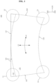
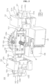
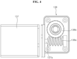
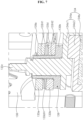
- FIGS. 1 to 52 are diagrams illustrating examples of a display device according to embodiments of the present disclosure.
- OLED Organic Light Emitting Diode
- the display device may include a first long side LS1, a second long side LS2 opposite to the first long side LS1, a first short side SS1 adjacent to one end of each of the first long side LS1 and the second long side LS2, and a second short side SS2 opposite to the first short side SS1.
- an area of the first short side SS1 may be referred to as a first side area
- an area of the second short side SS2 may be referred to as a second side area opposite to the first side area
- an area of the first long side LS1 may be referred to as a third side area adjacent to the first side area and the second side area and disposed between the first side area and the second side area
- an area of the second long side LS2 may be referred to as a fourth side area adjacent to the first side area and the second side area, disposed between the first side area and the second side area, and opposite to the third side area.
- first and second long sides LS1 and LS2 are longer than the first and second short sides SS1 and SS2, but it is also possible that the lengths of the first and second long sides LS1 and LS2 may be approximately equal to the lengths of the first and second short sides SS1 and SS2.
- a first direction DR1 may be a direction parallel to the long sides LS1 and LS2 of the display device
- a second direction DR2 may be a direction parallel to the short sides SS1 and SS2 of the display device.
- a third direction DR3 may be a direction perpendicular to the first direction DR1 and/or the second direction DR2.
- the first direction DR1 and the second direction DR2 may be collectively referred to as a horizontal direction. Further, the third direction DR3 may be referred to as a vertical direction.
- a side or a surface, on which the display device displays an image may be referred to as a front side or a front surface.
- a side or a surface, at which the image cannot be observed may be referred to as a rear side or a rear surface.
- the first long side LS1 may be referred to as an upper side or an upper surface
- the second long side LS2 may be referred to as a lower side or a lower surface.
- the first short side SS1 may be referred to as a left side or a left surface
- the second short side SS2 may be referred to as a right side or a right surface.
- the first long side LS1, the second long side LS2, the first short side SS1, and the second short side SS2 may be referred to as edges of the display device. Further, positions where the first long side LS1, the second long side LS2, the first short side SS1, and the second short side SS2 meet each other may be referred to as corners.
- a position where the first long side LS1 and the first short side SS1 meet each other may be referred to as a first corner C1
- a position where the first long side LS1 and the second short side SS2 meet each other may be referred to as a second corner C2
- a position where the second short side SS2 and the second long side LS2 meet each other may be referred to as a third corner C3
- a position where the second long side LS2 and the first short side SS1 meet each other may be referred to as a fourth corner C4.
- a direction from the first short side SS1 to the second short side SS2 or a direction from the second short side SS2 to the first short side SS1 may be referred to as a left-right direction LR.
- a direction from the first long side LS1 to the second long side LS2 or a direction from the second long side LS2 to the first long side LS1 may be referred to as an up-down direction UD.
- a display panel 110 may be coupled to a plate 120.
- the plate 120 may be flexible.
- the plate 120 may be referred to as a flexible plate 120, a frame 120, or a module cover 120.
- the display panel 110 may be disposed on a front side or a front surface of the plate 120.
- the display panel 110 may be flexible.
- the display panel 110 may be an OLED panel.
- the display panel 110 may be provided on a front surface of a display device 100 and may display an image.
- the display panel 110 may divide an image into a plurality of pixels and may output the image while controlling color, brightness, and chroma of the respective pixels.
- the display panel 110 may generate light corresponding to red, green, or blue color in response to a control signal.
- the display device 100 may have a variable curvature.
- the left and right sides of the display device 100 may move forward.
- the display device 100 may be curved concavely.
- the plate 120 may be curved with the same curvature as the display panel 110.
- the display panel 110 may be curved corresponding to the curvature of the plate 120.
- the plate 120 may be coupled to the rear of the display panel 110.
- the plate 120 may support the display panel 110 at the rear of the display panel 110.
- the plate 120 may have a shape corresponding to the display panel 110.
- a driving module 130 may be coupled to the rear of the plate 120.
- a front bracket 130F, a rear bracket 130R, and wing brackets 131 and 132 may be disposed at the rear of the plate 120.
- the front bracket 130F may be coupled or fixed to a rear surface of the plate 120.
- the rear bracket 130R may be disposed at the rear of the front bracket 130F, may be spaced apart from the front bracket 130F, and may face the front bracket 130F.
- the wing brackets 131 and 132 may include bracket frames 131a and 132a and wing holders 131b and 132b.
- the bracket frames 131a and 132a may be in the shape of a rectangular box.
- the wing holders 131b and 132b may be formed on one side of the bracket frames 131a and 132a.
- the wing holders 131b and 132b may protrude from one surface of the bracket frames 131a and 132a.
- the wing holders 131b and 132b may form a pair.
- the pair of wing holders 131b and 132b may be disposed opposite each other.
- the plurality of wing brackets 131 and 132 may include a first wing bracket 131 and a second wing bracket 132.
- the first wing bracket 131 may be coupled or fixed to the front bracket 130F and/or the rear bracket 130R, and may be opposite the second wing bracket 132 with respect to the front bracket 130F.
- the second wing bracket 132 may also be coupled or fixed to the front bracket 130F and/or the rear bracket 130R.
- Wings 141 and 142 may include blades 141a and 142a, necks 141b and 142b, and levers 141c and 142c.
- the wings 141 and 142 may be made of metal.
- the wings 141 and 142 may be made of an aluminum alloy.
- the blades 141a and 142a may be elongated plates and may include ribs for providing rigidity.
- the levers 141c and 142c and the necks 141b and 142b may be formed at one end of the blades 141a and 142a.
- the necks 141b and 142b disposed between the levers 141c and 142c and the blades 141a and 142a, may connect the levers 141c and 142c and the blades 141a and 142.
- a width of the necks 141b and 142b may be smaller than a width of the levers 141c and 142c, and a width of the levers 141c and 142c may be smaller than a width of the blades 141a and 142a.
- Pivot shafts 141p and 142p may be formed at the necks 141b and 142b.
- the pivot shafts 141p and 142p may be inserted into the wing holders 131b and 132b.
- the wings 141 and 142 may pivot about the pivot shafts 141p and 142p and the wing holders 131b and 132b.
- a first wing 141 may be rotatably or pivotally coupled to the first wing bracket 131, and a second wing 142 may be rotatably or pivotally coupled to the second wing bracket 132.
- the first wing 141 may be symmetric to the second wing 142 with respect to the driving unit 130.
- Sliding mounts 151 and 152 may be coupled or fixed to a rear side or rear surface of the plate 120.
- a first sliding mount 151 may be disposed adjacent to a left side of the plate 120, and a second sliding mount 152 may be disposed adjacent to a right side of the plate 120.
- a distal end of the first wing 141 may be movably coupled to the first sliding mount 151.
- a distal end of the second wing 142 may be movably coupled to the second sliding mount 152.
- a flip frame 133 may be disposed between a lever 141c of the first wing 141 and a lever 142c of the second wing 142, and may be coupled to the levers 141c and 142c.
- the flip frame 133 may be made of metal.
- the flip frame 133 may include a first frame 133a and a second frame 133b.
- the first frame 133a may have a U-shape
- the second frame 133b may have a U-shape.
- the first frame 133a may be pivotally connected to the second frame 133b.
- a pivot pin 133c may pass through the first frame 133a and the second frame 133b to connect the first frame 133a and the second frame 133b.
- the first frame 133a may pivot with respect to the second frame 133b, and the second frame 133b may pivot with respect to the first frame 133a.
- the first frame 133a may be fixed or coupled to the lever 141c of the first wing 141, and the second frame 133b may be fixed or coupled to the lever 142c of the second wing 142.
- a moving block 134 may be disposed inside the flip frame 133.
- the moving block 134 may be disposed between the first frame 133a and the second frame 133b of the flip frame 133.
- a lead screw 135 may be inserted into the moving block 134.
- the moving block 134 may be moved on the lead screw 135 by rotation of the lead screw 135.
- the moving block 134 may make a reciprocal movement along the lead screw 135.
- the lead screw 135 may be coupled to the driving gear 136 and may rotate together with the driving gear 136.
- the driving gear 136 may rotate while facing the rear surface of the plate 120 (see FIG. 2 ).
- the lead screw 135 may be a rotating shaft of the driving gear 136.
- a bearing B may be coupled to one end and/or both ends of the lead screw 135.
- the lead screw 135 may rotate with a first end being inserted into a front bearing B and a second end being inserted into a rear bearing B.
- the lead screw 135 may be press-fit into the front bearing B and the rear bearing B.
- a motor 137 may be disposed under the moving block 134.
- the motor 137 may provide torque.
- a gear box 138 may transmit the torque of the motor 137 to the driving gear 136.
- a first gear 138a may be fixed to a rotating shaft 137a of the motor 137 to rotate together with the rotating shaft 137a of the motor 137.
- the first gear 138a may be a worm.
- a second gear 138b may mesh with the first gear 138a.
- the second gear 138b may be a worm gear.
- the first gear 138a and the second gear 138b may be located inside the gear box 138.
- a transmission gear 138c may be located outside the gear box 138.
- the transmission gear 138c may be fixed to the rotating shaft 137a of the second gear 138b and may rotate together with the second gear 138b.
- the transmission gear 138c may mesh with the driving gear 136.
- the lead screw 135 may be a rotating shaft of the driving gear 136.
- the driving gear 136 may be fixed to the lead screw 135.
- the driving gear 136 may be coupled to the lead screw 135 by a pin.
- the lead screw 135 may include a shaft body 135a and a screw 135b.
- the shaft body 135a may be in the shape of an elongated cylinder, and the screw 135b may be formed on an outer circumferential surface of the shaft body 135a.
- the moving block 134 may include a moving body 134a and a sliding block 134b.
- the moving body 134a may be made of metal
- the sliding block 134b may be made of a synthetic resin.
- the sliding block 134b may be disposed inside the moving body 134a.
- the sliding block 134b may be screwed with the lead screw 135.
- the lead screw 135 may be inserted into the sliding block 134b.
- the sliding block 134b may be moved on the lead screw 135 when the lead screw 135 rotates. Clearance may be formed between an inner circumferential surface of the sliding block 134b and the screw 135b of the lead screw 135, thereby preventing the moving block 135 from being caught or locked while moving on the lead screw 135.
- the moving body 134a may include an outer part 134a1 and an inner part 134a2.
- the outer part 134a1 may form an outer surface of the moving body 134a.
- the inner part 134a2 may be coupled to the inside of the outer part 134a1.
- the outer part 134a1 may be a U-shaped metal plate, and the inner part 134a2 may be a metal shell having an inner receiving space.
- the sliding block 134b may be coupled to the inside of the inner part 134a2.
- a pivot pin 133c may extend by protruding from the outer part 134a1 of the moving body 134a.
- the first frame 133a and the second frame 133b of the flip frame 133 may include holes 133H1 and 133H2.
- the pivot pin 133c may be inserted into the hole 133H2 of the second frame 133b and the hole 133H1 of the first frame 133a.
- a disc 133d may be disposed between the first frame 133a and the second frame 133b, and the pivot pin 133c may be inserted into a hole 133dH of the disk 133d.
- the disk 133d may be made of a material having high durability and low friction characteristics.
- An intermediate member 139 may be disposed between the moving body 134a, the pivot pin 133c, and the flip frame 133.
- the intermediate member 139 may cover an upper surface of the moving body 134a and an outer surface of the pivot pin 133c.
- the intermediate member 139 may be referred to as a low friction member 139 or a lubricating member 139.
- the intermediate member 139 may be referred to as a skin member 139.
- the intermediate member 139 may include a body part 139a and a flange part 139b.
- the body part 139a may have a cylindrical shape.
- the pivot pin 133c may be inserted into the body part 139a.
- the body part 139a may contact the outer surface of the pivot pin 133c, and the flange part 139b may contact the upper surface of the moving body 134a.
- the intermediate member 139 may be made of a synthetic resin having low friction characteristics.
- the intermediate member 139 may be made of a low friction material.
- the intermediate member 139 may be made of polyoxymethylene (POM, acetal homopolymer).
- POM polyoxymethylene
- the first frame 133a and the second frame 133b of the flip frame 133 may move about the pivot pin 133c while making contact with or rubbing against the intermediate member 139.
- the intermediate member 139 may fill a gap between the hole 133H1 of the first frame 133a of the flip frame 133 and the pivot pin 133c.
- the intermediate member 139 may fill a gap between the hole 133H2 of the second frame 133b of the flip frame 133 and the pivot pin 133c.
- the second frame 133b of the flip frame 133 may be placed on the intermediate member 139. Accordingly, the pivot pin 133c may transmit force to the flip frame 133 without causing noise or vibrations.
- the moving block 134 and the flip frame 133 may move on the lead screw 135.
- the flip frame 133 may make a reciprocal movement in a longitudinal direction of the lead screw 135. The movement of the flip frame 133 allows the first wing 141 and/or the second wing 142 to pivot about the pivot shafts 141P and 142P.
- the first distance D1 increases such that less force is required to drive the wings 141 and 142, thereby increasing power transmission efficiency of the driving unit 130 and reducing power consumption of the motor 137.
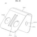
- an elastic member 101 may include a first part 101a, a second part 101b, and a third part 101c.
- the elastic member 101 may be referred to as a first elastic member 101 or a clip 101.
- the first part 101a may be a plate.
- the second part 101b may be bent and extend from the first part 101a.
- the third part 101c may be bent and extend from the second part 101b.
- the third part 101c may face the first part 101a.
- a second angle formed between the second part 101b and the third part 101c may be greater than a first angle formed between the first part 101a and the second part 101b. In the extending direction, the third part 101c may be longer than the first part 101a.
- the elastic member 101 may be a metal plate and may have elasticity.
- the elastic member 101 may be a leaf spring.
- the elastic member 101 may be inserted between the moving block 134 and the levers 141c and 142c of the wings 141 and 142.
- the first part 101a of the elastic member 101 may be fixed to the levers 141c and 142c of the wings 141 and 142.
- the first part 101a of the elastic member 101 may be screw-coupled to the levers 141c and 142c of the wings 141 and 142.
- the third part 101c of the elastic member 101 may support the moving block 134.
- the third part 101c of the elastic member 101 may contact a side surface of the moving block 134.
- the third part 101c of the elastic member 101 may contact the outer part 134a1 and/or the inner part 134a2 of the moving body 134a.
- Each of the plurality of elastic members 101 may be inserted between the moving block 134 and the lever 141c of the first wing 141 and between the moving block 134 and the lever 142c of the second wing 142.
- clearance may be formed between the pivot pin 133c of the moving block 134 and the holes 133H1 and 133H2 (see FIG. 7 ) of the flip frame 133.
- the elastic member 101 may push the moving block 134 in one direction.
- the pivot pin 133 c of the moving block 134 may be pressed against one side of the holes 133H1 and 133H2 of the flip frame 133.
- the moving block 134 may transmit force to the flip frame 133.
- the clearance between the components may cause the display panel 110 to temporarily stop bending.
- the display panel 110 may be bent continuously.
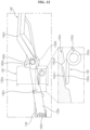
- an elastic member 102 may include a lever part 102a, support parts 102d and 102e, and coil parts 102b and 102c.
- the elastic member 102 may be formed as a wire.
- the elastic member 102 may be referred to as a second elastic member 102.
- the lever part 102a may be a wire bent in a U-shape.
- the coil parts 102b and 102c may be connected to the lever part 102a.
- a first coil part 102b may be connected to a first end of the lever part 102a, and the second coil part 102c may be connected to a second end of the lever part 102a.
- a first support part 102d may form a distal end of the first coil part 102b, and the second support part 102e may form a distal end of the second coil part 102c.
- the lever part 102a When the support parts 102d and 102e are fixed, the lever part 102a may rotate or pivot about the coil parts 102b and 102c.
- the coil parts 102b and 102c may provide elasticity to the lever part 102a.
- the elastic member 102 may be disposed on the wing bracket 132.
- the support parts 102d and 102e of the elastic member 102 may be fixed to the bracket frame 132a of the wing bracket 132.
- the lever part 102a of the elastic member 102 may be supported by the lever 142c of the wing 142.
- the wing 142 may include a support groove 142c2 and a friction pad 142c1.
- the support groove 142c2 may be formed at a position corresponding to a portion of a length of the lever part 102a of the elastic member 102.
- the friction pad 142c1 may be formed on the support groove 142c2.
- the friction pad 142c1 may protrude from the support groove 142c2 and a surface of the friction pad 142c1 may be smoothly polished.
- clearance may be formed between the pivot shafts 141p and 142p of the wings 141 and 142 and the wing holders 131b and 132b of the wing brackets 131 and 132.
- the clearance may cause the display panel 110 to temporarily stop bending.
- the wings 141 and 142 may receive force from the elastic member 102 in a forward direction of the display device 100. Accordingly, the display panel 110 may be bent continuously. In addition, power consumption of the motor 137 required to bend the display panel 110 may be reduced.
- the sliding block 134b (see FIG. 6 ) is screwed with the lead screw 135, clearance may be formed for the sliding block 134b to move on the lead screw 135.
- the display panel 110 may be bent continuously.
- flatness of the display panel 110 may be changed. In this embodiment, the display panel 110 may remain flat and/or curved with a predetermined curvature.
- clearance may be formed between the pivot shafts 141p and 142p of the wings 141 and 142 and the wing holders 131b and 132b of the wing brackets 131 and 132.
- the clearance between the components may cause the display panel 110 to temporarily stop bending.
- Elastic rings 103 and 104 may be disposed around the outer circumference of the lead screw 135.
- the lead screw 135 may be inserted into the elastic rings 103 and 104.
- the elastic rings 103 and 104 may be referred to as compression rings 103 and 104 or compression members 103 and 104.
- the elastic rings 103 and 104 may be highly elastic rubber.
- a diameter of the elastic rings 103 and 104 may be greater than a diameter of the shaft body 135a of the lead screw 135.
- an inner diameter of the elastic rings 103 and 104 may be greater than an outer diameter of the shaft body 135a of the lead screw 135.
- the plurality of elastic rings 103 and 104 may include a first elastic ring 103 and a second elastic ring 104.
- the first elastic ring 103 may be referred to as a front elastic ring 103 and the second elastic ring 104 may be referred to as a rear elastic ring 104.
- the front elastic ring 103 may be disposed between the driving gear 136 and the moving block 136.
- the front elastic ring 103 may contact the driving gear 136.
- the front elastic ring 103 may be brought into contact with or separated from the inner part 134a2 of the moving block 134 when the moving block 134 moves on the lead screw 135. While moving closer to the driving gear 136, the moving block 134 may compress the front elastic ring 103. Further, while moving away from the driving gear 136, the front elastic ring 103 may push the moving block 134.
- the rear elastic ring 104 may be disposed between the bearing B and the moving block 134.
- the rear elastic ring 104 may contact the bearing B.
- the rear elastic ring 104 may be brought into contact with or separated from the outer part 134a1 of the moving block 134 when the moving block 134 moves on the lead screw 135. While moving closer to the bearing B, the moving block 134 may compress the rear elastic ring 104. Further, while moving away from the bearing B, the rear elastic ring 104 may push the moving block 134.
- the display panel 110 may be bent continuously.
- a large amount of power may be consumed during initial driving to bend or flatten the display panel 110.
- the elastic rings 103 and 104 push the moving block 134, thereby reducing the power consumed by the motor 137 to bend the display panel 110.
- the pivot pin 133c may be inserted into the holes 133H1 and 133H2 of the flip frame 133, and the moving block 134 may move on the lead screw 135.
- the display panel 110 changes from flat (see FIG. 17 ) to curved (see FIG. 19 ), in which the display panel 110 may be curved with a constant curvature (see FIG. 19 ).
- a direction in which the pivot pin 133c applies force to the holes 133H1 and 133H2 of the flip frame 133 may be changed.
- clearance formed between the pivot pin 133c and the holes 133H1 and 133H2 of the flip frame 133 may cause a continuous change in curvature of the display panel 110 to stop.
- the major axis of the holes 133H1 and 133H2 may become parallel to a baseline connecting the pivot shafts 141p and 142p of the wings 141 and 142 of the moving block 134.
- the moving direction of the pivot pin 133c may be aligned with a direction of the minor axis of the holes 133H1 and 133H2 of the flip frame 133.
- the pivot pin 133c When the moving direction of the pivot pin 133c is changed such that the moving direction of the pivot pin 133c is aligned with the minor axis of the holes 133H1 and 133H2 of the flip frame 133, clearance formed between the pivot pin 133c and the holes 133H1 and 133H2 of the flip frame 133 may be minimized. Accordingly, by the movement and/or direction change of the moving block 134, the pivot pin 133c may continuously transmit power or force to the flip frame 133.
- the driving module 130 may be disposed between the first sliding mount 151 and the second sliding mount 152 and may be coupled to the rear surface of the plate 120.
- the first wing 141 may have a first end pivotally connected to the driving module 130 and a second end coupled to the first sliding mount 151.
- the second end of the first wing 151 may move on the first sliding mount 151.
- the second wing 142 may have a first end pivotally connected to the driving module 130 and a second end coupled to the second sliding mount 152.
- the second end of the second wing 142 may move on the second sliding mount 152.
- a PCB plate 159 may be disposed at the rear of the driving module 130.
- the PCB plate 159 may be fixed to the rear bracket 130R (see FIG. 2 ) of the driving module 130.
- Printed Circuit Boards PCBs
- PCBs may be coupled to the PCB plate 159.
- a side cover 201 may form a wall around the sides of the driving module 130.
- the side cover 201 may be a square frame.
- a back cover (not shown) may be coupled to the side cover 201 while covering the driving module 130.
- a slide bracket 160 may be coupled or fixed to distal ends of the wings 141 and 142.
- the slide bracket 160 may include a body 161 having an elongated plate shape and protrusions 162 and 163 formed adjacent to both ends of the body 161.
- the protrusions 162 and 163 may be referred to as friction protrusions 162 and 163 or contact protrusions 162 and 163.
- the slide bracket 160 may be made of metal.
- the plurality of protrusions 162 and 163 may include front protrusions 163 and rear protrusions 162.
- the front protrusions 163 may be formed at the first corner C1 and/or the fourth corner C4 of the body 161.
- the front protrusions 163 may protrude by being pressed toward the front of the body 161.
- the front protrusions 163 may have a dome shape or a hemispherical shape.
- the rear protrusions 162 may be formed at the second corner C2 and/or the third corner C3 of the body 161.
- the rear protrusions 162 may protrude by being pressed toward the rear of the body 161.
- the rear protrusions 162 may have a dome shape or a hemispherical shape.
- the rear protrusions 162 may be adjacent to the front protrusions 163.
- the front protrusions 163 and the rear protrusions 162 may be disposed sequentially along the short side of the body 161.
- One pair of the front protrusion 163 and the rear protrusion 162 may be disposed opposite another pair of the front protrusion 163 and the rear protrusion 162 with respect to the wings 141 and 142.
- the slide bracket 160 may be coupled to the guide cover 170.
- the slide bracket 160 may be inserted into the guide cover 170 and may move on the guide cover 170.
- the guide cover 170 may be made of a synthetic resin having low frictional force.
- the guide cover 170 may be made of a low friction material.
- the guide cover 170 may be made of polyoxymethylene (POM, acetal homopolymer).
- the guide cover 170 may include a base 171, a side rail 172, and a fixing plate 173.
- the base 171 may have an elongated plate shape and may face the slide bracket 160.
- the side rail 172 may be formed at both ends of the base 171.
- the side rail 172 may include a lower part 172L and an upper part 172U.
- the lower part 172L may extend from the base 171.
- a lower trench 172LT may be formed in the lower part 172L.
- the lower trench 172LT may be formed in the lower part 172L as an upper surface of the lower part 172L is recessed inward in an elongated shape.
- the lower trench 172LT may be in the shape of a half pipe.
- the front protrusion 163 of the slide bracket 160 may move on the lower trench 172LT.
- a radius of curvature of the front protrusion 163 may be smaller than a radius of curvature of the lower trench 172LT. Accordingly, the front protrusion 163 may make point contact with the lower trench 172LT.
- the upper part 172U may be spaced apart from the lower part 172LT and may face the lower part 172L.
- a gap may be formed between the upper part 172U and the lower part 172L, and the slide bracket 160 may be inserted into the gap.
- An upper trench 172UT may be formed in the upper part 172U.
- the upper trench 172UT may be formed in the upper part 172UT as a lower surface of the upper part 172U is recessed inward in an elongated shape.
- the upper trench 172UT may be in the shape of a half pipe.
- the rear protrusion 162 of the slide bracket 160 may move on the upper trench 172UT.
- a radius of curvature of the rear protrusion 162 may be smaller than a radius of curvature of the upper trench 172UT. Accordingly, the rear protrusion 162 may make point contact with the upper trench 172UT.
- the slide bracket 160 may include a coupling part 161a and a PEM nut 161b or a coupling protrusion 161b for coupling with the wings 141 and 142.
- the guide cover 170 may include a PEM nut 170b or a coupling protrusion 170b for coupling with the sliding mounts 151 and 152.
- the slide bracket 160 may be coupled to front surfaces of the wing blades 141a and 142b at a position adjacent to the distal ends of the wings 141 and 142.
- the guide cover 170 may be fixed to the sliding mounts 151 and 152.
- the slide bracket 160 may be inserted into the guide cover 170 and may make a reciprocal movement on the guide cover 170 in a longitudinal direction of the wings 141 and 142.
- the slide bracket 160 may move on the guide cover 170 toward the short sides SS1 and SS2 of the plate 120.
- the front protrusion 163 may move on the lower trench 172LT.
- the front protrusion 163 may move on the lower trench 172LT while making contact with or rubbing smoothly against a surface of the lower trench 172LT.
- the rear protrusion 162 may move on the upper trench 172UT while making contact with or rubbing smoothly against a surface of the upper trench 172UT.
- the slide bracket 160 may move on the guide cover 170 from the short sides SS1 and SS2 of the plate 120 toward the driving module 130.
- the front protrusion 163 may move on the lower trench 172LT.
- the front protrusion 163 may move on the lower trench 172LT while making contact with or rubbing smoothly against the surface of the lower trench 172LT.
- the rear protrusion 162 may move on the upper trench 172UT while making contact with or rubbing smoothly against the surface of the upper trench 172UT.
- the lower trench 172LT may include a first inclined surface 172a and a second inclined surface 172b
- the upper trench 172UT may include a third inclined surface 172c and a fourth inclined surface 172d.
- the first inclined surface 172a may form a first angle ⁇ 1 with respect to a base surface LB.
- the second inclined surface 172b may form a second angle ⁇ 2 with respect to the base surface LB.
- the second inclined surface 172b may contact the first inclined surface 172a.
- the third inclined surface 172c may form a third angle ⁇ 3 with respect to the base surface UB.
- the fourth inclined surface 172d may form a fourth angle ⁇ 4 with respect to the base UB.
- the fourth inclined surface 172d may be in contact with the third inclined surface 172c.
- a boundary between the third inclined surface 172c and the fourth inclined surface 172d may correspond to or may be aligned with a boundary between the first inclined surface 172a and the second inclined surface 172b.
- the boundary between the third inclined surface 172c and the fourth inclined surface 172d may be vertically aligned on the same line as the boundary between the first inclined surface 172a and the second inclined surface 172b.
- the second angle ⁇ 2 may be greater than the first angle ⁇ 1.
- the third angle ⁇ 3 may be greater than the fourth angle ⁇ 4.
- the first inclined surface 172a may be longer than the second inclined surface 172b.
- the fourth inclined surface 172d may be longer than the third inclined surface 172c.
- the third inclined surface 172c may face the first inclined surface 172a, and the second inclined surface 172b may face the fourth inclined surface 172d.
- the slide bracket 160 to which the wing 140 is coupled, may be inserted into or coupled to the guide cover 170 and the sliding mounts 151 and 152. As the wings 151 and 152 move by pivoting about the driving module 130, the slide bracket 160 may move on the guide cover 170 in a longitudinal direction of the wing 140.
- the slide bracket 160 may move from the first inclined surface 172a to the second inclined surface 172b.
- the slide bracket 160 may move from the second inclined surface 172b to the first inclined surface 172a.
- the front protrusion 163 of the slide bracket 160 may slide in contact with the lower trench 172LT.
- the front protrusion 163 may press and rub against the lower trench 172LT.
- the rear protrusion 162 may slide in contact with the upper trench 172UT or may slide while being supported by the upper trench 172UT.
- the front protrusion 163 of the slide bracket 160 may slide in contact with the lower trench 172LT or may slide while being supported by the lower trench 172LT.
- the rear protrusion 162 may slide in contact with the upper trench 172UT or may slide while being supported by the upper trench 172UT.
- the display panel 110 curved with a predetermined curvature may have a constant curvature or a curvature close to the constant curvature.
- the plate 120 (see FIG. 2 ) may be referred to as a bottom cover 120 and 200 or a rear cover 120 and 200.
- the bottom cover 200 may include a main frame 210 and a side bracket 220.
- the main frame 210 may be a hollow rectangular frame.
- the main frame 210 may be made of a synthetic resin.
- the main frame 210 may include a horizontal part 210H and a vertical part 210V.
- the horizontal part 210H may be elongated along the sides LS1, LS2, SS1, and SS2 of the display panel 110 in a plane direction of the display panel 110 (see FIG. 1 ).
- the vertical part 210V may extend in a direction intersecting an extending direction of the horizontal part 210H and may be formed at an edge of the horizontal part 210H.
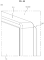
- the main frame 210 may include a first long side part 210LS1, a second long side part 210LS2, a first short side part 210SS1, and a second short side part 210SS2.
- the first long side part 210LS1, the second long side part 210LS2, the first short side part 210SS1, and the second short side part 210SS2 may be integrally formed with each other (see FIG. 44 ).
- the main frame 210 may be flexible in a direction in which the display panel 110 is curved.
- the side bracket 220 may have an elongated plate shape and may be pressed and curved. There may be a plurality of side brackets 220.
- the side bracket 220 may include a flat plate part 221, rib parts 222a, 222b, and 222c, and a support part 223. As the flat plate part 221 is pressed forward, the rib parts 222a, 222b, and 222c may protrude from the flat plate part 221.
- the rib parts 222a, 222b, and 222c may include a first rib 222a, a second rib 222b, and a connection part 222.
- the first rib 222a may be parallel to the second rib 222b, and the connection part 222c may connect the ends of the first rib 222a and the second rib 222b.
- the support part 223 may be pressed rearward from the flat plate part 221 to protrude from the flat plate part 221.
- the support part 223 may be disposed at corners C3 and C4 formed between the short sides SS1 and SS2 and the long sides LS1 and LS2 of the main frame 210.
- the side bracket 220 may be fixed to the main frame 210 by a fastening member f.
- the fastening member f may be a screw.
- a first side bracket 220 may be disposed parallel to the first short side part 210SS1 of the main frame 210, and a second side bracket 220 may be disposed parallel to the second short side part 210SS2 of the main frame 210.
- the side bracket 220 may be coupled to the main frame 210.
- the first side bracket 220 may be coupled to the first short side part 210SS1
- the second side bracket 220 may be coupled to the second short side part 210SS2, thereby providing rigidity to the main frame 210.
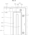
- the bottom cover 200 may include an inner plate 230.
- the inner plate 230 may be coupled to the main frame 210 while covering the main frame 210 and/or the side bracket 220.
- the inner plate 230 may be fixed to the adhesive members AD.
- the inner plate 230 may include a flat plate part 231, side parts 232 and 233, and a receiving part 234.
- the inner plate 230 may include metal and may be a thin plate.
- Cable holes SH1 and SH2 may be formed in the receiving part 234.
- the cable holes SH1 and SH2 may be formed by passing through the receiving part 234.
- a first cable hole SH1 may extend over a first distance D1 on the left side of the inner plate 231.
- the second cable hole SH2 may extend over a first distance D1 on the right side of the inner plate 230.
- the plurality of holes H3 and H4 may be formed in the boundary part at which the steps are formed between the flat plate part 231 and the receiving part 234.
- the plurality of holes H3 and H4 may be long holes or may have an elliptical shape.
- a major axis of the holes H3 and H4 may be vertically aligned.
- the number of the holes H3 and H4 formed in the boundary part may be smaller than the number of the holes H1 and H2 formed in the flat plate part 231.
- the first distance D1 from a center line CL of the inner plate 230 to a first outermost column C1 of the plurality of holes H1 and H2 may be smaller than a second distance D2 from the first short side SS1 and/or the second short side SS2 of the inner plate 230 to a second outermost column C2 of the plurality of holes H1 and H2.
- a first adhesive member AD1 may be fixed to a central region of the inner plate 230.
- the first adhesive member AD1 may be elongated horizontally to be fixed to the central region of the inner plate 230.
- a plurality of first adhesive members AD1 may be vertically spaced apart from each other to be adhered to the inner plate 230.
- the first adhesive member AD1 may be single-sided tape.
- the central region of the inner plate 230 and the first adhesive member AD1 may support the center of the display panel 110 (see FIG. 2 ). As the display panel 110 is curved, the display panel 110 may be curved with a curvature that is symmetrical with respect to the center of the display panel 110.
- a second adhesive member AD2 may be disposed between the first adhesive member AD1 and the second short side SS2 of the inner plate 230.
- the second adhesive member AD2 may be elongated vertically to be fixed to the inner plate 230.
- a plurality of second adhesive members AD2 may be horizontally spaced apart from each other to be adhered to the inner plate 230.
- the second adhesive member AD2 may be double-sided tape. As the display panel 110 is curved, the display panel 110 fixed to the second adhesive member AD2 may slip relative to the inner plate 230, and the second adhesive member AD2 may be deformed in the horizontal direction in response to the relative slip occurring between the display panel 110 and the inner plate 230.
- a third adhesive member AD3 may be disposed between the first adhesive member AD1 and the first short side SS1 of the inner plate 230.
- the third adhesive member AD3 may be elongated vertically to be fixed to the inner plate 230.
- a plurality of third adhesive members AD3 may be horizontally spaced apart from each other to be adhered to the inner plate 230.
- the third adhesive member AD3 may be double-sided tape.
- the display panel 110 fixed to the third adhesive member AD3 may slip relative to the inner plate 230, and the third adhesive member AD3 may be deformed in the horizontal direction in response to the relative slip occurring between the display panel 110 and the inner plate 230.
- a length, width, and position of the third adhesive member AD3 may be symmetric to the second adhesive member AD2 with respect to the first adhesive member AD1. Accordingly, the display panel 110 may be curved symmetrically.
- a fourth adhesive member AD4 may be disposed along the first long side LS1 of the inner plate 230. There may be a plurality of fourth adhesive members AD4, and the plurality of fourth adhesive members AD4 may form a short segment.
- the plurality of fourth adhesive members AD4 are sequentially arranged along the first long side LS1 of the inner plate 230 and may be spaced apart from each other.
- the fourth adhesive member AD4 may be double-sided tape. Accordingly, as the display panel 110 is curved, the fourth adhesive member AD4 may respond to the slip occurring between the display panel 110 and the inner plate 230 and may improve coupling between the display panel 110 and the inner plate 230.
- a fifth adhesive member AD5 may be disposed along the second long side LS2 of the inner plate 230.
- the fifth adhesive member AD5 may be disposed between the coupling parts 211 of the main frame 210 and may be fixed to the receiving part 234 of the inner plate 230.
- the fifth adhesive member AD5 may be longer than the fourth adhesive member AD4.
- the fifth adhesive member AD5 may be double-sided tape.
- a sixth adhesive member AD6 may be elongated to be fixed to the inner plate 230 at a position parallel to and adjacent to the second short side SS2 of the inner plate 230.
- a seventh adhesive member AD7 may be elongated to be fixed to the inner plate 230 at a position parallel to and adjacent to the first short side SS1 of the inner plate 230.
- the sixth adhesive member AD6 and/or the seventh adhesive member AD7 may be double-sided tape.
- An insulation sheet IS may be fixed to the receiving part 234 of the inner plate 230.
- the insulation sheet IS may be elongated along the second long side LS2 of the inner plate 230, and may be disposed parallel to the second long side LS2 of the inner plate 230 at a position adjacent to the coupling part 211 of the main frame 210 (see FIG. 30 ).
- a source PCB of the display panel 110 may be disposed in the receiving part 234, and the insulation sheet IS may prevent electrical short circuit between the inner plate 230, including metal, and the source PCB.
- a gasket AL may be fixed to the inner plate 230.
- the gasket AL may include aluminum.
- the gasket AL may be elongated and may be disposed in the receiving part 234.
- the receiving part 234 may form a plurality of steps with respect to the flat plate part 231.
- the receiving part 234 may include a first receiving part 234b which is stepped downward from the flat plate part 231, and a second receiving part 234a which is stepped downward from the first receiving part 234b.
- the gasket AL may be disposed in the first receiving part 234b.
- a buffering member RB may be fixed to a rear surface of the inner plate 230.
- the buffering member RB may be referred to as an insulation member RB.
- the buffering member RB may be adhered to a rear surface of the flat plate part 231 and/or a rear surface of the receiving part 234.
- the buffering member RB may be rubber and may be adhered to the rear surface of the flat plate part 231 and a rear surface of the first receiving part 234.
- the buffering member RB may be insulation tape.
- An eighth adhesive member AD8 and/or a ninth adhesive member AD9 may be fixed to a rear surface of the side bracket 220.
- the eighth adhesive member AD8 may be elongated and disposed parallel to the second short side SS2 of the main frame 210.
- the ninth adhesive member AD9 may be elongated and disposed parallel to the first short side SS1 of the main frame 210.
- Tenth adhesive members AD10 may include a plurality of segments and may be sequentially arranged along the first long side LS1 of the main frame 210.
- An eleventh adhesive member AD11 may be fixed to the rear surface of the receiving part 234 at a position adjacent to the second long side LS2 of the main frame 210.
- a twelfth adhesive member AD12 and/or a thirteenth adhesive member AD13 may be fixed to a rear surface of the support part 223 of the side bracket 220.
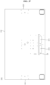
- the bottom cover 200 may include an outer plate 240.
- the outer plate 240 disposed at the rear of the inner plate 230 may be fixed to the main frame 210 and/or the rear surface of the side bracket 220.
- the outer plate 240 may be a flexible thin metal plate.
- the outer plate 240 may be a flexible thin plastic plate.
- the outer plate 240 may include the cable holes SH1 and SH2.
- the cable holes SH1 and SH2 may include a first cable hole SH1 and a second cable hole SH2.
- the first cable hole SH1 of the outer plate 240 may correspond to the second cable hole SH2 of the inner plate 230, and the second cable hole SH2 of the outer plate 240 may correspond to the first cable hole SH1 of the inner plate 220.
- the insulation sheet IS may be fixed to a front surface of the outer plate 240 at a position adjacent to the cable holes SH1 and SH2.
- the insulation sheet IS may be adhered to the front surface of the outer plate 240 while covering edges of the cable holes SH1 and SH2.
- the bottom cover 200 may include a rear plate 250.
- the rear plate 250 may be referred to as a center plate 250.
- the rear plate 250 may be coupled between the inner plate 230 and the outer plate 240.
- the rear plate 250 may be fixed to the front surface of the outer plate 240 by an adhesive member AD (not shown).
- the rear plate 250 may be fixed to the rear surface of the inner plate 230 by the adhesive member AD.
- a size of the rear plate 250 may be smaller than a size of the outer plate 240.
- the rear plate 250 may be a thin metal plate.
- a thickness of the rear plate 250 may be smaller than a thickness of the outer plate 240.
- the outer plate 240 may have a thickness of 0.5 mm
- the rear plate 250 may have a thickness of 0.4 mm.
- the rear plate 250 may reinforce the bending rigidity of a center portion of the bottom cover 200.
- a length L of the rear plate 250 may be equal to or slightly smaller than a length of the first short side SS1 and/or a length of the second short side SS2.
- a width W of the rear plate 250 may be smaller than a length of the first long side LS1 and/or a length of the second long side LS2 of the outer plate 240.
- a first distance W1 from the first short side SS1 of the outer plate 240 to the rear plate 250 may be equal to a second distance W2 from the second short side SS2 of the outer plate 240 to the rear plate 250.
- the width W of the rear plate 250 may be greater than the first distance W1 and/or the second distance W2.
- the rear plate 250 may have cable holes SH1 and SH2.
- the cable holes SH1 and SH2 of the rear plate 250 may correspond to the cable holes SH1 and SH2 of the inner plate 230 and the outer plate 240.
- a twentieth adhesive member AD20 may be elongated in an up-down direction of the rear plate 250. There may be a plurality of twentieth adhesive members AD20 which may be spaced apart from each other in a left-right direction of the rear plate 250.
- a twenty-first adhesive member AD21 may be elongated along an upper side of the rear plate 250 and may be fixed to a front surface of the rear plate 250.
- a plurality of twenty-second adhesive members AD22 may be provided and may be short segments.
- the twenty-second adhesive members AD22 may be sequentially arranged along the upper side of the rear plate 250.
- the twenty-second adhesive members AD22 may be spaced apart from each other.
- a twenty-third adhesive member AD23 may be sequentially arranged along a lower side of the rear plate 250 and may be fixed to the front surface of the rear plate 250.
- a plurality of twenty-third adhesive members AD23 may be provided and may be spaced apart from each other.
- the twenty-third adhesive members AD23 may be formed as short segments.
- the inner plate 230 may be axisymmetric with respect to a center line CL, a configuration of the left side of the inner plate 230 will be described below while a description of the right side, which is symmetrical to the left side, may be omitted (see FIGS. 40 and 41 ).
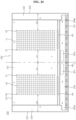
- a plurality of holes H may be formed in the flat plate part 231 of the inner plate 230.
- a plurality of slits SL may be formed in the flat plate part 231 of the inner plate 230 and/or the side parts 232 and 233.
- the plurality of slits SL may include long slits SL1 and SL3 and short slits SL2 and SL4.
- the plurality of holes H may be spaced apart by a first distance D1 from the center line CL of the inner plate 230.
- the plurality of holes H may be formed in the flat plate part 231 while forming rows and columns.
- a first plurality of holes H1 may be formed on the right side of the center line CL of the inner plate 230 and may form a rectangular shape which is elongated in an up-down direction of the inner plate 230.
- the first plurality of holes H1 may form 19 rows and 4 columns.
- the holes H1 may be arranged at regular intervals.
- An area in which the first plurality of holes H1 are formed may be referred to as a first area A1.
- a first plurality of long slits SL1 may be formed on the right side of the center line CL of the inner plate 230 and may be elongated horizontally.
- the first plurality of long slits SL1 may be vertically spaced apart from each other at regular intervals.
- a tenth plurality of holes H10 may be formed between the first plurality of long slits SL1.
- the tenth plurality of holes H10 may be sequentially arranged in a longitudinal direction of the first plurality of long slits SL1. Intervals between the tenth plurality of holes H10 may be equal to intervals between the first plurality of holes H1.
- An area in which the first plurality of long slits SL1 are formed may be referred to as a second area A2.
- the tenth plurality of holes H10 may be formed in the second area A2.
- the second area A2 may be adjacent to the first area A1 and may be disposed between the first area A1 and the second short side SS2.
- a length of the second area A2 may be equal to a length of the first area A1.
- a width of the second area A2 may be greater than a width of the first area A1.
- a third area A3 may be disposed between the second area A2 and the second short side SS2.
- the third area A3 may partially overlap the second area A3.
- the first plurality of short slits SL2 may be formed in the third area A3.
- the first plurality of short slits SL2 may be elongated horizontally.
- Each of the first plurality of short slits SL2 may be disposed between each of the first plurality of long slits SL1.
- a step formed at a boundary between the flat plate part 231 and the side part 232 may be formed in the third area A3.
- a step formed at a boundary between the flat plate part 231 and the side part 232 may be disposed outside the second area A2 and inside the third area A3.
- a length of the third area A3 may be equal to a length of the second area A2.
- a width of the third area A3 may be smaller than a width of the second area A2.
- a width of the third area A3 may be smaller than a width of the first area A1.
- a second plurality of holes H2 may be located on the left side of the center line CL of the inner plate 230 and may form a rectangular shape which is elongated in the up-down direction of the inner plate 230.
- the second plurality of holes H2 may form 19 rows and 4 columns.
- the holes H2 may be arranged at regular intervals.
- An area in which the second plurality of holes H2 are formed may be referred to as a fourth area A4.
- a second plurality of long slits SL3 may be formed on the left side of the center line CL of the inner plate 230 and may be elongated horizontally.
- the second plurality of long slits SL3 may be vertically spaced apart from each other at regular intervals.
- a twentieth plurality of holes H20 may be formed between the second plurality of long slits SL3.
- the twentieth plurality of holes H20 may be sequentially arranged in the longitudinal direction of the second plurality of long slits SL3. Intervals between the twentieth plurality of holes H20 may be equal to intervals between the second plurality of holes H2.
- An area in which the second plurality of long slits SL3 are formed may be referred to as a fifth area A5.
- the twentieth plurality of holes H20 may be formed in the fifth area A5.
- the fifth area A5 may be adjacent to the fourth area A4 and may be disposed between the fourth area A4 and the first short side SS1.
- a length of the fifth area A5 may be equal to a length of the fourth area A4.
- a width of the fifth area A5 may be greater than a width of the fourth area A4.
- a sixth area A6 may be disposed between the fifth area A5 and the first short side SS1.
- the sixth area A6 may partially overlap the fifth area A5.
- the second plurality of short slits SL4 may be formed in the sixth area A6.
- the second plurality of short slits SL4 may be elongated horizontally.
- Each of the second plurality of short slits SL4 may be disposed between each of the second plurality of long slits SL3.
- a step formed at a boundary between the flat plate part 231 and the side part 233 may be formed in the sixth area A6.
- a step formed at a boundary between the flat plate part 231 and the side part 233 may be disposed outside the fifth area A5 and inside the sixth area A6.
- a length of the sixth area A6 may be equal to a length of the fifth area A5.
- a width of the sixth area A6 may be smaller than a width of the fifth area A5.
- a width of the sixth area A6 may be smaller than a width of the fourth area A4.
- the fourth holes H4 may be long holes elongated vertically.
- the fourth holes H4 may be formed in the eighth area A8.
- the fourth holes H4 may be formed in a step at a boundary between the flat plate part 231 and the first receiving part 234 b.
- the fourth holes H3 are adjacent to and below the fourth area A4 and may be sequentially spaced apart from each other in a width direction of the fourth area A4.
- the coupling tabs 232a and 232b of the inner plate 230 may be connected to the fastening part 221a of the side bracket 220.
- the fastening member f may be a screw.
- the front fastening part 221a may have a cylindrical shape, and a diameter of the through-hole 210I may be substantially equal to a diameter of the front fastening part 221a, wherein a length of the long hole 232H may be greater than the diameter of the front fastening part 221a, and a width of the long hole 232H may be substantially equal to the diameter of the front fastening part 221a.
- a configuration "A” described in one embodiment of the disclosure and the drawings and a configuration "B” described in another embodiment of the disclosure and the drawings may be combined with each other. Namely, although the combination between the configurations is not directly described, the combination is possible except in the case where it is described that the combination is impossible.
Landscapes
- Engineering & Computer Science (AREA)
- Physics & Mathematics (AREA)
- Theoretical Computer Science (AREA)
- General Physics & Mathematics (AREA)
- Optics & Photonics (AREA)
- Computer Hardware Design (AREA)
- Human Computer Interaction (AREA)
- General Engineering & Computer Science (AREA)
- Devices For Indicating Variable Information By Combining Individual Elements (AREA)
Abstract
Description
- The following description relates to a display device, and more particularly to a display device capable of changing a curvature of a display panel.
- With the development of the information society, there have been growing demands for various types of display devices, and in order to meet these demands, various display devices, such as a liquid crystal display (LCD), an electroluminescent display (ELD), a vacuum fluorescent display (VFD), an organic light emitting diode (OLED) panel, etc., have been studied and used recently.
- Among these display devices, the OLED panel may display images via a self-emitting organic layer deposited on a substrate on which transparent electrodes are formed. The OLED panel is not only thin but also has flexible characteristics. Much research is being conducted on the structural characteristics of a display device having the OLED panel.
- It is an objective of the present disclosure to solve the above and other problems. It is another objective of the present disclosure to provide a structure in which a curvature of a display panel may be freely changed.
- It is yet another objective of the present disclosure to provide a mechanism in which a curvature of a display panel may be freely changed.
- It is still another objective of the present disclosure to provide a structure in which a display panel may be curved with a constant curvature.
- In accordance with an aspect of the present disclosure, the above and other objectives can be accomplished by providing a display device including: a flexible display panel; a bottom cover disposed at a rear of the display panel and coupled to the display panel; a driving module disposed at a rear of the bottom cover and including a moving block that makes a reciprocal movement; a wing bracket fixed to the rear of the bottom cover at a position adjacent to the driving module; and a wing elongated with a first end fixed to the moving block and a second end coupled to the bottom cover, the wing pivotally connected to the wing bracket between the first end and the second end, wherein the bottom cover includes: an inner plate coupled to the display panel; a flexible main frame coupled to sides of the inner plate; an outer plate opposite the display panel with respect to the inner plate; and a side bracket disposed between the inner plate and the outer plate and coupled to the main frame, wherein the main frame is fixed to the side bracket, and the side bracket is coupled to the inner plate in a manner that allows for slip therebetween.
- According to at least one of the embodiments of the present disclosure, a structure may be provided in which a curvature of a display panel may be freely changed.
- According to at least one of the embodiments of the present disclosure, a mechanism may be provided in which a curvature of a display panel may be freely changed.
- According to at least one of the embodiments of the present disclosure, a structure may be provided in which a display panel may be curved with a constant curvature.
- Further scope of applicability of the present disclosure will become apparent from the detailed description given hereinafter. However, it should be understood that the detailed description and specific examples, while indicating preferred embodiments of the present disclosure, are given by illustration only, since various changes and modifications within the spirit and scope of the present disclosure will become apparent to those skilled in the art from this detailed description.
-
FIGS. 1 to 52 are diagrams illustrating examples of a display device according to embodiments of the present disclosure. - Hereinafter, the present disclosure will be described in detail with reference to the accompanying drawings, in which the same reference numerals are used throughout the drawings to designate the same or similar components, and a redundant description thereof will be omitted.
- The suffixes, such as "module" and "unit," for elements used in the following description are given simply in view of the ease of the description, and do not have a distinguishing meaning or role. In addition, it will be noted that a detailed description of known arts will be omitted if it is determined that the detailed description of the known arts can obscure the embodiments of the present disclosure. Further, the accompanying drawings are used to help easily understand various technical features and it should be understood that the embodiments presented herein are not limited by the accompanying drawings. As such, the present disclosure should be construed to extend to any alterations, equivalents and substitutes in addition to those which are particularly set out in the accompanying drawings.
- It will be understood that, although the terms first, second, etc., may be used herein to describe various elements, these elements should not be limited by these terms. These terms are only used to distinguish one element from another.
- It will be understood that when an element is referred to as being "connected" or "coupled" to another element, it can be directly connected or coupled to the other element or intervening elements may be present. In contrast, when an element is referred to as being "directly connected" or "directly coupled" to another element, there are no intervening elements present.
- As used herein, the singular forms are intended to include the plural forms as well, unless the context clearly indicates otherwise.
- It should be understood that the terms "comprise," "include," "have," etc. when used in this specification, specify the presence of stated features, integers, steps, operations, elements, components, or combinations thereof but do not preclude the presence or addition of one or more other features, integers, steps, operations, elements, components, or combinations thereof.
- Hereinafter, a display panel will be described by using an Organic Light Emitting Diode (OLED) as an example, but a display panel applicable to the present disclosure is not limited to the OLED panel.
- In addition, in the following description, the display device may include a first long side LS1, a second long side LS2 opposite to the first long side LS1, a first short side SS1 adjacent to one end of each of the first long side LS1 and the second long side LS2, and a second short side SS2 opposite to the first short side SS1.
- Here, an area of the first short side SS1 may be referred to as a first side area, an area of the second short side SS2 may be referred to as a second side area opposite to the first side area, an area of the first long side LS1 may be referred to as a third side area adjacent to the first side area and the second side area and disposed between the first side area and the second side area, and an area of the second long side LS2 may be referred to as a fourth side area adjacent to the first side area and the second side area, disposed between the first side area and the second side area, and opposite to the third side area.
- For convenience of explanation, it is illustrated and described that the first and second long sides LS1 and LS2 are longer than the first and second short sides SS1 and SS2, but it is also possible that the lengths of the first and second long sides LS1 and LS2 may be approximately equal to the lengths of the first and second short sides SS1 and SS2.
- In the following description, a first direction DR1 may be a direction parallel to the long sides LS1 and LS2 of the display device, and a second direction DR2 may be a direction parallel to the short sides SS1 and SS2 of the display device. A third direction DR3 may be a direction perpendicular to the first direction DR1 and/or the second direction DR2.
- The first direction DR1 and the second direction DR2 may be collectively referred to as a horizontal direction. Further, the third direction DR3 may be referred to as a vertical direction.
- A side or a surface, on which the display device displays an image, may be referred to as a front side or a front surface. When the display device displays an image, a side or a surface, at which the image cannot be observed, may be referred to as a rear side or a rear surface. When the display device is viewed from the front side or the front surface, the first long side LS1 may be referred to as an upper side or an upper surface, and the second long side LS2 may be referred to as a lower side or a lower surface. Likewise, the first short side SS1 may be referred to as a left side or a left surface, and the second short side SS2 may be referred to as a right side or a right surface.
- The first long side LS1, the second long side LS2, the first short side SS1, and the second short side SS2 may be referred to as edges of the display device. Further, positions where the first long side LS1, the second long side LS2, the first short side SS1, and the second short side SS2 meet each other may be referred to as corners. For example, a position where the first long side LS1 and the first short side SS1 meet each other may be referred to as a first corner C1, a position where the first long side LS1 and the second short side SS2 meet each other may be referred to as a second corner C2, a position where the second short side SS2 and the second long side LS2 meet each other may be referred to as a third corner C3, and a position where the second long side LS2 and the first short side SS1 meet each other may be referred to as a fourth corner C4.
- Here, a direction from the first short side SS1 to the second short side SS2 or a direction from the second short side SS2 to the first short side SS1 may be referred to as a left-right direction LR. A direction from the first long side LS1 to the second long side LS2 or a direction from the second long side LS2 to the first long side LS1 may be referred to as an up-down direction UD.
- Referring to
FIG. 1 , adisplay panel 110 may be coupled to aplate 120. Theplate 120 may be flexible. Theplate 120 may be referred to as aflexible plate 120, aframe 120, or amodule cover 120. Thedisplay panel 110 may be disposed on a front side or a front surface of theplate 120. Thedisplay panel 110 may be flexible. For example, thedisplay panel 110 may be an OLED panel. - The
display panel 110 may be provided on a front surface of adisplay device 100 and may display an image. Thedisplay panel 110 may divide an image into a plurality of pixels and may output the image while controlling color, brightness, and chroma of the respective pixels. Thedisplay panel 110 may generate light corresponding to red, green, or blue color in response to a control signal. - The
display device 100 may have a variable curvature. The left and right sides of thedisplay device 100 may move forward. For example, when an image is viewed from the front side of thedisplay device 100, thedisplay device 100 may be curved concavely. In this case, theplate 120 may be curved with the same curvature as thedisplay panel 110. Alternatively, thedisplay panel 110 may be curved corresponding to the curvature of theplate 120. - Referring to
FIGS. 2 to 3 , theplate 120 may be coupled to the rear of thedisplay panel 110. Theplate 120 may support thedisplay panel 110 at the rear of thedisplay panel 110. Theplate 120 may have a shape corresponding to thedisplay panel 110. - A
driving module 130 may be coupled to the rear of theplate 120. Afront bracket 130F, arear bracket 130R, andwing brackets plate 120. Thefront bracket 130F may be coupled or fixed to a rear surface of theplate 120. Therear bracket 130R may be disposed at the rear of thefront bracket 130F, may be spaced apart from thefront bracket 130F, and may face thefront bracket 130F. - The
wing brackets bracket frames wing holders wing holders wing holders wing holders wing holders - There may be a plurality of
wing brackets wing brackets first wing bracket 131 and asecond wing bracket 132. Thefirst wing bracket 131 may be coupled or fixed to thefront bracket 130F and/or therear bracket 130R, and may be opposite thesecond wing bracket 132 with respect to thefront bracket 130F. Thesecond wing bracket 132 may also be coupled or fixed to thefront bracket 130F and/or therear bracket 130R. -
Wings blades necks wings wings blades levers necks blades necks levers blades levers blades necks levers levers blades Pivot shafts necks pivot shafts wing holders wings pivot shafts wing holders - A
first wing 141 may be rotatably or pivotally coupled to thefirst wing bracket 131, and asecond wing 142 may be rotatably or pivotally coupled to thesecond wing bracket 132. Thefirst wing 141 may be symmetric to thesecond wing 142 with respect to thedriving unit 130. - Sliding
mounts plate 120. A first slidingmount 151 may be disposed adjacent to a left side of theplate 120, and a second slidingmount 152 may be disposed adjacent to a right side of theplate 120. A distal end of thefirst wing 141 may be movably coupled to the first slidingmount 151. A distal end of thesecond wing 142 may be movably coupled to the second slidingmount 152. - A
flip frame 133 may be disposed between alever 141c of thefirst wing 141 and alever 142c of thesecond wing 142, and may be coupled to thelevers flip frame 133 may be made of metal. Theflip frame 133 may include afirst frame 133a and asecond frame 133b. For example, thefirst frame 133a may have a U-shape, and thesecond frame 133b may have a U-shape. Thefirst frame 133a may be pivotally connected to thesecond frame 133b. Apivot pin 133c may pass through thefirst frame 133a and thesecond frame 133b to connect thefirst frame 133a and thesecond frame 133b. Thefirst frame 133a may pivot with respect to thesecond frame 133b, and thesecond frame 133b may pivot with respect to thefirst frame 133a. Thefirst frame 133a may be fixed or coupled to thelever 141c of thefirst wing 141, and thesecond frame 133b may be fixed or coupled to thelever 142c of thesecond wing 142. - A moving
block 134 may be disposed inside theflip frame 133. The movingblock 134 may be disposed between thefirst frame 133a and thesecond frame 133b of theflip frame 133. - A
lead screw 135 may be inserted into the movingblock 134. The movingblock 134 may be moved on thelead screw 135 by rotation of thelead screw 135. By rotation and reverse rotation of thelead screw 135, the movingblock 134 may make a reciprocal movement along thelead screw 135. - The
lead screw 135 may be coupled to thedriving gear 136 and may rotate together with thedriving gear 136. Thedriving gear 136 may rotate while facing the rear surface of the plate 120 (seeFIG. 2 ). Thelead screw 135 may be a rotating shaft of thedriving gear 136. A bearing B may be coupled to one end and/or both ends of thelead screw 135. Thelead screw 135 may rotate with a first end being inserted into a front bearing B and a second end being inserted into a rear bearing B. For example, thelead screw 135 may be press-fit into the front bearing B and the rear bearing B. - A
motor 137 may be disposed under the movingblock 134. Themotor 137 may provide torque. Agear box 138 may transmit the torque of themotor 137 to thedriving gear 136. - Referring to
FIGS. 4 and5 , afirst gear 138a may be fixed to arotating shaft 137a of themotor 137 to rotate together with therotating shaft 137a of themotor 137. For example, thefirst gear 138a may be a worm. Asecond gear 138b may mesh with thefirst gear 138a. For example, thesecond gear 138b may be a worm gear. - The
first gear 138a and thesecond gear 138b may be located inside thegear box 138. Atransmission gear 138c may be located outside thegear box 138. Thetransmission gear 138c may be fixed to therotating shaft 137a of thesecond gear 138b and may rotate together with thesecond gear 138b. Thetransmission gear 138c may mesh with thedriving gear 136. - The
lead screw 135 may be a rotating shaft of thedriving gear 136. Thedriving gear 136 may be fixed to thelead screw 135. Thedriving gear 136 may be coupled to thelead screw 135 by a pin. - Referring to
FIG. 6 , thelead screw 135 may include ashaft body 135a and ascrew 135b. Theshaft body 135a may be in the shape of an elongated cylinder, and thescrew 135b may be formed on an outer circumferential surface of theshaft body 135a. The movingblock 134 may include a movingbody 134a and a slidingblock 134b. For example, the movingbody 134a may be made of metal, and the slidingblock 134b may be made of a synthetic resin. The slidingblock 134b may be disposed inside the movingbody 134a. The slidingblock 134b may be screwed with thelead screw 135. - The
lead screw 135 may be inserted into the slidingblock 134b. The slidingblock 134b may be moved on thelead screw 135 when thelead screw 135 rotates. Clearance may be formed between an inner circumferential surface of the slidingblock 134b and thescrew 135b of thelead screw 135, thereby preventing the moving block 135 from being caught or locked while moving on thelead screw 135. - Referring to
FIG. 7 , the movingbody 134a may include an outer part 134a1 and an inner part 134a2. The outer part 134a1 may form an outer surface of the movingbody 134a. The inner part 134a2 may be coupled to the inside of the outer part 134a1. For example, the outer part 134a1 may be a U-shaped metal plate, and the inner part 134a2 may be a metal shell having an inner receiving space. The slidingblock 134b may be coupled to the inside of the inner part 134a2. - A
pivot pin 133c may extend by protruding from the outer part 134a1 of the movingbody 134a. Thefirst frame 133a and thesecond frame 133b of theflip frame 133 may include holes 133H1 and 133H2. Thepivot pin 133c may be inserted into the hole 133H2 of thesecond frame 133b and the hole 133H1 of thefirst frame 133a. Adisc 133d may be disposed between thefirst frame 133a and thesecond frame 133b, and thepivot pin 133c may be inserted into a hole 133dH of thedisk 133d. For example, thedisk 133d may be made of a material having high durability and low friction characteristics. - An
intermediate member 139 may be disposed between the movingbody 134a, thepivot pin 133c, and theflip frame 133. Theintermediate member 139 may cover an upper surface of the movingbody 134a and an outer surface of thepivot pin 133c. Theintermediate member 139 may be referred to as alow friction member 139 or a lubricatingmember 139. In addition, theintermediate member 139 may be referred to as askin member 139. - The
intermediate member 139 may include abody part 139a and aflange part 139b. Thebody part 139a may have a cylindrical shape. Thepivot pin 133c may be inserted into thebody part 139a. Thebody part 139a may contact the outer surface of thepivot pin 133c, and theflange part 139b may contact the upper surface of the movingbody 134a. Theintermediate member 139 may be made of a synthetic resin having low friction characteristics. Theintermediate member 139 may be made of a low friction material. For example, theintermediate member 139 may be made of polyoxymethylene (POM, acetal homopolymer). Thefirst frame 133a and thesecond frame 133b of theflip frame 133 may move about thepivot pin 133c while making contact with or rubbing against theintermediate member 139. - The
intermediate member 139 may fill a gap between the hole 133H1 of thefirst frame 133a of theflip frame 133 and thepivot pin 133c. Theintermediate member 139 may fill a gap between the hole 133H2 of thesecond frame 133b of theflip frame 133 and thepivot pin 133c. Thesecond frame 133b of theflip frame 133 may be placed on theintermediate member 139. Accordingly, thepivot pin 133c may transmit force to theflip frame 133 without causing noise or vibrations. - Referring to
FIGS. 8 and9 , when thelead screw 135 rotates, the movingblock 134 and theflip frame 133 may move on thelead screw 135. Theflip frame 133 may make a reciprocal movement in a longitudinal direction of thelead screw 135. The movement of theflip frame 133 allows thefirst wing 141 and/or thesecond wing 142 to pivot about the pivot shafts 141P and 142P. - A first distance D1 from the
pivot pin 133c to the pivot shafts 141P and 142P may be smaller than a second distance D2 from the pivot shafts 141P and 142P to the slidingmounts levers wings flip frame 133, and theflip frame 133 moves together with thepivot pin 133c during movement of thepivot pin 133c, such that a driving force of the movingblock 134 moving on thelead screw 135 may be transmitted efficiently to thelevers wings flip frame 133. - In addition, as the
levers wings flip frame 133 and move together with theflip frame 133, the first distance D1 increases such that less force is required to drive thewings driving unit 130 and reducing power consumption of themotor 137. - Referring to
FIGS. 10 and11 , anelastic member 101 may include afirst part 101a, asecond part 101b, and athird part 101c. Theelastic member 101 may be referred to as a firstelastic member 101 or aclip 101. Thefirst part 101a may be a plate. Thesecond part 101b may be bent and extend from thefirst part 101a. Thethird part 101c may be bent and extend from thesecond part 101b. Thethird part 101c may face thefirst part 101a. A second angle formed between thesecond part 101b and thethird part 101c may be greater than a first angle formed between thefirst part 101a and thesecond part 101b. In the extending direction, thethird part 101c may be longer than thefirst part 101a. Theelastic member 101 may be a metal plate and may have elasticity. For example, theelastic member 101 may be a leaf spring. - A coupling hole 101H1 may be formed in the
first part 101a. There may be a plurality of coupling holes 101H1. Asupport rib 101R may be formed on thethird part 101c. Thesupport rib 101R may be elongated in the direction in which thethird part 101c extends. There may be a plurality ofsupport ribs 101R. Thesupport ribs 101R may protrude from an outer surface of thethird part 101c. The plurality ofsupport ribs 101R may be parallel to each other. - The
elastic member 101 may be inserted between the movingblock 134 and thelevers wings first part 101a of theelastic member 101 may be fixed to thelevers wings first part 101a of theelastic member 101 may be screw-coupled to thelevers wings third part 101c of theelastic member 101 may support the movingblock 134. Thethird part 101c of theelastic member 101 may contact a side surface of the movingblock 134. Thethird part 101c of theelastic member 101 may contact the outer part 134a1 and/or the inner part 134a2 of the movingbody 134a. The outer part 134a1 and/or the inner part 134a2 of the movingbody 134a, making contact with thethird part 101c of theelastic member 101, may be rounded. Thesupport ribs 101R formed on thethird part 101c of theelastic member 101 may contact the inner part 134a2 of the movingblock 134. - There may be a plurality of
elastic members 101. Each of the plurality ofelastic members 101 may be inserted between the movingblock 134 and thelever 141c of thefirst wing 141 and between the movingblock 134 and thelever 142c of thesecond wing 142. - In a mechanism in which the
flip frame 133 flips or pivots about thepivot pin 133c, clearance may be formed between thepivot pin 133c of the movingblock 134 and the holes 133H1 and 133H2 (seeFIG. 7 ) of theflip frame 133. Theelastic member 101 may push the movingblock 134 in one direction. As theelastic member 101 pushes the movingblock 134 in one direction, thepivot pin 133 c of the movingblock 134 may be pressed against one side of the holes 133H1 and 133H2 of theflip frame 133. - Accordingly, in the entire region in which the moving
block 134 moves on thelead screw 134, the movingblock 134 may transmit force to theflip frame 133. In a mechanism in which the movingblock 134 transmits force to theflip frame 133, the clearance between the components may cause thedisplay panel 110 to temporarily stop bending. According to the embodiment of the present disclosure, thedisplay panel 110 may be bent continuously. - Referring to
FIGS. 12 and13 , anelastic member 102 may include alever part 102a,support parts coil parts elastic member 102 may be formed as a wire. Theelastic member 102 may be referred to as a secondelastic member 102. - The
lever part 102a may be a wire bent in a U-shape. Thecoil parts lever part 102a. There may be a plurality ofcoil parts first coil part 102b may be connected to a first end of thelever part 102a, and thesecond coil part 102c may be connected to a second end of thelever part 102a. There may be a plurality ofsupport parts first support part 102d may form a distal end of thefirst coil part 102b, and thesecond support part 102e may form a distal end of thesecond coil part 102c. - When the
support parts lever part 102a may rotate or pivot about thecoil parts coil parts lever part 102a. - The
elastic member 102 may be disposed on thewing bracket 132. Thesupport parts elastic member 102 may be fixed to thebracket frame 132a of thewing bracket 132. Thelever part 102a of theelastic member 102 may be supported by thelever 142c of thewing 142. - The
wing 142 may include a support groove 142c2 and a friction pad 142c1. The support groove 142c2 may be formed at a position corresponding to a portion of a length of thelever part 102a of theelastic member 102. The friction pad 142c1 may be formed on the support groove 142c2. The friction pad 142c1 may protrude from the support groove 142c2 and a surface of the friction pad 142c1 may be smoothly polished. - When the
wings wing brackets pivot shafts wings wing holders wing brackets block 134 transmits force to theflip frame 133 to allow thewings display panel 110, the clearance may cause thedisplay panel 110 to temporarily stop bending. Thewings elastic member 102 in a forward direction of thedisplay device 100. Accordingly, thedisplay panel 110 may be bent continuously. In addition, power consumption of themotor 137 required to bend thedisplay panel 110 may be reduced. - In addition, as the sliding
block 134b (seeFIG. 6 ) is screwed with thelead screw 135, clearance may be formed for the slidingblock 134b to move on thelead screw 135. As theelastic member 102 pushes thewings block 134b in one direction of thelead screw 135, thedisplay panel 110 may be bent continuously. Further, when the torque of themotor 137 and thelead screw 135 is released while thedisplay panel 110 is in a flat shape, flatness of thedisplay panel 110 may be changed. In this embodiment, thedisplay panel 110 may remain flat and/or curved with a predetermined curvature. - Referring to
FIGS. 14 and15 along withFIG. 8 , when thewings wing brackets pivot shafts wings wing holders wing brackets block 134 transmits force to theflip frame 133 to allow thewings display panel 110, the clearance between the components may cause thedisplay panel 110 to temporarily stop bending. - Elastic rings 103 and 104 may be disposed around the outer circumference of the
lead screw 135. Thelead screw 135 may be inserted into theelastic rings 103 and 104. Theelastic rings 103 and 104 may be referred to as compression rings 103 and 104 orcompression members 103 and 104. For example, theelastic rings 103 and 104 may be highly elastic rubber. A diameter of theelastic rings 103 and 104 may be greater than a diameter of theshaft body 135a of thelead screw 135. For example, an inner diameter of theelastic rings 103 and 104 may be greater than an outer diameter of theshaft body 135a of thelead screw 135. There may be a plurality ofelastic rings 103 and 104. The plurality ofelastic rings 103 and 104 may include a firstelastic ring 103 and a second elastic ring 104. The firstelastic ring 103 may be referred to as a frontelastic ring 103 and the second elastic ring 104 may be referred to as a rear elastic ring 104. - The front
elastic ring 103 may be disposed between the drivinggear 136 and the movingblock 136. The frontelastic ring 103 may contact thedriving gear 136. The frontelastic ring 103 may be brought into contact with or separated from the inner part 134a2 of the movingblock 134 when the movingblock 134 moves on thelead screw 135. While moving closer to thedriving gear 136, the movingblock 134 may compress the frontelastic ring 103. Further, while moving away from thedriving gear 136, the frontelastic ring 103 may push the movingblock 134. - The rear elastic ring 104 may be disposed between the bearing B and the moving
block 134. The rear elastic ring 104 may contact the bearing B. The rear elastic ring 104 may be brought into contact with or separated from the outer part 134a1 of the movingblock 134 when the movingblock 134 moves on thelead screw 135. While moving closer to the bearing B, the movingblock 134 may compress the rear elastic ring 104. Further, while moving away from the bearing B, the rear elastic ring 104 may push the movingblock 134. - Accordingly, the
display panel 110 may be bent continuously. In addition, a large amount of power may be consumed during initial driving to bend or flatten thedisplay panel 110. During the initial driving of the movingblock 134, theelastic rings 103 and 104 push the movingblock 134, thereby reducing the power consumed by themotor 137 to bend thedisplay panel 110. - In addition, as the sliding
block 134b (seeFIG. 6 ) is screwed with thelead screw 135, clearance may be formed for the slidingblock 134b to move on thelead screw 135. As the movingblock 134 compresses theelastic rings 103 and 104 or as theelastic rings 103 and 104 push the movingblock 134, the slidingblock 134b may come into close contact with thelead screw 135 in a longitudinal direction of thelead screw 135, such that thedisplay panel 110 may be bent continuously. - In addition, when the torque of the
motor 137 and thelead screw 135 is released while thedisplay panel 110 is in a flat shape, flatness of thedisplay panel 110 may be changed. In this embodiment, thedisplay panel 110 may remain flat and/or curved with a predetermined curvature. - Referring to
FIG. 16 , theflip frame 133 may have the holes 133H1 and 133H2. The holes 133H1 and 133H2 may be formed adjacent to a distal end of thefirst frame 133a and/or thesecond frame 133b of theflip frame 133. The holes 133H1 and 133H2 may be long holes 133H1 and 133H2 having a major axis and a minor axis. The major axis of the holes 133H1 and 133H2 may be parallel to a longitudinal direction of theframe 133. The minor axis of the holes 133H1 and 133H2 may cross the longitudinal direction of theframe 133. - Referring to
FIGS. 17 to 19 , thepivot pin 133c may be inserted into the holes 133H1 and 133H2 of theflip frame 133, and the movingblock 134 may move on thelead screw 135. As the movingblock 134 moves on thelead screw 135, thedisplay panel 110 changes from flat (seeFIG. 17 ) to curved (seeFIG. 19 ), in which thedisplay panel 110 may be curved with a constant curvature (seeFIG. 19 ). - When the
display panel 110 starts to be curved after being in a flat shape, or when the display panel, after being curved with a predetermined curvature, changes to a flat shape as a radius of curvature becomes greater than a predetermined radius of curvature, a moving direction of the movingblock 134 may be changed. That is, at a start point and an end point of the movingblock 134, thedisplay panel 110 may be flat or may be curved with a predetermined curvature. - When the moving direction of the moving
block 134 is changed at the start point and/or the end point, a direction in which thepivot pin 133c applies force to the holes 133H1 and 133H2 of theflip frame 133 may be changed. As the direction in which thepivot pin 133c applies force to the holes 133H1 and 133H2 of theflip frame 133 is changed, clearance formed between thepivot pin 133c and the holes 133H1 and 133H2 of theflip frame 133 may cause a continuous change in curvature of thedisplay panel 110 to stop. - Referring to
FIGS. 20 and21 , the major axis of the holes 133H1 and 133H2 of theflip frame 133 may form an angle θ with respect to a longitudinal direction of theflip frame 133. For example, the angle θ may correspond to an angle θ formed between thepivot shafts wings 141 and 142 (seeFIG. 8 ) and the start point or the end point of the movingblock 134 with respect to a line connecting thepivot shafts wings - As the holes 133H1 and 133H2 of the
flip frame 133 are moved closer to the start point or the end point of the movingblock 134, the major axis of the holes 133H1 and 133H2 may become parallel to a baseline connecting thepivot shafts wings block 134. When a moving direction of thepivot pin 133c is changed, the moving direction of thepivot pin 133c may be aligned with a direction of the minor axis of the holes 133H1 and 133H2 of theflip frame 133. - When the moving direction of the
pivot pin 133c is changed such that the moving direction of thepivot pin 133c is aligned with the minor axis of the holes 133H1 and 133H2 of theflip frame 133, clearance formed between thepivot pin 133c and the holes 133H1 and 133H2 of theflip frame 133 may be minimized. Accordingly, by the movement and/or direction change of the movingblock 134, thepivot pin 133c may continuously transmit power or force to theflip frame 133. - Referring to
FIGS. 22 and23 , a first slidingmount 151 may be fixed to the rear surface of theplate 120 at a position adjacent to the first short side SS1 of theplate 120. The second slidingmount 152 may be fixed to the rear surface of theplate 120 at a position adjacent to the second short side SS2 of theplate 120. - The
driving module 130 may be disposed between the first slidingmount 151 and the second slidingmount 152 and may be coupled to the rear surface of theplate 120. Thefirst wing 141 may have a first end pivotally connected to thedriving module 130 and a second end coupled to the first slidingmount 151. The second end of thefirst wing 151 may move on the first slidingmount 151. Thesecond wing 142 may have a first end pivotally connected to thedriving module 130 and a second end coupled to the second slidingmount 152. The second end of thesecond wing 142 may move on the second slidingmount 152. - A
PCB plate 159 may be disposed at the rear of thedriving module 130. ThePCB plate 159 may be fixed to therear bracket 130R (seeFIG. 2 ) of thedriving module 130. Printed Circuit Boards (PCBs) may be coupled to thePCB plate 159. - A side cover 201 may form a wall around the sides of the
driving module 130. For example, the side cover 201 may be a square frame. A back cover (not shown) may be coupled to the side cover 201 while covering thedriving module 130. - A
slide bracket 160 may be coupled or fixed to distal ends of thewings slide bracket 160 may include abody 161 having an elongated plate shape andprotrusions body 161. Theprotrusions friction protrusions contact protrusions slide bracket 160 may be made of metal. - There may be a plurality of
protrusions protrusions front protrusions 163 andrear protrusions 162. Thefront protrusions 163 may be formed at the first corner C1 and/or the fourth corner C4 of thebody 161. Thefront protrusions 163 may protrude by being pressed toward the front of thebody 161. Thefront protrusions 163 may have a dome shape or a hemispherical shape. Therear protrusions 162 may be formed at the second corner C2 and/or the third corner C3 of thebody 161. Therear protrusions 162 may protrude by being pressed toward the rear of thebody 161. Therear protrusions 162 may have a dome shape or a hemispherical shape. Therear protrusions 162 may be adjacent to thefront protrusions 163. Thefront protrusions 163 and therear protrusions 162 may be disposed sequentially along the short side of thebody 161. One pair of thefront protrusion 163 and therear protrusion 162 may be disposed opposite another pair of thefront protrusion 163 and therear protrusion 162 with respect to thewings - Referring to
FIGS. 24 and25 , theslide bracket 160 may be coupled to theguide cover 170. Theslide bracket 160 may be inserted into theguide cover 170 and may move on theguide cover 170. For example, theguide cover 170 may be made of a synthetic resin having low frictional force. Theguide cover 170 may be made of a low friction material. For example, theguide cover 170 may be made of polyoxymethylene (POM, acetal homopolymer). - The
guide cover 170 may include abase 171, aside rail 172, and a fixingplate 173. The base 171 may have an elongated plate shape and may face theslide bracket 160. Theside rail 172 may be formed at both ends of thebase 171. Theside rail 172 may include alower part 172L and anupper part 172U. Thelower part 172L may extend from thebase 171. - A lower trench 172LT may be formed in the
lower part 172L. The lower trench 172LT may be formed in thelower part 172L as an upper surface of thelower part 172L is recessed inward in an elongated shape. For example, the lower trench 172LT may be in the shape of a half pipe. Thefront protrusion 163 of theslide bracket 160 may move on the lower trench 172LT. A radius of curvature of thefront protrusion 163 may be smaller than a radius of curvature of the lower trench 172LT. Accordingly, thefront protrusion 163 may make point contact with the lower trench 172LT. - The
upper part 172U may be spaced apart from the lower part 172LT and may face thelower part 172L. A gap may be formed between theupper part 172U and thelower part 172L, and theslide bracket 160 may be inserted into the gap. An upper trench 172UT may be formed in theupper part 172U. The upper trench 172UT may be formed in the upper part 172UT as a lower surface of theupper part 172U is recessed inward in an elongated shape. For example, the upper trench 172UT may be in the shape of a half pipe. Therear protrusion 162 of theslide bracket 160 may move on the upper trench 172UT. A radius of curvature of therear protrusion 162 may be smaller than a radius of curvature of the upper trench 172UT. Accordingly, therear protrusion 162 may make point contact with the upper trench 172UT. - As the
slide bracket 160 and theguide cover 170 are coupled to each other, it is possible to prevent drooping of thewings - The
slide bracket 160 may include acoupling part 161a and aPEM nut 161b or acoupling protrusion 161b for coupling with thewings guide cover 170 may include aPEM nut 170b or acoupling protrusion 170b for coupling with the slidingmounts - Referring to
FIGS. 26 to 28 , theslide bracket 160 may be coupled to front surfaces of thewing blades wings guide cover 170 may be fixed to the slidingmounts slide bracket 160 may be inserted into theguide cover 170 and may make a reciprocal movement on theguide cover 170 in a longitudinal direction of thewings - When the
display panel 110 changes to a flat shape after being curved with a predetermined curvature, theslide bracket 160 may move on theguide cover 170 toward the short sides SS1 and SS2 of theplate 120. Thefront protrusion 163 may move on the lower trench 172LT. Thefront protrusion 163 may move on the lower trench 172LT while making contact with or rubbing smoothly against a surface of the lower trench 172LT. Therear protrusion 162 may move on the upper trench 172UT while making contact with or rubbing smoothly against a surface of the upper trench 172UT. - When the
display panel 110 changes from flat to curved with a predetermined curvature, theslide bracket 160 may move on theguide cover 170 from the short sides SS1 and SS2 of theplate 120 toward thedriving module 130. Thefront protrusion 163 may move on the lower trench 172LT. Thefront protrusion 163 may move on the lower trench 172LT while making contact with or rubbing smoothly against the surface of the lower trench 172LT. Therear protrusion 162 may move on the upper trench 172UT while making contact with or rubbing smoothly against the surface of the upper trench 172UT. - As the
protrusions - Referring to
FIG. 29 , the lower trench 172LT may include a firstinclined surface 172a and a secondinclined surface 172b, and the upper trench 172UT may include a thirdinclined surface 172c and a fourthinclined surface 172d. The firstinclined surface 172a may form a first angle θ1 with respect to a base surface LB. The secondinclined surface 172b may form a second angle θ2 with respect to the base surface LB. The secondinclined surface 172b may contact the firstinclined surface 172a. - The third
inclined surface 172c may form a third angle θ3 with respect to the base surface UB. The fourthinclined surface 172d may form a fourth angle θ4 with respect to the base UB. The fourthinclined surface 172d may be in contact with the thirdinclined surface 172c. A boundary between the thirdinclined surface 172c and the fourthinclined surface 172d may correspond to or may be aligned with a boundary between the firstinclined surface 172a and the secondinclined surface 172b. For example, the boundary between the thirdinclined surface 172c and the fourthinclined surface 172d may be vertically aligned on the same line as the boundary between the firstinclined surface 172a and the secondinclined surface 172b. - The second angle θ2 may be greater than the first angle θ1. The third angle θ3 may be greater than the fourth angle θ4. The first
inclined surface 172a may be longer than the secondinclined surface 172b. The fourthinclined surface 172d may be longer than the thirdinclined surface 172c. The thirdinclined surface 172c may face the firstinclined surface 172a, and the secondinclined surface 172b may face the fourthinclined surface 172d. - Referring to
FIG. 30 along withFIG. 26 , theslide bracket 160, to which thewing 140 is coupled, may be inserted into or coupled to theguide cover 170 and the slidingmounts wings driving module 130, theslide bracket 160 may move on theguide cover 170 in a longitudinal direction of thewing 140. - When the
wing 140 causes thedisplay panel 110 to change from flat to curved, theslide bracket 160 may move from the firstinclined surface 172a to the secondinclined surface 172b. When thewing 140 causes thedisplay panel 110, which is curved with a predetermined curvature, to change to a flat shape, theslide bracket 160 may move from the secondinclined surface 172b to the firstinclined surface 172a. - Referring to
FIG. 27 together, while thewing 140 causes thedisplay panel 110 to change from flat to curved, thefront protrusion 163 of theslide bracket 160 may slide in contact with the lower trench 172LT. Thefront protrusion 163 may press and rub against the lower trench 172LT. Therear protrusion 162 may slide in contact with the upper trench 172UT or may slide while being supported by the upper trench 172UT. - Referring to
FIG. 28 together, while thewing 140 causes thedisplay panel 110, which is curved with a predetermined curvature, to change to a flat shape, thefront protrusion 163 of theslide bracket 160 may slide in contact with the lower trench 172LT or may slide while being supported by the lower trench 172LT. Therear protrusion 162 may slide in contact with the upper trench 172UT or may slide while being supported by the upper trench 172UT. - Accordingly, when the
display panel 110 is curved, thedisplay panel 110 curved with a predetermined curvature may have a constant curvature or a curvature close to the constant curvature. - Referring to
FIGS. 31 and32 , the plate 120 (seeFIG. 2 ) may be referred to as abottom cover rear cover bottom cover 200 may include amain frame 210 and aside bracket 220. - The
main frame 210 may be a hollow rectangular frame. For example, themain frame 210 may be made of a synthetic resin. Themain frame 210 may include ahorizontal part 210H and avertical part 210V. Thehorizontal part 210H may be elongated along the sides LS1, LS2, SS1, and SS2 of thedisplay panel 110 in a plane direction of the display panel 110 (seeFIG. 1 ). Thevertical part 210V may extend in a direction intersecting an extending direction of thehorizontal part 210H and may be formed at an edge of thehorizontal part 210H. Themain frame 210 may include a first long side part 210LS1, a second long side part 210LS2, a first short side part 210SS1, and a second short side part 210SS2. The first long side part 210LS1, the second long side part 210LS2, the first short side part 210SS1, and the second short side part 210SS2 may be integrally formed with each other (seeFIG. 44 ). Themain frame 210 may be flexible in a direction in which thedisplay panel 110 is curved. - The
side bracket 220 may have an elongated plate shape and may be pressed and curved. There may be a plurality ofside brackets 220. Theside bracket 220 may include aflat plate part 221,rib parts support part 223. As theflat plate part 221 is pressed forward, therib parts flat plate part 221. Therib parts first rib 222a, asecond rib 222b, and a connection part 222. Thefirst rib 222a may be parallel to thesecond rib 222b, and theconnection part 222c may connect the ends of thefirst rib 222a and thesecond rib 222b. Thesupport part 223 may be pressed rearward from theflat plate part 221 to protrude from theflat plate part 221. Thesupport part 223 may be disposed at corners C3 and C4 formed between the short sides SS1 and SS2 and the long sides LS1 and LS2 of themain frame 210. Theside bracket 220 may be fixed to themain frame 210 by a fastening member f. For example, the fastening member f may be a screw. - A
first side bracket 220 may be disposed parallel to the first short side part 210SS1 of themain frame 210, and asecond side bracket 220 may be disposed parallel to the second short side part 210SS2 of themain frame 210. Theside bracket 220 may be coupled to themain frame 210. Thefirst side bracket 220 may be coupled to the first short side part 210SS1, and thesecond side bracket 220 may be coupled to the second short side part 210SS2, thereby providing rigidity to themain frame 210. - A
coupling protrusion 211 may be formed on the first long side part 210LS1 and/or the second long side part 210LS2 of themain frame 210. Thecoupling protrusion 211 may be referred to as acoupling part 211. There may be a plurality ofcoupling protrusions 211. Thecoupling protrusion 211 may be disposed opposite thevertical part 210V with respect to thehorizontal part 210H. A first plurality ofcoupling protrusions 211 may be formed at an edge of the first long side part 210LS1. A second plurality ofcoupling protrusions 211 may be formed at an edge of the second long side part 210LS2. The number of the second plurality ofcoupling protrusions 211 may be greater than the number of the first plurality ofcoupling protrusions 211. - Referring to
FIGS. 33 and34 , adhesive members AD may be fixed to themain frame 210. For example, the adhesive member AD may be double-sided tape. In another example, the adhesive member AD may be single-sided tape. The adhesive member AD may have elasticity. For example, the adhesive member AD may be a sponge. - The adhesive members AD may be disposed at regular intervals on the
horizontal part 210H (seeFIG. 32 ) of the first long side part 210LS1 of themain frame 210. The adhesive members AD may be fixed onto thecoupling protrusions 211 to correspond to thecoupling protrusions 211 of the second long side part 210LS2 of themain frame 210. The adhesive members AD may be disposed at regular intervals on thehorizontal part 210H (seeFIG. 32 ) of the first short side part 210SS1 and/or the second short side part 210SS2. - The
bottom cover 200 may include aninner plate 230. Theinner plate 230 may be coupled to themain frame 210 while covering themain frame 210 and/or theside bracket 220. Theinner plate 230 may be fixed to the adhesive members AD. - The
inner plate 230 may include aflat plate part 231,side parts part 234. For example, theinner plate 230 may include metal and may be a thin plate. - The
side parts flat plate part 231. Theside parts flat plate part 231. Theside parts side brackets 220. - The receiving
part 234 may be recessed by being pressed rearward from theflat plate part 231. The receivingpart 234 may be recessed while forming a step downward from theflat plate part 231. The receivingpart 234 may form a plurality of steps with respect to theflat plate part 231. A boundary, at which the steps are formed between theflat plate part 231 and the receivingpart 234, may be referred to as a boundary part. - Cable holes SH1 and SH2 may be formed in the receiving
part 234. The cable holes SH1 and SH2 may be formed by passing through the receivingpart 234. A first cable hole SH1 may extend over a first distance D1 on the left side of theinner plate 231. The second cable hole SH2 may extend over a first distance D1 on the right side of theinner plate 230. - A plurality of holes H1, H2, H3, and H4 may be formed in the
flat plate part 231 of theinner plate 230. For example, the holes H1, H2, H3, and H4 may have a circular shape or an elliptical shape. The plurality of holes H1 and H2 may form rows and columns in an up-down direction of theinner plate 230. The number of columns of the plurality of holes H1 and H2 may be smaller than the number of rows thereof. For example, the number of columns of the plurality of holes H1 and H2 may be 10. In another example, the number of rows of the plurality of holes H1 and H2 may be 19. For example, the plurality of holes H1 and H2 may have a circular shape and may be formed at equal intervals. - The plurality of holes H3 and H4 may be formed in the boundary part at which the steps are formed between the
flat plate part 231 and the receivingpart 234. For example, the plurality of holes H3 and H4 may be long holes or may have an elliptical shape. A major axis of the holes H3 and H4 may be vertically aligned. The number of the holes H3 and H4 formed in the boundary part may be smaller than the number of the holes H1 and H2 formed in theflat plate part 231. - The first distance D1 from a center line CL of the
inner plate 230 to a first outermost column C1 of the plurality of holes H1 and H2 may be smaller than a second distance D2 from the first short side SS1 and/or the second short side SS2 of theinner plate 230 to a second outermost column C2 of the plurality of holes H1 and H2. - Accordingly, when the
inner plate 230 is curved, a constant curvature or a curvature close to the constant curvature may be achieved. - Referring to
FIG. 35 , a first adhesive member AD1 may be fixed to a central region of theinner plate 230. The first adhesive member AD1 may be elongated horizontally to be fixed to the central region of theinner plate 230. A plurality of first adhesive members AD1 may be vertically spaced apart from each other to be adhered to theinner plate 230. For example, the first adhesive member AD1 may be single-sided tape. The central region of theinner plate 230 and the first adhesive member AD1 may support the center of the display panel 110 (seeFIG. 2 ). As thedisplay panel 110 is curved, thedisplay panel 110 may be curved with a curvature that is symmetrical with respect to the center of thedisplay panel 110. - A second adhesive member AD2 may be disposed between the first adhesive member AD1 and the second short side SS2 of the
inner plate 230. The second adhesive member AD2 may be elongated vertically to be fixed to theinner plate 230. A plurality of second adhesive members AD2 may be horizontally spaced apart from each other to be adhered to theinner plate 230. For example, the second adhesive member AD2 may be double-sided tape. As thedisplay panel 110 is curved, thedisplay panel 110 fixed to the second adhesive member AD2 may slip relative to theinner plate 230, and the second adhesive member AD2 may be deformed in the horizontal direction in response to the relative slip occurring between thedisplay panel 110 and theinner plate 230. - A third adhesive member AD3 may be disposed between the first adhesive member AD1 and the first short side SS1 of the
inner plate 230. The third adhesive member AD3 may be elongated vertically to be fixed to theinner plate 230. A plurality of third adhesive members AD3 may be horizontally spaced apart from each other to be adhered to theinner plate 230. For example, the third adhesive member AD3 may be double-sided tape. As thedisplay panel 110 is curved, thedisplay panel 110 fixed to the third adhesive member AD3 may slip relative to theinner plate 230, and the third adhesive member AD3 may be deformed in the horizontal direction in response to the relative slip occurring between thedisplay panel 110 and theinner plate 230. A length, width, and position of the third adhesive member AD3 may be symmetric to the second adhesive member AD2 with respect to the first adhesive member AD1. Accordingly, thedisplay panel 110 may be curved symmetrically. - A fourth adhesive member AD4 may be disposed along the first long side LS1 of the
inner plate 230. There may be a plurality of fourth adhesive members AD4, and the plurality of fourth adhesive members AD4 may form a short segment. The plurality of fourth adhesive members AD4 are sequentially arranged along the first long side LS1 of theinner plate 230 and may be spaced apart from each other. For example, the fourth adhesive member AD4 may be double-sided tape. Accordingly, as thedisplay panel 110 is curved, the fourth adhesive member AD4 may respond to the slip occurring between thedisplay panel 110 and theinner plate 230 and may improve coupling between thedisplay panel 110 and theinner plate 230. - A fifth adhesive member AD5 may be disposed along the second long side LS2 of the
inner plate 230. The fifth adhesive member AD5 may be disposed between thecoupling parts 211 of themain frame 210 and may be fixed to the receivingpart 234 of theinner plate 230. There may be a plurality of fifth adhesive members AD5, and the plurality of fifth adhesive members AD5 may form a segment. The fifth adhesive member AD5 may be longer than the fourth adhesive member AD4. For example, the fifth adhesive member AD5 may be double-sided tape. - A sixth adhesive member AD6 may be elongated to be fixed to the
inner plate 230 at a position parallel to and adjacent to the second short side SS2 of theinner plate 230. A seventh adhesive member AD7 may be elongated to be fixed to theinner plate 230 at a position parallel to and adjacent to the first short side SS1 of theinner plate 230. For example, the sixth adhesive member AD6 and/or the seventh adhesive member AD7 may be double-sided tape. - An insulation sheet IS may be fixed to the receiving
part 234 of theinner plate 230. The insulation sheet IS may be elongated along the second long side LS2 of theinner plate 230, and may be disposed parallel to the second long side LS2 of theinner plate 230 at a position adjacent to thecoupling part 211 of the main frame 210 (seeFIG. 30 ). A source PCB of thedisplay panel 110 may be disposed in the receivingpart 234, and the insulation sheet IS may prevent electrical short circuit between theinner plate 230, including metal, and the source PCB. - A gasket AL may be fixed to the
inner plate 230. For example, the gasket AL may include aluminum. The gasket AL may be elongated and may be disposed in the receivingpart 234. The receivingpart 234 may form a plurality of steps with respect to theflat plate part 231. The receivingpart 234 may include a first receivingpart 234b which is stepped downward from theflat plate part 231, and asecond receiving part 234a which is stepped downward from the first receivingpart 234b. The gasket AL may be disposed in the first receivingpart 234b. - Referring to
FIGS. 36 and37 , a buffering member RB may be fixed to a rear surface of theinner plate 230. The buffering member RB may be referred to as an insulation member RB. The buffering member RB may be adhered to a rear surface of theflat plate part 231 and/or a rear surface of the receivingpart 234. For example, the buffering member RB may be rubber and may be adhered to the rear surface of theflat plate part 231 and a rear surface of the first receivingpart 234. In another example, the buffering member RB may be insulation tape. - An eighth adhesive member AD8 and/or a ninth adhesive member AD9 may be fixed to a rear surface of the
side bracket 220. The eighth adhesive member AD8 may be elongated and disposed parallel to the second short side SS2 of themain frame 210. The ninth adhesive member AD9 may be elongated and disposed parallel to the first short side SS1 of themain frame 210. - Tenth adhesive members AD10 may include a plurality of segments and may be sequentially arranged along the first long side LS1 of the
main frame 210. An eleventh adhesive member AD11 may be fixed to the rear surface of the receivingpart 234 at a position adjacent to the second long side LS2 of themain frame 210. There may be a plurality of eleventh adhesive members AD11, and the plurality of eleventh adhesive members AD11 may be disposed between thecoupling parts 211 of themain frame 210. - A twelfth adhesive member AD12 and/or a thirteenth adhesive member AD13 may be fixed to a rear surface of the
support part 223 of theside bracket 220. - The
bottom cover 200 may include anouter plate 240. Theouter plate 240 disposed at the rear of theinner plate 230 may be fixed to themain frame 210 and/or the rear surface of theside bracket 220. For example, theouter plate 240 may be a flexible thin metal plate. In another example, theouter plate 240 may be a flexible thin plastic plate. - The
outer plate 240 may include the cable holes SH1 and SH2. The cable holes SH1 and SH2 may include a first cable hole SH1 and a second cable hole SH2. The first cable hole SH1 of theouter plate 240 may correspond to the second cable hole SH2 of theinner plate 230, and the second cable hole SH2 of theouter plate 240 may correspond to the first cable hole SH1 of theinner plate 220. - The insulation sheet IS may be fixed to a front surface of the
outer plate 240 at a position adjacent to the cable holes SH1 and SH2. The insulation sheet IS may be adhered to the front surface of theouter plate 240 while covering edges of the cable holes SH1 and SH2. - Referring to
FIG. 38 , thebottom cover 200 may include arear plate 250. Therear plate 250 may be referred to as acenter plate 250. Therear plate 250 may be coupled between theinner plate 230 and theouter plate 240. Therear plate 250 may be fixed to the front surface of theouter plate 240 by an adhesive member AD (not shown). In addition, therear plate 250 may be fixed to the rear surface of theinner plate 230 by the adhesive member AD. A size of therear plate 250 may be smaller than a size of theouter plate 240. For example, therear plate 250 may be a thin metal plate. A thickness of therear plate 250 may be smaller than a thickness of theouter plate 240. For example, theouter plate 240 may have a thickness of 0.5 mm, and therear plate 250 may have a thickness of 0.4 mm. Therear plate 250 may reinforce the bending rigidity of a center portion of thebottom cover 200. - A length L of the
rear plate 250 may be equal to or slightly smaller than a length of the first short side SS1 and/or a length of the second short side SS2. A width W of therear plate 250 may be smaller than a length of the first long side LS1 and/or a length of the second long side LS2 of theouter plate 240. For example, a first distance W1 from the first short side SS1 of theouter plate 240 to therear plate 250 may be equal to a second distance W2 from the second short side SS2 of theouter plate 240 to therear plate 250. In another example, the width W of therear plate 250 may be greater than the first distance W1 and/or the second distance W2. - The
rear plate 250 may have cable holes SH1 and SH2. The cable holes SH1 and SH2 of therear plate 250 may correspond to the cable holes SH1 and SH2 of theinner plate 230 and theouter plate 240. - A twentieth adhesive member AD20 may be elongated in an up-down direction of the
rear plate 250. There may be a plurality of twentieth adhesive members AD20 which may be spaced apart from each other in a left-right direction of therear plate 250. - A twenty-first adhesive member AD21 may be elongated along an upper side of the
rear plate 250 and may be fixed to a front surface of therear plate 250. A plurality of twenty-second adhesive members AD22 may be provided and may be short segments. The twenty-second adhesive members AD22 may be sequentially arranged along the upper side of therear plate 250. The twenty-second adhesive members AD22 may be spaced apart from each other. - A twenty-third adhesive member AD23 may be sequentially arranged along a lower side of the
rear plate 250 and may be fixed to the front surface of therear plate 250. A plurality of twenty-third adhesive members AD23 may be provided and may be spaced apart from each other. The twenty-third adhesive members AD23 may be formed as short segments. - Referring to
FIGS. 39 to 41 , as theinner plate 230 may be axisymmetric with respect to a center line CL, a configuration of the left side of theinner plate 230 will be described below while a description of the right side, which is symmetrical to the left side, may be omitted (seeFIGS. 40 and41 ). - A plurality of holes H may be formed in the
flat plate part 231 of theinner plate 230. A plurality of slits SL may be formed in theflat plate part 231 of theinner plate 230 and/or theside parts inner plate 230. The plurality of holes H may be formed in theflat plate part 231 while forming rows and columns. - A first plurality of holes H1 may be formed on the right side of the center line CL of the
inner plate 230 and may form a rectangular shape which is elongated in an up-down direction of theinner plate 230. For example, the first plurality of holes H1 may form 19 rows and 4 columns. The holes H1 may be arranged at regular intervals. An area in which the first plurality of holes H1 are formed may be referred to as a first area A1. - A first plurality of long slits SL1 may be formed on the right side of the center line CL of the
inner plate 230 and may be elongated horizontally. The first plurality of long slits SL1 may be vertically spaced apart from each other at regular intervals. A tenth plurality of holes H10 may be formed between the first plurality of long slits SL1. The tenth plurality of holes H10 may be sequentially arranged in a longitudinal direction of the first plurality of long slits SL1. Intervals between the tenth plurality of holes H10 may be equal to intervals between the first plurality of holes H1. An area in which the first plurality of long slits SL1 are formed may be referred to as a second area A2. The tenth plurality of holes H10 may be formed in the second area A2. The second area A2 may be adjacent to the first area A1 and may be disposed between the first area A1 and the second short side SS2. For example, a length of the second area A2 may be equal to a length of the first area A1. In another example, a width of the second area A2 may be greater than a width of the first area A1. - A third area A3 may be disposed between the second area A2 and the second short side SS2. The third area A3 may partially overlap the second area A3. The first plurality of short slits SL2 may be formed in the third area A3. The first plurality of short slits SL2 may be elongated horizontally. Each of the first plurality of short slits SL2 may be disposed between each of the first plurality of long slits SL1. A step formed at a boundary between the
flat plate part 231 and theside part 232 may be formed in the third area A3. A step formed at a boundary between theflat plate part 231 and theside part 232 may be disposed outside the second area A2 and inside the third area A3. For example, a length of the third area A3 may be equal to a length of the second area A2. In another example, a width of the third area A3 may be smaller than a width of the second area A2. In yet another example, a width of the third area A3 may be smaller than a width of the first area A1. - A second plurality of holes H2 may be located on the left side of the center line CL of the
inner plate 230 and may form a rectangular shape which is elongated in the up-down direction of theinner plate 230. For example, the second plurality of holes H2 may form 19 rows and 4 columns. The holes H2 may be arranged at regular intervals. An area in which the second plurality of holes H2 are formed may be referred to as a fourth area A4. - A second plurality of long slits SL3 may be formed on the left side of the center line CL of the
inner plate 230 and may be elongated horizontally. The second plurality of long slits SL3 may be vertically spaced apart from each other at regular intervals. A twentieth plurality of holes H20 may be formed between the second plurality of long slits SL3. The twentieth plurality of holes H20 may be sequentially arranged in the longitudinal direction of the second plurality of long slits SL3. Intervals between the twentieth plurality of holes H20 may be equal to intervals between the second plurality of holes H2. An area in which the second plurality of long slits SL3 are formed may be referred to as a fifth area A5. The twentieth plurality of holes H20 may be formed in the fifth area A5. The fifth area A5 may be adjacent to the fourth area A4 and may be disposed between the fourth area A4 and the first short side SS1. For example, a length of the fifth area A5 may be equal to a length of the fourth area A4. In another example, a width of the fifth area A5 may be greater than a width of the fourth area A4. - A sixth area A6 may be disposed between the fifth area A5 and the first short side SS1. The sixth area A6 may partially overlap the fifth area A5. The second plurality of short slits SL4 may be formed in the sixth area A6. The second plurality of short slits SL4 may be elongated horizontally. Each of the second plurality of short slits SL4 may be disposed between each of the second plurality of long slits SL3. A step formed at a boundary between the
flat plate part 231 and theside part 233 may be formed in the sixth area A6. A step formed at a boundary between theflat plate part 231 and theside part 233 may be disposed outside the fifth area A5 and inside the sixth area A6. For example, a length of the sixth area A6 may be equal to a length of the fifth area A5. In another example, a width of the sixth area A6 may be smaller than a width of the fifth area A5. In yet another example, a width of the sixth area A6 may be smaller than a width of the fourth area A4. - A seventh area A7 may be an area located on the right side of the center line CL of the
inner plate 230 and having steps formed between theflat plate part 231 and the first receivingpart 234b and thesecond receiving part 234a. An eighth area A8 may be an area located on the left side of the center line CL of theinner plate 230 and having steps formed between theflat plate part 231 and the first receivingpart 234b and thesecond receiving part 234a. - There may be a plurality of third holes H3, which may be long holes elongated vertically. The third holes H3 may be formed in the seventh area A7. For example, the third holes H3 may be formed in a step at a boundary between the
flat plate part 231 and the first receivingpart 234b. The third holes H3 are adjacent to and below the first area A1 and may be sequentially spaced apart from each other in a width direction of the first area A1. - A fiftieth hole H50 may be formed in the seventh area A7. There may be a plurality of fiftieth holes H50, which may be long holes elongated horizontally. The fiftieth holes H50 may be formed in a step at a boundary between the
flat plate part 231 and the first receivingpart 234b. A fifty-first hole H51 may be disposed adjacent to the third hole H3 and the second area A2. A fifty-second hole H52 may be disposed adjacent to the second area A2 and the fifty-first hole H51. A fifty-third hole H53 may be disposed adjacent to the second area A2 and the fifty-second hole H52. The insulation member RB (seeFIG. 36 ) may cover the fiftieth holes H50. - There may be a plurality of fourth holes H4, which may be long holes elongated vertically. The fourth holes H4 may be formed in the eighth area A8. For example, the fourth holes H4 may be formed in a step at a boundary between the
flat plate part 231 and the first receivingpart 234 b. The fourth holes H3 are adjacent to and below the fourth area A4 and may be sequentially spaced apart from each other in a width direction of the fourth area A4. - A sixtieth hole H60 may be formed in the eighth area A8. There may be a plurality of sixtieth holes H60, which may be long holes elongated horizontally. The sixtieth holes H60 may be formed in a step at a boundary between the
flat plate part 231 and the first receivingpart 234b. A sixty-first hole H61 may be disposed adjacent to the fourth hole H4 and the fifth area A5. A sixty-second hole H62 may be disposed adjacent to the fifth area A5 and the sixty-first hole H61. A sixty-third hole H63 may be disposed adjacent to the fifth area A5 and the sixty-second hole H62. For example, a length of the sixty-second hole H62 may be greater than a length of the sixty-first hole H61 and/or a length of the sixty-third hole H63. In another example, a width of the sixty-second hole H62 may be greater than a width of the sixty-first hole H61 and/or a width of the sixty-third hole H63. The insulation member RB (seeFIG. 36 ) may cover the sixtieth holes H60. - A third short slit SL20 may be formed in the seventh area A7 at a position adjacent to the third area A3. The third short slit SL20 may be formed in a step at a boundary between the
flat plate part 231 and theside part 232. A length of the third short slit SL20 may be smaller than a length of the first short slit SL2. - A fourth short slit SL40 may be formed in the eighth area A8 at a position adjacent to the sixth area A6. The fourth short slit SL40 may be formed in a step at a boundary between the
flat plate part 231 and theside part 233. A length of the fourth short slit SL40 may be smaller than a length of the second short slit SL4. - Accordingly, the
inner plate 230 may be curved with a constant curvature or a curvature close to the constant curvature. In addition, when theinner plate 230 is curved to ensure rigidity and/or to store the S-PCB, it may be difficult to achieve a constant curvature for the curvedinner plate 230, but in this embodiment, the problem may be solved, and thedisplay panel 110 and thebottom cover 200 may be curved with the constant curvature or a curvature close to the constant curvature. - Referring to
FIGS. 42 and43 , theouter plate 240 may be coupled to the rear of the inner plate 230 (seeFIG. 36 ), and therear plate 250 may be coupled between theouter plate 240 and theinner plate 230. Theouter plate 240 may be coupled or fixed to theinner plate 230 by adhesive members AD and ADR. The eighth adhesive members AD8 disposed on a rear surface of theright side bracket 220 may be arranged in the longitudinal direction of theside bracket 220. The ninth adhesive members AD9 disposed on a rear surface of theleft side bracket 220 may be disposed in the longitudinal direction of theside bracket 220. The eighth adhesive members AD8 and/or the ninth adhesive members AD9 may be formed as a plurality of segments. - Rear adhesive members ADR1 and ADR2 may be fixed to the rear surface of the
inner plate 230. The rear adhesive members ADR1 and ADR2 may be elongated and disposed parallel to the up-down direction of theinner plate 230. A first rear adhesive member ADR1 may be disposed between theleft side bracket 220 and therear plate 250. The first rear adhesive member ADR2 may be disposed closer to therear plate 250 than to theleft side bracket 220. - The second rear adhesive member ADR2 may be disposed between the
right side bracket 220 and therear plate 250. The second rear adhesive member ADR2 may be disposed closer to therear plate 250 than to theright side bracket 220. -
Magnets side bracket 220. Theouter plate 240 may be coupled to theside bracket 220 by themagnets first magnet 225 may be fixed to the rear surface of theside bracket 220 at a position adjacent to an upper end of theside bracket 220. Asecond magnet 226 may be fixed to the rear surface of theside bracket 220 at a position adjacent to a lower end of theside bracket 220. For example, theouter plate 240 may be a metal plate. - The
rear plate 250 may be coupled between theinner plate 230 and theouter plate 240 by the adhesive member AD. The adhesive member AD may be fixed to the front surface of theouter plate 240 and the rear surface of therear plate 250. A thirty-third adhesive member AD33 may be formed as a plurality of segments, which may be spaced apart from each other along the first long side LS1 of theouter plate 240. A thirty-fourth adhesive member AD34 may be formed as a plurality of segments, which may be spaced apart from each other along the second long side LS2 of theouter plate 240. - A thirtieth adhesive member AD30 may be elongated along the center line CL of the
outer plate 240. The thirtieth adhesive member AD30 may be formed as a plurality of segments. A thirty-first adhesive member AD31 may be disposed between the right side of therear plate 250 and the center line CL. For example, the thirty-first adhesive member AD31 may be disposed adjacent to the right side of therear plate 250. The thirty-first adhesive member AD31 may form a twentieth angle θ20 with respect to the center line CL of theouter plate 240. For example, in the thirty-first adhesive member AD31, a distance DT from a distal end adjacent to the first long side LS1 to the center line CL may be greater than a distance DB from a distal end adjacent to the second long side LS2 to the center line CL. - A thirty-second adhesive member AD32 may be disposed between the left side of the
rear plate 250 and the center line CL. For example, the thirty-second adhesive member AD32 may be disposed adjacent to the left side of therear plate 250. The thirty-second adhesive member AD32 may form a tenth angle θ10 with respect to the center line CL of the outer plate 24. For example, in the thirty-second adhesive member AD32, the distance DT from the distal end adjacent to the first long side LS1 to the center line CL may be greater than the distance DB from the distal end adjacent to the second long side LS2 to the center line CL. - Accordingly, the
display panel 110 and thebottom cover 200 including theinner plate 230, theouter plate 240, and/or therear plate 250 may be curved with the constant curvature or a curvature close to the constant curvature. When cured at a low temperature, the adhesive member AD may decrease in flexibility and may affect a curved structure in which themodule cover 200 is curved with the constant curvature or a curvature close to the constant curvature, and power consumption may increase. In this embodiment, by minimizing such effects, themodule cover 200 in a flat shape may be curved with the constant curvature or a curvature close to the constant curvature. - Referring to
FIGS. 44 to 46 , thedisplay panel 110 may be supported by thehorizontal part 210H of themain frame 210 or may be partially fixed thereto. Thehorizontal part 210H of themain frame 210 may extend parallel to the rear surface of thedisplay panel 110 to face thedisplay panel 110. Thevertical part 210V of themain frame 210 may extend in a direction intersecting thehorizontal part 210H. Thevertical part 210V of themain frame 210 may cover a side surface of thedisplay panel 110. - The
inner plate 230 may face the rear surface of thedisplay panel 110. Theinner plate 230 may support the rear surface of thedisplay panel 110. Thedisplay panel 110 may be partially fixed to theinner plate 230. Theinner plate 230 may have a steppedportion 235 which is pressed and bent. A distance between the flat plate part 231 (seeFIG. 35 ) of theinner plate 230 and thedisplay panel 110 may be smaller than a distance between the steppedportion 235 of theinner plate 230 and thedisplay panel 110. Thehorizontal part 210H of themain frame 210 may be inserted between thedisplay panel 110 and the steppedportion 235 of theinner plate 230. - The
outer plate 240 may face the rear surface of theinner plate 230. Theouter plate 240 may be partially fixed to theinner plate 230. Theouter plate 240 may include aflat plate part 240H and aside part 240V. Theflat plate part 240H may be a thin and wide metal plate. Theside part 240V may be bent from theflat plate part 240H. Theside part 240V may include a first side part 240V1 and a second side part 240V2. The first side part 240V1 may be bent and extend from theflat plate part 240H. For example, the first side part 240V1 may be vertically bent from theflat plate part 240H. The second side part 240V2 may be bent and extend from the first side part 240V1. The second side part 240V2 may face the first side part 240V1. For example, the second side part 240V2 may extend while being folded from the first side part 240V1. Theside part 240V may be disposed between thevertical part 210V of themain frame 210 and a distal end of theinner plate 230. - Accordingly, when the
display panel 110 is curved, slip may occur between thedisplay panel 110 and theinner plate 230, and slip may occur between theinner plate 230 and theouter plate 240. In addition, slip may occur between themain frame 210 and theinner plate 230. Further, themain frame 210 may move relative to theouter frame 240. - Referring to
FIGS. 47 and48 along withFIG. 39 , theside bracket 220 may be coupled to theinner plate 230 in a manner that allows for slip therebetween. Theside bracket 220 may include theflat plate part 221 and therib parts 222 and 222b. Therib part 222b may be stepped downward from theflat plate part 221. Afastening part 221a may be formed on theflat plate part 221. Thefastening part 221a may be referred to as afront fastening part 221a. For example, thefastening part 221a may be a PEM nut. Thefastening part 221a may protrude from theflat plate part 221 toward theinner plate 230. - The
inner plate 230 may includecoupling tabs coupling tabs side part 232 of theinner plate 230. Thecoupling tabs side part 232 is pressed or cut and bent. Thecoupling tabs inclined part 232a and ahorizontal part 232b. Theinclined part 232a may be formed by a step downward from theside part 232 to thehorizontal part 232b as theside part 232 is pressed or cut and bent. Thehorizontal part 232b may have along hole 232H. For example, thelong hole 232H may be formed by punching thehorizontal part 232b. A length of thelong hole 232H may be greater than an outer diameter of thefastening part 221a. A width of thelong hole 232H may be slightly greater than or substantially equal to the outer diameter of thefastening part 221a. - The
main frame 210 may include thevertical part 210V and thehorizontal part 210H. Thehorizontal part 210H may be inserted between theside bracket 220 and theinner plate 230. A through-hole 210I may be formed in thehorizontal part 210H of themain frame 210. Thefastening part 221a of theside bracket 220 may be inserted into the through-hole 210I. For example, thefastening member 221a of theside bracket 220 may be a PEM nut, and the PEM nut may be inserted into the through-hole 210I of thehorizontal part 210H of themain frame 210 and thelong hole 232H of thecoupling tabs inner frame 230. By the fastening member f inserted into thePEM nut 221a, thecoupling tabs inner plate 230 may be connected to thefastening part 221a of theside bracket 220. For example, the fastening member f may be a screw. - The
flat plate part 240H of theouter plate 240 may face theside bracket 220, and theside part 240V may be inserted between an edge of theside bracket 220 and thevertical part 210V of themain frame 210. A gap may be formed between the edge of theside bracket 220 and thevertical part 210V of themain frame 210. Theside part 240V of theouter plate 240 may be disposed in the gap. - Accordingly, as the
module cover 200 is curved, slip may occur between theinner plate 230, theside bracket 220, and theouter plate 240, thereby ensuring flexibility in movement of themodule cover 200 while maintaining structural stability of themodule cover 220. - Referring to
FIGS. 49 and50 , theouter plate 240 may be coupled to theside bracket 220 in a manner that allows for slip therebetween. The sliding mounts 151 and 152 may be fixed to the outer surface of theouter plate 240 by a fastening member SC. The sliding mounts 151 and 152 may have a slip hole LH. The slip hole LH may be formed by passing through the slidingmounts - The
outer plate 240 may have aslip hole 242 formed by passing through theouter plate 240. Theslip hole 242 may be formed by passing through theouter plate 240 in a thickness direction. Theslip hole 242 may be an elongated long hole. Theslip hole 242 of theouter plate 240 may be aligned with the slip hole LH of the slidingmounts slip hole 242 of theouter plate 240 may be greater than a size of the slip hole LH of the slidingmounts - A
fastening part 221b may be formed in theflat plate part 221 of theside bracket 220. Thefastening part 221b may be referred to as arear fastening part 221b. Thefastening part 221b may extend by protruding in a thickness direction of theside bracket 220. For example, thefastening part 221b may be a PEM nut. Thefastening part 221b may be inserted into theslip hole 242 of theouter plate 240 and the slip hole LH of the slidingmounts slip hole 242 of theouter plate 240 may be greater than an outer diameter of thefastening part 221b, and a width of theslip hole 242 of theouter plate 240 may be slightly greater than or substantially equal to the outer diameter of thefastening part 221b. - A
fastening tip 221c may be formed at a distal end of thefastening part 221b. A diameter of thefastening tip 221c may be smaller than a diameter of thefastening part 221b. A length of the slip hole LH of the slidingmounts fastening tip 221c, and a width of the slip hole LH may be slightly greater than or substantially equal to the outer diameter of thefastening tip 221c. The fastening member f may be inserted into thefastening part 221b and thefastening tip 221c. For example, the fastening member f may be a screw. The sliding mounts 151 and 152 and theside bracket 220 may be coupled to each other by the fastening member f. - The
main frame 210 may be fixed to theside bracket 220 to move together with theside bracket 220. Theinner plate 230 may be coupled or fixed to themain frame 210 by the adhesive member AD, and thedisplay panel 110 may be coupled or fixed to theinner plate 230 by the adhesive member AD. - Accordingly, as the
module cover 200 is curved, slip may occur between theinner plate 230, theside bracket 220, and theouter plate 240, thereby ensuring flexibility in movement of themodule cover 200 while maintaining structural stability of themodule cover 220. - Referring to
FIG. 51 along withFIG. 42 , thedisplay panel 110 may be coupled to theinner plate 230. Thedisplay panel 110 may include an S-PCB. The S-PCB may be connected to thedisplay panel 110 via a flexible electric cable COF. For example, the flexible electric cable COF may be a chip on film (COF) or a flexible printed circuit board (F-PCB). The S-PCB may be disposed between thedisplay panel 110 and theinner plate 230. The S-PCB may be disposed in the receivingpart 234 or thesecond receiving part 234a. The receivingpart 234 and/or the second receivingpart 234 a may be pressed from theinner plate 230 toward theouter plate 240, and in order to accommodate the receivingpart 234 and/or thesecond receiving part 234a, theside bracket 220 may include thesupport part 223 which is pressed from theinner plate 230 toward theouter plate 240. In addition, theouter plate 240 may include apocket 241 for receiving thesupport part 223 of theside bracket 220. Thepocket 241 may be formed as theouter plate 240 is pressed. - The
magnet 226 may be disposed between thepocket 241 of theouter plate 240 and thesupport part 223 of theside bracket 220. Thepocket 241 of theouter plate 240 may be coupled to thesupport part 223 of theside bracket 220 by themagnet 226. - Accordingly, even when slip occurs between the
side bracket 220 and theouter plate 240 while themodule cover 200 is curved, theouter plate 240 may remain coupled to theside bracket 220, thereby ensuring flexibility in movement of themodule cover 200 while maintaining structural stability of themodule cover 200. - Referring to
FIG. 52 along withFIG. 2 , as thelead screw 135 is rotated by the torque provided by themotor 137, theflip frame 133 moves in a longitudinal direction of thelead screw 135, such that thewing 140 may pivot about the pivot shafts 141P and 142P. - When the
wing 140 pivots, theslide bracket 160 moves on the slidingmounts 151 and 152 (seeFIG. 26 ) and theguide cover 170 while pushing both sides of thedisplay panel 110 and theplate 120 to bend thedisplay panel 110. - When the
lead screw 135 is reversely rotated, theflip frame 133 moves in a reverse direction of thelead screw 135, such that thewing 140 may pivot about the pivot shafts 141P and 141P in an opposite direction. - When the
wing 140 pivots in the opposite direction, theslide bracket 160 moves on the slidingmounts guide cover 170 while pulling both sides of thedisplay panel 110 and theplate 120 to flatten thedisplay panel 110. - Referring to
FIGS. 1 to 52 , a display device includes: a flexible display panel 110; a bottom cover 120 and 200 disposed at a rear of the display panel 110 and coupled to the display panel 110; a driving module 130 disposed at a rear of the bottom cover 120 and 200 and including a moving block 134 that makes a reciprocal movement; a wing bracket 131 and 132 fixed to the rear of the bottom cover 120 and 200 at a position adjacent to the driving module 130; and a wing 141 and 142 elongated with a first end fixed to the moving block 134 and a second end coupled to the bottom cover 120 and 200, the wing pivotally connected to the wing bracket 131 and 132 between the first end and the second end, wherein the bottom cover 120 and 200 includes: an inner plate 230 coupled to the display panel 110; a flexible main frame 210 coupled to sides of the inner plate 230; an outer plate 240 opposite the display panel 110 with respect to the inner plate 230; and a side bracket 220 disposed between the inner plate 230 and the outer plate 240 and coupled to the main frame 210, wherein the main frame 210 is fixed to the side bracket 220, and the side bracket 220 is coupled to the inner plate 230 in a manner that allows for slip therebetween. - The
main frame 210 may include: ahorizontal part 210H disposed between theside bracket 220 and theinner plate 230, the horizontal part having a through-hole 210I; and avertical part 210V covering a side surface of theinner plate 230 and theouter plate 240, the vertical part connected to thehorizontal part 210H, wherein theside bracket 220 may include afront fastening part 221a that extends by protruding toward thedisplay panel 110 and is inserted into the through-hole 210I, the side bracket fixed to themain frame 210. - The
inner plate 230 may have along hole 232H formed in theinner plate 230 and corresponding to the through-hole 210I, wherein thefront fastening part 221a of theside bracket 220 may be inserted into thelong hole 232H of theinner plate 230. - The
front fastening part 221a may have a cylindrical shape, and a diameter of the through-hole 210I may be substantially equal to a diameter of thefront fastening part 221a, wherein a length of thelong hole 232H may be greater than the diameter of thefront fastening part 221a, and a width of thelong hole 232H may be substantially equal to the diameter of thefront fastening part 221a. - The
outer plate 240 may have aslip hole 242 disposed adjacent to theside bracket 220 and formed through theouter plate 240, wherein themain frame 210 may include: ahorizontal part 210H disposed between theside bracket 220 and theinner plate 230; and avertical part 210V covering a side surface of theinner plate 230 and theouter plate 240, the vertical part connected to thehorizontal part 210H, wherein theside bracket 220 may include arear fastening part 221b that extends by protruding toward theouter plate 240, and is inserted into theslip hole 242. - The display device may further include a sliding
mount wing rear fastening part 221b of theside bracket 220 may pass through theslip hole 242 to be fixed to the slidingmount - The
rear fastening part 221b may have a cylindrical shape, wherein a length of theslip hole 242 may be greater than a diameter of therear fastening part 221b, and a width of theslip hole 242 may be substantially equal to a width of therear fastening part 221b. - The sliding
mount outer plate 240. - The display device may further include a
magnet side bracket 220 and theouter plate 240, the magnet fixed to theside bracket 220, wherein theouter plate 240 may include metal. - The
display panel 110 may be coupled to theinner plate 230 by an adhesive member AD, wherein theinner plate 230 may be coupled to theside bracket 230 by the adhesive member AD. - Certain embodiments or other embodiments of the disclosure described above are not mutually exclusive or distinct from each other. Any or all elements of the embodiments of the disclosure described above may be combined or combined with each other in configuration or function.
- For example, a configuration "A" described in one embodiment of the disclosure and the drawings and a configuration "B" described in another embodiment of the disclosure and the drawings may be combined with each other. Namely, although the combination between the configurations is not directly described, the combination is possible except in the case where it is described that the combination is impossible.
- The foregoing embodiments are merely examples and are not to be considered as limiting the present disclosure. The scope of the present disclosure should be determined by rational interpretation of the appended claims, and all modifications within the equivalents of the disclosure are intended to be included within the scope of the present disclosure.
Claims (10)
- A display device comprising:a flexible display panel;a bottom cover disposed at a rear of the display panel and coupled to the display panel;a driving module disposed at a rear of the bottom cover and including a moving block that makes a reciprocal movement;a wing bracket fixed to the rear of the bottom cover at a position adjacent to the driving module; anda wing elongated with a first end fixed to the moving block and a second end coupled to the bottom cover, the wing pivotally connected to the wing bracket between the first end and the second end,wherein the bottom cover comprises:an inner plate coupled to the display panel;a flexible main frame coupled to sides of the inner plate;an outer plate opposite the display panel with respect to the inner plate; anda side bracket disposed between the inner plate and the outer plate and coupled to the main frame,wherein the main frame is fixed to the side bracket, and the side bracket is coupled to the inner plate in a manner that allows for slip therebetween.
- The display device of claim 1, wherein the main frame comprises:a horizontal part disposed between the side bracket and the inner plate, the horizontal part having a through-hole; anda vertical part covering a side surface of the inner plate and the outer plate, the vertical part connected to the horizontal part,wherein the side bracket comprises a front fastening part that extends by protruding toward the display panel and is inserted into the through-hole, the side bracket fixed to the main frame.
- The display device of claim 2, wherein the inner plate has a long hole formed in the inner plate and corresponding to the through-hole,
wherein the front fastening part of the side bracket is inserted into the long hole of the inner plate. - The display device of claim 3, wherein the front fastening part has a cylindrical shape, and a diameter of the through-hole is substantially equal to a diameter of the front fastening part,
wherein a length of the long hole is greater than the diameter of the front fastening part, and a width of the long hole is substantially equal to the diameter of the front fastening part. - The display device of claim 1, wherein the outer plate has a slip hole disposed adjacent to the side frame and formed through the outer plate,
wherein the main frame comprises:a horizontal part disposed between the side bracket and the inner plate; anda vertical part covering a side surface of the inner plate and the outer plate, the vertical part connected to the horizontal part,wherein the side bracket comprises a rear fastening part that extends by protruding toward the outer plate, and is inserted into the slip hole. - The display device of claim 5, further comprising a sliding mount to which the second end of the wing is slidably coupled,
wherein the rear fastening part of the side bracket passes through the slip hole to be fixed to the sliding mount. - The display device of claim 6, wherein the rear fastening part has a cylindrical shape,
wherein a length of the slip hole is greater than a diameter of the rear fastening part, and a width of the slip hole is substantially equal to a width of the rear fastening part. - The display device of claim 6, wherein the sliding mount is fixed to a rear surface of the outer plate.
- The display device of claim 1, further comprising a magnet disposed between the side bracket and the outer plate, the magnet fixed to the side bracket,
wherein the outer plate comprises metal. - The display device of claim 1, wherein the display panel is coupled to the inner plate by an adhesive member,
wherein the inner plate is coupled to the side bracket by the adhesive member.
Applications Claiming Priority (2)
| Application Number | Priority Date | Filing Date | Title |
|---|---|---|---|
| KR1020220107748A KR102856636B1 (en) | 2022-08-26 | 2022-08-26 | Display device |
| PCT/KR2023/008887 WO2024043477A1 (en) | 2022-08-26 | 2023-06-27 | Display device |
Publications (2)
| Publication Number | Publication Date |
|---|---|
| EP4579635A1 true EP4579635A1 (en) | 2025-07-02 |
| EP4579635A4 EP4579635A4 (en) | 2025-12-31 |
Family
ID=90013459
Family Applications (1)
| Application Number | Title | Priority Date | Filing Date |
|---|---|---|---|
| EP23857515.3A Pending EP4579635A4 (en) | 2022-08-26 | 2023-06-27 | DISPLAY DEVICE |
Country Status (4)
| Country | Link |
|---|---|
| US (1) | US20260076030A1 (en) |
| EP (1) | EP4579635A4 (en) |
| KR (1) | KR102856636B1 (en) |
| WO (1) | WO2024043477A1 (en) |
Family Cites Families (5)
| Publication number | Priority date | Publication date | Assignee | Title |
|---|---|---|---|---|
| KR101128875B1 (en) * | 2011-11-23 | 2012-03-26 | 채준석 | Variable type led display frame |
| KR102193921B1 (en) * | 2014-04-23 | 2020-12-22 | 엘지전자 주식회사 | Image display device |
| KR102293491B1 (en) * | 2014-07-23 | 2021-08-27 | 삼성디스플레이 주식회사 | Display apparatus |
| KR101720178B1 (en) * | 2016-05-27 | 2017-03-27 | 엘지전자 주식회사 | Display device |
| KR102187746B1 (en) * | 2019-08-16 | 2020-12-07 | 엘지전자 주식회사 | Display device |
-
2022
- 2022-08-26 KR KR1020220107748A patent/KR102856636B1/en active Active
-
2023
- 2023-06-27 EP EP23857515.3A patent/EP4579635A4/en active Pending
- 2023-06-27 WO PCT/KR2023/008887 patent/WO2024043477A1/en not_active Ceased
- 2023-06-27 US US19/106,559 patent/US20260076030A1/en active Pending
Also Published As
| Publication number | Publication date |
|---|---|
| KR102856636B1 (en) | 2025-09-08 |
| KR20240029386A (en) | 2024-03-05 |
| WO2024043477A1 (en) | 2024-02-29 |
| EP4579635A4 (en) | 2025-12-31 |
| US20260076030A1 (en) | 2026-03-12 |
Similar Documents
| Publication | Publication Date | Title |
|---|---|---|
| EP4286984A1 (en) | Display device | |
| EP4286982B1 (en) | Display device | |
| USRE44197E1 (en) | Display device lighting unit | |
| US7798700B2 (en) | Light guide plate with protrusion backlight module with same, and liquid crystal display with same | |
| KR102745617B1 (en) | Display device | |
| WO2015180212A1 (en) | Curved-surface liquid crystal display device | |
| WO2015135229A1 (en) | Back plate, backlight module using same, and liquid crystal display device | |
| US11547002B2 (en) | Display device | |
| JP2010251322A (en) | Lamp socket and display device including the same | |
| EP4579635A1 (en) | Display device | |
| US20060050202A1 (en) | Backlight assembly and liquid crystal display using the same | |
| KR102847679B1 (en) | Display device | |
| US12453022B2 (en) | Display device | |
| EP4287171B1 (en) | Display device | |
| EP4287172B1 (en) | Display device | |
| EP4286983A1 (en) | Display device | |
| KR102794987B1 (en) | Display device | |
| CN117055257A (en) | Backlight module and display device | |
| US20250317027A1 (en) | Display device | |
| EP4567550A1 (en) | Display device | |
| KR20080014187A (en) | Display device |
Legal Events
| Date | Code | Title | Description |
|---|---|---|---|
| STAA | Information on the status of an ep patent application or granted ep patent |
Free format text: STATUS: THE INTERNATIONAL PUBLICATION HAS BEEN MADE |
|
| PUAI | Public reference made under article 153(3) epc to a published international application that has entered the european phase |
Free format text: ORIGINAL CODE: 0009012 |
|
| STAA | Information on the status of an ep patent application or granted ep patent |
Free format text: STATUS: REQUEST FOR EXAMINATION WAS MADE |
|
| 17P | Request for examination filed |
Effective date: 20250325 |
|
| AK | Designated contracting states |
Kind code of ref document: A1 Designated state(s): AL AT BE BG CH CY CZ DE DK EE ES FI FR GB GR HR HU IE IS IT LI LT LU LV MC ME MK MT NL NO PL PT RO RS SE SI SK SM TR |
|
| DAV | Request for validation of the european patent (deleted) | ||
| DAX | Request for extension of the european patent (deleted) | ||
| A4 | Supplementary search report drawn up and despatched |
Effective date: 20251203 |
|
| RIC1 | Information provided on ipc code assigned before grant |
Ipc: G09F 9/30 20060101AFI20251127BHEP Ipc: H10K 50/84 20230101ALI20251127BHEP Ipc: H10K 77/10 20230101ALI20251127BHEP Ipc: H10K 102/00 20230101ALI20251127BHEP |
|
| REG | Reference to a national code |
Ref country code: DE Ref legal event code: R079 Free format text: PREVIOUS MAIN CLASS: G09F0009300000 Ipc: G06F0001160000 |
|
| GRAP | Despatch of communication of intention to grant a patent |
Free format text: ORIGINAL CODE: EPIDOSNIGR1 |
|
| STAA | Information on the status of an ep patent application or granted ep patent |
Free format text: STATUS: GRANT OF PATENT IS INTENDED |
|
| RIC1 | Information provided on ipc code assigned before grant |
Ipc: G06F 1/16 20060101AFI20260226BHEP Ipc: G09F 9/30 20060101ALI20260226BHEP Ipc: H10K 77/10 20230101ALI20260226BHEP Ipc: H10K 50/84 20230101ALI20260226BHEP |
|
| INTG | Intention to grant announced |
Effective date: 20260305 |