EP4579608A1 - Image processing device - Google Patents
Image processing device Download PDFInfo
- Publication number
- EP4579608A1 EP4579608A1 EP23856987.5A EP23856987A EP4579608A1 EP 4579608 A1 EP4579608 A1 EP 4579608A1 EP 23856987 A EP23856987 A EP 23856987A EP 4579608 A1 EP4579608 A1 EP 4579608A1
- Authority
- EP
- European Patent Office
- Prior art keywords
- piece
- data
- region
- image
- section
- Prior art date
- Legal status (The legal status is an assumption and is not a legal conclusion. Google has not performed a legal analysis and makes no representation as to the accuracy of the status listed.)
- Pending
Links
Images





Classifications
-
- G—PHYSICS
- G06—COMPUTING OR CALCULATING; COUNTING
- G06V—IMAGE OR VIDEO RECOGNITION OR UNDERSTANDING
- G06V10/00—Arrangements for image or video recognition or understanding
- G06V10/40—Extraction of image or video features
- G06V10/44—Local feature extraction by analysis of parts of the pattern, e.g. by detecting edges, contours, loops, corners, strokes or intersections; Connectivity analysis, e.g. of connected components
- G06V10/443—Local feature extraction by analysis of parts of the pattern, e.g. by detecting edges, contours, loops, corners, strokes or intersections; Connectivity analysis, e.g. of connected components by matching or filtering
- G06V10/449—Biologically inspired filters, e.g. difference of Gaussians [DoG] or Gabor filters
- G06V10/451—Biologically inspired filters, e.g. difference of Gaussians [DoG] or Gabor filters with interaction between the filter responses, e.g. cortical complex cells
- G06V10/454—Integrating the filters into a hierarchical structure, e.g. convolutional neural networks [CNN]
-
- G—PHYSICS
- G06—COMPUTING OR CALCULATING; COUNTING
- G06N—COMPUTING ARRANGEMENTS BASED ON SPECIFIC COMPUTATIONAL MODELS
- G06N3/00—Computing arrangements based on biological models
- G06N3/02—Neural networks
- G06N3/04—Architecture, e.g. interconnection topology
- G06N3/045—Combinations of networks
-
- G—PHYSICS
- G06—COMPUTING OR CALCULATING; COUNTING
- G06T—IMAGE DATA PROCESSING OR GENERATION, IN GENERAL
- G06T7/00—Image analysis
- G06T7/20—Analysis of motion
- G06T7/215—Motion-based segmentation
-
- G—PHYSICS
- G06—COMPUTING OR CALCULATING; COUNTING
- G06V—IMAGE OR VIDEO RECOGNITION OR UNDERSTANDING
- G06V10/00—Arrangements for image or video recognition or understanding
- G06V10/20—Image preprocessing
- G06V10/25—Determination of region of interest [ROI] or a volume of interest [VOI]
-
- G—PHYSICS
- G06—COMPUTING OR CALCULATING; COUNTING
- G06V—IMAGE OR VIDEO RECOGNITION OR UNDERSTANDING
- G06V10/00—Arrangements for image or video recognition or understanding
- G06V10/70—Arrangements for image or video recognition or understanding using pattern recognition or machine learning
- G06V10/82—Arrangements for image or video recognition or understanding using pattern recognition or machine learning using neural networks
-
- G—PHYSICS
- G06—COMPUTING OR CALCULATING; COUNTING
- G06V—IMAGE OR VIDEO RECOGNITION OR UNDERSTANDING
- G06V10/00—Arrangements for image or video recognition or understanding
- G06V10/94—Hardware or software architectures specially adapted for image or video understanding
-
- G—PHYSICS
- G06—COMPUTING OR CALCULATING; COUNTING
- G06V—IMAGE OR VIDEO RECOGNITION OR UNDERSTANDING
- G06V20/00—Scenes; Scene-specific elements
- G06V20/50—Context or environment of the image
- G06V20/52—Surveillance or monitoring of activities, e.g. for recognising suspicious objects
-
- G—PHYSICS
- G06—COMPUTING OR CALCULATING; COUNTING
- G06V—IMAGE OR VIDEO RECOGNITION OR UNDERSTANDING
- G06V40/00—Recognition of biometric, human-related or animal-related patterns in image or video data
- G06V40/10—Human or animal bodies, e.g. vehicle occupants or pedestrians; Body parts, e.g. hands
-
- H—ELECTRICITY
- H04—ELECTRIC COMMUNICATION TECHNIQUE
- H04N—PICTORIAL COMMUNICATION, e.g. TELEVISION
- H04N23/00—Cameras or camera modules comprising electronic image sensors; Control thereof
- H04N23/60—Control of cameras or camera modules
- H04N23/61—Control of cameras or camera modules based on recognised objects
- H04N23/611—Control of cameras or camera modules based on recognised objects where the recognised objects include parts of the human body
-
- H—ELECTRICITY
- H04—ELECTRIC COMMUNICATION TECHNIQUE
- H04N—PICTORIAL COMMUNICATION, e.g. TELEVISION
- H04N23/00—Cameras or camera modules comprising electronic image sensors; Control thereof
- H04N23/60—Control of cameras or camera modules
- H04N23/617—Upgrading or updating of programs or applications for camera control
-
- H—ELECTRICITY
- H04—ELECTRIC COMMUNICATION TECHNIQUE
- H04N—PICTORIAL COMMUNICATION, e.g. TELEVISION
- H04N23/00—Cameras or camera modules comprising electronic image sensors; Control thereof
- H04N23/60—Control of cameras or camera modules
- H04N23/68—Control of cameras or camera modules for stable pick-up of the scene, e.g. compensating for camera body vibrations
- H04N23/681—Motion detection
- H04N23/6811—Motion detection based on the image signal
-
- H—ELECTRICITY
- H04—ELECTRIC COMMUNICATION TECHNIQUE
- H04N—PICTORIAL COMMUNICATION, e.g. TELEVISION
- H04N23/00—Cameras or camera modules comprising electronic image sensors; Control thereof
- H04N23/80—Camera processing pipelines; Components thereof
Definitions
- the present disclosure relates to an image processing device that performs processing using a neural network.
- PTL 1 discloses an identification device that includes a classifier in order to achieve reduction in operation amount.
- the classifier performs determination on each of a plurality of pieces of partial data obtained from a piece of intermediate data as to whether or not to continue operation processing.
- An image processing device includes a region setting section and a convolution operation section.
- the region setting section is configured to set an operation target region on the basis of a piece of flag data that indicates a region to be processed and a region not to be processed in an image region indicated by a piece of image data.
- the operation target region is an image region that has to be processed in the image region indicated by the piece of image data.
- the convolution operation section is configured to perform a convolution operation in the operation target region on the basis of the piece of image data and a piece of first weighting coefficient data.
- the region setting section sets the operation target region on the basis of the piece of flag data that indicates the region to be processed and the region not to be processed in the image region indicated by the piece of image data.
- the operation target region is the image region that has to be processed in the image region indicated by the piece of image data.
- the convolution operation section performs the convolution operation in the operation target region on the basis of the piece of image data and the piece of first weighting coefficient data.
- FIG. 1 illustrates a configuration example of an imaging processing device (an imaging device 1) according to an embodiment.
- the imaging device 1 images a subject and performs recognition processing on the basis of a result of the imaging.
- the imaging device 1 includes an imaging section 11, a buffer memory 12, a signal processor 13, a memory 14, a communication section 15, a sensor controller 19, and a recognition processor 30.
- the imaging section 11 is configured to perform an imaging operation of imaging a subject and output a result of the imaging as a piece of image data Dpic.
- FIG. 2 illustrates a configuration example of the imaging section 11.
- the imaging section 11 includes a pixel array 21, a driving section 22, an AD (Analog to Digital) converter 23, and a horizontal scanner 24.
- AD Analog to Digital
- the pixel array 21 includes a plurality of control lines CTRL, a plurality of signal lines VSL, and a plurality of light-receiving pixels P.
- the plurality of control lines CTRL is provided to extend in a lateral direction (a horizontal direction) in FIG. 2 .
- the plurality of control lines CTRL each has one end coupled to the driving section 22.
- the plurality of signal lines VSL is provided to extend in a longitudinal direction (a vertical direction) in FIG. 2 .
- the plurality of signal lines VSL each has one end coupled to the AD converter 23.
- the plurality of light-receiving pixels P is arranged in a matrix in the pixel array 21.
- the plurality of light-receiving pixels P includes a light-receiving pixel provided with a red (R) color filter, light-receiving pixels provided with green (Gr and Gb) color filters, and a light-receiving pixel provided with a blue (B) color filter.
- the plurality of light-receiving pixels P is arranged in units U of four light-receiving pixels P.
- the four light-receiving pixels P in the unit U are arranged in two rows and two columns.
- the light-receiving pixel P provided with the red (R) color filter is provided at the upper left
- the light-receiving pixel P provided with the green (Gr) color filter is provided at the upper right
- the light-receiving pixel P provided with the green (Gb) color filter is provided at the lower left
- the light-receiving pixel P provided with the blue (B) color filter is provided at the lower right.
- the light-receiving pixels P are arranged in what is called a Bayer arrangement.
- Each of the plurality of light-receiving pixels P is coupled to the control line CTRL, and is coupled to the signal line VSL.
- the light-receiving pixels P each operate on the basis of a control signal supplied via the control line CTRL, and each output a pixel signal including a pixel voltage corresponding to an amount of received light to the signal line VSL.
- the AD converter 23 is configured to convert pixel voltages corresponding to the amount of received light into pixel values corresponding to the amount of received light by performing AD conversion on the basis of a plurality of pixel signals supplied from the pixel array 21 via the plurality of signal lines VSL.
- the AD converter 23 converts pixel voltages related to the light-receiving pixels P for one row supplied from the pixel array 21 into pixel values related to the light-receiving pixels P for one row, and supplies the pixel values related to the light-receiving pixels P for one row to the horizontal scanner 24.
- the AD converter 23 repeats this operation to thereby generate pixel values of all the light-receiving pixels P in the pixel array.
- the horizontal scanner 24 is configured to sequentially output the pixel values related to the light-receiving pixels P for one row supplied from the AD converter 23 by performing a scanning operation. The horizontal scanner 24 repeats this operation to thereby output the pixel values of all the light-receiving pixels P in the pixel array 21 as the piece of image data Dpic.
- the imaging section 11 performs an imaging operation and outputs a result of the imaging as the piece of image data Dpic.
- the buffer memory 12 ( FIG. 1 ) is configured to temporarily store the piece of image data Dpic supplied from the imaging section 11.
- the signal processor 13 is configured to generate a piece of image data Dpic1 and a piece of mask data Dmask on the basis of the piece of image data Dpic supplied from the buffer memory 12. Specifically, the signal processor 13 performs, for example, various types of image processing such as demosaic processing, noise removal processing or black level adjustment processing on the piece of image data Dpic to thereby generate the piece of image data Dpic1, and generate the piece of mask data Dmask on the basis of the piece of image data Dpic.
- various types of image processing such as demosaic processing, noise removal processing or black level adjustment processing
- the signal processor 13 includes a motion detector 13A.
- the motion detector 13A is configured to detect motion of a subject. Specifically, the motion detector 13A detects motion of the subject, for example, by comparing a latest image with a past image.
- the motion detector 13A segments an image region of the piece of image data Dpic1 into a plurality of regions (segmented regions A), and detects motion of the subject in each of the plurality of segmented regions A. Thereafter, the motion detector 13A sets a flag F to "1" in a certain segmented region A in which the subject is moving among the plurality of segmented regions A, and sets the flag F to "0" in the segmented region A in which no subject is moving among the plurality of segmented regions A. Thereafter, the signal processor 13 generates the piece of mask data Dmask including a piece of map data about the flags F in the plurality of segmented regions A.
- FIG. 3 illustrates an example of an image indicated by the piece of image data Dpic1.
- the image has resolution of 320 ⁇ 240. It is to be noted that the resolution of the image is not limited to this resolution, and may be higher than this resolution or may be lower than this resolution.
- the image may be a color image or a gray-scale image.
- the color image may be, for example, an RGB image including a red image, a green image, and a blue image, or a CMYK image including a cyan image, a magenta image, a yellow image, and a black image.
- the image may be an image before being subjected to demosaic processing, that is, what is called a RAW image.
- the image may be, for example, what is called an edge image, as illustrated in FIG. 4 .
- the edge image has a large pixel value in a region around an outline of the subject and has a small pixel value in a region other than the region around the outline of the subject.
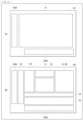
- FIG. 5 illustrates an example of the piece of mask data Dmask.
- a size of the piece of mask data Dmask corresponds to a size of the piece of image data Dpic1 ( FIGs. 3 and 4 ).
- the image region of the piece of image data Dpic1 is segmented into 80 segmented regions A: sixteen segmented regions A in the lateral direction (the horizontal direction) by five segmented regions A in the longitudinal direction (the vertical direction).
- the image indicated by the piece of image data Dpic1 has a size of 320 pixels in the lateral direction by 240 pixels in the longitudinal direction; therefore, the segmented region A has a size of 20 pixels in the lateral direction by 48 pixels in the longitudinal direction.
- the segmented region A is a vertically long region.
- the value of the flag F in each of the plurality of segmented regions A is written in that segmented region A.
- a region in which the flag F is set to "1" is shaded.
- a person in the image illustrated in FIGs. 3 and 4 is slightly moving; therefore, the flags F in a plurality of segmented regions A corresponding to the person are set to " 1", and the flags F in a plurality of segmented regions A other than the plurality of segmented regions A corresponding to the person are set to "0".
- FIG. 6 illustrates another example of the piece of mask data Dmask.
- the image region of the piece of image data Dpic1 is segmented into segmented into 768 segmented regions A: 32 segmented regions A in the lateral direction (the horizontal direction) by 24 segmented regions A in the longitudinal direction (the vertical direction).
- the image indicated by the piece of image data Dpic1 has a size of 320 pixels in the lateral direction by 240 pixels in the longitudinal direction; therefore, the segmented region A has a size of ten pixels in the lateral direction by ten pixels in the longitudinal direction. That is, in this example, the segmented region A is a square region.
- the segmented region A is a square region.
- the signal processor 13 generates the piece of mask data Dmask.
- the recognition processor 30 performs recognition processing on a region (an operation target region C) in which the flag F is set to " 1" among the plurality of segmented regions A on the basis of the piece of mask data Dmask.
- the memory 14 ( FIG. 1 ) is configured to store a piece of data to be processed in the imaging device 1.
- the memory 14 includes, for example, a DRAM (Dynamic Random Access Memory), a SRAM (Static Random Access Memory), or the like.
- the memory 14 stores, for example, the piece of image data Dpic1 and the piece of mask data Dmask that are supplied from the signal processor 13.
- the memory 14 stores a piece of data DM (to be described later) and a piece of weighting coefficient data DW (to be described later) that are to be used when the recognition processor 30 performs recognition processing. Thereafter, the memory 14 supplies, to the communication section 15, the piece of image data Dpic1 and a piece of data indicating a processing result of recognition processing.
- the recognition processor 30 is configured to perform, for example, object recognition processing for classifying an object included in the subject.
- the recognition processor 30 may detect a position of each subject in a three-dimensional space.
- the recognition processor 30 may perform recognition processing with use of semantic segmentation technology.
- the recognition processor 30 is configured to perform recognition processing on an image region of a person or an animal in the image region of the piece of image data Dpic1.
- the recognition processor 30 is configured to classify an object into a human or an animal by performing the object recognition processing.
- the recognition processor 30 is configured to confirm whether or not a person is in an off-limits area, for example, by detecting the position of each subject in the three-dimensional space.
- the recognition processor 30 is configured to recognize, for example, a part such as an arm or a leg of the person by performing recognition processing with use of semantic segmentation technology, which makes it possible to confirm a more specific action of the person.
- the sensor controller 19 is configured to control operations of the buffer memory 12, the signal processor 13, the memory 14, and the communication section 15.
- the processor 100 is configured to perform predetermined processing on the basis of the piece of image data and the processing result of recognition processing that are supplied from the imaging device 1.
- the recognition processor 30 includes a convolution operation section 31, a post-processing operation section 32, a nonvolatile memory 33, and an operation controller 34.
- the recognition processor 30 includes, for example, a microcontroller.
- the convolution operation section 31 is configured to perform a convolution operation CONV using the neural network on the basis of an instruction from the operation controller 34.
- the convolution operation section 31 performs the convolution operation CONV in the operation target region C indicated by the piece of mask data Dmask on the basis of the piece of data DM and the piece of weighting coefficient data DW that are supplied from the memory 14.
- the post-processing operation section 32 is configured to perform a predetermined post-processing operation POST including a quantization operation and the like on a result of the operation by the convolution operation section 31 on the basis of an instruction from the operation controller 34. Thereafter, the post-processing operation section 32 stores a result of processing as the piece of data DM in the memory 14.
- the nonvolatile memory 33 includes, for example, a flash memory, and is configured to store a model parameter of the neural network and an operation parameter.
- the model parameter is to be used in recognition processing in the recognition processor 30, and the operation parameter is to be used in an update operation of the piece of mask data Dmask.
- the model parameter and the operation parameter are created with use of, for example, a software development kit (SDK: Software Development Kit), and are stored in this nonvolatile memory 33 in advance.
- SDK Software Development Kit
- the operation controller 34 is configured to control recognition processing in the recognition processor 30 by controlling operations of the convolution operation section 31 and the post-processing operation section 32, on the basis of the model parameter and the operation parameter that are supplied from the nonvolatile memory 33, and the piece of mask data Dmask supplied from the memory 14.
- the operation controller 34 stores the piece of weighting coefficient data DW included in the model parameter in the memory 14.
- the operation controller 34 also performs a function of supplying a write address when writing the piece of data DM and the piece of weighting coefficient data DW to the memory 14, and a readout address when reading the piece of data DM and the piece of weighting coefficient data DW from the memory 14.
- the operation controller 34 includes a region setting section 34A.
- the region setting section 34A is configured to update the piece of mask data Dmask on the basis of the operation parameter supplied from the nonvolatile memory 33.
- the region setting section 34A combines the flags F in two or more of segmented regions A in the piece of mask data Dmask into one flag F in accordance with the convolution operation CONV by the convolution operation section 31 to thereby update the piece of mask data Dmask.
- the region setting section 34A combines the flags F in four (2 ⁇ 2) segmented regions A in the piece of mask data Dmask into one flag F to thereby update the piece of mask data Dmask.
- FIG. 7 illustrates an operation example of the recognition processor 30.
- the convolution operation section 31 and the post-processing operation section 32 alternately perform operations.
- the convolution operation section 31 first performs, on the piece of data DM (a piece of data DM1) supplied from the memory 14, a convolution operation CONV1 using the piece of weighting coefficient data DW (a piece of weighting coefficient data DW1) supplied from the memory 14.
- the piece of data DM1 in this example is the piece of image data Dpic1 supplied from the memory 14.
- the post-processing operation section 32 performs a post-processing operation POST1 on an operation result of the convolution operation CONV1, and writes the operation result as the piece of data DM (a piece of data DM2) to the memory 14.
- the convolution operation CONV1 and the post-processing operation POST1 correspond to a layer L1.
- the convolution operation section 31 performs, on the piece of data DM2 supplied from the memory 14, a convolution operation CONV2 using the piece of weighting coefficient data DW (a piece of weighting coefficient data DW2) supplied from the memory 14.
- the post-processing operation section 32 performs a post-processing operation POST2 on an operation result of the convolution operation CONV2, and writes the operation result as the piece of data DM (a piece of data DM3) to the memory 14.
- the convolution operation CONV2 and the post-processing operation POST2 correspond to a layer L2
- the convolution operation section 31 performs, on the piece of data DM3 supplied from the memory 14, a convolution operation CONV3 using the piece of weighting coefficient data DW (a piece of weighting coefficient data DW3) supplied from the memory 14.
- the post-processing operation section 32 performs a post-processing operation POST3 on an operation result of the convolution operation CONV3, and writes the operation result as a piece of data DM4 to the memory 14.
- the convolution operation CONV3 and the post-processing operation POST3 correspond to a layer L3. The same applies thereafter.
- the convolution operation section 31 and the post-processing operation section 32 alternately perform the operations in such a manner.
- FIG. 8 illustrates an example of the convolution operation CONV.
- the convolution operation section 31 performs, on the piece of data DM, this convolution operation CONV using the piece of weighting coefficient data DW.
- the piece of data DM in this example includes two pieces of map data (pieces of map data M1 and M2). That is, in this example, the piece of data DM includes pieces of data with two channels.
- the piece of weighting coefficient data DW in this example includes pieces of coefficient data W1A, W2A, W1B, W2B, W1C, and W2C.
- the pieces of coefficient data W1A, W1B, and W1C are associated with the piece of map data M1.
- the pieces of coefficient data W2A, W2B, and W2C are associated with the piece of map data M2.
- the convolution operation section 31 performs a convolution operation using the piece of coefficient data W1A on the piece of map data M1, and performs a convolution operation using the piece of coefficient data W2A on the piece of map data M2, thereby generating a piece of map data (a piece of map data MA). Specifically, for example, the convolution operation section 31 first sets a convolution operation region having a size of 2 ⁇ 2 at the upper left in each of the pieces of map data M1 and M2.
- the convolution operation section 31 performs a multiplication of a piece of data (a hatched part) in the convolution operation region of the piece of map data M1 by the piece of coefficient data W1A, performs a multiplication of a piece of data (a hatched part) in the convolution operation region of the piece of map data M2 by the piece of coefficient data W2A, and adds results of these multiplications together, thereby calculating a piece of data (a hatched part) on the far left in an uppermost row in the piece of map data MA.
- the convolution operation section 31 shifts the convolution operation region in the piece of map data M1 to the right by two.
- the convolution operation section 31 performs a multiplication of a piece of data in the convolution operation region of the piece of map data M1 by the piece of coefficient data W1A, performs a multiplication of a piece of data in the convolution operation region of the piece of map data M2 by the piece of coefficient data W2A, and adds results of these multiplications together, thereby calculating the second piece of data from the left in the uppermost row in the piece of map data MA.
- the convolution operation section 31 sequentially changes the convolution operation regions in the pieces of map data M1 and M2, and performs a similar operation.
- the convolution operation section 31 generates the piece of map data MA.
- the convolution operation section 31 performs, on the pieces of map data M1 and M2 with two channels, the convolution operation using 2 ⁇ 2 kernels (the pieces of coefficient data W1A, W2A, and W3A) with three channels, thereby generating the piece of map data MA.
- a size in the lateral direction of the piece of map data MA is a half of a size in the lateral direction of each of the pieces of map data M1 and M2, and a size in the longitudinal direction of the piece of map data MA is a half of a size in the longitudinal direction of each of the pieces of map data M1 and M2.
- the size of the piece of map data M is reduced.
- the convolution operation section 31 performs a convolution operation using the piece of coefficient data W1B on the piece of map data M1, and performs a convolution operation using the piece of coefficient data W2B on the piece of map data M2, thereby generating the piece of map data M (a piece of map data MB).
- the convolution operation section 31 performs a convolution operation using the piece of coefficient data W1C on the piece of map data M1, and performs a convolution operation using the piece of coefficient data W2C on the piece of map data M2, thereby generating the piece of map data M (a piece of map data MC).
- the convolution operation section 31 generates pieces of data with three channels in this example.
- the convolution operation section 31 performs such a convolution operation CONV in the operation target region C indicated by the piece of mask data Dmask on the basis of the piece of mask data Dmask.
- the region setting section 34A of the operation controller 34 updates the piece of mask data Dmask every time the convolution operation section 31 performs the convolution operation CONV.
- FIG. 9 illustrates an operation example of the region setting section 34A. As described above, the size of the piece of map data M included in the piece of data DM is reduced every time the convolution operation section 31 performs the convolution operation CONV using the piece of weighting coefficient data DW.
- the region setting section 34A combines the flags F in four (2 ⁇ 2) segmented regions A in the piece of mask data Dmask into one flag F. This causes the region setting section 34A to reduce the size of the piece of mask data Dmask by half in the lateral direction and by half in the longitudinal direction.
- the region setting section 34A combines the flags F in nine (3 ⁇ 3) segmented regions A in the piece of mask data Dmask into one flag F. This causes the region setting section 34A to reduce the size of the piece of mask data Dmask to 1/3 in the lateral direction and to 1/3 in the longitudinal direction.
- the region setting section 34A updates the piece of mask data Dmask, which causes the size of the piece of mask data Dmask to be equal to the size of the piece of map data M.
- FIG. 10 illustrates an example of writing of the model parameter to the imaging device 1.
- the model parameter is generated by, for example, an information processing device 90.
- the information processing device 90 is, for example, a personal computer.
- a software development kit (SDK) 92 is installed in a storage section 91 of the information processing device 90.
- the storage section 91 includes, for example, an HDD (Hard Disk Drive) or an SSD (Solid State Drive).
- the information processing device 90 executes the software development kit 92 to perform machine learning processing, thereby generating a model parameter MP of the neural network.
- the model parameter MP is stored in the storage section 91.
- the model parameter MP includes a plurality of pieces of weighting coefficient data DW (pieces of weighting coefficient data DW1, DW2, DW3, ...) illustrated in FIG. 5 , for example.
- an operation parameter corresponding to the certain piece of weighting coefficient data DW is a parameter that causes the region setting section 34A to perform an operation for combining the flags F in nine (3 ⁇ 3) segmented regions A in the piece of mask data Dmask into one flag F.
- the information processing device 90 generates the operation parameters corresponding to the plurality of respective pieces of weighting coefficient data DW to thereby generate the operation parameter PP.
- the operation parameter PP is stored in the storage section 91.
- the information processing device 90 writes the model parameter MP and the operation parameter PP as pieces of data to the nonvolatile memory 33 of the imaging device 1. Specifically, the information processing device 90 writes this model parameter MP and this operation parameter PP to the nonvolatile memory 33 with use of a write control command generated by the software development kit 92. This allows the recognition processor 30 of the imaging device 1 to perform recognition processing with use of the model parameter MP and the operation parameter PP.
- the imaging device 1 may be formed on one semiconductor substrate, or may be formed on a plurality of semiconductor substrates. An example in which the imaging device 1 is formed on two semiconductor substrates is described in detail below.
- FIG. 11 illustrates an implementation example of the imaging device 1.
- the imaging device 1 is formed on two semiconductor substrates 101 and 102.
- the semiconductor substrate 101 is provided on side of an imaging surface S of the imaging device 1, and the semiconductor substrate 102 is provided on side opposite to the imaging surface S of the imaging device 1.
- the semiconductor substrates 101 and 102 are superimposed on each other.
- a wiring of the semiconductor substrate 101 and a wiring of the semiconductor substrate 102 are coupled to each other by a coupling section 103. It is possible to use, for example, a through silicon via (TSV: Through Silicon Via), Cu-Cu bonding, a microbump, or the like for the coupling section 103.
- TSV Through Silicon Via
- FIG. 12 illustrates a layout example of respective circuits of the imaging device 1 on the semiconductor substrates 101 and 102.
- the pixel array 21 is provided on the semiconductor substrate 101.
- the coupling section 103 (coupling sections 103A and 103B) is provided in regions corresponding to each other on the semiconductor substrates 101 and 102. Specifically, the coupling section 103A is provided around left sides of the semiconductor substrates 101 and 102, and the coupling section 103B is provided around lower sides of the semiconductor substrates 101 and 102.
- a driving section 22 is provided on the right of the coupling section 103A on the semiconductor substrate 102.
- the driving section 22 generates a control signal, and supplies the control signal to the plurality of light-receiving pixels P of the pixel array 21 via the coupling section 103A on the semiconductor substrates 101 and 102.
- the AD converter 23 is provided above the coupling section 103B. Accordingly, a pixel signal supplied from the pixel array 21 is supplied to the AD converter 23 via the coupling section 103B on the semiconductor substrates 101 and 102.
- the horizontal scanner 24 is provided above the AD converter 23.
- the sensor controller 19 is provided around a middle of the semiconductor substrate 102, and the signal processor 13 is provided above the sensor controller 19.
- the memory 14 and the recognition processor 30 are provided on the right of the sensor controller 19.
- the peripheral circuit 110 is another circuit, and is provided on the left of the sensor controller 19 and the signal processor 13.
- the peripheral circuit 110 includes, for example, a phase locked loop (PLL: Phase Locked Loop), a LDO (Low Drop Out) regulator, a charge pump, or the like.
- PLL Phase Locked Loop
- LDO Low Drop Out
- the region setting section 34A corresponds to a specific example of a "region setting section” in an embodiment of the present disclosure.
- the piece of mask data Dmask corresponds to a specific example of a "piece of flag data” in an embodiment of the present disclosure.
- the piece of image data Dpic1 corresponds to a specific example of a "piece of image data” in an embodiment of the present disclosure.
- the operation target region C corresponds to a specific example of an "operation target region” in an embodiment of the present disclosure.
- the convolution operation section 31 corresponds to a specific example of a "convolution operation section” in an embodiment of the present disclosure.
- the piece of weighting coefficient data DW1 corresponds to a specific example of a "piece of first weighting coefficient data" in an embodiment of the present disclosure.
- the imaging section 11 corresponds to a specific example of a "photodetecting section” in an embodiment of the present disclosure.
- the imaging section 11 performs an imaging operation of imaging a subject, and outputs a result of the imaging as the piece of image data Dpic.
- the buffer memory 12 temporarily stores the piece of image data Dpic supplied from the imaging section 11.
- the signal processor 13 generates the piece of image data Dpic1 and the piece of mask data Dmask on the basis of the piece of image data Dpic supplied from the buffer memory 12.
- the motion detector 13A of the signal processor 13 compares, for example, a latest image with a past image to thereby detect motion of a subject.
- the memory 14 stores, for example, the piece of image data Dpic1 and the piece of mask data Dmask that are supplied from the signal processor 13.
- the memory 14 stores the piece of image data DM and the piece of weighting coefficient data DW that are to be used when the recognition processor 30 performs recognition processing.
- the recognition processor 30 performs recognition processing using the neural network on the basis of pieces of data stored in the memory 14.
- the communication section 15 transmits, to the processor 100, a piece of image data and a piece of data indicating a processing result of recognition processing that are supplied from the memory 14.
- the sensor controller 19 controls operations of the buffer memory 12, the signal processor 13, the memory 14, and the communication section 15.
- the convolution operation section 31 performs the convolution operation CONV using the neural network on the basis of an instruction from the operation controller 34.
- the post-processing operation section 32 performs the predetermined post-processing operation POST including a quantization operation and the like on a result of the operation by the convolution operation section 31 on the basis of an instruction from the operation controller 34.
- the nonvolatile memory 33 stores the model parameter of the neural network to be used in recognition processing in the recognition processor 30, and the operation parameter to be used in the update operation of the piece of mask data Dmask.
- the operation controller 34 controls operations of the convolution operation section 31 and the post-processing operation section 32 on the basis of the model parameter supplied from the nonvolatile memory 33 to thereby control recognition processing in the recognition processor 30.
- the region setting section 34A of the operation controller 34 updates the piece of mask data Dmask on the basis of the operation parameter supplied from the nonvolatile memory 33.
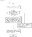
- FIG. 13 illustrates an example of an operation of generating the piece of mask data Dmask in the signal processor 13.
- the motion detector 13A of the signal processor 13 compares a latest frame image with a frame image previous to the latest frame image (step S101).
- the motion detector 13A confirms whether or not a difference between two frame images is larger than or equal to a predetermined reference (step S102).
- step S102 in a case where the difference between the two frame image is larger than or equal to the predetermined reference ("Y" in step S102), the motion detector 13A specifies the segmented region A having a motion amount larger than or equal to a predetermined amount from among the plurality of segmented regions A to thereby generate the piece of mask data Dmask (step S103).
- the motion detector 13A sets, to "1", the flag F in the segmented region A having a motion amount larger than or equal to the predetermined amount specified from among the plurality of segmented regions A, and sets the flags in the other segmented regions A to "0", thereby generating the piece of mask data Dmask.
- step S102 in a case where the difference between the two frame images is not larger than or equal to the predetermined reference ("N" in step S102), the motion detector 13A generates the piece of mask data Dmask in which the flags F in all the plurality of segmented regions A are "0" (step S104).
- the signal processor 13 stores the piece of image data Dpic1, and the generated piece of mask data Dmask in the memory 14 (step S105).
- the recognition processor 30 performs recognition processing using the neural network on the basis of these pieces of data stored in the memory 14.
- FIG. 14 illustrates an operation example of the recognition processor 30.
- the operation controller 34 sets a first layer as an operation target layer (step S111).
- the operation controller 34 sets a readout address of a piece of data included in the piece of data DM to be used in a convolution operation (step S112).
- the operation controller 34 reads the piece of mask data Dmask from the memory 14, and confirms whether or not the piece of data stored at the readout address in the memory 14 is a piece of data in the operation target region C, with use of this piece of mask data Dmask (step S113). In a case where the piece of data is not the piece of data in the operation target region C ("N" in step S114), processing returns to step S112.
- step S114 in a case where the piece of data is the piece of data in the operation target region C ("Y" in step S114), the recognition processor 30 reads the piece of data from the memory 14 with use of the set readout address (step S115).
- the convolution operation section 31 performs the convolution operation CONV (step S116). Specifically, the convolution operation section 31 reads the piece of weighting coefficient data DW from the memory 14, and performs the convolution operation CONV on the piece of data read in the step S115 with use of this piece of weighting coefficient data DW. Thus, the convolution operation section 31 performs the convolution operation CONV on the piece of data in the operation target region C.
- the post-processing operation section 32 performs the post-processing operation POST (step S117). Specifically, the post-processing operation section 32 performs a predetermined post-processing operation POST including a quantization operation and the like on a result of the operation by the convolution operation section 31. Thereafter, the post-processing operation section 32 stores a result of processing as the piece of data DM in the memory 14.
- step S118 the operation controller 34 confirms whether or not all operations in the set operation target layer have been completed. In a case where all the operations in the operation target layer have not yet been completed ("N" in step S118), the processing returns to step S112.
- the recognition processor 30 repeats processing from step S112 to step S118 until all operations in the set operation target layer have been completed. In this way, the recognition processor 30 performs the convolution operation CONV on the piece of data in the operation target region C in the operation target layer, and performs the post-processing operation POST on the basis of an operation result of the convolution operation CONV.
- step S118 in a case where all the operations in the operation target layer have been completed ("Y" in step S118), the operation controller 34 confirms whether or not operations in all layers have been completed (step S119).
- step S119 in a case where the operations in all the layers have not yet been completed ("N" in step S119), the operation controller 34 sets the next layer as the operation target layer, and updates the piece of mask data Dmask (step S120).
- the region setting section 34A updates the piece of mask data Dmask on the basis of the operation parameter supplied from the nonvolatile memory 33. Accordingly, for example, as illustrated in FIG. 9 , the size of the piece of mask data Dmask becomes equal to the size of the piece of map data M.
- the processing returns to step S112.
- the recognition processor 30 repeats processing from step S112 to step S120 until the operations in all the layers have been completed.
- step S119 in a case where the operations in all the layers have been completed ("Y" in step S119), this flow ends.
- FIG. 15 illustrates an operation example of the region setting section 34A, where (A) illustrates an example of the piece of mask data Dmask in a certain layer, (B) illustrates an example of the piece of mask data Dmask in a layer next to the certain layer, and (C) illustrates the piece of mask data Dmask in a layer after the next layer.
- the piece of mask data Dmask is a piece of data illustrated in FIG. 6 .
- the convolution operation section 31 performs the convolution operation CONV using a 2 ⁇ 2 kernel. Accordingly, as illustrated in FIG. 8 , the size of the piece of map data M is reduced by half in the lateral direction and reduced by half in the longitudinal direction.
- the region setting section 34A combines the flags F in four (2 ⁇ 2) segmented regions A in the piece of mask data Dmask into one flag F. This causes the region setting section 34A to reduce the size of the piece of mask data Dmask by half in the lateral direction and by half in the longitudinal direction.
- the size of the piece of mask data Dmask illustrated in FIG. 15 is the same; therefore, the size of the segmented region A is relatively doubled in the lateral direction and doubled in the longitudinal direction at each time of progressing through one layer.
- the flags F in four segmented regions A in a region W1 are all "1". Accordingly, the region setting section 34A sets the flag F to "1" in the segmented region A at the upper left corresponding to this region W1 in the piece of mask data Dmask ((B) of FI. 15) in the next layer.
- two flags F are "1"
- the remaining two flags F are "0".
- the region setting section 34A sets the flag F in one segmented region A corresponding to the four segmented regions A in the next layer to "1". Accordingly, in this example, the region setting section 34A sets the flag F in the segmented region A corresponding to this region W2 in the piece of mask data Dmask in the next layer ((B) of FIG. 15) to "1 ". That is.
- a method of generating one flag F by combining four flags in four segmented regions A is not limited to the method described above.
- the region setting section 34A may set the flag F in one segmented region A corresponding to the four segmented regions A in the next layer to "1".
- the region setting section 34A may set the flag F in one segmented region A corresponding to the four segmented regions A in the next layer to "1". This method may be set by a user, or may be set by machine learning when the information processing device 90 performs machine learning of a model parameter.
- the region setting section 34A sets the flag F in the segmented region A at the upper left corresponding to the region W3 in the piece of mask data Dmask ((C) of FI. 15) in the next layer to "1".
- two flags F are "1"
- the remaining two flags F are "0". Accordingly, in this example, the region setting section 34A sets the flag F to "1" in the segmented region A corresponding to the region W4 in the piece of mask data Dmask in the next layer ((C) of FIG. 15 ).
- the region setting section 34A updates the piece of mask data Dmask.
- the flags F are "1".
- the region setting section 34A repeats the update operation of the piece of mask data Dmask, thereby making it possible to combine regions in which the flags F are "1" into one region, as illustrated in (C) of FIG. 15 .
- the region setting section 34A performs such update processing on the piece of mask data Dmask with use of a dedicated command set in the microcontroller. This allows the region setting section 34A to perform update processing on the piece of mask data Dmask in one cycle, for example. If the region setting section 34A performs update processing on the piece of mask data Dmask with use of a basic logical operation command set in the microcontroller, there is a possibility that the operation amount increases because a plurality of commands is executed. For example, preparing the dedicated command set makes it possible for the region setting section 34A to efficiently perform operation processing.
- the imaging device 1 includes the region setting section 34A and the convolution operation section 31.
- the region setting section 34A is configured to set the operation target region C on the basis of the piece of mask data Dmask indicating a region to be processed and a region not to be processed in an image region indicated by the piece of image data Dpic1.
- the operation target region C is an image region that has to be processed in the image region indicated by the piece of image data.
- the convolution operation section 31 is configured to perform the convolution operation CONV in the operation target region C on the basis of the piece of image data Dpic and a piece of first weighting coefficient data (the piece of weighting coefficient data DW1). Accordingly, in the imaging device 1, it is possible to reduce an operation amount.
- the imaging device 1 includes the region setting section 34A that is configured to set the operation target region C, and the convolution operation section 31 performs the convolution operation in this operation target region C, which makes it possible to perform the convolution operation only in the operation target region C. Accordingly, it is possible to reduce the operation amount and it is possible to reduce power consumption.
- the region setting section 34A is configured to update the operation target region C on the basis of the operation parameter associated with the piece of first weighting coefficient data (the piece of weighting coefficient data DW1), and the convolution operation section 31 is configured to further perform the convolution operation CONV in the updated operation target region C on the basis of an operation result of the previous convolution operation CONV and a piece of second weighting coefficient data (the piece of weighting coefficient data DW1). Accordingly, the convolution operation section 31 is configured to perform the convolution operation in the updated operation target region C also in the second layer. This makes it possible to reduce the operation amount, and makes it possible to reduce power consumption.
- the piece of mask data Dmask includes a piece of map data corresponding to the piece of image data Dpic1, and resolution of the piece of mask data Dmask is lower than resolution of the piece of image data Dpic1. This makes it possible to reduce an amount of data to be handled, for example, as compared with a case where the resolution of the piece of mask data Dmask is high, which makes it possible to simplify processing, and makes it possible to effectively perform the convolution operation.
- the imaging section 11 is provided that is configured to perform an imaging operation, and motion of a subject is detectable on the basis of a result of imaging by the imaging section 11, and it is possible to generate the piece of mask data Dmask on the basis of the motion of the subject. This makes it possible to set, for example, an image region in which the subject is moving as the operation target region in the image region indicated by the piece of image data, which makes it possible to effectively perform recognition processing.
- a region setting section and a convolution operation section are included.
- the region setting section is configured to set an operation target region on the basis of a piece of mask data that indicates a region to be processed and a region not to be processed in an image region indicated by a piece of image data.
- the operation target region is an image region that has to be processed in the image region indicated by the piece of image data.
- the convolution operation section is configured to perform a convolution operation in the operation target region C on the basis of the piece of image data and the piece of first weighting coefficient data. Accordingly, it is possible to reduce an operation amount.
- the region setting section is configured to update the operation target region on the basis of an operation parameter associated with the piece of first weighting coefficient data
- the convolution operation section is configured to further perform the convolution operation in the updated operation target region on the basis of an operation result of the previous convolution operation and the piece of second weighting coefficient data, which makes it possible to reduce the operation amount.
- the piece of mask data includes a piece of map data corresponding to the piece of image data, and resolution of the piece of mask data is lower than resolution of the piece of image data.
- an imaging section is provided that is configured to perform an imaging operation, and motion of a subject is detectable on the basis of a result of imaging by the imaging section, and it is possible to generate the piece of mask data on the basis of the motion of the subject.
- the piece of data in the operation target region C of the piece of data DM is read from the memory 14, but this is not limitative. Instead of this, for example, all pieces of data in the piece of data DM may be read from the memory 14, and the convolution operation section 31 may perform the convolution operation on the piece of data in the operation target region C among the read pieces of data.
- the operation controller 34 is configured to give an invalidity instruction to the convolution operation section 31 so as not to perform the convolution operation on pieces of data in regions other than the operation target region C.
- the plurality of light-receiving pixels P in the pixel array 21 is arranged in units U of four light-receiving pixels P including the light-receiving pixel P provided with the red (R) color filter, the light-receiving pixels P provided with the green (Gr and Gb) color filters, and the light-receiving pixel P provided with the blue (B) color filter, but this is not limitative.
- the present modification example is described in detail below.
- FIG. 17 illustrates a configuration example of the unit U according to the present modification example.
- the plurality of light-receiving pixels P is arranged in units U of sixteen light-receiving pixels P.
- the sixteen light-receiving pixels P in the unit U are arranged in four rows and four columns.
- the light-receiving pixels P provided with the red (R) color filters are arranged in two rows and two columns at the upper left
- the light-receiving pixels P provided with the green (Gr) color filters are arranged in two rows and two column at the upper right
- the light-receiving pixels P provided with the green (Gb) color filters are arranged in two rows and two columns at the lower left
- the light-receiving pixels P provided with the blue (B) color filters are arranged in two rows and two columns at the lower right.
- FIG. 18 illustrates a configuration example of the unit U according to the present modification example.
- the plurality of light-receiving pixels P is arranged in units U of thirty six light-receiving pixels P.
- the thirty six light-receiving pixels in the unit U are arranged in six rows and six columns.
- the light-receiving pixels P provided with the red (R) color filters are arranged in three rows and three columns at the upper left
- the light-receiving pixels P provided with the green (Gr) color filters are arranged in three rows and three column at the upper right
- the light-receiving pixels P provided with the green (Gb) color filters are arranged in three rows and three columns at the lower left
- the light-receiving pixels P provided with the blue (B) color filters are arranged in three rows and three columns at the lower right.
- FIG. 19 illustrates a configuration example of the unit U according to the present modification example.
- the plurality of light-receiving pixels P is arranged in units U of four light-receiving pixels P.
- the four light-receiving pixels P in the unit U are arranged in two rows and two columns.
- the light-receiving pixel P provided with the red (R) color filter is provided at the upper left
- the light-receiving pixel P provided with a yellow (Y) color filter is provided at the upper right
- the light-receiving pixel P provided with a green (G) color filter is provided at the lower left
- the light-receiving pixel P provided with the blue (B) color filter is provided at the lower right.
- the yellow (Y) color filter is what is called a complementary color filter.
- FIG. 20 illustrates a configuration example of the unit U according to the present modification example.
- a pixel pair including two light-receiving pixels P provided with the red (R) color filters is provided at the upper left
- a pixel pair including two light-receiving pixels P provided with the green (Gr) color filters is provided at the upper right
- a pixel pair including two light-receiving pixels P provided with the green (Gb) color filters is provided at the lower left
- a pixel pair including two light-receiving pixels P provided with the blue (B) color filters is provided at the lower right.
- the two light-receiving pixels P included in the pixel pair are what is called phase-difference pixels.
- One on-chip lens is provided for these two light-receiving pixels P. Accordingly, in the two light-receiving pixels P, images are shifted from each other. Thus, in the imaging device 1, it is possible to generate the piece of image data Dpic, and also generate a piece of phase-difference data on the basis of what is called an image plane phase difference detected by a plurality of pixel pairs.
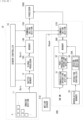
- the imaging device 1C includes the imaging section 11, the buffer memory 12, the signal processor 13, a memory 14C, a communication section 15C, and the sensor controller 19.
- the memory 14C is configured to store, for example, the piece of image data Dpic1 and the piece of mask data Dmask that are supplied from the signal processor 13.
- the communication section 15C is configured to transmit the piece of image data Dpic1 supplied from the memory 14C to the processor 100C and transmit, to the recognition processing device 30C, the piece of image data Dpic1 and the piece of mask data Dmask that are supplied from the memory 14C.
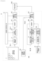
- the motion detector 13A of the signal processor 13 detects motion of the subject on the basis of the piece of image data Dpic, but this is not limitative. Instead of this, for example, as illustrated in FIG. 22 , another sensor may detect motion.
- This system includes an imaging device 1D, a motion sensor 41D, a recognition processing device 30D, and the processor 100C.
Landscapes
- Engineering & Computer Science (AREA)
- Multimedia (AREA)
- Theoretical Computer Science (AREA)
- Physics & Mathematics (AREA)
- General Physics & Mathematics (AREA)
- Software Systems (AREA)
- Evolutionary Computation (AREA)
- Signal Processing (AREA)
- Computer Vision & Pattern Recognition (AREA)
- Health & Medical Sciences (AREA)
- Artificial Intelligence (AREA)
- General Health & Medical Sciences (AREA)
- Biomedical Technology (AREA)
- Life Sciences & Earth Sciences (AREA)
- Computing Systems (AREA)
- Molecular Biology (AREA)
- Computational Linguistics (AREA)
- Data Mining & Analysis (AREA)
- General Engineering & Computer Science (AREA)
- Mathematical Physics (AREA)
- Biophysics (AREA)
- Databases & Information Systems (AREA)
- Medical Informatics (AREA)
- Human Computer Interaction (AREA)
- Biodiversity & Conservation Biology (AREA)
- Image Processing (AREA)
- Image Analysis (AREA)
Abstract
An image processing device according to an embodiment of the present disclosure includes: a region setting section that is configured to set an operation target region on the basis of a piece of flag data that indicates a region to be processed and a region not to be processed in an image region indicated by a piece of image data, the operation target region being an image region that has to be processed in the image region indicated by the piece of image data; and a convolution operation section that is configured to perform a convolution operation in the operation target region on the basis of the piece of image data and a piece of first weighting coefficient data.
Description
- The present disclosure relates to an image processing device that performs processing using a neural network.
- An image processing device frequently performs a convolution operation using a neural network. For example,
PTL 1 discloses an identification device that includes a classifier in order to achieve reduction in operation amount. The classifier performs determination on each of a plurality of pieces of partial data obtained from a piece of intermediate data as to whether or not to continue operation processing. - PTL 1:
Japanese Unexamined Patent Application Publication No. 2019-200648 - As described above, in an image processing device, reduction in operation amount is desired, and it is expected to further reduce the operation amount.
- It is desirable to provide an image processing device that makes it possible to reduce an operation amount.
- An image processing device according to one embodiment of the present disclosure includes a region setting section and a convolution operation section. The region setting section is configured to set an operation target region on the basis of a piece of flag data that indicates a region to be processed and a region not to be processed in an image region indicated by a piece of image data. The operation target region is an image region that has to be processed in the image region indicated by the piece of image data. The convolution operation section is configured to perform a convolution operation in the operation target region on the basis of the piece of image data and a piece of first weighting coefficient data.
- In the image processing device according to one embodiment of the present disclosure, the region setting section sets the operation target region on the basis of the piece of flag data that indicates the region to be processed and the region not to be processed in the image region indicated by the piece of image data. The operation target region is the image region that has to be processed in the image region indicated by the piece of image data. Thereafter, the convolution operation section performs the convolution operation in the operation target region on the basis of the piece of image data and the piece of first weighting coefficient data.
-
- [
FIG. 1] FIG. 1 is a block diagram illustrating a configuration example of an imaging device according to an embodiment of the present disclosure. - [
FIG. 2] FIG. 2 is a block diagram illustrating a configuration example of an imaging section illustrated inFIG. 1 . - [
FIG. 3] FIG. 3 is an explanatory diagram illustrating an example of a piece of image data illustrated inFIG. 1 . - [
FIG. 4] FIG. 4 is an explanatory diagram illustrating another example of the piece of image data illustrated inFIG. 1 . - [
FIG. 5] FIG. 5 is an explanatory diagram illustrating an example of a piece of mask data illustrated inFIG. 1 . - [
FIG. 6] FIG. 6 is an explanatory diagram illustrating another example of the piece of mask data illustrated inFIG. 1 . - [
FIG. 7] FIG. 7 is an explanatory diagram illustrating an operation example of a recognition processor illustrated inFIG. 1 . - [
FIG. 8] FIG. 8 is an explanatory diagram illustrating an operation example of a convolution operation to be performed by a convolution operation section illustrated inFIG. 1 . - [
FIG. 9] FIG. 9 is an explanatory diagram illustrating an operation example of a region setting section illustrated inFIG. 1 . - [
FIG. 10] FIG. 10 is an explanatory diagram illustrating an example of writing of a model parameter and an operation parameter to the imaging device illustrated inFIG. 1 . - [
FIG. 11 ]FIG. 12 is an explanatory diagram illustrating an implementation example of the imaging device illustrated inFIG. 1 . - [
FIG. 12] FIG. 12 is an explanatory diagram illustrating a layout example of respective circuits on semiconductor substrates illustrated inFIG. 11 . - [
FIG. 13] FIG. 13 is an explanatory diagram illustrating an operation example of the imaging device illustrated inFIG. 1 . - [
FIG. 14] FIG. 14 is another explanatory diagram illustrating an operation example of the imaging device illustrated inFIG. 1 . - [
FIG. 15] FIG. 15 is an explanatory diagram illustrating an operation example of the region setting section illustrated inFIG. 1 . - [
FIG. 16] FIG. 16 is an explanatory diagram illustrating a configuration example of a pixel array illustrated inFIG. 1 . - [
FIG. 17] FIG. 17 is an explanatory diagram illustrating another configuration example of a pixel array according to a modification example. - [
FIG. 18] FIG. 18 is an explanatory diagram illustrating another configuration example of a pixel array according to another modification example. - [
FIG. 19] FIG. 19 is an explanatory diagram illustrating another configuration example of a pixel array according to another modification example. - [
FIG. 20] FIG. 20 is an explanatory diagram illustrating another configuration example of a pixel array according to another modification example. - [
FIG. 21] FIG. 21 is a block diagram illustrating a configuration example of a recognition processing device according to another modification example. - [
FIG. 22] FIG. 22 is a block diagram illustrating a configuration example of a recognition processing device according to another modification example. - [
FIG. 23] FIG. 23 is a block diagram illustrating a configuration example of a recognition processing device according to another modification example. - [
FIG. 24] FIG. 24 is a block diagram illustrating a configuration example of a recognition processing device according to another modification example. - In the following, some embodiments of the present disclosure are described in detail with reference to the drawings.
-
FIG. 1 illustrates a configuration example of an imaging processing device (an imaging device 1) according to an embodiment. Theimaging device 1 images a subject and performs recognition processing on the basis of a result of the imaging. Theimaging device 1 includes animaging section 11, abuffer memory 12, asignal processor 13, amemory 14, acommunication section 15, asensor controller 19, and arecognition processor 30. - The
imaging section 11 is configured to perform an imaging operation of imaging a subject and output a result of the imaging as a piece of image data Dpic. -
FIG. 2 illustrates a configuration example of theimaging section 11. Theimaging section 11 includes apixel array 21, adriving section 22, an AD (Analog to Digital)converter 23, and ahorizontal scanner 24. - The
pixel array 21 includes a plurality of control lines CTRL, a plurality of signal lines VSL, and a plurality of light-receiving pixels P. The plurality of control lines CTRL is provided to extend in a lateral direction (a horizontal direction) inFIG. 2 . The plurality of control lines CTRL each has one end coupled to thedriving section 22. The plurality of signal lines VSL is provided to extend in a longitudinal direction (a vertical direction) inFIG. 2 . The plurality of signal lines VSL each has one end coupled to theAD converter 23. The plurality of light-receiving pixels P is arranged in a matrix in thepixel array 21. The plurality of light-receiving pixels P includes a light-receiving pixel provided with a red (R) color filter, light-receiving pixels provided with green (Gr and Gb) color filters, and a light-receiving pixel provided with a blue (B) color filter. In thepixel array 21, the plurality of light-receiving pixels P is arranged in units U of four light-receiving pixels P. The four light-receiving pixels P in the unit U are arranged in two rows and two columns. In this unit U, the light-receiving pixel P provided with the red (R) color filter is provided at the upper left, the light-receiving pixel P provided with the green (Gr) color filter is provided at the upper right, the light-receiving pixel P provided with the green (Gb) color filter is provided at the lower left, and the light-receiving pixel P provided with the blue (B) color filter is provided at the lower right. In this way, the light-receiving pixels P are arranged in what is called a Bayer arrangement. Each of the plurality of light-receiving pixels P is coupled to the control line CTRL, and is coupled to the signal line VSL. The light-receiving pixels P each operate on the basis of a control signal supplied via the control line CTRL, and each output a pixel signal including a pixel voltage corresponding to an amount of received light to the signal line VSL. - The
AD converter 23 is configured to convert pixel voltages corresponding to the amount of received light into pixel values corresponding to the amount of received light by performing AD conversion on the basis of a plurality of pixel signals supplied from thepixel array 21 via the plurality of signal lines VSL. TheAD converter 23 converts pixel voltages related to the light-receiving pixels P for one row supplied from thepixel array 21 into pixel values related to the light-receiving pixels P for one row, and supplies the pixel values related to the light-receiving pixels P for one row to thehorizontal scanner 24. TheAD converter 23 repeats this operation to thereby generate pixel values of all the light-receiving pixels P in the pixel array. - The
horizontal scanner 24 is configured to sequentially output the pixel values related to the light-receiving pixels P for one row supplied from theAD converter 23 by performing a scanning operation. Thehorizontal scanner 24 repeats this operation to thereby output the pixel values of all the light-receiving pixels P in thepixel array 21 as the piece of image data Dpic. - With such a configuration, the
imaging section 11 performs an imaging operation and outputs a result of the imaging as the piece of image data Dpic. - The buffer memory 12 (
FIG. 1 ) is configured to temporarily store the piece of image data Dpic supplied from theimaging section 11. - The
signal processor 13 is configured to generate a piece of image data Dpic1 and a piece of mask data Dmask on the basis of the piece of image data Dpic supplied from thebuffer memory 12. Specifically, thesignal processor 13 performs, for example, various types of image processing such as demosaic processing, noise removal processing or black level adjustment processing on the piece of image data Dpic to thereby generate the piece of image data Dpic1, and generate the piece of mask data Dmask on the basis of the piece of image data Dpic. - The
signal processor 13 includes amotion detector 13A. Themotion detector 13A is configured to detect motion of a subject. Specifically, themotion detector 13A detects motion of the subject, for example, by comparing a latest image with a past image. Themotion detector 13A segments an image region of the piece of image data Dpic1 into a plurality of regions (segmented regions A), and detects motion of the subject in each of the plurality of segmented regions A. Thereafter, themotion detector 13A sets a flag F to "1" in a certain segmented region A in which the subject is moving among the plurality of segmented regions A, and sets the flag F to "0" in the segmented region A in which no subject is moving among the plurality of segmented regions A. Thereafter, thesignal processor 13 generates the piece of mask data Dmask including a piece of map data about the flags F in the plurality of segmented regions A. -
FIG. 3 illustrates an example of an image indicated by the piece of image data Dpic1. In this example, the image has resolution of 320 × 240. It is to be noted that the resolution of the image is not limited to this resolution, and may be higher than this resolution or may be lower than this resolution. The image may be a color image or a gray-scale image. The color image may be, for example, an RGB image including a red image, a green image, and a blue image, or a CMYK image including a cyan image, a magenta image, a yellow image, and a black image. In addition, the image may be an image before being subjected to demosaic processing, that is, what is called a RAW image. In addition, the image may be, for example, what is called an edge image, as illustrated inFIG. 4 . The edge image has a large pixel value in a region around an outline of the subject and has a small pixel value in a region other than the region around the outline of the subject. -
FIG. 5 illustrates an example of the piece of mask data Dmask. A size of the piece of mask data Dmask corresponds to a size of the piece of image data Dpic1 (FIGs. 3 and 4 ). In the example inFIG. 5 , the image region of the piece of image data Dpic1 is segmented into 80 segmented regions A: sixteen segmented regions A in the lateral direction (the horizontal direction) by five segmented regions A in the longitudinal direction (the vertical direction). In this example, the image indicated by the piece of image data Dpic1 has a size of 320 pixels in the lateral direction by 240 pixels in the longitudinal direction; therefore, the segmented region A has a size of 20 pixels in the lateral direction by 48 pixels in the longitudinal direction. That is, in this example, the segmented region A is a vertically long region. InFIG. 5 , the value of the flag F in each of the plurality of segmented regions A is written in that segmented region A. InFIG. 5 , a region in which the flag F is set to "1" is shaded. In this example, a person in the image illustrated inFIGs. 3 and 4 is slightly moving; therefore, the flags F in a plurality of segmented regions A corresponding to the person are set to " 1", and the flags F in a plurality of segmented regions A other than the plurality of segmented regions A corresponding to the person are set to "0". -
FIG. 6 illustrates another example of the piece of mask data Dmask. In the example inFIG. 6 , the image region of the piece of image data Dpic1 is segmented into segmented into 768 segmented regions A: 32 segmented regions A in the lateral direction (the horizontal direction) by 24 segmented regions A in the longitudinal direction (the vertical direction). In this example, the image indicated by the piece of image data Dpic1 has a size of 320 pixels in the lateral direction by 240 pixels in the longitudinal direction; therefore, the segmented region A has a size of ten pixels in the lateral direction by ten pixels in the longitudinal direction. That is, in this example, the segmented region A is a square region. In this example also, as with the example inFIG. 5 , a region in which the flag F is set to "1" is shaded. In this example also, the flags F in a plurality of segmented regions A corresponding to the person in the image illustrated inFIGs. 3 and 4 are set to "1", and the flags F in a plurality of segmented regions A other than the plurality of segmented regions A corresponding to the person are set to "0". - In this way, the
signal processor 13 generates the piece of mask data Dmask. As will be described later, therecognition processor 30 performs recognition processing on a region (an operation target region C) in which the flag F is set to " 1" among the plurality of segmented regions A on the basis of the piece of mask data Dmask. - The memory 14 (
FIG. 1 ) is configured to store a piece of data to be processed in theimaging device 1. Thememory 14 includes, for example, a DRAM (Dynamic Random Access Memory), a SRAM (Static Random Access Memory), or the like. Thememory 14 stores, for example, the piece of image data Dpic1 and the piece of mask data Dmask that are supplied from thesignal processor 13. In addition, thememory 14 stores a piece of data DM (to be described later) and a piece of weighting coefficient data DW (to be described later) that are to be used when therecognition processor 30 performs recognition processing. Thereafter, thememory 14 supplies, to thecommunication section 15, the piece of image data Dpic1 and a piece of data indicating a processing result of recognition processing. - The
recognition processor 30 is configured to perform recognition processing using a neural network on the basis of a piece of data stored in thememory 14. Therecognition processor 30 performs recognition processing in the operation target region C indicated by the piece of mask data Dmask. - The
recognition processor 30 is configured to perform, for example, object recognition processing for classifying an object included in the subject. In addition, therecognition processor 30 may detect a position of each subject in a three-dimensional space. In addition, therecognition processor 30 may perform recognition processing with use of semantic segmentation technology. - For example, in a case where this
imaging device 1 is applied to a monitoring system, therecognition processor 30 is configured to perform recognition processing on an image region of a person or an animal in the image region of the piece of image data Dpic1. Therecognition processor 30 is configured to classify an object into a human or an animal by performing the object recognition processing. In addition, therecognition processor 30 is configured to confirm whether or not a person is in an off-limits area, for example, by detecting the position of each subject in the three-dimensional space. In addition, therecognition processor 30 is configured to recognize, for example, a part such as an arm or a leg of the person by performing recognition processing with use of semantic segmentation technology, which makes it possible to confirm a more specific action of the person. - The
communication section 15 is configured to transmit, to aprocessor 100, the piece of image data and the piece of data indicating the processing result of recognition processing that are supplied from thememory 14. - The
sensor controller 19 is configured to control operations of thebuffer memory 12, thesignal processor 13, thememory 14, and thecommunication section 15. - The
processor 100 is configured to perform predetermined processing on the basis of the piece of image data and the processing result of recognition processing that are supplied from theimaging device 1. - The
recognition processor 30 includes aconvolution operation section 31, apost-processing operation section 32, anonvolatile memory 33, and anoperation controller 34. Therecognition processor 30 includes, for example, a microcontroller. - The
convolution operation section 31 is configured to perform a convolution operation CONV using the neural network on the basis of an instruction from theoperation controller 34. Theconvolution operation section 31 performs the convolution operation CONV in the operation target region C indicated by the piece of mask data Dmask on the basis of the piece of data DM and the piece of weighting coefficient data DW that are supplied from thememory 14. - The
post-processing operation section 32 is configured to perform a predetermined post-processing operation POST including a quantization operation and the like on a result of the operation by theconvolution operation section 31 on the basis of an instruction from theoperation controller 34. Thereafter, thepost-processing operation section 32 stores a result of processing as the piece of data DM in thememory 14. - The
nonvolatile memory 33 includes, for example, a flash memory, and is configured to store a model parameter of the neural network and an operation parameter. The model parameter is to be used in recognition processing in therecognition processor 30, and the operation parameter is to be used in an update operation of the piece of mask data Dmask. The model parameter and the operation parameter are created with use of, for example, a software development kit (SDK: Software Development Kit), and are stored in thisnonvolatile memory 33 in advance. - The
operation controller 34 is configured to control recognition processing in therecognition processor 30 by controlling operations of theconvolution operation section 31 and thepost-processing operation section 32, on the basis of the model parameter and the operation parameter that are supplied from thenonvolatile memory 33, and the piece of mask data Dmask supplied from thememory 14. Theoperation controller 34 stores the piece of weighting coefficient data DW included in the model parameter in thememory 14. In addition, theoperation controller 34 also performs a function of supplying a write address when writing the piece of data DM and the piece of weighting coefficient data DW to thememory 14, and a readout address when reading the piece of data DM and the piece of weighting coefficient data DW from thememory 14. - The
operation controller 34 includes aregion setting section 34A. Theregion setting section 34A is configured to update the piece of mask data Dmask on the basis of the operation parameter supplied from thenonvolatile memory 33. For example, theregion setting section 34A combines the flags F in two or more of segmented regions A in the piece of mask data Dmask into one flag F in accordance with the convolution operation CONV by theconvolution operation section 31 to thereby update the piece of mask data Dmask. Specifically, as will be described later, for example, in a case where theconvolution operation section 31 performs the convolution operation using a 2×2 kernel, theregion setting section 34A combines the flags F in four (2 × 2) segmented regions A in the piece of mask data Dmask into one flag F to thereby update the piece of mask data Dmask. -
FIG. 7 illustrates an operation example of therecognition processor 30. In therecognition processor 30, theconvolution operation section 31 and thepost-processing operation section 32 alternately perform operations. Specifically, in this example, theconvolution operation section 31 first performs, on the piece of data DM (a piece of data DM1) supplied from thememory 14, a convolution operation CONV1 using the piece of weighting coefficient data DW (a piece of weighting coefficient data DW1) supplied from thememory 14. The piece of data DM1 in this example is the piece of image data Dpic1 supplied from thememory 14. Thepost-processing operation section 32 performs a post-processing operation POST1 on an operation result of the convolution operation CONV1, and writes the operation result as the piece of data DM (a piece of data DM2) to thememory 14. The convolution operation CONV1 and the post-processing operation POST1 correspond to a layer L1. Next, theconvolution operation section 31 performs, on the piece of data DM2 supplied from thememory 14, a convolution operation CONV2 using the piece of weighting coefficient data DW (a piece of weighting coefficient data DW2) supplied from thememory 14. Thepost-processing operation section 32 performs a post-processing operation POST2 on an operation result of the convolution operation CONV2, and writes the operation result as the piece of data DM (a piece of data DM3) to thememory 14. The convolution operation CONV2 and the post-processing operation POST2 correspond to a layer L2, Next, theconvolution operation section 31 performs, on the piece of data DM3 supplied from thememory 14, a convolution operation CONV3 using the piece of weighting coefficient data DW (a piece of weighting coefficient data DW3) supplied from thememory 14. Thepost-processing operation section 32 performs a post-processing operation POST3 on an operation result of the convolution operation CONV3, and writes the operation result as a piece of data DM4 to thememory 14. The convolution operation CONV3 and the post-processing operation POST3 correspond to a layer L3. The same applies thereafter. Theconvolution operation section 31 and thepost-processing operation section 32 alternately perform the operations in such a manner. -
FIG. 8 illustrates an example of the convolution operation CONV. Theconvolution operation section 31 performs, on the piece of data DM, this convolution operation CONV using the piece of weighting coefficient data DW. - The piece of data DM in this example includes two pieces of map data (pieces of map data M1 and M2). That is, in this example, the piece of data DM includes pieces of data with two channels. The piece of weighting coefficient data DW in this example includes pieces of coefficient data W1A, W2A, W1B, W2B, W1C, and W2C. Each of the pieces of coefficient data W1A, W2A, W1B, W2B, W1C, and W2C is a 2×2 kernel including four (= 2 × 2) pieces of coefficient data. The pieces of coefficient data W1A, W1B, and W1C are associated with the piece of map data M1. The pieces of coefficient data W2A, W2B, and W2C are associated with the piece of map data M2.
- In the convolution operation CONV, the
convolution operation section 31 performs a convolution operation using the piece of coefficient data W1A on the piece of map data M1, and performs a convolution operation using the piece of coefficient data W2A on the piece of map data M2, thereby generating a piece of map data (a piece of map data MA). Specifically, for example, theconvolution operation section 31 first sets a convolution operation region having a size of 2 × 2 at the upper left in each of the pieces of map data M1 and M2. Thereafter, theconvolution operation section 31 performs a multiplication of a piece of data (a hatched part) in the convolution operation region of the piece of map data M1 by the piece of coefficient data W1A, performs a multiplication of a piece of data (a hatched part) in the convolution operation region of the piece of map data M2 by the piece of coefficient data W2A, and adds results of these multiplications together, thereby calculating a piece of data (a hatched part) on the far left in an uppermost row in the piece of map data MA. Next, theconvolution operation section 31 shifts the convolution operation region in the piece of map data M1 to the right by two. Thereafter, theconvolution operation section 31 performs a multiplication of a piece of data in the convolution operation region of the piece of map data M1 by the piece of coefficient data W1A, performs a multiplication of a piece of data in the convolution operation region of the piece of map data M2 by the piece of coefficient data W2A, and adds results of these multiplications together, thereby calculating the second piece of data from the left in the uppermost row in the piece of map data MA. After this, theconvolution operation section 31 sequentially changes the convolution operation regions in the pieces of map data M1 and M2, and performs a similar operation. Thus, theconvolution operation section 31 generates the piece of map data MA. - In this way, the
convolution operation section 31 performs, on the pieces of map data M1 and M2 with two channels, the convolution operation using 2×2 kernels (the pieces of coefficient data W1A, W2A, and W3A) with three channels, thereby generating the piece of map data MA. A size in the lateral direction of the piece of map data MA is a half of a size in the lateral direction of each of the pieces of map data M1 and M2, and a size in the longitudinal direction of the piece of map data MA is a half of a size in the longitudinal direction of each of the pieces of map data M1 and M2. Thus, the size of the piece of map data M is reduced. - Likewise, the
convolution operation section 31 performs a convolution operation using the piece of coefficient data W1B on the piece of map data M1, and performs a convolution operation using the piece of coefficient data W2B on the piece of map data M2, thereby generating the piece of map data M (a piece of map data MB). Theconvolution operation section 31 performs a convolution operation using the piece of coefficient data W1C on the piece of map data M1, and performs a convolution operation using the piece of coefficient data W2C on the piece of map data M2, thereby generating the piece of map data M (a piece of map data MC). Thus, theconvolution operation section 31 generates pieces of data with three channels in this example. - The
convolution operation section 31 performs such a convolution operation CONV in the operation target region C indicated by the piece of mask data Dmask on the basis of the piece of mask data Dmask. Theregion setting section 34A of theoperation controller 34 updates the piece of mask data Dmask every time theconvolution operation section 31 performs the convolution operation CONV. -
FIG. 9 illustrates an operation example of theregion setting section 34A. As described above, the size of the piece of map data M included in the piece of data DM is reduced every time theconvolution operation section 31 performs the convolution operation CONV using the piece of weighting coefficient data DW. - For example, in a case where the piece of weighting coefficient data DW is a 2×2 kernel, as illustrated in
FIG. 8 , the size of the piece of map data M is reduced by half in the lateral direction and reduced by half in the longitudinal direction. In this case, theregion setting section 34A combines the flags F in four (2 × 2) segmented regions A in the piece of mask data Dmask into one flag F. This causes theregion setting section 34A to reduce the size of the piece of mask data Dmask by half in the lateral direction and by half in the longitudinal direction. - In addition, for example, in a case where the piece of weighting coefficient data DW is a 3×3 kernel, the size of the piece of map data M is reduced to 1/3 in the lateral direction and reduced to 1/3 in the longitudinal direction. In this case, the
region setting section 34A combines the flags F in nine (3 × 3) segmented regions A in the piece of mask data Dmask into one flag F. This causes theregion setting section 34A to reduce the size of the piece of mask data Dmask to 1/3 in the lateral direction and to 1/3 in the longitudinal direction. - In this way, the
region setting section 34A updates the piece of mask data Dmask, which causes the size of the piece of mask data Dmask to be equal to the size of the piece of map data M. -
FIG. 10 illustrates an example of writing of the model parameter to theimaging device 1. The model parameter is generated by, for example, aninformation processing device 90. Theinformation processing device 90 is, for example, a personal computer. A software development kit (SDK) 92 is installed in astorage section 91 of theinformation processing device 90. Thestorage section 91 includes, for example, an HDD (Hard Disk Drive) or an SSD (Solid State Drive). - The
information processing device 90 executes thesoftware development kit 92 to perform machine learning processing, thereby generating a model parameter MP of the neural network. The model parameter MP is stored in thestorage section 91. The model parameter MP includes a plurality of pieces of weighting coefficient data DW (pieces of weighting coefficient data DW1, DW2, DW3, ...) illustrated inFIG. 5 , for example. - In addition, the
information processing device 90 executes thesoftware development kit 92 to thereby generate an operation parameter PP to be used in an update operation of the piece of mask data Dmask. The operation parameter PP includes operation parameters corresponding to the plurality of respective pieces of weighting coefficient data DW. That is, for example, in a case where a certain piece of weighting coefficient data DW is a 2×2 kernel, an operation parameter corresponding to the certain piece of weighting coefficient data DW is a parameter that causes theregion setting section 34A to perform an operation for combining the flags F in four (2 × 2) segmented regions A in the piece of mask data Dmask into one flag F. In addition, for example, in a case where a certain piece of weighting coefficient data DW is a 3×3 kernel, an operation parameter corresponding to the certain piece of weighting coefficient data DW is a parameter that causes theregion setting section 34A to perform an operation for combining the flags F in nine (3 × 3) segmented regions A in the piece of mask data Dmask into one flag F. In this way, theinformation processing device 90 generates the operation parameters corresponding to the plurality of respective pieces of weighting coefficient data DW to thereby generate the operation parameter PP. The operation parameter PP is stored in thestorage section 91. - Thereafter, the
information processing device 90 writes the model parameter MP and the operation parameter PP as pieces of data to thenonvolatile memory 33 of theimaging device 1. Specifically, theinformation processing device 90 writes this model parameter MP and this operation parameter PP to thenonvolatile memory 33 with use of a write control command generated by thesoftware development kit 92. This allows therecognition processor 30 of theimaging device 1 to perform recognition processing with use of the model parameter MP and the operation parameter PP. - The
imaging device 1 may be formed on one semiconductor substrate, or may be formed on a plurality of semiconductor substrates. An example in which theimaging device 1 is formed on two semiconductor substrates is described in detail below. -
FIG. 11 illustrates an implementation example of theimaging device 1. In this example, theimaging device 1 is formed on twosemiconductor substrates semiconductor substrate 101 is provided on side of an imaging surface S of theimaging device 1, and thesemiconductor substrate 102 is provided on side opposite to the imaging surface S of theimaging device 1. Thesemiconductor substrates semiconductor substrate 101 and a wiring of thesemiconductor substrate 102 are coupled to each other by acoupling section 103. It is possible to use, for example, a through silicon via (TSV: Through Silicon Via), Cu-Cu bonding, a microbump, or the like for thecoupling section 103. Theimaging device 1 is provided over these twosemiconductor substrates -
FIG. 12 illustrates a layout example of respective circuits of theimaging device 1 on thesemiconductor substrates pixel array 21 is provided on thesemiconductor substrate 101. The coupling section 103 (coupling sections semiconductor substrates coupling section 103A is provided around left sides of thesemiconductor substrates coupling section 103B is provided around lower sides of thesemiconductor substrates section 22 is provided on the right of thecoupling section 103A on thesemiconductor substrate 102. Accordingly, the drivingsection 22 generates a control signal, and supplies the control signal to the plurality of light-receiving pixels P of thepixel array 21 via thecoupling section 103A on thesemiconductor substrates AD converter 23 is provided above thecoupling section 103B. Accordingly, a pixel signal supplied from thepixel array 21 is supplied to theAD converter 23 via thecoupling section 103B on thesemiconductor substrates horizontal scanner 24 is provided above theAD converter 23. Thesensor controller 19 is provided around a middle of thesemiconductor substrate 102, and thesignal processor 13 is provided above thesensor controller 19. Thememory 14 and therecognition processor 30 are provided on the right of thesensor controller 19. Theperipheral circuit 110 is another circuit, and is provided on the left of thesensor controller 19 and thesignal processor 13. Theperipheral circuit 110 includes, for example, a phase locked loop (PLL: Phase Locked Loop), a LDO (Low Drop Out) regulator, a charge pump, or the like. - Here, the
region setting section 34A corresponds to a specific example of a "region setting section" in an embodiment of the present disclosure. The piece of mask data Dmask corresponds to a specific example of a "piece of flag data" in an embodiment of the present disclosure. The piece of image data Dpic1 corresponds to a specific example of a "piece of image data" in an embodiment of the present disclosure. The operation target region C corresponds to a specific example of an "operation target region" in an embodiment of the present disclosure. Theconvolution operation section 31 corresponds to a specific example of a "convolution operation section" in an embodiment of the present disclosure. The piece of weighting coefficient data DW1 corresponds to a specific example of a "piece of first weighting coefficient data" in an embodiment of the present disclosure. Theimaging section 11 corresponds to a specific example of a "photodetecting section" in an embodiment of the present disclosure. - Next, description is given of operation and workings of the
imaging device 1 according to the present embodiment. - First, description is given of an overview of an overall operation of the
imaging device 1 with reference toFIG. 1 . Theimaging section 11 performs an imaging operation of imaging a subject, and outputs a result of the imaging as the piece of image data Dpic. Thebuffer memory 12 temporarily stores the piece of image data Dpic supplied from theimaging section 11. Thesignal processor 13 generates the piece of image data Dpic1 and the piece of mask data Dmask on the basis of the piece of image data Dpic supplied from thebuffer memory 12. Themotion detector 13A of thesignal processor 13 compares, for example, a latest image with a past image to thereby detect motion of a subject. Thememory 14 stores, for example, the piece of image data Dpic1 and the piece of mask data Dmask that are supplied from thesignal processor 13. In addition, thememory 14 stores the piece of image data DM and the piece of weighting coefficient data DW that are to be used when therecognition processor 30 performs recognition processing. Therecognition processor 30 performs recognition processing using the neural network on the basis of pieces of data stored in thememory 14. Thecommunication section 15 transmits, to theprocessor 100, a piece of image data and a piece of data indicating a processing result of recognition processing that are supplied from thememory 14. Thesensor controller 19 controls operations of thebuffer memory 12, thesignal processor 13, thememory 14, and thecommunication section 15. - In the
recognition processor 30, theconvolution operation section 31 performs the convolution operation CONV using the neural network on the basis of an instruction from theoperation controller 34. Thepost-processing operation section 32 performs the predetermined post-processing operation POST including a quantization operation and the like on a result of the operation by theconvolution operation section 31 on the basis of an instruction from theoperation controller 34. Thenonvolatile memory 33 stores the model parameter of the neural network to be used in recognition processing in therecognition processor 30, and the operation parameter to be used in the update operation of the piece of mask data Dmask. Theoperation controller 34 controls operations of theconvolution operation section 31 and thepost-processing operation section 32 on the basis of the model parameter supplied from thenonvolatile memory 33 to thereby control recognition processing in therecognition processor 30. Theregion setting section 34A of theoperation controller 34 updates the piece of mask data Dmask on the basis of the operation parameter supplied from thenonvolatile memory 33. -
FIG. 13 illustrates an example of an operation of generating the piece of mask data Dmask in thesignal processor 13. - First, the
motion detector 13A of thesignal processor 13 compares a latest frame image with a frame image previous to the latest frame image (step S101). - Next, the
motion detector 13A confirms whether or not a difference between two frame images is larger than or equal to a predetermined reference (step S102). - In step S102, in a case where the difference between the two frame image is larger than or equal to the predetermined reference ("Y" in step S102), the
motion detector 13A specifies the segmented region A having a motion amount larger than or equal to a predetermined amount from among the plurality of segmented regions A to thereby generate the piece of mask data Dmask (step S103). In this example, themotion detector 13A sets, to "1", the flag F in the segmented region A having a motion amount larger than or equal to the predetermined amount specified from among the plurality of segmented regions A, and sets the flags in the other segmented regions A to "0", thereby generating the piece of mask data Dmask. - In step S102, in a case where the difference between the two frame images is not larger than or equal to the predetermined reference ("N" in step S102), the
motion detector 13A generates the piece of mask data Dmask in which the flags F in all the plurality of segmented regions A are "0" (step S104). - Thereafter, the
signal processor 13 stores the piece of image data Dpic1, and the generated piece of mask data Dmask in the memory 14 (step S105). - This is the end of this flow. The
recognition processor 30 performs recognition processing using the neural network on the basis of these pieces of data stored in thememory 14. -
FIG. 14 illustrates an operation example of therecognition processor 30. - First, the
operation controller 34 sets a first layer as an operation target layer (step S111). - Next, the
operation controller 34 sets a readout address of a piece of data included in the piece of data DM to be used in a convolution operation (step S112). - Next, the
operation controller 34 reads the piece of mask data Dmask from thememory 14, and confirms whether or not the piece of data stored at the readout address in thememory 14 is a piece of data in the operation target region C, with use of this piece of mask data Dmask (step S113). In a case where the piece of data is not the piece of data in the operation target region C ("N" in step S114), processing returns to step S112. - In step S114, in a case where the piece of data is the piece of data in the operation target region C ("Y" in step S114), the
recognition processor 30 reads the piece of data from thememory 14 with use of the set readout address (step S115). - Next, the
convolution operation section 31 performs the convolution operation CONV (step S116). Specifically, theconvolution operation section 31 reads the piece of weighting coefficient data DW from thememory 14, and performs the convolution operation CONV on the piece of data read in the step S115 with use of this piece of weighting coefficient data DW. Thus, theconvolution operation section 31 performs the convolution operation CONV on the piece of data in the operation target region C. - Next, the
post-processing operation section 32 performs the post-processing operation POST (step S117). Specifically, thepost-processing operation section 32 performs a predetermined post-processing operation POST including a quantization operation and the like on a result of the operation by theconvolution operation section 31. Thereafter, thepost-processing operation section 32 stores a result of processing as the piece of data DM in thememory 14. - Next, the
operation controller 34 confirms whether or not all operations in the set operation target layer have been completed (step S118). In a case where all the operations in the operation target layer have not yet been completed ("N" in step S118), the processing returns to step S112. Therecognition processor 30 repeats processing from step S112 to step S118 until all operations in the set operation target layer have been completed. In this way, therecognition processor 30 performs the convolution operation CONV on the piece of data in the operation target region C in the operation target layer, and performs the post-processing operation POST on the basis of an operation result of the convolution operation CONV. - In step S118, in a case where all the operations in the operation target layer have been completed ("Y" in step S118), the
operation controller 34 confirms whether or not operations in all layers have been completed (step S119). - In step S119, in a case where the operations in all the layers have not yet been completed ("N" in step S119), the
operation controller 34 sets the next layer as the operation target layer, and updates the piece of mask data Dmask (step S120). Theregion setting section 34A updates the piece of mask data Dmask on the basis of the operation parameter supplied from thenonvolatile memory 33. Accordingly, for example, as illustrated inFIG. 9 , the size of the piece of mask data Dmask becomes equal to the size of the piece of map data M. Thereafter, the processing returns to step S112. Therecognition processor 30 repeats processing from step S112 to step S120 until the operations in all the layers have been completed. - In step S119, in a case where the operations in all the layers have been completed ("Y" in step S119), this flow ends.
- Next, description is given of an operation of the
region setting section 34A. -
FIG. 15 illustrates an operation example of theregion setting section 34A, where (A) illustrates an example of the piece of mask data Dmask in a certain layer, (B) illustrates an example of the piece of mask data Dmask in a layer next to the certain layer, and (C) illustrates the piece of mask data Dmask in a layer after the next layer. In this example, the piece of mask data Dmask is a piece of data illustrated inFIG. 6 . As illustrated inFIG. 8 , theconvolution operation section 31 performs the convolution operation CONV using a 2×2 kernel. Accordingly, as illustrated inFIG. 8 , the size of the piece of map data M is reduced by half in the lateral direction and reduced by half in the longitudinal direction. In this case, theregion setting section 34A combines the flags F in four (2 × 2) segmented regions A in the piece of mask data Dmask into one flag F. This causes theregion setting section 34A to reduce the size of the piece of mask data Dmask by half in the lateral direction and by half in the longitudinal direction. For description convenience, the size of the piece of mask data Dmask illustrated inFIG. 15 is the same; therefore, the size of the segmented region A is relatively doubled in the lateral direction and doubled in the longitudinal direction at each time of progressing through one layer. - For example, in the piece of mask data Dmask illustrated in (A) of
FIG. 15 , the flags F in four segmented regions A in a region W1 are all "1". Accordingly, theregion setting section 34A sets the flag F to "1" in the segmented region A at the upper left corresponding to this region W1 in the piece of mask data Dmask ((B) of FI. 15) in the next layer. In addition, in four segmented regions A in a region W2 in the piece of mask data Dmask illustrated in (A) ofFIG. 15 , two flags F are "1", and the remaining two flags F are "0". In this example, in a case where there are two or more segmented regions A in which the flag F is "1" among the four segmented regions A, theregion setting section 34A sets the flag F in one segmented region A corresponding to the four segmented regions A in the next layer to "1". Accordingly, in this example, theregion setting section 34A sets the flag F in the segmented region A corresponding to this region W2 in the piece of mask data Dmask in the next layer ((B) ofFIG. 15) to "1 ". That is. - It is to be noted that a method of generating one flag F by combining four flags in four segmented regions A is not limited to the method described above. For example, in a case where there are three or more segmented regions A in which the flag F is "1" among the four segmented regions A, the
region setting section 34A may set the flag F in one segmented region A corresponding to the four segmented regions A in the next layer to "1". In addition, only in a case where the flags F in four segmented regions A are all "1", theregion setting section 34A may set the flag F in one segmented region A corresponding to the four segmented regions A in the next layer to "1". This method may be set by a user, or may be set by machine learning when theinformation processing device 90 performs machine learning of a model parameter. - Likewise, for example, in the piece of mask data Dmask illustrated in (B) of
FIG. 15 , the flags F in four segmented regions A in a region W3 are all "1". Accordingly, theregion setting section 34A sets the flag F in the segmented region A at the upper left corresponding to the region W3 in the piece of mask data Dmask ((C) of FI. 15) in the next layer to "1". In addition, in four segmented regions A in a region W4 in the piece of mask data Dmask illustrated in (B) ofFIG. 15 , two flags F are "1", and the remaining two flags F are "0". Accordingly, in this example, theregion setting section 34A sets the flag F to "1" in the segmented region A corresponding to the region W4 in the piece of mask data Dmask in the next layer ((C) ofFIG. 15 ). - In this way, the
region setting section 34A updates the piece of mask data Dmask. In the piece of mask data Dmask illustrated in (A) ofFIG. 15 , in two portions W11 and W12, the flags F are "1". Theregion setting section 34A repeats the update operation of the piece of mask data Dmask, thereby making it possible to combine regions in which the flags F are "1" into one region, as illustrated in (C) ofFIG. 15 . - The
region setting section 34A performs such update processing on the piece of mask data Dmask with use of a dedicated command set in the microcontroller. This allows theregion setting section 34A to perform update processing on the piece of mask data Dmask in one cycle, for example. If theregion setting section 34A performs update processing on the piece of mask data Dmask with use of a basic logical operation command set in the microcontroller, there is a possibility that the operation amount increases because a plurality of commands is executed. For example, preparing the dedicated command set makes it possible for theregion setting section 34A to efficiently perform operation processing. - Thus, the
imaging device 1 includes theregion setting section 34A and theconvolution operation section 31. Theregion setting section 34A is configured to set the operation target region C on the basis of the piece of mask data Dmask indicating a region to be processed and a region not to be processed in an image region indicated by the piece of image data Dpic1. The operation target region C is an image region that has to be processed in the image region indicated by the piece of image data. Theconvolution operation section 31 is configured to perform the convolution operation CONV in the operation target region C on the basis of the piece of image data Dpic and a piece of first weighting coefficient data (the piece of weighting coefficient data DW1). Accordingly, in theimaging device 1, it is possible to reduce an operation amount. That is, for example, in a case where theregion setting section 34A is not provided and the convolution operation is performed in all image regions, the operation amount increases, which increases power consumption. Theimaging device 1 includes theregion setting section 34A that is configured to set the operation target region C, and theconvolution operation section 31 performs the convolution operation in this operation target region C, which makes it possible to perform the convolution operation only in the operation target region C. Accordingly, it is possible to reduce the operation amount and it is possible to reduce power consumption. - In addition, in the
imaging device 1, theregion setting section 34A is configured to update the operation target region C on the basis of the operation parameter associated with the piece of first weighting coefficient data (the piece of weighting coefficient data DW1), and theconvolution operation section 31 is configured to further perform the convolution operation CONV in the updated operation target region C on the basis of an operation result of the previous convolution operation CONV and a piece of second weighting coefficient data (the piece of weighting coefficient data DW1). Accordingly, theconvolution operation section 31 is configured to perform the convolution operation in the updated operation target region C also in the second layer. This makes it possible to reduce the operation amount, and makes it possible to reduce power consumption. - In addition, in the
imaging device 1, the piece of mask data Dmask includes a piece of map data corresponding to the piece of image data Dpic1, and resolution of the piece of mask data Dmask is lower than resolution of the piece of image data Dpic1. This makes it possible to reduce an amount of data to be handled, for example, as compared with a case where the resolution of the piece of mask data Dmask is high, which makes it possible to simplify processing, and makes it possible to effectively perform the convolution operation. - In addition, in the
imaging device 1, theimaging section 11 is provided that is configured to perform an imaging operation, and motion of a subject is detectable on the basis of a result of imaging by theimaging section 11, and it is possible to generate the piece of mask data Dmask on the basis of the motion of the subject. This makes it possible to set, for example, an image region in which the subject is moving as the operation target region in the image region indicated by the piece of image data, which makes it possible to effectively perform recognition processing. - As described above, in the present embodiment, a region setting section and a convolution operation section are included. The region setting section is configured to set an operation target region on the basis of a piece of mask data that indicates a region to be processed and a region not to be processed in an image region indicated by a piece of image data. The operation target region is an image region that has to be processed in the image region indicated by the piece of image data The convolution operation section is configured to perform a convolution operation in the operation target region C on the basis of the piece of image data and the piece of first weighting coefficient data. Accordingly, it is possible to reduce an operation amount.
- In the present embodiment, the region setting section is configured to update the operation target region on the basis of an operation parameter associated with the piece of first weighting coefficient data, and the convolution operation section is configured to further perform the convolution operation in the updated operation target region on the basis of an operation result of the previous convolution operation and the piece of second weighting coefficient data, which makes it possible to reduce the operation amount.
- In the present embodiment, the piece of mask data includes a piece of map data corresponding to the piece of image data, and resolution of the piece of mask data is lower than resolution of the piece of image data. This makes it possible to reduce an amount of data to be handled, for example, as compared with a case where the resolution of the piece of mask data is high, which makes it possible to simplify processing, and makes it possible to effectively perform the convolution operation.
- In the present embodiment, an imaging section is provided that is configured to perform an imaging operation, and motion of a subject is detectable on the basis of a result of imaging by the imaging section, and it is possible to generate the piece of mask data on the basis of the motion of the subject. This makes it possible to set, for example, an image region in which the subject is moving as the operation target region in the image region indicated by the piece of image data, which makes it possible to effectively perform recognition processing.
- In the embodiment described above, as illustrated in
FIG. 14 , the piece of data in the operation target region C of the piece of data DM is read from thememory 14, but this is not limitative. Instead of this, for example, all pieces of data in the piece of data DM may be read from thememory 14, and theconvolution operation section 31 may perform the convolution operation on the piece of data in the operation target region C among the read pieces of data. Specifically, theoperation controller 34 is configured to give an invalidity instruction to theconvolution operation section 31 so as not to perform the convolution operation on pieces of data in regions other than the operation target region C. - In the embodiment described above, as illustrated in
FIG. 16 , the plurality of light-receiving pixels P in thepixel array 21 is arranged in units U of four light-receiving pixels P including the light-receiving pixel P provided with the red (R) color filter, the light-receiving pixels P provided with the green (Gr and Gb) color filters, and the light-receiving pixel P provided with the blue (B) color filter, but this is not limitative. The present modification example is described in detail below. -
FIG. 17 illustrates a configuration example of the unit U according to the present modification example. In thispixel array 21, the plurality of light-receiving pixels P is arranged in units U of sixteen light-receiving pixels P. The sixteen light-receiving pixels P in the unit U are arranged in four rows and four columns. In this unit U, the light-receiving pixels P provided with the red (R) color filters are arranged in two rows and two columns at the upper left, the light-receiving pixels P provided with the green (Gr) color filters are arranged in two rows and two column at the upper right, the light-receiving pixels P provided with the green (Gb) color filters are arranged in two rows and two columns at the lower left, and the light-receiving pixels P provided with the blue (B) color filters are arranged in two rows and two columns at the lower right. -
FIG. 18 illustrates a configuration example of the unit U according to the present modification example. In thispixel array 21, the plurality of light-receiving pixels P is arranged in units U of thirty six light-receiving pixels P. The thirty six light-receiving pixels in the unit U are arranged in six rows and six columns. In the unit U, the light-receiving pixels P provided with the red (R) color filters are arranged in three rows and three columns at the upper left, the light-receiving pixels P provided with the green (Gr) color filters are arranged in three rows and three column at the upper right, the light-receiving pixels P provided with the green (Gb) color filters are arranged in three rows and three columns at the lower left, and the light-receiving pixels P provided with the blue (B) color filters are arranged in three rows and three columns at the lower right. -
FIG. 19 illustrates a configuration example of the unit U according to the present modification example. In thispixel array 21, the plurality of light-receiving pixels P is arranged in units U of four light-receiving pixels P. The four light-receiving pixels P in the unit U are arranged in two rows and two columns. In this unit U, the light-receiving pixel P provided with the red (R) color filter is provided at the upper left, the light-receiving pixel P provided with a yellow (Y) color filter is provided at the upper right, the light-receiving pixel P provided with a green (G) color filter is provided at the lower left, and the light-receiving pixel P provided with the blue (B) color filter is provided at the lower right. The yellow (Y) color filter is what is called a complementary color filter. -
FIG. 20 illustrates a configuration example of the unit U according to the present modification example. In thispixel array 21, a pixel pair including two light-receiving pixels P provided with the red (R) color filters is provided at the upper left, a pixel pair including two light-receiving pixels P provided with the green (Gr) color filters is provided at the upper right, a pixel pair including two light-receiving pixels P provided with the green (Gb) color filters is provided at the lower left, and a pixel pair including two light-receiving pixels P provided with the blue (B) color filters is provided at the lower right. The two light-receiving pixels P included in the pixel pair are what is called phase-difference pixels. One on-chip lens is provided for these two light-receiving pixels P. Accordingly, in the two light-receiving pixels P, images are shifted from each other. Thus, in theimaging device 1, it is possible to generate the piece of image data Dpic, and also generate a piece of phase-difference data on the basis of what is called an image plane phase difference detected by a plurality of pixel pairs. - In the embodiment described above, the
recognition processor 30 is provided in theimaging device 1, but this is not limitative. For example, as illustrated inFIG. 21 , a recognition processor may be provided separately from theimaging device 1. This system includes animaging device 1C, arecognition processing device 30C, and aprocessor 100C. - The
imaging device 1C includes theimaging section 11, thebuffer memory 12, thesignal processor 13, amemory 14C, acommunication section 15C, and thesensor controller 19. Thememory 14C is configured to store, for example, the piece of image data Dpic1 and the piece of mask data Dmask that are supplied from thesignal processor 13. Thecommunication section 15C is configured to transmit the piece of image data Dpic1 supplied from thememory 14C to theprocessor 100C and transmit, to therecognition processing device 30C, the piece of image data Dpic1 and the piece of mask data Dmask that are supplied from thememory 14C. - The
recognition processing device 30C includes theconvolution operation section 31, thepost-processing operation section 32, thenonvolatile memory 33, theoperation controller 34, amemory 36C, and acommunication section 37C. Thememory 36C is configured to store the piece of image data Dpic1 and the piece of mask data Dmask that are supplied from theimaging device 1C, and the piece of data DM and the piece of weighting coefficient data DW that are to be used when therecognition processor 30 performs recognition processing. Thecommunication section 37C is configured to receive the piece of image data Dpic1 and the piece of mask data Dmask that are transmitted from theimaging device 1C, and supply this piece of image data Dpic1 and this piece of mask data Dmask to thememory 36C and transmit, to theprocessor 100C, a piece of data indicating a processing result of the recognition processing supplied from thememory 14C. - The
processor 100C is configured to perform predetermined processing on the basis of the piece of image data supplied from theimaging device 1C and the processing result of the recognition processing supplied from therecognition processing device 30C. - In the embodiment described above, the
motion detector 13A of thesignal processor 13 detects motion of the subject on the basis of the piece of image data Dpic, but this is not limitative. Instead of this, for example, as illustrated inFIG. 22 , another sensor may detect motion. This system includes animaging device 1D, amotion sensor 41D, arecognition processing device 30D, and theprocessor 100C. - The
imaging device 1D includes asignal processor 13D, amemory 14D, and acommunication section 15D. Thesignal processor 13D is configured to generate the piece of image data Dpic1 on the basis of the piece of image data Dpic supplied from thebuffer memory 12, That is, unlike thesignal processor 13 according to the embodiment described above, thesignal processor 13D does not include themotion detector 13A. Thememory 14D is configured to store, for example, the piece of image data Dpic1 supplied from thesignal processor 13D. Thecommunication section 15D is configured to transmit the piece of image data Dpic1 supplied from thememory 14D to theprocessor 100C and therecognition processing device 30D. - The
motion sensor 41D is configured to detect motion of the subject of theimaging device 1D. As with theimaging device 1 according to the embodiment described above, themotion sensor 41D may include an imaging section, and may detect motion of the subject on the basis of a captured image. In addition, themotion sensor 41D may include what is called a dynamic vision sensor that detects an event in pixel units, and may detect motion of the subject on the basis of a result of detection by the sensor. In addition, themotion sensor 41D may include, for example, a thermography sensor, and may detect motion of the subject on the basis of a result of detection by the sensor. Themotion sensor 41D sets the flag F to "1" in the segmented region A in which the subject is moving among the plurality of segmented regions A, and sets the flag F to "0" in the segmented region A in which no subject is moving among the plurality of segmented regions A. Thereafter, themotion sensor 41D generates the piece of mask data Dmask including the piece of map data about the flags F in the plurality of segmented regions A. - The
recognition processing device 30D includes amemory 36D and acommunication section 37D. Thememory 36D is configured to store the piece of image data Dpic1 supplied from theimaging device 1D, the piece of mask data Dmask supplied from themotion sensor 41D, and the piece of data DM and the piece of weighting coefficient data DW that are to be used when therecognition processing device 30D performs recognition processing. Thecommunication section 37D is configured to receive the piece of image data Dpic1 transmitted from theimaging device 1D, and the piece of mask data Dmask supplied from themotion sensor 41D, and supply this piece of image data Dpic1 and this piece of mask data Dmask to thememory 36D and transmit, to theprocessor 100C, a piece of data indicating a processing result of the recognition processing supplied from thememory 14D. - In the embodiment described above, the piece of mask data Dmask is generated on the basis of motion of the subject, but this is not limitative. Instead of this, the piece of mask data Dmask may be generated on the basis of information other than motion of the subject. The present modification example is described in detail below with reference to some examples.
-
FIG. 23 illustrates an example of a system according to the present modification example. This system includes theimaging device 1D, athermography sensor 42E, therecognition processing device 30D, and theprocessor 100C. - The
thermography sensor 42E is configured to detect a temperature of the subject of theimaging device 1D. Thethermography sensor 42E sets the flag F to "1" in the segmented region A in which the temperature of the subject is higher than or equal to a predetermined temperature among the plurality of segmented regions A, and sets the flag F to "0" in the segmented region A in which the temperature of the subject is lower than the predetermined temperature among the plurality of segmented regions A. Thereafter, thethermography sensor 42E generates the piece of mask data Dmask including the piece of map data about the flags F in the plurality of segmented regions A. Accordingly, therecognition processing device 30D is configured to perform recognition processing on the subject having a temperature higher than or equal to the predetermined temperature. -
FIG. 24 illustrates an example of another system according to the present modification example. This system includes theimaging device 1D, adistance measurement sensor 43F, therecognition processing device 30D, and theprocessor 100C. - The
distance measurement sensor 43F is configured to detect a distance to the subject of theimaging device 1D. Thedistance measurement sensor 43F is, for example, a ToF (Time of Flight) sensor. Thedistance measurement sensor 43F sets the flag F to "1" in the segmented region A in which the distance to the subject is shorter than a predetermined distance among the plurality of segmented regions A, and sets the flag F to "0" in the segmented region A in which the distance to the subject is longer than the predetermined distance among the plurality of segmented regions A. Thereafter, thedistance measurement sensor 43F generates the piece of mask data Dmask including the piece of map data about the flags F in the plurality of segmented regions A. This allows therecognition processing device 30D to perform recognition processing on the subject located at a distance closer to the predetermined distance. - In addition, two or more of these modification examples may be combined.
- Although the present technology has been described above with reference to some embodiments and some modification examples, the present technology is not limited to these embodiments and the like, and may be modified in a variety of ways.
- For example, in each embodiment described above, the flag F in the segmented region A in which the subject is moving is set to " 1", and the flag F in the segmented region A in which no subject is moving is set to "0", but this is not limitative. Instead of this, for example, the flag F in the segmented region A in which the subject is moving may be set to "0", and the flag F in the segmented region A in which no subject is moving may be set to "1".
- It is to be noted that the effects described herein are merely illustrative and non-limiting, and may further include other effects.
- It is to be noted that the present technology may have the following configurations. According to the present technology having the following configurations, it is possible to reduce power consumption.
- (1) An image processing device including:
- a region setting section that is configured to set an operation target region on the basis of a piece of flag data that indicates a region to be processed and a region not to be processed in an image region indicated by a piece of image data, the operation target region being an image region that has to be processed in the image region indicated by the piece of image data; and
- a convolution operation section that is configured to perform a convolution operation in the operation target region on the basis of the piece of image data and a piece of first weighting coefficient data.
- (2) The image processing device according to (1), in which
- the region setting section is configured to update the operation target region on the basis of an operation parameter associated with the piece of first weighting coefficient data, and
- the convolution operation section is configured to further perform the convolution operation in the updated operation target region on the basis of an operation result of the previous convolution operation and a piece of second weighting coefficient data.
- (3) The image processing device according to (2), in which
- the convolution operation section and the region setting section are configured by a microcontroller, and
- the microcontroller has a command set about an operation of updating the operation target region by the region setting section.
- (4) The image processing device according to any one of (1) to (3), in which
- the piece of flag data includes a piece of map data corresponding to the piece of image data, and
- resolution of the piece of flag data is lower than resolution of the piece of image data.
- (5) The image processing device according to any one of (1) to (4), in which the image processing device is configured to perform neural network operation processing.
- (6) The image processing device according to any one of (1) to (5), further including:
- an imaging section that is configured to perform an imaging operation; and
- a flag data generator that is configured to detect motion of a subject on the basis of a result of imaging by the imaging section, and is configured to generate the piece of flag data on the basis of the motion of the subject.
- (7) The image processing device according to (6), in which
- the imaging section is provided on a first semiconductor substrate, and
- the flag data generator, the region setting section, and the convolution operation section are provided on a second semiconductor substrate superimposed on the first semiconductor substrate.
- (8) The image processing device according to any one of (1) to (5), further including a sensor that is configured to generate the piece of flag data.
- (9) The image processing device according to (8), in which the sensor is configured to detect motion of a subject, and is configured to generate the piece of flag data on the basis of the motion of the subject.
- (10) The image processing device according to (8), in which the sensor is configured to detect a temperature of a subject, and is configured to generate the piece of flag data on the basis of the temperature of the subject.
- (11) The image processing device according to (8), in which the sensor is configured to detect a distance to a subject, and is configured to generate the piece of flag data on the basis of the distance to the subject.
- The present application claims the benefit of Japanese Priority Patent Application
JP2022-132956 filed with the Japan Patent Office on August 24, 2022 - It should be understood by those skilled in the art that various modifications, combinations, sub-combinations, and alterations may occur depending on design requirements and other factors insofar as they are within the scope of the appended claims or the equivalents thereof.
Claims (11)
- An image processing device comprising:a region setting section that is configured to set an operation target region on a basis of a piece of flag data that indicates a region to be processed and a region not to be processed in an image region indicated by a piece of image data, the operation target region being an image region that has to be processed in the image region indicated by the piece of image data; anda convolution operation section that is configured to perform a convolution operation in the operation target region on a basis of the piece of image data and a piece of first weighting coefficient data.
- The image processing device according to claim 1, whereinthe region setting section is configured to update the operation target region on a basis of an operation parameter associated with the piece of first weighting coefficient data, andthe convolution operation section is configured to further perform the convolution operation in the updated operation target region on a basis of an operation result of the previous convolution operation and a piece of second weighting coefficient data.
- The image processing device according to claim 2, whereinthe convolution operation section and the region setting section are configured by a microcontroller, andthe microcontroller has a command set about an operation of updating the operation target region by the region setting section.
- The image processing device according to claim 1, whereinthe piece of flag data comprises a piece of map data corresponding to the piece of image data, andresolution of the piece of flag data is lower than resolution of the piece of image data.
- The image processing device according to claim 1, wherein the image processing device is configured to perform neural network operation processing.
- The image processing device according to claim 1, further comprising:an imaging section that is configured to perform an imaging operation; anda flag data generator that is configured to detect motion of a subject on a basis of a result of imaging by the imaging section, and is configured to generate the piece of flag data on a basis of the motion of the subject.
- The image processing device according to claim 6, whereinthe imaging section is provided on a first semiconductor substrate, andthe flag data generator, the region setting section, and the convolution operation section are provided on a second semiconductor substrate superimposed on the first semiconductor substrate.
- The image processing device according to claim 1, further comprising a sensor that is configured to generate the piece of flag data.
- The image processing device according to claim 8, wherein the sensor is configured to detect motion of a subject, and is configured to generate the piece of flag data on a basis of the motion of the subject.
- The image processing device according to claim 8, wherein the sensor is configured to detect a temperature of a subject, and is configured to generate the piece of flag data on a basis of the temperature of the subject.
- The image processing device according to claim 8, wherein the sensor is configured to detect a distance to a subject, and is configured to generate the piece of flag data on a basis of the distance to the subject.
Applications Claiming Priority (2)
| Application Number | Priority Date | Filing Date | Title |
|---|---|---|---|
| JP2022132956 | 2022-08-24 | ||
| PCT/JP2023/024734 WO2024042870A1 (en) | 2022-08-24 | 2023-07-04 | Image processing device |
Publications (2)
| Publication Number | Publication Date |
|---|---|
| EP4579608A4 EP4579608A4 (en) | 2025-07-02 |
| EP4579608A1 true EP4579608A1 (en) | 2025-07-02 |
Family
ID=90012896
Family Applications (1)
| Application Number | Title | Priority Date | Filing Date |
|---|---|---|---|
| EP23856987.5A Pending EP4579608A1 (en) | 2022-08-24 | 2023-07-04 | Image processing device |
Country Status (3)
| Country | Link |
|---|---|
| EP (1) | EP4579608A1 (en) |
| JP (1) | JPWO2024042870A1 (en) |
| WO (1) | WO2024042870A1 (en) |
Family Cites Families (6)
| Publication number | Priority date | Publication date | Assignee | Title |
|---|---|---|---|---|
| JP4909063B2 (en) * | 2006-12-28 | 2012-04-04 | キヤノン株式会社 | Imaging apparatus and image recording method |
| JP2016174263A (en) * | 2015-03-17 | 2016-09-29 | キヤノン株式会社 | Image processing function suitable for moving image shooting, imaging apparatus having the same, image processing apparatus, image processing method, and image processing program |
| JP7063105B2 (en) | 2018-05-17 | 2022-05-09 | トヨタ自動車株式会社 | Identification device |
| US11888002B2 (en) * | 2018-12-17 | 2024-01-30 | Meta Platforms Technologies, Llc | Dynamically programmable image sensor |
| US11361545B1 (en) * | 2020-11-20 | 2022-06-14 | Himax Technologies Limited | Monitoring device for detecting object of interest and operation method thereof |
| JP7290290B2 (en) | 2021-03-01 | 2023-06-13 | 株式会社イズラシ | bolts and nuts |
-
2023
- 2023-07-04 EP EP23856987.5A patent/EP4579608A1/en active Pending
- 2023-07-04 WO PCT/JP2023/024734 patent/WO2024042870A1/en not_active Ceased
- 2023-07-04 JP JP2024542619A patent/JPWO2024042870A1/ja active Pending
Also Published As
| Publication number | Publication date |
|---|---|
| EP4579608A4 (en) | 2025-07-02 |
| WO2024042870A1 (en) | 2024-02-29 |
| JPWO2024042870A1 (en) | 2024-02-29 |
Similar Documents
| Publication | Publication Date | Title |
|---|---|---|
| US11533458B2 (en) | Image processing device including neural network processor and operating method thereof | |
| US11582417B2 (en) | High density parallel proximal image processing | |
| US11301728B2 (en) | Image processing using a neural network system | |
| US20230377111A1 (en) | Image processing apparatus including neural network processor and method of operation | |
| US20200036884A1 (en) | Method of obtaining wide dynamic range image and image pickup device performing the same | |
| KR102827126B1 (en) | Image acquisition apparatus including a plurality of image sensors and electronic apparatus including the same | |
| US20190139189A1 (en) | Image remosaicing | |
| US10789481B2 (en) | Video data processing | |
| US12363451B2 (en) | Color interpolation method for multispectral filter array and image acquisition device | |
| AU2005276018A1 (en) | Image pickup device, image pickup result processing method and integrated circuit | |
| US12327367B2 (en) | Electronic device for generating depth information of region of interest and operation method thereof | |
| US12273633B2 (en) | Image processing method and sensor device for performing coloring processing on an image signal acquired using an array sensor | |
| US10917655B2 (en) | Video data processing using an image signatures algorithm to reduce data for visually similar regions | |
| KR20230105295A (en) | Image acquisition apparatus and electronic apparatus including the same | |
| WO2024042870A1 (en) | Image processing device | |
| CN102667853A (en) | Filter setup learning for binary sensor | |
| KR20220146900A (en) | Electronic device including processing circuit for generating depth information using luminance data, and depth information generation method | |
| JP2011155365A (en) | Image processing apparatus and image processing method | |
| KR20240143540A (en) | Image acquisition apparatus and method of operation thereof | |
| KR20240143585A (en) | image acquisition device and color interpolation method for multispectral filter array | |
| US10380463B2 (en) | Image processing device, setting support method, and non-transitory computer-readable media | |
| US12532054B2 (en) | Image acquisition apparatus and method of acquiring images using a multispectral image sensor | |
| KR102877641B1 (en) | Method and apparatus for acquiring an image using a multispectral sensor | |
| US20250168307A1 (en) | Apparatus for and method for image processing | |
| US20250191233A1 (en) | Image processing apparatus, image processing method, image conversion apparatus, image conversion method, ai network generation apparatus, ai network generation method, and program |
Legal Events
| Date | Code | Title | Description |
|---|---|---|---|
| STAA | Information on the status of an ep patent application or granted ep patent |
Free format text: STATUS: THE INTERNATIONAL PUBLICATION HAS BEEN MADE |
|
| PUAI | Public reference made under article 153(3) epc to a published international application that has entered the european phase |
Free format text: ORIGINAL CODE: 0009012 |
|
| STAA | Information on the status of an ep patent application or granted ep patent |
Free format text: STATUS: REQUEST FOR EXAMINATION WAS MADE |
|
| 17P | Request for examination filed |
Effective date: 20250109 |
|
| A4 | Supplementary search report drawn up and despatched |
Effective date: 20250528 |
|
| AK | Designated contracting states |
Kind code of ref document: A1 Designated state(s): AL AT BE BG CH CY CZ DE DK EE ES FI FR GB GR HR HU IE IS IT LI LT LU LV MC ME MK MT NL NO PL PT RO RS SE SI SK SM TR |
|
| DAV | Request for validation of the european patent (deleted) | ||
| DAX | Request for extension of the european patent (deleted) |