EP4579581A1 - External world recognition device and external world recognition method - Google Patents
External world recognition device and external world recognition method Download PDFInfo
- Publication number
- EP4579581A1 EP4579581A1 EP22956435.6A EP22956435A EP4579581A1 EP 4579581 A1 EP4579581 A1 EP 4579581A1 EP 22956435 A EP22956435 A EP 22956435A EP 4579581 A1 EP4579581 A1 EP 4579581A1
- Authority
- EP
- European Patent Office
- Prior art keywords
- parallax
- external environment
- voting
- unit
- area
- Prior art date
- Legal status (The legal status is an assumption and is not a legal conclusion. Google has not performed a legal analysis and makes no representation as to the accuracy of the status listed.)
- Pending
Links
Images







Classifications
-
- G—PHYSICS
- G08—SIGNALLING
- G08G—TRAFFIC CONTROL SYSTEMS
- G08G1/00—Traffic control systems for road vehicles
- G08G1/16—Anti-collision systems
- G08G1/166—Anti-collision systems for active traffic, e.g. moving vehicles, pedestrians, bikes
-
- G—PHYSICS
- G06—COMPUTING OR CALCULATING; COUNTING
- G06V—IMAGE OR VIDEO RECOGNITION OR UNDERSTANDING
- G06V10/00—Arrangements for image or video recognition or understanding
- G06V10/40—Extraction of image or video features
- G06V10/54—Extraction of image or video features relating to texture
-
- G—PHYSICS
- G06—COMPUTING OR CALCULATING; COUNTING
- G06V—IMAGE OR VIDEO RECOGNITION OR UNDERSTANDING
- G06V20/00—Scenes; Scene-specific elements
- G06V20/50—Context or environment of the image
- G06V20/56—Context or environment of the image exterior to a vehicle by using sensors mounted on the vehicle
- G06V20/58—Recognition of moving objects or obstacles, e.g. vehicles or pedestrians; Recognition of traffic objects, e.g. traffic signs, traffic lights or roads
-
- G—PHYSICS
- G06—COMPUTING OR CALCULATING; COUNTING
- G06V—IMAGE OR VIDEO RECOGNITION OR UNDERSTANDING
- G06V20/00—Scenes; Scene-specific elements
- G06V20/60—Type of objects
- G06V20/64—Three-dimensional [3D] objects
- G06V20/647—Three-dimensional [3D] objects by matching two-dimensional images to three-dimensional objects
-
- G—PHYSICS
- G08—SIGNALLING
- G08G—TRAFFIC CONTROL SYSTEMS
- G08G1/00—Traffic control systems for road vehicles
- G08G1/16—Anti-collision systems
- G08G1/165—Anti-collision systems for passive traffic, e.g. including static obstacles, trees
Definitions
- the present invention relates to an external environment recognition device and an external environment recognition method.
- PTL 1 includes this description: "Further, the calculation unit performs object detection, based on visual information, and the control unit controls a moving body so that a detected object appears at a given position in the visual information. Further, the holding unit holds an object model for object detection and holds a target positional orientation relative to the object as well, the target positional orientation indicating the positional orientation that should be taken relative to the object when the AGV arrives at the destination".
- a parallax image formed by a parallax obtained from two images is composed of a three-dimensional point group.
- a conventional external environment recognition device has difficulty in obtaining objects having no difference or a small difference in height with each other in spite of being different objects, from a parallax image. For example, if a level difference at a boundary between a roadway and a sidewalk or a median strip is low, the conventional external environment recognition device hardly detects a parallax at the boundary and is therefore not able to correctly detect the boundary from a parallax image.
- the conventional external environment recognition device has difficulty in detecting a parallax of such an object and, in many cases, finds a difference between the object and its background to be unclear, thus not being able to correctly detect the object. Even in the case of an object with a pattern in texture, the conventional external environment recognition device cannot detect such an object if its height is low.
- Patent Literature 1 According to the technique disclosed in Patent Literature 1, a specific object model needs to be held in advance, and an object cannot be correctly detect in an environment where various objects not defined by the object model, such as an outdoor roadway, are present. In addition, in the case of a road boundary with a small level difference or an object with a little texture difference (a black vehicle or the like), detecting such a road boundary or object is more difficult and therefore the technique disclosed in Patent Literature 1 cannot be applied to a control system for autonomous driving.
- the present invention has been conceived in view of the above circumstances, and an object of the present invention is to enable detection of various objects that are difficult to detect by using only the information obtained from a parallax.
- An external environment recognition device includes: a texture area segmentation unit that segments external environment information into a plurality of texture areas for individual textures specified from the external environment information acquired from an external environment information acquisition unit; a parallax generation unit that generates a parallax according to a depth distance of an external environment, based on the external environment information; a parallax voting unit that votes a parallax according to a depth distance of an object, the depth distance being specified from the external environment information, in a voting space having one axis representing the depth distance of the external environment; an additional parallax voting unit that votes an additional parallax in the voting space in which the parallax has been voted, the additional parallax being added based on a texture area; and an object detection unit that detects the object, based on the number of parallax votes given in the voting space, thereby recognizing the external environment.
- the additional parallax added based on the texture area is voted in the voting space in which the parallax is voted. This allows correct detection of an object.
- FIG. 1 An example of an internal configuration of an external environment recognition device 1 according to one embodiment of the present invention will first be described with reference to FIG. 1 .
- FIG. 1 is a block diagram showing an example of the internal configuration of the external environment recognition device 1.
- the external environment recognition device 1 is a part of an electronic control unit (ECU) incorporated in a vehicle, and is a device that recognizes an object in the external environment, based on external environment information acquired in the direction of traveling of the vehicle.
- the vehicle having the external environment recognition device 1 incorporated therein is referred to as "host vehicle ".
- the present invention is applicable to, for example, an advanced driver assistance system (ADAS) or to an arithmetic device for vehicle control with which or an in-vehicle electronic control unit (ECU) for autonomous driving (AD) can communicate.
- ADAS advanced driver assistance system
- ECU electronice.g., arithmetic device for vehicle control with which or an in-vehicle electronic control unit (ECU) for autonomous driving (AD) can communicate.
- ADAS advanced driver assistance system
- ECU autonomous driving
- the external environment recognition device 1 includes an external environment information acquisition unit 100, a parallax generation unit 200, a parallax voting unit 300, a texture area segmentation unit 400, an additional parallax voting unit 500, an object detection unit 600, and an alarm control unit 700.
- the external environment information acquisition unit acquires information detected by a sensing device and information detected by a different sensing device, as external environment information.
- the sensing device and the different sensing devices are set in the direction of traveling of the vehicle (that is, set on a front part and a rear part of the vehicle).
- the sensing device is a first camera and the different sensing device is a second camera set in the horizontal direction of the first camera.
- the first camera and second camera are used as stereo cameras, and the external environment information acquisition unit (external environment information acquisition unit 100) acquires external environment images captured by the first camera and second camera, as external environment information.
- the sensing device is a monocular camera and the different sensing device is a measuring device (Light Detection and Ranging (LiDAR), millimeter wave radar, infrared sensor, and the like) that measures a distance to an object, based on a distribution of a group of three-dimensional points, the distribution being obtained by emitting an electromagnetic wave (laser beam, millimeter wave, infrared rays, and the like) onto the object.
- the external environment information acquisition unit acquires an external environment image captured by the monocular camera and a distribution of a group of three-dimensional points, the distribution being outputted from the measuring device, as external environment information.
- the parallax generation unit (parallax generation unit 200) generates a parallax according to the depth distance of the external environment, based on external environment information inputted from the external environment information acquisition unit 100. For example, the parallax generation unit 200 carries out pattern matching between two images simultaneously captured by the stereo cameras to generate a parallax of any given object in the images.
- a parallax generated by the parallax generation unit 200 is exemplarily shown as a parallax image 10 in FIGS. 3 and 4 , which will be referred to later.
- the parallax image 10 includes distance information indicating a relative distance from the stereo camera to the object in a depth direction. In the following description, the relative distance from the stereo camera to the object in the depth direction, the relative distance being indicated the parallax image 10, is referred to as a "distance".
- the parallax voting unit (parallax voting unit 300) votes a parallax according to the depth distance of an object, the depth distance being specified from external environment information, in a UD voting space having one axis representing the depth distance of the external environment.
- the parallax voting unit 300 thus determines the distance from the vehicle to the object, based on a parallax inputted from the parallax generation unit 200, and votes the parallax in the UD voting space according to the determined distance.
- the UD voting space is a space having the horizontal axis defining a horizontal position U in terms of image coordinates and the vertical axis defining a parallax value D.
- the parallax value D represents a depth distance.
- the texture area segmentation unit segments external environment information into a plurality of texture areas for individual textures specified from the external environment information acquired from the external environment information acquisition unit (external environment information acquisition unit 100).
- the texture area segmentation unit 400 segments external environment information for individual objects of the same texture, such as roadways, sidewalks, lanes, and vehicles, among various objects indicated in the external environment information.
- Texture refers to such properties of an object as a surface shape, a pattern, and a color. According to this definition, vehicles or lanes that are the same in object type but are different in texture may be segmented into different texture areas.
- An example of an internal configuration of the texture area segmentation unit 400 is shown in FIG. 7 , which will be described later.
- the additional parallax voting unit votes an additional parallax in the UD voting space, where a parallax has been voted by the parallax voting unit 300, based on segmented texture areas created by the texture area segmentation unit 400.
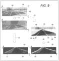
- the additional parallax voting unit votes a parallax that is weighted based on a texture area. Because of this, in the UD voting space, a part corresponding to a boundary between segmented texture areas is emphasized (see FIG. 9 , which will be described later).
- the additional parallax voting unit 500 votes an additional parallax weighted, with respect to an object with a small height, such as a road edge with no level difference. This allows the object detection unit 600 to detect the road edge with no level difference.
- the additional parallax voting unit 500 interpolates a parallax with respect to an area where a parallax image is missing a parallax to make detecting the parallax image as one object difficult. This allows the object detection unit 600 to detect an object missing a parallax.
- An example of an internal configuration of the additional parallax voting unit 500 is shown in FIG. 8 , which will be described later.
- the object detection unit detects an object, based on the number of parallax votes given in the UD voting space, thereby recognizing the external environment.
- the object detection unit 600 is thus able to determine whether the detected object is an obstacle that the host vehicle should avoid.
- An original image as external environment information carries images of various objects, among which an object against which the host vehicle needs to make some control actions, such as an evasive or stopping action, is referred to as an "obstacle ".
- the object detection unit 600 certainly detects even an obstacle with a low height, which is advantageous in comparison with a conventional external environment recognition device.
- Information on an obstacle detected by the object detection unit 600 (the size, distance, type, etc., of the obstacle) is sent to an autonomous driving control unit (ECU), which is not illustrated, and is used for autonomous driving.
- ECU autonomous driving control unit
- the alarm control unit 700 controls various alarms, based on information on an obstacle detected by the object detection unit 600.
- the alarm control unit 700 for example, outputs an instruction to turn a steering wheel in the direction of avoiding an obstacle or apply a brake, to the autonomous driving control unit (not illustrated), causes an instrument panel in the vehicle to display an alarm message, or causes a speaker in the vehicle to emit an alarm sound.
- FIG. 2 is a block diagram showing an example of a hardware configuration of the computer 800.
- the computer 800 is an example of a piece of hardware serving as a computer capable of operating as the external environment recognition device 1 according to this embodiment.
- the external environment recognition device 1, i.e., the computer 800 (computer) of this embodiment executes a program, thereby implementing an image recognition method, which is executed by the functional blocks shown in FIG. 1 that work together to execute the method.
- the computer 800 includes a central processing unit (CPU) 810, a read only memory (ROM) 820, and a random access memory (RAM) 830, which are each connected to a bus 840.
- the computer 800 further includes a nonvolatile storage 850 and a network interface 860.
- the CPU 810 reads the programming code of software for implementing functions of this embodiment, from the ROM 820, loads the programming code onto the RAM 830, and executes the programming code. Variables, parameters, etc., produced during arithmetic processing by the CPU 810 are temporarily written to the RAM 830, from which the CPU 810 reads out these variables, parameters, etc.
- a micro processing unit (MPU) may be used in place of the CPU 810 or the CPU 810 and a graphics processing unit (GPU) may be used together.
- the CPU 810 implements the functions of the external environment information acquisition unit 100, the parallax generation unit 200, the parallax voting unit 300, the texture area segmentation unit 400, the additional parallax voting unit 500, the object detection unit 600, and the alarm control unit 700 that are shown in FIG. 1 .
- nonvolatile storage 850 for example, a hard disk drive (HDD), a solid state drive (SSD), a flexible disk, an optical disk, a magneto-optical disk, a CD-ROM, a CD-R, a magnetic tape, or a nonvolatile memory is used.
- HDD hard disk drive
- SSD solid state drive
- a flexible disk an optical disk
- a magneto-optical disk a CD-ROM
- CD-R compact flash memory
- magnetic tape or a nonvolatile memory
- nonvolatile memory for example, a hard disk drive (HDD), a solid state drive (SSD), a flexible disk, an optical disk, a magneto-optical disk, a CD-ROM, a CD-R, a magnetic tape, or a nonvolatile memory is used.
- OS operating system
- programs by which the computer 800 functions are recorded in the nonvolatile storage 850.
- the ROM 820 and the nonvolatile storage 850 store therein programs, data,
- External environment information acquired by the external environment information acquisition unit 100, a parallax generated by the parallax generation unit 200, the number of parallax votes given in the UD voting space, information on an object detected by the object detection unit 600, and the like are stored in the nonvolatile storage 850, and are collected, when necessary, by a software program developer via a network.
- FIG. 3 depicts an example of a distance frequency distribution in an area (road surface) where no three-dimensional object is present.
- the parallax image 10 on the left side in FIG. 3 shows three-dimensional objects determined from external environment information.
- a range of the parallax image 10 corresponds to an imaging range of a camera 110 (e.g., a stereo camera) shown on the right side of FIG. 3 .
- the horizontal axis of the parallax image 10 indicates the lateral position of the original image on the camera screen, and the vertical axis of the parallax image 10 indicates a distance to (parallax value of) an object appearing on the original image, the distance being determined from a parallax.
- the parallax image 10 Because of this, on the parallax image 10, an object with a short distance to the camera appears on this side (lower side) as an object with a long distance to the camera appears on the far side (upper side). Because the parallax image 10 includes distance information, it is referred to also as a distance image.
- the road surface of a roadway appears in a road surface area 11 on the right side in the parallax image 10.
- the road surface which extends uniformly from an area close to the vehicle to an area distant to the vehicle, is an object with less unevenness.
- description will be made with focus placed on a range of a column 12 in the road surface area 11 on the right side in the parallax image 10.
- the column 12 is made up of 11 blocks whose distances to the camera 110 shown on the right side of FIG. 3 are calculated. 1 block represents a unit number of vote "1".
- a histogram 14 on the upper right side in FIG. 3 shows a voting result of parallax voting made with respect to the distance from the position of the camera 110 to an object, the voting result being indicated within the range of the column 12.
- the parallax voting unit 300 votes the number of blocks with respect to the distance of a block which is, in the road surface area 11, at the same vertical position as any one of blocks arranged in the vertical direction in the column 12. In this manner, a histogram on any given vertical position is created.
- the number of blocks the parallax voting unit 300 votes is a value related to the distance, and the distance is calculated from a parallax. For this reason, in the following description, voting a block of which the distance is equal to a certain distance is referred to also as “parallax voting " or" voting a parallax ".
- the histogram 14 shows a threshold representing the number of votes that should be interpreted as an obstacle.
- the threshold is at the position of 5 blocks. Because the road surface has less unevenness as described above, the number of blocks voted with respect to the road surface is around 1 or 2, regardless of the distance from the road surface to the camera 110. In this case, therefore, the number of blocks is smaller than the threshold "5". Thus, the road surface is not recognized as an obstacle.
- FIG. 4 depicts an example of a distance frequency distribution in an area where a three-dimensional object (preceding vehicle) is present.
- a parallax image 10 shown on the left side in FIG. 4 is identical with the parallax image 10 shown in FIG. 3 .
- a preceding vehicle 18 traveling 10 m ahead of the host vehicle is shown (see the lower right side in FIG. 4 ).
- description is made with focus placed on a range of a column 17 in the vehicle area 16 on the left side in the parallax image 10.
- the column 17 is made up of 11 blocks whose distances to the camera 110 shown on the right side in FIG. 4 are calculated.
- FIG. 4 On the right side in FIG. 4 , a state in which the camera 110 takes an image of the vehicle area 16 in the range of the column 17 is depicted.
- an image of the back of the preceding vehicle 18 is captured at a position of 10 m distant from the camera.
- a histogram 19 on the upper right side in FIG. 4 shows a voting result of parallax voting made with respect to the distance from the position of the camera 110 to an object, the voting result being indicated within the range of the column 17.
- the parallax voting unit 300 votes the number of blocks with respect to the distance of a block which is, in the vehicle area 16, at the same vertical position as any one of blocks arranged in the vertical direction in the column 17.
- blocks are stacked high at the position of about 10 m distant at which the image of the back of the preceding vehicle 18 is captured.
- the number of blocks "6" which is greater than the threshold "5" , is voted at a position of 10 m, i.e., the position of 10 m distant, in the histogram 19. It is thus found, based on the histogram 19, that the back of the preceding vehicle 18 is 10 m ahead of the host vehicle.
- the number of blocks shown in the histograms 14 and 19 differs between an area where a three-dimensional object is not present and an area where a three-dimensional object is present.
- the number of blocks increases according to the height of the three-dimensional object.
- an object the host vehicle should avoid is present as an obstacle.
- a large object like the preceding vehicle 18 shown in FIG. 4 is easily detected as a three-dimensional object.
- a boundary with little height such as a road edge with no level difference
- the number of blocks stacked in the histogram is so small as to be smaller than the threshold, so that recognizing such a boundary is difficult. It is therefore considered to be necessary for autonomous driving that an object difficult to recognize only by the process of voting a block equal in distance to the camera 110 with a block of the column (e.g., a road edge with no level difference, a road edge with a low level difference, a pylon lying on a roadway, and the like.) can be detected.
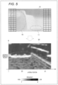
- the UD voting space is a space in which, as indicated by the columns 12 and 17 of the parallax image, the number of parallax votes given with respect to the entire parallax image is reflected by shifting the columns, and the horizontal axis represents the lateral position of the original image on the camera screen as the vertical axis represents a parallax value of (distance to) an object.
- FIG. 5 depicts an example of the parallax image 10 and the UD voting space 20.
- the parallax image 10 of FIGS. 3 and 4 is shown.
- the parallax image 10 shows the road surface area 11 where the road surface is present and the vehicle area 16 where the preceding vehicle is present.
- the UD voting space 20 showing the features of the three-dimensional object is shown.
- the horizontal axis of the UD voting space 20 represents a horizontal position U associated with the horizontal position of parallax image 10, and the vertical axis of the same represents the distance to (parallax value D of) the three-dimensional object.
- the UD voting space 20 is a diagram in which the number of blocks (frequency) voted for each block's distance with respect to the entire parallax image 10 by the method indicated in FGS. 3 and 4 is visualized.
- the frequency i.e., the number of blocks shown as a legend under the UD voting space 20 is obtained as a value ranging from "0" to "7" that corresponds to a frequency shown in the histograms 14 and 19 of FIGS. 3 and 4 .
- a dark color part of the UD voting space 20 indicates a part with a low frequency, and a light color part of the same indicates a part with a high frequency.
- a part with a frequency ranging from "0" to "1” is displayed as a dark color (black) part
- a part raging from "6" to "7” is displayed as a light color (white) part.
- Parallax voting the external environment recognition device 1 of this embodiment performs to detect a three-dimensional object in an improved manner will be described.
- FIG. 6 depicts an example of an original image 30 captured by a stereo camera and a UD voting space 35.
- the original image 30 shown in FIG. 6 is an image captured by a left stereo camera.
- the original image 30 depicting two preceding vehicles 31 and 32 is shown.
- the preceding vehicle 31 is traveling on the same lane where the host vehicle is traveling, and the preceding vehicle 32 is on its way to come out of an adjacent lane and enter the lane where the host vehicle is traveling.
- a median strip 33 is present on the right side to the lane where the host vehicle is traveling.
- the UD voting space 35 is generated based on the original image 30.
- the UD voting space 35 is generated based on a parallax generated from two original images 30.
- the horizontal axis of the UD voting space 35 is defined as a horizontal position U associated with horizontal coordinates in the original image 30, and the vertical axis of the same is defined as a parallax value D representing a distance to an object detected from the original image 30.
- An object in the UD voting space 35 has its position specified by UD coordinates.
- the UD voting space has one axis representing a depth distance in the external environment, and another axis representing an angle at which the external environment information acquisition unit (external environment information acquisition unit 100) can acquire external environment information or a lateral position of an image in a case of external environment information indicating the image.
- the angle at which external environment information can be acquired is equivalent to, for example, an image-capturing angle of the stereo camera in the horizontal direction or a measurement angle of the LiDAR in the horizontal direction, the measurement angle allowing the LiDAR to make measurement.
- a large parallax value D means that a distance in the depth direction (depth distance) to an object appearing in the original image 30 is small, that is, the object is close to the stereo camera (host vehicle) in the depth direction.
- a small parallax value D means that a distance in the depth direction (depth distance) to an object appearing in the original image 30 is large, that is, the object is distant from the stereo camera (host vehicle) in the depth direction.
- a parallax is voted on the assumption that the whole of the back of the preceding vehicle 31 is at the same distance (e.g., 20 m) to the host vehicle.
- the preceding vehicle 32 shows its diagonal view in the original image 30. For this reason, the distance between the back and the right side of the preceding vehicle 32 is detected.
- parallaxes voted with respect to the right side of the preceding vehicle 32 are also accumulated at a position further distanced in the depth direction by the length of the preceding vehicle 32.
- the back and the right side of the preceding vehicle 32 are expressed as a horizontal white line and a diagonal white line, respectively, in the UD voting space 35. As shown in FIG.
- the white line representing the preceding vehicle 32 is thinner (whiter) than the white line representing the preceding vehicle 31.
- This voting result is a simple diagram created in association with the UD voting space 35.
- the number of parallax votes given with respect to the preceding vehicle 32 is "7" at the position of 10 m
- the number of parallax votes given with respect to the preceding vehicle 31 is "6" at the position of 20 m. Because, in the original image 30, the height H2 of the preceding vehicle 32 is higher than the height H1 of the preceding vehicle 31, the number of votes with respect to the preceding vehicle 32 is greater.
- the number of parallax votes given at the position corresponding to the median strip 33 is "1" or "2" in the UD voting space 35. It should be noted that the number of votes in the UD voting space 35 is recorded in a different cell as well, but description of such a cell is skipped because it leads to complicated drawings. As indicated in FIGS. 3 and 4 , the threshold for recognizing an object as an obstacle is "5". The median strip 33 is, therefore, not recognized as an obstacle, in which case a method of increasing the number of votes given with respect to the median strip 33 is required.
- FIG. 7 is a block diagram showing an example of the internal configuration of the texture area segmentation unit 400.
- the texture area segmentation unit includes a locally similar texture area segmentation unit (locally similar texture area segmentation unit 410) that segments external environment information into texture areas for individual textures locally similar to each other, a semantic area segmentation unit (semantic area segmentation unit 420) that segments external environment information into semantic areas for individual object types, and an individual object area segmentation unit (individual object area segmentation unit 430) that segments external environment information into individual object areas for individual objects.
- the locally similar texture area segmentation unit 410 segments an area in the captured original image for individual textures locally similar to each other. It is required that similar textures be at least part of the same object. For example, in an assumed case where one preceding vehicle is present and similar textures (e.g., the same color) exists in that preceding vehicle, an area in the preceding vehicle is segmented for individual similar textures.
- the semantic area segmentation unit 420 segments various objects appearing in a captured original image, as individual semantic areas for objects, such as a vehicle area and a road surface area.
- An area segmented as each semantic area for an object in such a manner is referred to as a "semantic area”.
- semantic segmentation As a method of semantic area segmentation, for example, a segmentation method called semantic segmentation is used.
- Semantic segmentation is a method of attaching a specific label to every pixel in an image and segmenting an area in the image for individual object types. Segmented areas resulting from semantic segmentation are shown as, for example, a semantic area segmentation image 45 of FIG. 9 , which will be described later.
- semantic segmentation when a plurality of vehicles are superimposed in the original image, the whole of those vehicles are segmented as a semantic area, from the original image. In other words, in the semantic area, the plurality of vehicles overlapping in the original image are not segmented into each single vehicle.
- a specific example of a process by the semantic area segmentation unit 420 will be described as a semantic area segmentation process, which will be described later.
- the individual object area segmentation unit 430 segments areas for individual objects, such as a vehicle and a road surface, from a captured original image.
- a segmentation method called instance segmentation is used as a method of individual object area segmentation.
- Instance segmentation is a method of separately detecting a group of objects overlapping in an image and segmenting an area in the image for individual groups of objects detected. Segmented areas resulting from instance segmentation are shown in, for example, an individual object area segmentation image 70A of FIG. 13 , which will be described later.
- An area including an object individually segmented from the image in such a manner is referred to as an "individual object area”.
- a specific example of a process by the individual object area segmentation unit 430 will be described as an individual object area segmentation process, which will be described later.
- FIG. 8 is a block diagram showing an example of the internal configuration of the additional parallax voting unit 500.
- the additional parallax voting unit 500 includes a no-level-difference road edge additional voting unit 510, a road surface paint reduction unit 520, an obstacle type interpolation voting unit 530, an individual obstacle interpolation voting unit 540, and a local area interpolation voting unit 550.
- the no-level-difference road edge additional voting unit 510 performs additional parallax voting with respect to a road edge with no level difference or a low level difference (which is referred to as a "no-level-difference road edge").
- the number of parallax votes given with respect to the no-level-difference road edge is so small that the number of parallax votes is lower than the threshold.
- the no-level-difference road edge additional voting unit 510 adds a parallax to the no-level-difference road edge, thus increasing the number of parallax votes given with respect to the no-level-difference road edge.
- This process allows the object detection unit 600 to detect the no-level-difference road edge as an obstacle. Details of the process by the no-level-difference road edge additional voting unit 510 will be described with reference to FIGS. 9 and 10 , which will be described later.
- the additional parallax voting unit includes the reduction unit (road surface paint reduction unit 520) that reduces the number of parallax votes given with respect to a road sign.
- a road sign painted on the road surface which is referred to as "road surface paint”
- road surface paint such as a zebra zone, a crosswalk, or a stop sign
- the road sign being an example of a specific texture area
- a parallax may develop at a boundary between the road surface and a white line despite the fact that the road surface paint has no height as an object. In this case, the road surface paint is likely to be misinterpreted as the presence of an obstacle.
- the road surface paint reduction unit 520 performs weighting of reducing the number of parallax votes given by the parallax voting unit 300 with respect to the road surface paint.
- the road surface paint reduction unit 520 adjusts the number of parallax votes given by the parallax voting unit 300, with respect to the area to which the label of the road surface paint is attached.
- the road surface paint reduction unit 520 reduces a voting value for the road surface paint, the voting value being the number of parallax votes given by the parallax voting unit 300 with respect to the road surface paint, to the half. It is assumed that the parallax voting unit 300 usually gives a parallax vote in a unit of "1" in the UD voting space.
- the road surface paint reduction unit 520 performs weighting of reducing the number of parallax votes given already, for example, in a unit of "0.5".
- the road surface paint reduction unit 520 may cancel the number of parallax votes given by the parallax voting unit 300 with respect to the segmented area to which the label of the road surface paint is attached, by weighting of adding "-1" vote to the number of parallax votes given already. In this manner, to prevent the object detection unit 600 from wrongly detecting the segmented area to which the label of the road surface paint is attached to be an obstacle, the road surface paint reduction unit 520 makes adjustment to avoid concentration of votes with respect to the segmented area. As a result, when the additional parallax voting unit 500 makes additional voting, the number of votes given with respect to the area to which the label of the road surface paint is attached is adjusted.
- a smoothing filter may be applied to the vicinity of the area of the road surface paint to reduce the number of votes (height) given with respect to the vicinity of the area.
- the road surface paint reduction unit 520 may carry out the process of reducing the number of votes also on a road sign projected on a road surface not painted. In this manner, assuming that the road surface paint constitutes a flat surface creates an effect that the voting value for the painted part is distributed to the voting value for the peripheral area of the painted part, which reduces a possibility of wrongly determining the painted part to be an obstacle. Thus, the object detection unit 600 does not wrongly detect the road surface paint to be an obstacle.
- the obstacle type interpolation voting unit 530 determines whether voting made is voting for a plurality of blocks with the same distance to the camera that make up a column in the image, as shown in FIGS. 3 and 4 . If it is voting for the blocks with the same distance to the camera that make up the column, an object detected has a certain height at that distance. If it is not voting for the blocks with the same distance to the camera that make up the column, the object detected has a low height. Because of such a process, the object detection unit 600 does not wrongly detect the road surface paint, such as a white line, to be an obstacle, and is able to detect a group of objects with a height, such as pedestrians and vehicles, to be obstacles.
- the individual obstacle interpolation voting unit 540 makes voting for interpolating individual types of obstacles. For example, when a plurality of objects appear in the captured original image, the individual obstacle interpolation voting unit 540 separately interpolates individual objects with parallaxes. For example, different pieces of identification information (identification IDs) are assigned respectively to three-dimensional objects, such as vehicles and pedestrians, detected by the individual object area segmentation unit 430. When a plurality of pedestrians crossing a crosswalk are detected, the individual obstacle interpolation voting unit 540 can interpolate a parallax on the assumption that these pedestrians are collectively present at the same distance.
- identification IDs identification information
- the individual obstacle interpolation voting unit 540 can interpolate a parallax on the assumption that these pedestrians are collectively present at the same distance.
- one of two images captured by the stereo cameras (e.g., a right image captured by the right camera) is shown as an original image 40.
- the original image 40 is expressed by a UV coordinates system having the horizontal axis representing a horizontal position U and the vertical axis representing a vertical position V.
- a horizontal line 41 traversing inside the original image 40 is provided to distinguish an image processing target, and is, actually, not shown in the original image 40. Because an area below the horizontal line 41 includes information necessary for traveling of the vehicle, obstacle detection is carried out in the area below the horizontal line 41.
- the numbers of parallax votes given in the UD voting space 50 are shown. In this case, attention is paid to the number of parallax votes given with respect to the boundary between the roadway and the sidewalk in the UD voting space 50, the boundary having its edge emphasized in the parallax image 43.
- the voting result shown on the upper side in FIG. 10 indicates that the number of parallax votes given with respect to the boundary between the roadway and the sidewalk ranges from "2" to "4", which are smaller than the threshold "5".
- the object detection unit 600 shown in FIG. 1 is, therefore, not able to correctly recognize the boundary.
- the no-level-difference road edge additional voting unit 510 of the additional parallax voting unit 500 carries out the voting process for each of the distances of detected objects, thereby generating a UD voting space 55.
- the no-level-difference road edge additional voting unit 510 makes additional voting with respect to the boundary between the roadway and the sidewalk, the boundary being the no-level-difference road edge, based on the semantic area segmentation image 45 generated by the semantic area segmentation unit 420.
- the UD voting space 55 is expressed as the UD coordinates system.
- FIG. 12 depicts an example of respective voting results on images.
- the voting process is carried out in the UD voting space 65, based on the parallax image 60, the number of votes with respect to the area 61, where a parallax is missing, becomes smaller than the threshold, as indicated in an area 66.
- the number of votes becoming smaller than the threshold raises a possibility that the object detection unit 600 wrongly detects one vehicle to be a plurality of different objects.
- the numbers of parallax votes given in the UD voting space 65 are shown.
- the voting result shown on the upper side in FIG. 12 indicates that the number of votes "6" larger than the threshold "5" is given with respect to the boundary between the roadway and the sidewalk, and therefore the object detection unit 600 shown in FIG. 1 can correctly recognize the boundary.
- the object detection unit 600 cannot correctly recognize the size and width of the vehicle or the presence of the vehicle in the traveling direction.
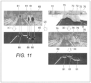
- a semantic area segmentation image 70 that the semantic area segmentation unit 420 shown in FIG. 7 creates by performing semantic area segmentation for each pixel in the original image is considered.
- On an upper right part of FIG. 11 an example of the semantic area segmentation image 70 is shown.
- the semantic area segmentation image 70 individual areas created by performing semantic area segmentation on the original image are shown.
- the semantic area segmentation image 70 is created by segmenting the original image into an area 71 indicating a road surface, an area 72 indicating an object other than the road surface and a vehicle, and an area 73 indicating a vehicle.
- four vehicles shown in the original image are collectively represented by the area 73 indicating a vehicle as one object type.
- Object types that is, the areas 71 to 73 are given different colors, respectively, to distinguish the areas 71 to 73 from each other. When the colored areas 71 to 73 are not distinguished by color differences, they are collectively referred to as a "colored area".
- a process of acquiring the parallax image 60, a process of interpolating a parallax in the parallax image 60, and a process of voting in the UD voting space, based on the interpolated parallax image 60 will then be described separately.
- the obstacle type interpolation voting unit 530 acquires the parallax image 60 from the parallax generation unit 200 (see FIG. 1 ), and interpolates a parallax in the area 61 where a parallax is lost in the parallax image 60.
- the obstacle type interpolation voting unit 530 then interpolates a parallax with respect to each type of object detected in the parallax image 60.
- the obstacle detected in the parallax image 60 is a plane equal in depth in the height direction (vertical direction in the image)
- the obstacle type interpolation voting unit 530 interpolates a parallax missing part with a parallax near the obstacle.
- the obstacle type interpolation voting unit 530 of the additional parallax voting unit interpolates a parallax missing part present in a part corresponding to a texture area in the parallax image having one axis representing the depth distance, with a parallax present in the direction of the axis representing the depth distance of the parallax image.
- the obstacle type interpolation voting unit 530 then votes an additional parallax with respect to each texture area where a parallax missing part is interpolated.
- the obstacle type interpolation voting unit 530 selects a parallax to be interpolated for each attribute in a semantic area.
- the obstacle type interpolation voting unit 530 interpolates a parallax missing part of an object whose attribute in a semantic area is a vehicle, a person, and the like, with a parallax present in the vertical direction, i.e., the direction of the depth distance axis of the parallax image.
- the obstacle type interpolation voting unit 530 interpolates a parallax missing part of an object like a flat plane whose attribute in a semantic area is a road surface or the like, with a parallax present in the horizontal direction, i.e., the direction of the other axis of the parallax image having the depth distance axis.
- a parallax missing part is interpolated with a parallax corresponding to an object type.
- the interpolated parallax is less likely to fluctuate than a parallax present nearby.
- the obstacle type interpolation voting unit 530 of the additional parallax voting unit interpolates a parallax missing part present in a part corresponding to a texture area in the parallax image having one axis representing the depth distance, with a parallax around the parallax missing part, the parallax being present in the same object in which the parallax missing part is present.
- the obstacle type interpolation voting unit 530 then votes an additional parallax with respect to each texture area where a parallax missing part is interpolated. For example, the parallax missing part is interpolated, using pixel values of eight pixels on the upper, lower, left, and right sides surrounding the parallax missing part. As a result, the parallax missing part does not take a parallax value extremely different from that of the surrounding pixels.
- the individual obstacle interpolation voting unit 540 shown in FIG. 8 separately interpolates a parallax in an object with a parallax missing part among objects detected in the parallax image 60.
- the individual obstacle interpolation voting unit 540 interpolates a parallax in the same obstacle (object) among obstacles detected in the parallax image 60.
- a parallax may be interpolated by a method of interpolating a parallax of an area around the area where the parallax is lost or a method of interpolating a parallax of a parallax-including area present above or below the area where the parallax is lost.
- semantic area segmentation unit 420 carries out a wrong semantic area segmentation process will then be described. It is assumed that a result of semantic area segmentation indicates, for example, a result of semantic segmentation of an area including not only an object, which is an obstacle in its original form, but also a road surface in the background of the object, as a large obstacle. In this case of semantic area segmentation, the original image is segmented into an area large than the obstacle in its original form.
- the additional parallax voting unit 500 shown in FIG. 8 checks a parallax voting result on the segmented area, and a parallax exactly needed is added to the obstacle. This allows the object detection unit 600 to accurately detect the width, shape, and position of the obstacle.
- an amount of error between a point group on an object is small even if the object has a curved surface because the plane and the object are the same element.
- the local area interpolation voting unit 550 finds that the possibility of an object (plane) specified in the local area being an obstacle is low. In this case, the local area interpolation voting unit 550 does not use the plane given by the approximation for parallax voting. In addition, in a case where the object is blended with the background and dispersion is observed in the depth direction, this object is identified as an object significantly elongated in the depth direction from this side to the far side, despite the fact that it is a separate object different from the background.
- Texture areas segmented from the original image by the locally similar texture area segmentation unit 410 may be segmented at different places even if they are included in the same object. Similarly, even if individual object areas segmented from the original image by the individual object area segmentation unit 430 are at different places, these individual object areas may be included the same object. For example, in the preceding vehicle 18, the same texture is segmented into segmented areas 120 and 130, as texture areas or individual object areas. This brings a concern that a wrong parallax is voted under the assumption that the segmented areas 120 and 130 are objects different from each other.
- the additional parallax voting unit can confirm from a three-dimensional point group distribution that a plurality of texture areas or individual object areas are included in the same object (preceding vehicle 18)
- the additional parallax voting unit votes a valid parallax in the UD voting space, as a parallax of the same object (preceding vehicle 18).
- the local area interpolation voting unit 550 or the individual obstacle interpolation voting unit 540 confirms a three-dimensional point group distribution with respect to the segmented areas 120 and 130, and checks whether the segmented areas 120 and 130 are included in the same preceding vehicle 18.
- the local area interpolation voting unit 550 or the individual obstacle interpolation voting unit 540 votes a valid parallax in the UD voting space, considering the segmented areas 120 and 130 to be objects different from each other.
- the individual obstacle interpolation voting unit 540 can confirm that in addition to the object, the background is also included in the individual object area. In this case, the individual obstacle interpolation voting unit 540 gives instructions on result confirmation and re-segmentation to the individual object area segmentation unit 430, and acquires a re-segmented object area. The individual obstacle interpolation voting unit 540 then interpolates a parallax in the re-segmented individual object area.
- FIG. 17 is a flowchart showing an example of a process carried out by the external environment recognition device 1. In this flowchart, processes executed by individual units will be described, using the functional block diagram shown in FIG. 1 .
- the external environment information acquisition unit 100 acquires external environment information from a stereo camera or the like (S1). Subsequently, the parallax generation unit 200 generates a parallax from the external environment information (S2). Subsequently, the parallax voting unit 300 votes the parallax in a UD voting space (S3).
- the texture area segmentation unit 400 segments an original image into texture areas, based on the external environment information (S4).
- This process by the texture area segmentation unit 400 may be executed in parallel with the processes of steps S2 and S3 after the external environment information is acquired at step S1.
- the alarm control unit 700 performs alarm control (S7).
- This alarm control allows the host vehicle to avoid an obstacle or stop in front of the obstacle.
- no alarm control is performed.
- the external environment recognition device 1 repeatedly executes these series of steps at given time intervals, with step S1 first.
- an object type tag is added to a result of area segmentation.
- This method may involve a case where because an object as a segmented area is larger than the original object or area segmentation is performed as a part of the original object is unknown, a wrong result is obtained. In such a case, there is a concern that a vehicle may be stopped suddenly or continues to travel by recognizing an obstacle to avoid as an object that does not obstruct the traveling of the vehicle.
- the process of additional parallax voting is additionally performed by the additional parallax voting unit 500 before the object detection unit 600 detects an object.
- the shape of the object is accurately detected and analyzed by the object detection unit 600. Then, based on a result of this object detection, autonomous driving control of the vehicle is performed.
- the method of this embodiment therefore, eliminates the case of the vehicle's suddenly stopping right in front of the obstacle.
- the method of this embodiment eliminates also the case where the vehicle continues to travel by wrongly recognizing an obstacle to avoid as an object that does not obstruct the traveling of the vehicle.
Landscapes
- Engineering & Computer Science (AREA)
- Physics & Mathematics (AREA)
- General Physics & Mathematics (AREA)
- Multimedia (AREA)
- Theoretical Computer Science (AREA)
- Traffic Control Systems (AREA)
- Image Analysis (AREA)
- Image Processing (AREA)
Abstract
a texture area segmentation unit that segments external environment information into a plurality of texture areas for individual textures specified from the external environment information acquired from an external environment information acquisition unit; a parallax generation unit that generates a parallax according to a depth distance of an external environment, based on the external environment information; a parallax voting unit that votes a parallax according to a depth distance of an object, the depth distance being specified from the external environment information, in a voting space having one axis representing the depth distance of the external environment; an additional parallax voting unit that votes an additional parallax in the voting space in which the parallax has been voted, the additional parallax being voted based on a texture area; and an object detection unit that detects the object, based on the number of parallax votes given in the voting space, thereby recognizing the external environment.
Description
- The present invention relates to an external environment recognition device and an external environment recognition method.
- In realization of autonomous driving and an advanced driver assistance system, the importance of an external environment recognition device is increasing, which external environment recognition device monitors an external environment of a vehicle, detects an obstacle on a traveling path and an object necessary for traveling of the vehicle, such a lane on the traveling route, thus recognizing the external environment. To improve object detection performance, according to this external environment recognition device, a vehicle is equipped with a plurality of cameras (stereo cameras), and information on the surroundings of the vehicle is obtained through each camera by photographing. The external environment recognition device thus offers a function of recognizing a situation around the vehicle.
- Stereo cameras used by the external environment recognition device are incorporated in the vehicle such that two stereo cameras are arranged at a given interval in the horizontal direction. The external environment recognition device measures the distance from the camera to an object photographed, using a parallax of an overlapping area of images captured by the two cameras, thereby determining a possibility of coming in contact with the object present in the direction of traveling of the vehicle. However, various objects are present in the external environment, and the vehicle needs a lot of information for its autonomous driving. Thus, a technique that allows the vehicle to correctly recognize the external environment is in great demand.
-
PTL 1 includes this description: "Further, the calculation unit performs object detection, based on visual information, and the control unit controls a moving body so that a detected object appears at a given position in the visual information. Further, the holding unit holds an object model for object detection and holds a target positional orientation relative to the object as well, the target positional orientation indicating the positional orientation that should be taken relative to the object when the AGV arrives at the destination". - PTL 1:
JP 2019-125345 A - It can be assumed that a parallax image formed by a parallax obtained from two images is composed of a three-dimensional point group. A conventional external environment recognition device has difficulty in obtaining objects having no difference or a small difference in height with each other in spite of being different objects, from a parallax image. For example, if a level difference at a boundary between a roadway and a sidewalk or a median strip is low, the conventional external environment recognition device hardly detects a parallax at the boundary and is therefore not able to correctly detect the boundary from a parallax image. Similarly, in the case of an object of uniform texture (e.g., a black car), an object photographed at night, and the like, the conventional external environment recognition device has difficulty in detecting a parallax of such an object and, in many cases, finds a difference between the object and its background to be unclear, thus not being able to correctly detect the object. Even in the case of an object with a pattern in texture, the conventional external environment recognition device cannot detect such an object if its height is low.
- According to the technique disclosed in
Patent Literature 1, a specific object model needs to be held in advance, and an object cannot be correctly detect in an environment where various objects not defined by the object model, such as an outdoor roadway, are present. In addition, in the case of a road boundary with a small level difference or an object with a little texture difference (a black vehicle or the like), detecting such a road boundary or object is more difficult and therefore the technique disclosed inPatent Literature 1 cannot be applied to a control system for autonomous driving. - The present invention has been conceived in view of the above circumstances, and an object of the present invention is to enable detection of various objects that are difficult to detect by using only the information obtained from a parallax.
- An external environment recognition device according to the present invention includes: a texture area segmentation unit that segments external environment information into a plurality of texture areas for individual textures specified from the external environment information acquired from an external environment information acquisition unit; a parallax generation unit that generates a parallax according to a depth distance of an external environment, based on the external environment information; a parallax voting unit that votes a parallax according to a depth distance of an object, the depth distance being specified from the external environment information, in a voting space having one axis representing the depth distance of the external environment; an additional parallax voting unit that votes an additional parallax in the voting space in which the parallax has been voted, the additional parallax being added based on a texture area; and an object detection unit that detects the object, based on the number of parallax votes given in the voting space, thereby recognizing the external environment.
- According to the present invention, the additional parallax added based on the texture area is voted in the voting space in which the parallax is voted. This allows correct detection of an object.
-
- [
FIG. 1] FIG. 1 is a block diagram showing an example of an internal configuration of an external environment recognition device according to one embodiment of the present invention. - [
FIG. 2] FIG. 2 is a block diagram showing an example of a hardware configuration of a computer according to the one embodiment of the present invention. - [
FIG. 3] FIG. 3 depicts an example of a distance frequency distribution in an area (road surface) where no three-dimensional object is present, according to the one embodiment of the present invention. - [
FIG. 4] FIG. 4 depicts an example of a distance frequency distribution in an area where a three-dimensional object (preceding vehicle) is present, according to the one embodiment of the present invention. - [
FIG. 5] FIG. 5 depicts an example of a parallax image and a UD voting space according to the one embodiment of the present invention. - [
FIG. 6] FIG. 6 depicts an example of an original image captured by a stereo camera and a UD voting space according to the one embodiment of the present invention. - [
FIG. 7] FIG. 7 is a block diagram showing an example of an internal configuration of a texture area segmentation unit according to the one embodiment of the present invention. - [
FIG. 8] FIG. 8 is a block diagram showing an example of an internal configuration of an additional parallax voting unit according to the one embodiment of the present invention. - [
FIG. 9] FIG. 9 depicts transition of individual images for description of semantic area segmentation according to the one embodiment of the present invention. - [
FIG. 10] FIG. 10 depicts an example of voting results on individual images according to the one embodiment of the present invention. - [
FIG. 11] FIG. 11 depicts an example in which obstacle interpolation voting is made after semantic area segmentation is performed, according to the one embodiment of the present invention. - [
FIG. 12] FIG. 12 depicts an example of respective voting results on images according to the one embodiment of the present invention. - [
FIG. 13] FIG. 13 depicts an example in which obstacle interpolation voting is performed after individual object area segmentation is made, according to the one embodiment of the present invention. - [
FIG. 14] FIG. 14 is a diagram for explaining a process of recognizing a pylon, according to the one embodiment of the present invention. - [
FIG. 15] FIG. 15 is a diagram for explaining a process on a plurality of texture areas included in the same object, according to the one embodiment of the present invention. - [
FIG. 16] FIG. 16 is a diagram for explaining a process of confirming an individual object area having a size within a specified range, according to the one embodiment of the present invention. - [
FIG. 17] FIG. 17 is a flowchart showing an example of a process carried out by the external environment recognition device according to the one embodiment of the present invention. - Embodiments of the present invention will hereinafter be described with reference to the accompanying drawings. In the present specification and drawings, constituent elements substantially identical in function or configuration are denoted by the identical reference signs to spare redundant description.
- An example of an internal configuration of an external
environment recognition device 1 according to one embodiment of the present invention will first be described with reference toFIG. 1 . -
FIG. 1 is a block diagram showing an example of the internal configuration of the externalenvironment recognition device 1. The externalenvironment recognition device 1 is a part of an electronic control unit (ECU) incorporated in a vehicle, and is a device that recognizes an object in the external environment, based on external environment information acquired in the direction of traveling of the vehicle. The vehicle having the externalenvironment recognition device 1 incorporated therein is referred to as "host vehicle ". The present invention is applicable to, for example, an advanced driver assistance system (ADAS) or to an arithmetic device for vehicle control with which or an in-vehicle electronic control unit (ECU) for autonomous driving (AD) can communicate. - The external
environment recognition device 1 includes an external environmentinformation acquisition unit 100, aparallax generation unit 200, aparallax voting unit 300, a texturearea segmentation unit 400, an additionalparallax voting unit 500, anobject detection unit 600, and analarm control unit 700. - The external environment information acquisition unit (external environment information acquisition unit 100) acquires information detected by a sensing device and information detected by a different sensing device, as external environment information. The sensing device and the different sensing devices are set in the direction of traveling of the vehicle (that is, set on a front part and a rear part of the vehicle).
- A configuration is assumed, in which the sensing device is a first camera and the different sensing device is a second camera set in the horizontal direction of the first camera. In this case, the first camera and second camera are used as stereo cameras, and the external environment information acquisition unit (external environment information acquisition unit 100) acquires external environment images captured by the first camera and second camera, as external environment information. Another configuration may also be assumed, in which the sensing device is a monocular camera and the different sensing device is a measuring device (Light Detection and Ranging (LiDAR), millimeter wave radar, infrared sensor, and the like) that measures a distance to an object, based on a distribution of a group of three-dimensional points, the distribution being obtained by emitting an electromagnetic wave (laser beam, millimeter wave, infrared rays, and the like) onto the object. In this case, the external environment information acquisition unit (external environment information acquisition unit 100) acquires an external environment image captured by the monocular camera and a distribution of a group of three-dimensional points, the distribution being outputted from the measuring device, as external environment information.
- The parallax generation unit (parallax generation unit 200) generates a parallax according to the depth distance of the external environment, based on external environment information inputted from the external environment
information acquisition unit 100. For example, theparallax generation unit 200 carries out pattern matching between two images simultaneously captured by the stereo cameras to generate a parallax of any given object in the images. A parallax generated by theparallax generation unit 200 is exemplarily shown as aparallax image 10 inFIGS. 3 and4 , which will be referred to later. Theparallax image 10 includes distance information indicating a relative distance from the stereo camera to the object in a depth direction. In the following description, the relative distance from the stereo camera to the object in the depth direction, the relative distance being indicated theparallax image 10, is referred to as a "distance". - The parallax voting unit (parallax voting unit 300) votes a parallax according to the depth distance of an object, the depth distance being specified from external environment information, in a UD voting space having one axis representing the depth distance of the external environment. The
parallax voting unit 300 thus determines the distance from the vehicle to the object, based on a parallax inputted from theparallax generation unit 200, and votes the parallax in the UD voting space according to the determined distance. The UD voting space is a space having the horizontal axis defining a horizontal position U in terms of image coordinates and the vertical axis defining a parallax value D. The parallax value D represents a depth distance. For example, when external environment information indicates that a different vehicle is present 20 m ahead of the vehicle in its direction of traveling, an image indicating the presence of the different vehicle is displayed in a parallax image. The details of the UD voting space will be described later with reference toFIGS. 3 to 6 . - The texture area segmentation unit (texture area segmentation unit 400) segments external environment information into a plurality of texture areas for individual textures specified from the external environment information acquired from the external environment information acquisition unit (external environment information acquisition unit 100). For example, the texture
area segmentation unit 400 segments external environment information for individual objects of the same texture, such as roadways, sidewalks, lanes, and vehicles, among various objects indicated in the external environment information. Texture refers to such properties of an object as a surface shape, a pattern, and a color. According to this definition, vehicles or lanes that are the same in object type but are different in texture may be segmented into different texture areas. An example of an internal configuration of the texturearea segmentation unit 400 is shown inFIG. 7 , which will be described later. - The additional parallax voting unit (additional parallax voting unit 500) votes an additional parallax in the UD voting space, where a parallax has been voted by the
parallax voting unit 300, based on segmented texture areas created by the texturearea segmentation unit 400. The additional parallax voting unit (additional parallax voting unit 500) votes a parallax that is weighted based on a texture area. Because of this, in the UD voting space, a part corresponding to a boundary between segmented texture areas is emphasized (seeFIG. 9 , which will be described later). For example, the additionalparallax voting unit 500 votes an additional parallax weighted, with respect to an object with a small height, such as a road edge with no level difference. This allows theobject detection unit 600 to detect the road edge with no level difference. - In addition, the additional
parallax voting unit 500 interpolates a parallax with respect to an area where a parallax image is missing a parallax to make detecting the parallax image as one object difficult. This allows theobject detection unit 600 to detect an object missing a parallax. An example of an internal configuration of the additionalparallax voting unit 500 is shown inFIG. 8 , which will be described later. - The object detection unit (object detection unit 600) detects an object, based on the number of parallax votes given in the UD voting space, thereby recognizing the external environment. The
object detection unit 600 is thus able to determine whether the detected object is an obstacle that the host vehicle should avoid. An original image as external environment information carries images of various objects, among which an object against which the host vehicle needs to make some control actions, such as an evasive or stopping action, is referred to as an "obstacle ". Theobject detection unit 600 certainly detects even an obstacle with a low height, which is advantageous in comparison with a conventional external environment recognition device. Information on an obstacle detected by the object detection unit 600 (the size, distance, type, etc., of the obstacle) is sent to an autonomous driving control unit (ECU), which is not illustrated, and is used for autonomous driving. - The
alarm control unit 700 controls various alarms, based on information on an obstacle detected by theobject detection unit 600. Thealarm control unit 700, for example, outputs an instruction to turn a steering wheel in the direction of avoiding an obstacle or apply a brake, to the autonomous driving control unit (not illustrated), causes an instrument panel in the vehicle to display an alarm message, or causes a speaker in the vehicle to emit an alarm sound. - A hardware configuration of a
computer 800 making up the externalenvironment recognition device 1 will then be described. -
FIG. 2 is a block diagram showing an example of a hardware configuration of thecomputer 800. Thecomputer 800 is an example of a piece of hardware serving as a computer capable of operating as the externalenvironment recognition device 1 according to this embodiment. The externalenvironment recognition device 1, i.e., the computer 800 (computer) of this embodiment executes a program, thereby implementing an image recognition method, which is executed by the functional blocks shown inFIG. 1 that work together to execute the method. - The
computer 800 includes a central processing unit (CPU) 810, a read only memory (ROM) 820, and a random access memory (RAM) 830, which are each connected to abus 840. Thecomputer 800 further includes anonvolatile storage 850 and anetwork interface 860. - The
CPU 810 reads the programming code of software for implementing functions of this embodiment, from theROM 820, loads the programming code onto theRAM 830, and executes the programming code. Variables, parameters, etc., produced during arithmetic processing by theCPU 810 are temporarily written to theRAM 830, from which theCPU 810 reads out these variables, parameters, etc. A micro processing unit (MPU) may be used in place of theCPU 810 or theCPU 810 and a graphics processing unit (GPU) may be used together. TheCPU 810 implements the functions of the external environmentinformation acquisition unit 100, theparallax generation unit 200, theparallax voting unit 300, the texturearea segmentation unit 400, the additionalparallax voting unit 500, theobject detection unit 600, and thealarm control unit 700 that are shown inFIG. 1 . - As the
nonvolatile storage 850, for example, a hard disk drive (HDD), a solid state drive (SSD), a flexible disk, an optical disk, a magneto-optical disk, a CD-ROM, a CD-R, a magnetic tape, or a nonvolatile memory is used. As well as an operating system (OS) and various parameters, programs by which thecomputer 800 functions are recorded in thenonvolatile storage 850. TheROM 820 and thenonvolatile storage 850 store therein programs, data, and the like theCPU 810 needs for its operation, and are used as an example of a computer-readable non-transitory storage medium storing programs executed by thecomputer 800. External environment information acquired by the external environmentinformation acquisition unit 100, a parallax generated by theparallax generation unit 200, the number of parallax votes given in the UD voting space, information on an object detected by theobject detection unit 600, and the like are stored in thenonvolatile storage 850, and are collected, when necessary, by a software program developer via a network. - For example, a network interface card (NIC) or the like is used as the
network interface 860, and various data can be transmitted and received between devices via a local area network (LAN), a dedicated line, or the like that is connected to a terminal of the NIC. The externalenvironment recognition device 1 can transmit and receive various data to and from an external cloud server or the like through thenetwork interface 860. - Before description of an example of internal configurations of the texture
area segmentation unit 400 and the additionalparallax voting unit 500 shown inFIG. 1 , a parallax voting process and the UD voting space will be described with reference toFIGS. 3 to 6 . A process of determining a distance frequency for each pixel of theparallax image 10 including distance information determined from a parallax of an object will be described. -
FIG. 3 depicts an example of a distance frequency distribution in an area (road surface) where no three-dimensional object is present. - The
parallax image 10 on the left side inFIG. 3 shows three-dimensional objects determined from external environment information. A range of theparallax image 10 corresponds to an imaging range of a camera 110 (e.g., a stereo camera) shown on the right side ofFIG. 3 . The horizontal axis of theparallax image 10 indicates the lateral position of the original image on the camera screen, and the vertical axis of theparallax image 10 indicates a distance to (parallax value of) an object appearing on the original image, the distance being determined from a parallax. Because of this, on theparallax image 10, an object with a short distance to the camera appears on this side (lower side) as an object with a long distance to the camera appears on the far side (upper side). Because theparallax image 10 includes distance information, it is referred to also as a distance image. - The road surface of a roadway appears in a
road surface area 11 on the right side in theparallax image 10. The road surface, which extends uniformly from an area close to the vehicle to an area distant to the vehicle, is an object with less unevenness. InFIG. 3 , description will be made with focus placed on a range of acolumn 12 in theroad surface area 11 on the right side in theparallax image 10. Thecolumn 12 is made up of 11 blocks whose distances to thecamera 110 shown on the right side ofFIG. 3 are calculated. 1 block represents a unit number of vote "1". - On the right side in
FIG. 3 , a state in which thecamera 110 takes an image of theroad surface area 11 in the range of thecolumn 12 is depicted. In animaging range 13 of thecamera 110 shown inFIG. 3 , only the image of the road surface is captured. Ahistogram 14 on the upper right side inFIG. 3 shows a voting result of parallax voting made with respect to the distance from the position of thecamera 110 to an object, the voting result being indicated within the range of thecolumn 12. Theparallax voting unit 300 votes the number of blocks with respect to the distance of a block which is, in theroad surface area 11, at the same vertical position as any one of blocks arranged in the vertical direction in thecolumn 12. In this manner, a histogram on any given vertical position is created. The number of blocks theparallax voting unit 300 votes is a value related to the distance, and the distance is calculated from a parallax. For this reason, in the following description, voting a block of which the distance is equal to a certain distance is referred to also as "parallax voting " or" voting a parallax ". - The
histogram 14 shows a threshold representing the number of votes that should be interpreted as an obstacle. The threshold is at the position of 5 blocks. Because the road surface has less unevenness as described above, the number of blocks voted with respect to the road surface is around 1 or 2, regardless of the distance from the road surface to thecamera 110. In this case, therefore, the number of blocks is smaller than the threshold "5". Thus, the road surface is not recognized as an obstacle. -
FIG. 4 depicts an example of a distance frequency distribution in an area where a three-dimensional object (preceding vehicle) is present. - A
parallax image 10 shown on the left side inFIG. 4 is identical with theparallax image 10 shown inFIG. 3 . In avehicle area 16 on the left side in theparallax image 10, a precedingvehicle 18 traveling 10 m ahead of the host vehicle is shown (see the lower right side inFIG. 4 ). InFIG. 4 , description is made with focus placed on a range of acolumn 17 in thevehicle area 16 on the left side in theparallax image 10. Thecolumn 17 is made up of 11 blocks whose distances to thecamera 110 shown on the right side inFIG. 4 are calculated. - On the right side in
FIG. 4 , a state in which thecamera 110 takes an image of thevehicle area 16 in the range of thecolumn 17 is depicted. In theimaging range 13 of thecamera 110 shown inFIG. 4 , an image of the back of the precedingvehicle 18 is captured at a position of 10 m distant from the camera. Ahistogram 19 on the upper right side inFIG. 4 shows a voting result of parallax voting made with respect to the distance from the position of thecamera 110 to an object, the voting result being indicated within the range of thecolumn 17. Theparallax voting unit 300 votes the number of blocks with respect to the distance of a block which is, in thevehicle area 16, at the same vertical position as any one of blocks arranged in the vertical direction in thecolumn 17. - As shown on the left side in
FIG. 4 , blocks are stacked high at the position of about 10 m distant at which the image of the back of the precedingvehicle 18 is captured. As a result, the number of blocks "6", which is greater than the threshold "5", is voted at a position of 10 m, i.e., the position of 10 m distant, in thehistogram 19. It is thus found, based on thehistogram 19, that the back of the precedingvehicle 18 is 10 m ahead of the host vehicle. - In this manner, the number of blocks shown in the
histograms - A large object like the preceding
vehicle 18 shown inFIG. 4 is easily detected as a three-dimensional object. In the case of a boundary with little height, such as a road edge with no level difference, however, the number of blocks stacked in the histogram is so small as to be smaller than the threshold, so that recognizing such a boundary is difficult. It is therefore considered to be necessary for autonomous driving that an object difficult to recognize only by the process of voting a block equal in distance to thecamera 110 with a block of the column (e.g., a road edge with no level difference, a road edge with a low level difference, a pylon lying on a roadway, and the like.) can be detected. - It should be noted that a result of parallax voting made with respect to each distance of an object, the parallax voting being depicted in
FIGS. 3 and4 , that is, the number of parallax votes given according to the distance of the object is reflected in the UD voting space, which will be described later. The UD voting space is a space in which, as indicated by thecolumns -
FIG. 5 depicts an example of theparallax image 10 and theUD voting space 20. - On the upper side in
FIG. 5 , theparallax image 10 ofFIGS. 3 and4 is shown. Theparallax image 10 shows theroad surface area 11 where the road surface is present and thevehicle area 16 where the preceding vehicle is present. - On the lower side in
FIG. 5 , theUD voting space 20 showing the features of the three-dimensional object is shown. The horizontal axis of theUD voting space 20 represents a horizontal position U associated with the horizontal position ofparallax image 10, and the vertical axis of the same represents the distance to (parallax value D of) the three-dimensional object. TheUD voting space 20 is a diagram in which the number of blocks (frequency) voted for each block's distance with respect to theentire parallax image 10 by the method indicated in FGS. 3 and 4 is visualized. The frequency, i.e., the number of blocks shown as a legend under theUD voting space 20 is obtained as a value ranging from "0" to "7" that corresponds to a frequency shown in thehistograms FIGS. 3 and4 . A dark color part of theUD voting space 20 indicates a part with a low frequency, and a light color part of the same indicates a part with a high frequency. For example, in theUD voting space 20, a part with a frequency ranging from "0" to "1" is displayed as a dark color (black) part, while a part raging from "6" to "7" is displayed as a light color (white) part. - In this process of coloring in accordance with the frequency of a block voted with respect to a certain vertical position (distance) in the
parallax image 10, the vertical position in theparallax image 10 is changed. As a result, theUD voting space 20 is generated. In theUD voting space 20 shown inFIG. 5 , anarea 21 on the lower right side indicates the presence of a road edge with no level difference, and anarea 22 on the upper left side indicates the presence of the precedingvehicle 18. In this manner, by using theUD voting space 20 colored in accordance with the frequencies of blocks, an object with a sufficient height is easily detected but an object with a small height is still difficult to detect. For example, the road edge with no level difference shown in thearea 21 of theUD voting space 20 has the boundary that makes the sidewalk slightly higher than the roadway, and therefore the frequency of blocks for the road edge is higher than the frequency of blocks for the road surface. However, because the height of the boundary is smaller than the height of the back of the precedingvehicle 18, the frequency of blocks for the road edge for each distance is low as a whole. - Parallax voting the external
environment recognition device 1 of this embodiment performs to detect a three-dimensional object in an improved manner will be described. -
FIG. 6 depicts an example of anoriginal image 30 captured by a stereo camera and aUD voting space 35. Theoriginal image 30 shown inFIG. 6 is an image captured by a left stereo camera. - On an upper part of
FIG. 6 , theoriginal image 30 depicting two precedingvehicles 31 and 32 is shown. The precedingvehicle 31 is traveling on the same lane where the host vehicle is traveling, and the preceding vehicle 32 is on its way to come out of an adjacent lane and enter the lane where the host vehicle is traveling. Amedian strip 33 is present on the right side to the lane where the host vehicle is traveling. - Under the
original image 30 ofFIG. 6 , an example of theUD voting space 35 is shown, theUD voting space 35 being generated based on theoriginal image 30. TheUD voting space 35 is generated based on a parallax generated from twooriginal images 30. The horizontal axis of theUD voting space 35 is defined as a horizontal position U associated with horizontal coordinates in theoriginal image 30, and the vertical axis of the same is defined as a parallax value D representing a distance to an object detected from theoriginal image 30. An object in theUD voting space 35 has its position specified by UD coordinates. In this manner, the UD voting space has one axis representing a depth distance in the external environment, and another axis representing an angle at which the external environment information acquisition unit (external environment information acquisition unit 100) can acquire external environment information or a lateral position of an image in a case of external environment information indicating the image. The angle at which external environment information can be acquired is equivalent to, for example, an image-capturing angle of the stereo camera in the horizontal direction or a measurement angle of the LiDAR in the horizontal direction, the measurement angle allowing the LiDAR to make measurement. - A large parallax value D means that a distance in the depth direction (depth distance) to an object appearing in the
original image 30 is small, that is, the object is close to the stereo camera (host vehicle) in the depth direction. Conversely, a small parallax value D means that a distance in the depth direction (depth distance) to an object appearing in theoriginal image 30 is large, that is, the object is distant from the stereo camera (host vehicle) in the depth direction. As indicated inFIG. 5 , in theUD voting space 35, a result of voting made with respect to a parallax point group generated according to distances to objects is indicated. - In the
UD voting space 35, a parallax is voted on the assumption that the whole of the back of the precedingvehicle 31 is at the same distance (e.g., 20 m) to the host vehicle. As a result, parallaxes voted with respect to the precedingvehicle 31 are accumulated at a position of the parallax value D=20 m, at which a white horizontal line is displayed in line with the lateral width of the precedingvehicle 31. Meanwhile, the preceding vehicle 32 shows its diagonal view in theoriginal image 30. For this reason, the distance between the back and the right side of the preceding vehicle 32 is detected. As a result, in theUD voting space 35, parallaxes voted with respect to the back of the preceding vehicle 32 are accumulated at a position of the parallax value D=10 m. In addition, parallaxes voted with respect to the right side of the preceding vehicle 32 are also accumulated at a position further distanced in the depth direction by the length of the preceding vehicle 32. The back and the right side of the preceding vehicle 32 are expressed as a horizontal white line and a diagonal white line, respectively, in theUD voting space 35. As shown inFIG. 6 , because the height H2 of the preceding vehicle 32 close to the host vehicle is larger in the vertical direction than the height H1 of the precedingvehicle 31 more distant from the host vehicle, the white line representing the preceding vehicle 32 is thinner (whiter) than the white line representing the precedingvehicle 31. - On a lower part of
FIG. 6 , an example of a voting result is shown. This voting result is a simple diagram created in association with theUD voting space 35. As shown in the voting result, the number of parallax votes given with respect to the preceding vehicle 32 is "7" at the position of 10 m, and the number of parallax votes given with respect to the precedingvehicle 31 is "6" at the position of 20 m. Because, in theoriginal image 30, the height H2 of the preceding vehicle 32 is higher than the height H1 of the precedingvehicle 31, the number of votes with respect to the preceding vehicle 32 is greater. - Because the height H3 of the
median strip 33 shown on the right side in theoriginal image 30 is small, the number of parallax votes given at the position corresponding to themedian strip 33 is "1" or "2" in theUD voting space 35. It should be noted that the number of votes in theUD voting space 35 is recorded in a different cell as well, but description of such a cell is skipped because it leads to complicated drawings. As indicated inFIGS. 3 and4 , the threshold for recognizing an object as an obstacle is "5". Themedian strip 33 is, therefore, not recognized as an obstacle, in which case a method of increasing the number of votes given with respect to themedian strip 33 is required. - An example of an internal configuration of the texture
area segmentation unit 400 will then be described. -
FIG. 7 is a block diagram showing an example of the internal configuration of the texturearea segmentation unit 400. - The texture area segmentation unit (texture area segmentation unit 400) includes a locally similar texture area segmentation unit (locally similar texture area segmentation unit 410) that segments external environment information into texture areas for individual textures locally similar to each other, a semantic area segmentation unit (semantic area segmentation unit 420) that segments external environment information into semantic areas for individual object types, and an individual object area segmentation unit (individual object area segmentation unit 430) that segments external environment information into individual object areas for individual objects.
- The locally similar texture
area segmentation unit 410 segments an area in the captured original image for individual textures locally similar to each other. It is required that similar textures be at least part of the same object. For example, in an assumed case where one preceding vehicle is present and similar textures (e.g., the same color) exists in that preceding vehicle, an area in the preceding vehicle is segmented for individual similar textures. - The semantic
area segmentation unit 420 segments various objects appearing in a captured original image, as individual semantic areas for objects, such as a vehicle area and a road surface area. An area segmented as each semantic area for an object in such a manner is referred to as a "semantic area". As a method of semantic area segmentation, for example, a segmentation method called semantic segmentation is used. Semantic segmentation is a method of attaching a specific label to every pixel in an image and segmenting an area in the image for individual object types. Segmented areas resulting from semantic segmentation are shown as, for example, a semanticarea segmentation image 45 ofFIG. 9 , which will be described later. According to semantic segmentation, when a plurality of vehicles are superimposed in the original image, the whole of those vehicles are segmented as a semantic area, from the original image. In other words, in the semantic area, the plurality of vehicles overlapping in the original image are not segmented into each single vehicle. A specific example of a process by the semanticarea segmentation unit 420 will be described as a semantic area segmentation process, which will be described later. - The individual object
area segmentation unit 430 segments areas for individual objects, such as a vehicle and a road surface, from a captured original image. As a method of individual object area segmentation, for example, a segmentation method called instance segmentation is used. Instance segmentation is a method of separately detecting a group of objects overlapping in an image and segmenting an area in the image for individual groups of objects detected. Segmented areas resulting from instance segmentation are shown in, for example, an individual objectarea segmentation image 70A ofFIG. 13 , which will be described later. An area including an object individually segmented from the image in such a manner is referred to as an "individual object area". A specific example of a process by the individual objectarea segmentation unit 430 will be described as an individual object area segmentation process, which will be described later. - In the following description, when the texture area, the semantic area, and the individual object area are not distinguished from each other, they may be collectively referred to as "segmented area".
- An example of an internal configuration of the additional
parallax voting unit 500 will then be described. -
FIG. 8 is a block diagram showing an example of the internal configuration of the additionalparallax voting unit 500. - The additional
parallax voting unit 500 includes a no-level-difference road edgeadditional voting unit 510, a road surfacepaint reduction unit 520, an obstacle typeinterpolation voting unit 530, an individual obstacleinterpolation voting unit 540, and a local areainterpolation voting unit 550. - In the UD voting space, the no-level-difference road edge
additional voting unit 510 performs additional parallax voting with respect to a road edge with no level difference or a low level difference (which is referred to as a "no-level-difference road edge"). The number of parallax votes given with respect to the no-level-difference road edge is so small that the number of parallax votes is lower than the threshold. The no-level-difference road edgeadditional voting unit 510 adds a parallax to the no-level-difference road edge, thus increasing the number of parallax votes given with respect to the no-level-difference road edge. This process allows theobject detection unit 600 to detect the no-level-difference road edge as an obstacle. Details of the process by the no-level-difference road edgeadditional voting unit 510 will be described with reference toFIGS. 9 and10 , which will be described later. - The additional parallax voting unit (additional parallax voting unit 500) includes the reduction unit (road surface paint reduction unit 520) that reduces the number of parallax votes given with respect to a road sign. For example, when a road sign painted on the road surface (which is referred to as "road surface paint"), such as a zebra zone, a crosswalk, or a stop sign, the road sign being an example of a specific texture area, is a road surface paint extending in the depth direction, a parallax may develop at a boundary between the road surface and a white line despite the fact that the road surface paint has no height as an object. In this case, the road surface paint is likely to be misinterpreted as the presence of an obstacle. In another case, if a white line is painted in such a way as to cross a lane, no parallax develops and therefore a distance to the white line becomes unclear. However, the process by the semantic
area segmentation unit 420 according to this embodiment makes it clear that such a white line is a painted part on the road surface. The road surfacepaint reduction unit 520 performs weighting of reducing the number of parallax votes given by theparallax voting unit 300 with respect to the road surface paint. When the texturearea segmentation unit 400 segments an area to which a label of the road surface paint is attached, the road surfacepaint reduction unit 520 adjusts the number of parallax votes given by theparallax voting unit 300, with respect to the area to which the label of the road surface paint is attached. - For example, the road surface
paint reduction unit 520 reduces a voting value for the road surface paint, the voting value being the number of parallax votes given by theparallax voting unit 300 with respect to the road surface paint, to the half. It is assumed that theparallax voting unit 300 usually gives a parallax vote in a unit of "1" in the UD voting space. The road surfacepaint reduction unit 520 performs weighting of reducing the number of parallax votes given already, for example, in a unit of "0.5". The road surfacepaint reduction unit 520 may cancel the number of parallax votes given by theparallax voting unit 300 with respect to the segmented area to which the label of the road surface paint is attached, by weighting of adding "-1" vote to the number of parallax votes given already. In this manner, to prevent theobject detection unit 600 from wrongly detecting the segmented area to which the label of the road surface paint is attached to be an obstacle, the road surfacepaint reduction unit 520 makes adjustment to avoid concentration of votes with respect to the segmented area. As a result, when the additionalparallax voting unit 500 makes additional voting, the number of votes given with respect to the area to which the label of the road surface paint is attached is adjusted. - The road surface
paint reduction unit 520 may adjust the number of votes (height) given with respect to a specific part in the UD voting space after additional voting is over. A case is assumed, for example, where it is found from a parallax value that the road surface paint is at a position of U=100 and D=10 in the UD voting space. In this case, the road surfacepaint reduction unit 520 reduces the number of votes (height) given with respect to a voting space near the area of the road surface paint, to the half. In addition, to ensure that a voting value representing the number of parallax votes given with respect to the road surface paint is not significantly different from a voting value for a peripheral area of the painted part, a smoothing filter may be applied to the vicinity of the area of the road surface paint to reduce the number of votes (height) given with respect to the vicinity of the area. In addition, the road surfacepaint reduction unit 520 may carry out the process of reducing the number of votes also on a road sign projected on a road surface not painted. In this manner, assuming that the road surface paint constitutes a flat surface creates an effect that the voting value for the painted part is distributed to the voting value for the peripheral area of the painted part, which reduces a possibility of wrongly determining the painted part to be an obstacle. Thus, theobject detection unit 600 does not wrongly detect the road surface paint to be an obstacle. - The obstacle type
interpolation voting unit 530 makes voting for interpolating an obstacle type. For example, when a plurality of objects appear in the original image, if the objects are of the same type, the obstacle typeinterpolation voting unit 530 interpolates an obstacle type with respect to the entire group of the objects, regardless of the positions of the objects. Objects are classified into different types of objects, such as vehicles, pedestrians, roads, white lines, and road surface paints. It is required that such objects as a vehicle and a pedestrian be detected certainly as obstacles. These objects are thus interpolated with parallaxes for individual object types to prevent a failure in detection of the objects. The obstacle typeinterpolation voting unit 530 determines whether voting made is voting for a plurality of blocks with the same distance to the camera that make up a column in the image, as shown inFIGS. 3 and4 . If it is voting for the blocks with the same distance to the camera that make up the column, an object detected has a certain height at that distance. If it is not voting for the blocks with the same distance to the camera that make up the column, the object detected has a low height. Because of such a process, theobject detection unit 600 does not wrongly detect the road surface paint, such as a white line, to be an obstacle, and is able to detect a group of objects with a height, such as pedestrians and vehicles, to be obstacles. - The individual obstacle
interpolation voting unit 540 makes voting for interpolating individual types of obstacles. For example, when a plurality of objects appear in the captured original image, the individual obstacleinterpolation voting unit 540 separately interpolates individual objects with parallaxes. For example, different pieces of identification information (identification IDs) are assigned respectively to three-dimensional objects, such as vehicles and pedestrians, detected by the individual objectarea segmentation unit 430. When a plurality of pedestrians crossing a crosswalk are detected, the individual obstacleinterpolation voting unit 540 can interpolate a parallax on the assumption that these pedestrians are collectively present at the same distance. In the case of preceding vehicles, if the preceding vehicles are present in the same object, a parallax can be interpolated on the assumption that preceding vehicles are present at the same distance. Because of such a process, theobject detection unit 600 can separately detect a high object as an obstacle or collectively detect a plurality of objects as obstacles. - The local area
interpolation voting unit 550 makes voting for interpolating a local similar texture area segmented by the locally similar texturearea segmentation unit 410. The local similar texture area is referred to also as a "local area". In the original image, the same texture in the same object is segmented as a local area. The local areainterpolation voting unit 550 votes a parallax on the assumption that all objects, distances, or planes are the same if they are present in the same local area similar texture. If parallaxes are widely dispersed, on the other hand, the local areainterpolation voting unit 550 may not interpolate a parallax even if objects, distances, or planes are present in the same local area similar texture area. For example, if parallaxes are dispersed at positions of 5 m and 20 m, it can be considered to be a case where textures of different objects happen to be the same, in which case a parallax is not interpolated. Because of such a process, theobject detection unit 600 can detect objects of the same texture that are dispersed in the same object, as a single object. - Semantic area segmentation will then be described with reference to
FIGS. 9 and10 . -
FIG. 9 depicts transition of individual images for description of semantic area segmentation. -
FIG. 10 depicts an example of voting results on individual images. - On the upper side in
FIG. 9 , one of two images captured by the stereo cameras (e.g., a right image captured by the right camera) is shown as anoriginal image 40. Theoriginal image 40 is expressed by a UV coordinates system having the horizontal axis representing a horizontal position U and the vertical axis representing a vertical position V. Ahorizontal line 41 traversing inside theoriginal image 40 is provided to distinguish an image processing target, and is, actually, not shown in theoriginal image 40. Because an area below thehorizontal line 41 includes information necessary for traveling of the vehicle, obstacle detection is carried out in the area below thehorizontal line 41. An area above thehorizontal line 41 include a distant building, a road, an upper part of a tree, or the like, that is, only the objects with which the vehicle by no means comes in contact are shown in the area. Obstacle detection in this area is, therefore, unnecessary. - Processing
areas 42 each framed with a white line are shown in theoriginal image 40. In an assumed case where the host vehicle is traveling straight on the left, the host vehicle needs to keep traveling in the same lane except when making a lane change. Thus, an area including a boundary between a sidewalk and a roadway, the boundary being on the left side of the lane in which the host vehicle is traveling, and an area including an boundary between a sidewalk and a roadway in the opposite lane are selected as theprocessing areas 42, and parallax voting, additional parallax voting, and the like are performed with respect to theprocessing areas 42. The entire area below thehorizontal line 41 may be selected as theprocessing area 42. Details of individual processes will be described, with process numbers (1) to (4) being added to arrows shown inFIG. 9 . - The
parallax generation unit 200 generates a parallax from two images captured by the stereo cameras. Parallaxes generated by theparallax generation unit 200 are shown as aparallax image 43 inFIG. 9 . Theparallax image 43 is expressed by the UV coordinates system as theoriginal image 40 is. In theparallax image 43, an area with a large parallax is displayed on this side, while an area with a small parallax is displayed on the far side. Because a high object, such as a preceding vehicle, a person, or a traffic light, is not shown in theoriginal image 40, theparallax image 43 does not include a parallax of an object that could be an obstacle to the host vehicle. - Based on the
parallax image 43, theparallax voting unit 300 carries out a voting process for the distance of each detected object to generate theUD voting space 50. TheUD voting space 50 is expressed as the UD coordinates system having the horizontal axis U and the vertical axis D (depth (parallax)). In theparallax image 43, as described above, a parallax of an object that could be an obstacle to the host vehicle is not included, and because a level difference at the boundary between the roadway and the sidewalk is small, aboundary 51 is blurred and unclear. If thisparallax image 43 is used for autonomous driving control, the position of the host vehicle in the roadway may become unclear. To prevent this, the semanticarea segmentation unit 420 shown inFIG. 7 performs semantic area segmentation in theoriginal image 40. - On the upper side in
FIG. 10 , the numbers of parallax votes given in theUD voting space 50 are shown. In this case, attention is paid to the number of parallax votes given with respect to the boundary between the roadway and the sidewalk in theUD voting space 50, the boundary having its edge emphasized in theparallax image 43. The voting result shown on the upper side inFIG. 10 indicates that the number of parallax votes given with respect to the boundary between the roadway and the sidewalk ranges from "2" to "4", which are smaller than the threshold "5". Theobject detection unit 600 shown inFIG. 1 is, therefore, not able to correctly recognize the boundary. - The semantic
area segmentation unit 420 performs semantic area segmentation for each pixel in theoriginal image 40. When semantic area segmentation is performed, theoriginal image 40 is turned into a semanticarea segmentation image 45 which is segmented into areas for individual object semantics. The semanticarea segmentation image 45 is created by segmenting theoriginal image 40 into anarea 46 indicating the road surface, anarea 47 indicating white lines demarcating a traveling lane, and anarea 48 including sidewalks other than the roadway (seeFIG. 9 ). It should be noted, however, that because theprocessing area 42 shown in theoriginal image 40 includes respective boundaries of thearea 46 indicating the road surface and thearea 48 including the sidewalk other than the roadway, detecting the boundaries of theareas - In the middle part of
FIG. 10 , parallaxes (numbers of votes) added based on the semanticarea segmentation image 45 are shown. In the semanticarea segmentation image 45, aboundary 49 between the roadway and the sidewalk is shown clearly. A parallax is thus added to theboundary 49. The added parallax may be a uniform value or a different value. It is necessary, however, that a parallax be added so that the number of votes given with respect to the boundary, which is unclear in theUD voting space 50, exceeds the threshold. - The no-level-difference road edge
additional voting unit 510 of the additionalparallax voting unit 500 carries out the voting process for each of the distances of detected objects, thereby generating aUD voting space 55. At this time, the no-level-difference road edgeadditional voting unit 510 makes additional voting with respect to the boundary between the roadway and the sidewalk, the boundary being the no-level-difference road edge, based on the semanticarea segmentation image 45 generated by the semanticarea segmentation unit 420. TheUD voting space 55 is expressed as the UD coordinates system. In theUD voting space 55, as a result of additional parallax voting made based on the semanticarea segmentation image 45, theboundary 56 between the roadway and the sidewalk is shown more clearly (highlighted white) than in theUD voting space 50 generated from theparallax image 43 only. Thisboundary 56 shows a feature of a shoulder with no level difference. As a result, the host vehicle is able to travel while recognizing the roadway inside the shoulder with no level difference. - On the lower side in
FIG. 10 , a voting result of parallax voting in which a parallax is added to theUD voting space 50 is shown. This voting result indicates that the numbers of votes with respect to parts where parallaxes are added are each larger than the threshold value "5". Thus, theobject detection unit 600 shown inFIG. 1 can correctly detect the boundary between the roadway and the sidewalk. The processes indicated inFIGS. 9 and10 may be carried out on a texture area segmented by the locally similar texturearea segmentation unit 410. - A process by which voting is made after parallax interpolation on an obstacle (which is referred to as "obstacle interpolation voting") will then be described with reference to
FIGS. 11 and12 . -
FIG. 11 depicts an example in which obstacle interpolation voting is made after semantic area segmentation is performed. InFIG. 11 , the original image is not shown. -
FIG. 12 depicts an example of respective voting results on images. - On an upper left part of
FIG. 11 , an example of aparallax image 60 is shown. - The
parallax image 60 shows a vehicle traveling in the same direction of traveling of the host vehicle, and a plurality of vehicles traveling in the opposite lane. In this case, if the back of the vehicle traveling in the same direction of traveling of the host vehicle is black or the vehicle is traveling at night, a parallax of the vehicle traveling in the same direction of traveling of the host vehicle may be lost in anarea 61. Similarly, a parallax of the vehicle traveling on the opposite lane may also be lost in thearea 61. In this manner, a parallax of a part supposed to have a parallax is lost. This phenomenon is referred to as "parallax missing". Parallax missing tends to occur at a part where the texture of the original image is weak, e.g., a part where a difference in shading does not exist. - When the voting process is carried out in the
UD voting space 65, based on theparallax image 60, the number of votes with respect to thearea 61, where a parallax is missing, becomes smaller than the threshold, as indicated in anarea 66. The number of votes becoming smaller than the threshold raises a possibility that theobject detection unit 600 wrongly detects one vehicle to be a plurality of different objects. - On the upper side in
FIG. 12 , the numbers of parallax votes given in theUD voting space 65 are shown. In this case, attention is paid to the numbers of parallax votes given with respect to the boundary between the roadway and the sidewalk, the boundary having its edge emphasized in theparallax image 60, and to a face of a vehicle that faces the host vehicle, in theUD voting space 65. The voting result shown on the upper side inFIG. 12 indicates that the number of votes "6" larger than the threshold "5" is given with respect to the boundary between the roadway and the sidewalk, and therefore theobject detection unit 600 shown inFIG. 1 can correctly recognize the boundary. On the other hand, because the face of the vehicle that faces the host vehicle loses a parallax in thearea 61, the number of votes "2" smaller than the threshold "5" is given with respect to the face of the vehicle that faces the host vehicle. As a result, theobject detection unit 600 cannot correctly recognize the size and width of the vehicle or the presence of the vehicle in the traveling direction. - To deal with this problem, a semantic
area segmentation image 70 that the semanticarea segmentation unit 420 shown inFIG. 7 creates by performing semantic area segmentation for each pixel in the original image is considered. On an upper right part ofFIG. 11 , an example of the semanticarea segmentation image 70 is shown. - In the semantic
area segmentation image 70, individual areas created by performing semantic area segmentation on the original image are shown. The semanticarea segmentation image 70 is created by segmenting the original image into anarea 71 indicating a road surface, anarea 72 indicating an object other than the road surface and a vehicle, and anarea 73 indicating a vehicle. According to semantic area segmentation, four vehicles shown in the original image are collectively represented by thearea 73 indicating a vehicle as one object type. Object types, that is, theareas 71 to 73 are given different colors, respectively, to distinguish theareas 71 to 73 from each other. When thecolored areas 71 to 73 are not distinguished by color differences, they are collectively referred to as a "colored area". - A process of acquiring the
parallax image 60, a process of interpolating a parallax in theparallax image 60, and a process of voting in the UD voting space, based on the interpolatedparallax image 60 will then be described separately. - Acquisition of the
parallax image 60 interpolated with a parallax will first be described. The obstacle type interpolation voting unit 530 (seeFIG. 8 ) acquires theparallax image 60 from the parallax generation unit 200 (seeFIG. 1 ), and interpolates a parallax in thearea 61 where a parallax is lost in theparallax image 60. - The obstacle type
interpolation voting unit 530 then interpolates a parallax with respect to each type of object detected in theparallax image 60. In this case, assuming that the obstacle detected in theparallax image 60 is a plane equal in depth in the height direction (vertical direction in the image), the obstacle typeinterpolation voting unit 530 interpolates a parallax missing part with a parallax near the obstacle. - It is assumed that the following methods (a) to (c) are adopted as methods by which the obstacle type
interpolation voting unit 530 interpolates a parallax. - The obstacle type
interpolation voting unit 530 of the additional parallax voting unit (additional parallax voting unit 500) interpolates a parallax missing part present in a part corresponding to a texture area in the parallax image having one axis representing the depth distance, with a parallax present in the direction of the axis representing the depth distance of the parallax image. The obstacle typeinterpolation voting unit 530 then votes an additional parallax with respect to each texture area where a parallax missing part is interpolated. The obstacle typeinterpolation voting unit 530 selects a parallax to be interpolated for each attribute in a semantic area. For example, the obstacle typeinterpolation voting unit 530 interpolates a parallax missing part of an object whose attribute in a semantic area is a vehicle, a person, and the like, with a parallax present in the vertical direction, i.e., the direction of the depth distance axis of the parallax image. On the other hand, the obstacle typeinterpolation voting unit 530 interpolates a parallax missing part of an object like a flat plane whose attribute in a semantic area is a road surface or the like, with a parallax present in the horizontal direction, i.e., the direction of the other axis of the parallax image having the depth distance axis. In this manner, a parallax missing part is interpolated with a parallax corresponding to an object type. As a result, the interpolated parallax is less likely to fluctuate than a parallax present nearby. - The obstacle type
interpolation voting unit 530 of the additional parallax voting unit (additional parallax voting unit 500) interpolates a parallax missing part present in a part corresponding to a texture area in the parallax image having one axis representing the depth distance, with a parallax around the parallax missing part, the parallax being present in the same object in which the parallax missing part is present. The obstacle typeinterpolation voting unit 530 then votes an additional parallax with respect to each texture area where a parallax missing part is interpolated. For example, the parallax missing part is interpolated, using pixel values of eight pixels on the upper, lower, left, and right sides surrounding the parallax missing part. As a result, the parallax missing part does not take a parallax value extremely different from that of the surrounding pixels. - For example, a parallax readily develops at an edge detected on a boundary between a background and an object or between a road surface and an object. However, because the edge has no thickness, the parallax is likely to break. In addition, a parallax readily develops on a part with a texture because in such a part, the same area of left and right images can be identified. However, a parallax hardly develops on a part with no texture because in such a part, the same area of left and right images is difficult to identify. The obstacle type
interpolation voting unit 530 carries out a process of interpolating an area where a parallax is lost, that is, a parallax breaks or hardly develops, with a parallax of a parallax-including area near the above area. Thus, the obstacle typeinterpolation voting unit 530 can obtain a continuous parallax. - Each of the methods (b) and (c), however, raises a concern that a parallax missing part may be interpolated in black areas (where a parallax frequency is small) that are most frequently found in the vertical direction of the parallax image. For this reason, the obstacle type
interpolation voting unit 530 does not treat black as a valid parallax but treats it as an invalid parallax. The obstacle typeinterpolation voting unit 530 then interpolates an invalid parallax part (black area) where a parallax is lost, with a parallax around the invalid parallax part (part different from the black area). - In addition, the obstacle type
interpolation voting unit 530 may interpolate a parallax in a semantic area, the parallax being weighted in proportion to the area of the semantic area. For example, in a case where a plurality of preceding vehicles are present, weighting of a parallax with respect to a preceding vehicle which is close to the host vehicle and whose semantic area has a large area is made greater than weighting of a parallax with respect to a preceding vehicle which is distant from the host vehicle and whose semantic area has a small area. Performing weighting proportional to the area of the semantic area in this manner allows theobject detection unit 600 to reliably detect a preceding vehicle close to the host vehicle. - An image the obstacle type
interpolation voting unit 530 creates by interpolating parallax missing parts with parallaxes is shown in a middle part ofFIG. 11 , as aparallax interpolation image 75. Anarea 78 of theparallax interpolation image 75 is a part where a parallax is interpolated in thearea 61 that is the parallax missing part shown on an upper left part ofFIG. 11 . In theparallax image 60, the process of parallax interpolation or the like is not carried out on a part other than thearea 61. - Parallaxes (the numbers of parallax votes) that are added to the
parallax interpolation image 75, based on the semantic area segmentation image 70 (seeFIG. 11 ) are shown in the middle part ofFIG 12 . In theparallax interpolation image 75, a parallax is interpolated in the area 78 (seeFIG. 11 ). The interpolated parallax may be a uniform value or a different value. It is necessary, however, that a parallax be interpolated so that the number of votes given with respect to thearea 66, which is a parallax missing area in theUD voting space 65, exceeds the threshold. - The obstacle type
interpolation voting unit 530 of the additionalparallax voting unit 500 carries out the voting process for each object type detected from theparallax interpolation image 75, thereby generating aUD voting space 80. TheUD voting space 80 is expressed as a UD coordinates system. The obstacle typeinterpolation voting unit 530 interpolates an additional parallax, which is a parallax added by the obstacle typeinterpolation voting unit 530, in a parallax missing part, which is a part where a parallax is lost in theUD voting space 65. - On the lower side in
FIG. 12 , a voting result obtained by interpolating additional parallaxes in theUD voting space 80 is shown. This voting result demonstrates that the number of parallax votes of each part interpolated with an additional parallax is "6" that is larger than the threshold "5". As a result, theobject detection unit 600 shown inFIG. 1 can correctly recognize the width and size of a vehicle and the presence of the vehicle in thearea 81 inFIG. 11 . The host vehicle is, therefore, able to travel while recognizing the roadway. - According to the conventional process of directly making parallax voting in the UD voting space, based on the
parallax image 60, if a parallax of an object is missing in thearea 66, which is the parallax missing part, it is high possible that the conventional object detection unit fails to detect an obstacle. However, the obstacle typeinterpolation voting unit 530 adds a parallax to the parallax missing part to interpolate the parallax in the UD voting space. This process, compared with the process of voting a parallax in the UD voting space, based on theparallax mage 60, makes it easy for theobject detection unit 600 to detect an object as a single entity in a reliable manner. Hence the possibility of theobject detection unit 600 detecting an obstacle is improved. - A process of adding a parallax to a parallax missing part in an individual object area will then be described.
-
FIG. 13 depicts an example in which obstacle interpolation voting is made after individual object area segmentation is performed. InFIG. 13 , the original image is not shown. Because images inFIG. 11 and images inFIG. 13 are substantially the same, description of detailed processes is partially omitted. - When voting process in the
UD voting space 65 is carried out, based on theparallax image 60, the number of parallax votes given with respect to theparallax missing area 61 becomes smaller than the threshold, as indicated in thearea 66. This raises a possibility that theobject detection unit 600 wrongly detects one vehicle to be a plurality of different objects, which has been described above with reference toFIG. 9 . - A process the individual object
area segmentation unit 430 shown inFIG. 8 carries out to generate an individual objectarea segmentation image 70A from the original image by performing individual object area segmentation for each pixel will be described. On an upper right part ofFIG. 13 , an example of the individual objectarea segmentation image 70A is shown. - In the individual object
area segmentation image 70A, each of individual object areas resulting from individual object area segmentation performed on the original image is shown. The individual objectarea segmentation image 70A is created by segmenting the original image into individual object areas of anarea 71 indicating a road surface, anarea 72 indicating the road surface and an object other than a vehicle, and areas 73a to 73d indicating vehicles. By individual object area segmentation, four vehicles shown in the original image are expressed as individual areas 73a to 73d, respectively. The individual objectarea segmentation unit 430 labels the individual areas 73a to 73d "car 1 " to"car 4 ", respectively. - First, the individual obstacle
interpolation voting unit 540 shown inFIG. 8 separately interpolates a parallax in an object with a parallax missing part among objects detected in theparallax image 60. The individual obstacleinterpolation voting unit 540 interpolates a parallax in the same obstacle (object) among obstacles detected in theparallax image 60. A parallax may be interpolated by a method of interpolating a parallax of an area around the area where the parallax is lost or a method of interpolating a parallax of a parallax-including area present above or below the area where the parallax is lost. In addition, if considering the position of an object is unnecessary, distances to respective parts of the same object may be regarded as the same distance. For example, although a distance from the host vehicle to the front of a vehicle traveling in the opposite lane and a distance from the host vehicle to the side of the same are different from each other, the distance to the side of the vehicle may be taken to be the same as the distance to the front of the same. Then, by the individual objectarea segmentation unit 430, individual distances to objects (obstacles) can be determined even if the objects (obstacles) are located far from the host vehicle. Hence a parallax can be separately interpolated in a parallax missing part of an object. - (3) The process of interpolating an additional parallax in a parallax missing part of the
parallax image 60 and (4) the process of voting a parallax in the UD voting space, the parallax being added to theparallax interpolation image 75, have been described with reference toFIG. 11 . - In this manner, the individual object
area segmentation unit 430 recognizes individual objects appearing in the original image and segments the original image into individual object areas, thus being able to correctly recognize each object. As a result, compared with the process of directly making parallax voting in the UD voting space, based on theparallax image 60, the possibility of separately detecting each object can be improved. - Some of obstacle detection methods will be described.
- According to the object detection method by semantic area segmentation described above, the texture
area segmentation unit 400 performs area segmentation on a part where parallax votes concentrate to mark a voting value equal to or higher than a certain threshold in the UD voting space while connecting pixel values of eight pixels near a pixel of interest in the UD voting space, which are eight pixels located on the upper, lower, left, right, upper right, lower right, upper left, and lower left sides to the pixel of interest at their center. Area segmentation may be performed as pixel values of eight pixels near a pixel of interest in the UD voting space, which are eight pixels located on the upper, lower, left, and right sides to the pixel of interest at their center, are connected. In texture area segmentation on an object, such as a vehicle, the texturearea segmentation unit 400 gives the same ID to the same part with respect to a parallax vote is given. This allows theobject detection unit 600 to detect this part to be a single object. In addition, as a result of addition of a parallax to a parallax missing part, theobject detection unit 600 can make an analysis of a three-dimensional vehicle shape, which analysis is still difficult when individual object area segmentation is solely applied, and can also make an analysis of the lateral position, orientation, and shape of a vehicle. Two examples of a process of preventing theobject detection unit 600 from wrongly detecting an object that could be an obstacle will be described below. - First, a case where the individual object
area segmentation unit 430 carries out a wrong individual object area segmentation process will be described. It is assumed, for example, that the individual objectarea segmentation unit 430 obtains a result of wrong individual object area segmentation, which indicates the presence of an object, such as a road edge or a vehicle, that could be an obstacle on a flat road surface or the like. As described above, the individual obstacleinterpolation voting unit 540 votes a parallax interpolated in the road surface in the UD voting space. In this case, in the UD voting space, parallax votes are distributed in the depth direction of the road surface and consequently a large number of parallax votes are not given with respect to an individual object area wrongly segmented as an object present on the road surface. Therefore, even if the individual objectarea segmentation unit 430 makes an error in individual object area segmentation, producing a wrong detection result is prevented. As a result, an object the host vehicle should avoid on the road surface is correctly detected by theobject detection unit 600. - A case where the semantic
area segmentation unit 420 carries out a wrong semantic area segmentation process will then be described. It is assumed that a result of semantic area segmentation indicates, for example, a result of semantic segmentation of an area including not only an object, which is an obstacle in its original form, but also a road surface in the background of the object, as a large obstacle. In this case of semantic area segmentation, the original image is segmented into an area large than the obstacle in its original form. However, the additionalparallax voting unit 500 shown inFIG. 8 checks a parallax voting result on the segmented area, and a parallax exactly needed is added to the obstacle. This allows theobject detection unit 600 to accurately detect the width, shape, and position of the obstacle. - Both of the wrong
detection preventing processes detection preventing processes object detection unit 600 offers an effect of preventing wrong detection of an obstacle while accurately detecting the three-dimensional shape of an object. - A local area interpolation process will then be described.
-
FIG. 14 is a diagram for explaining a process of recognizing a pylon. On an upper left part ofFIG. 14 ., an example of anoriginal image 90 showing a pylon placed on a road surface is shown. On a lower left part ofFIG. 14 , an example of aparallax image 95 generated from theoriginal image 90 is shown. - On the right side in
FIG. 14 , a diagram of a three-dimensional point group and an estimated plane is shown. As described above, a parallax image is composed of three-dimensional point groups. An object with a curved surface, such as a conical pylon, is blended with its background, and this often makes it difficult for the conventional external environment recognition device to separately recognize the object. The locally similar texturearea segmentation unit 410 shown inFIG. 7 approximates a point group on the same cell acquired by, for example, LiDAR to a plane. The shape of one object, such as a pylon shown on the lower left part ofFIG. 14 , is referred to as a cell. - The local area
interpolation voting unit 550 shown inFIG. 8 determines whether a plane of a local area is a side face of the same three-dimensional object, based on an amount of error between a point group on the plane of the local area, which is segmented by the locally similar texturearea segmentation unit 410, and a point group acquired by LiDAR. For example, in an local area recognized by the locally similar texturearea segmentation unit 410 as an area where a background and an object are blended together, an amount of error between a point group on the background and a point group on the object is large because the background and the object are not the same element. On the other hand, in compared with a large amount of error between a point group on an object (e.g., a side of the pylon) and a point group on the background, the object and the background being not the same element, an amount of error between a point group on a plane of a local area and a point group on an object (e.g., a side of the pylon) is small even if the object has a curved surface because the plane and the object are the same element. - Thus, as indicated on the right side in
FIG. 14 , the local areainterpolation voting unit 550 checks whether the point group of the local area is present in the same depth direction or on the same three-dimensional plane. When determining that one cell is one object, the local areainterpolation voting unit 550 implements depth interpolation in the cell. Thereafter, by using the cell in which depth interpolation is implemented, the local areainterpolation voting unit 550 is able to interpolate a parallax or noise rendered invalid and vote an additional parallax. - However, even when the point group can be approximated to the plane of the local area, if the plane given by the approximation is close to the position and inclination of the road surface, the local area
interpolation voting unit 550 finds that the possibility of an object (plane) specified in the local area being an obstacle is low. In this case, the local areainterpolation voting unit 550 does not use the plane given by the approximation for parallax voting. In addition, in a case where the object is blended with the background and dispersion is observed in the depth direction, this object is identified as an object significantly elongated in the depth direction from this side to the far side, despite the fact that it is a separate object different from the background. In this case, the local areainterpolation voting unit 550 assumes that the locally similar texturearea segmentation unit 410 fails to correctly segment the object. The locally similar texturearea segmentation unit 410 then re-segments the original image. Thereafter, the local areainterpolation voting unit 550 votes a parallax with respect to a local area resulting from the re-segmentation. It should be noted, however, the local areainterpolation voting unit 550 may not vote a parallax with respect to the local area resulting from the re-segmentation. In this case, theobject detection unit 600 detects an object, based on only the number of parallax votes given by theparallax voting unit 300 with respect to the local area resulting from the re-segmentation. - Other examples of using a three-dimensional point group will be described.
-
FIG. 15 is a diagram for explaining a process on a plurality of texture areas included in the same object.FIG. 15 shows an example of the back of the precedingvehicle 18. - Texture areas segmented from the original image by the locally similar texture area segmentation unit 410 (see
FIG. 7 ) may be segmented at different places even if they are included in the same object. Similarly, even if individual object areas segmented from the original image by the individual objectarea segmentation unit 430 are at different places, these individual object areas may be included the same object. For example, in the precedingvehicle 18, the same texture is segmented intosegmented areas segmented areas - Thus, when the additional parallax voting unit (additional parallax voting unit 500) can confirm from a three-dimensional point group distribution that a plurality of texture areas or individual object areas are included in the same object (preceding vehicle 18), the additional parallax voting unit (additional parallax voting unit 500) votes a valid parallax in the UD voting space, as a parallax of the same object (preceding vehicle 18). For example, the local area
interpolation voting unit 550 or the individual obstacleinterpolation voting unit 540 confirms a three-dimensional point group distribution with respect to thesegmented areas segmented areas vehicle 18. When confirming that thesegmented areas vehicle 18, based on the three-dimensional point group distribution, the local areainterpolation voting unit 550 or the individual obstacleinterpolation voting unit 540 votes a valid parallax in the UD voting space, considering thesegmented areas - When confirming that the
segmented areas vehicle 18, the local areainterpolation voting unit 550 or the individual obstacleinterpolation voting unit 540 votes a valid parallax in the UD voting space, considering thesegmented areas - In the above first example of the process using the three-dimensional point group, when the
segmented areas interpolation voting unit 550 may estimate planes or curved surfaces of thesegmented areas object detection unit 600 can correctly detect an object. -
FIG. 16 is a diagram for explaining a process of confirming an individual object area having a size within a specified range.FIG. 16 shows an example of the precedingvehicle 18 traveling diagonally. - It is assumed that the individual object area segmentation unit 430 (see
FIG. 7 ) segments the whole of the precedingvehicle 18 as one object, from the original image into an individual object area and labels the precedingvehicle 18 "car 1". However, if the segmented individual object area includes an object of a wrong size as an individual object, a parallax of this individual object area is not adequate for voting. - For this reason, when the additional parallax voting unit (additional parallax voting unit 500) confirms that the size of the individual object area is present as the size of an individual object (vehicle), based on a three-dimensional point group distribution, the additional parallax voting unit space votes a valid parallax in the UD voting space, as a parallax of the individual object (preceding vehicle 18). For example, when the individual object is a vehicle, it is confirmed whether the size of the vehicle is within the range of the width being 3 m or less and the depth being 10 m or less. When confirming that the size of the vehicle is within the range of the width being 3 m or less and the depth being 10 m or less, the individual obstacle
interpolation voting unit 540 votes a parallax in the UD voting space, considering the individual object area to be one object. By this process, a parallax is voted in the UD voting space, as a parallax of the individual object area having a proper size. - If the size of the individual object is not within the range, the individual obstacle
interpolation voting unit 540 can confirm that in addition to the object, the background is also included in the individual object area. In this case, the individual obstacleinterpolation voting unit 540 gives instructions on result confirmation and re-segmentation to the individual objectarea segmentation unit 430, and acquires a re-segmented object area. The individual obstacleinterpolation voting unit 540 then interpolates a parallax in the re-segmented individual object area. - The range in which the individual obstacle
interpolation voting unit 540 confirms the size of an individual object area is changed for each object type. For example, in the case of an individual object area to which a pedestrian label is attached, whether the size of the individual object area is within the range of the width being 1 m or less and the height being 2 m or less is confirmed. - An example of a process carried out by the external
environment recognition device 1 will then be described. -
FIG. 17 is a flowchart showing an example of a process carried out by the externalenvironment recognition device 1. In this flowchart, processes executed by individual units will be described, using the functional block diagram shown inFIG. 1 . - First, the external environment
information acquisition unit 100 acquires external environment information from a stereo camera or the like (S1). Subsequently, theparallax generation unit 200 generates a parallax from the external environment information (S2). Subsequently, theparallax voting unit 300 votes the parallax in a UD voting space (S3). - Subsequently, the texture
area segmentation unit 400 segments an original image into texture areas, based on the external environment information (S4). This process by the texturearea segmentation unit 400 may be executed in parallel with the processes of steps S2 and S3 after the external environment information is acquired at step S1. - Subsequently, the additional
parallax voting unit 500 votes an additional parallax in the UD voting space in which the parallax has been voted by theparallax voting unit 300, the additional parallax being based on a texture area (S5). Subsequently, theobject detection unit 600 detects an object, based on the parallax voted in the UD voting space (S6). - Then, when the object detected by the
object detection unit 600 is an obstacle, thealarm control unit 700 performs alarm control (S7). This alarm control allows the host vehicle to avoid an obstacle or stop in front of the obstacle. When the object detected by theobject detection unit 600 is not an obstacle, no alarm control is performed. The externalenvironment recognition device 1 repeatedly executes these series of steps at given time intervals, with step S1 first. - According to the external
environment recognition device 1 of one embodiment described above, when the UD voting space is generated from the parallax image, a parallax is voted based on a texture area segmented for each object, which makes recognition of each object clear in the UD voting space. This prevents a failure in detection or wrong detection of an object that is hardly detected by a conventional method, such as a road edge, a black vehicle, or an object with a low height left on the road, thus allowing stable, i.e., robust detection. - According to the conventional method, an object type tag is added to a result of area segmentation. This method may involve a case where because an object as a segmented area is larger than the original object or area segmentation is performed as a part of the original object is unknown, a wrong result is obtained. In such a case, there is a concern that a vehicle may be stopped suddenly or continues to travel by recognizing an obstacle to avoid as an object that does not obstruct the traveling of the vehicle. In contrast, according to the method of this embodiment, the process of additional parallax voting is additionally performed by the additional
parallax voting unit 500 before theobject detection unit 600 detects an object. Thus, after a parallax is voted according to a distance to the object, the shape of the object is accurately detected and analyzed by theobject detection unit 600. Then, based on a result of this object detection, autonomous driving control of the vehicle is performed. The method of this embodiment, therefore, eliminates the case of the vehicle's suddenly stopping right in front of the obstacle. The method of this embodiment eliminates also the case where the vehicle continues to travel by wrongly recognizing an obstacle to avoid as an object that does not obstruct the traveling of the vehicle. - In addition, according to the conventional method, there may be an object that is not detected. According to the method of this embodiment, however, even in a case where an object is not detected by the conventional method, the additional
parallax voting unit 500 interpolates a parallax and makes additional parallax voting with respect to the object. This allows theobject detection unit 600 to correctly detect the object. - It should be noted that the present invention is not limited to the above-described embodiment and that, obviously, the present invention may be implemented as various other applications and modifications, providing that such applications and modifications do not depart from the substance of the present invention described in the claims.
- For example, the above embodiment including its device configurations has been described specifically in detail to give an understandable description of the present invention, and is not necessarily limited to an embodiment including all constituent elements described above. Some of constituent elements of this embodiment can be deleted or added to or replaced with different constituent elements.
- Control lines and information lines considered to be necessary for the description are indicated, and control lines and information lines the product needs are not necessarily indicated entirely. It is safe to consider that actually, almost all constituent elements are interconnected.
-
- 1
- external environment recognition device
- 100
- external environment information acquisition unit
- 110
- camera
- 200
- parallax generation unit
- 300
- parallax voting unit
- 400
- texture area segmentation unit
- 410
- locally similar texture area segmentation unit
- 420
- semantic area segmentation
- 430
- individual object area segmentation unit
- 500
- additional parallax voting unit
- 510
- road edge additional voting unit
- 520
- road surface paint reduction unit
- 530
- obstacle type interpolation voting unit
- 540
- individual obstacle interpolation voting unit
- 550
- local area interpolation voting unit
- 600
- object detection unit
- 700
- alarm control unit
Claims (14)
- An external environment recognition device comprising:a texture area segmentation unit that segments external environment information into a plurality of texture areas for individual textures specified from the external environment information acquired from an external environment information acquisition unit;a parallax generation unit that generates a parallax according to a depth distance of an external environment, based on the external environment information;a parallax voting unit that votes a parallax according to a depth distance of an object, the depth distance being specified from the external environment information, in a voting space having one axis representing the depth distance of the external environment;an additional parallax voting unit that votes an additional parallax in the voting space in which the parallax has been voted, the additional parallax being voted based on a texture area; andan object detection unit that detects the object, based on a number of parallax votes given in the voting space, thereby recognizing the external environment.
- The external environment recognition device according to claim 1, wherein
the additional parallax voting unit adds a parallax that is weighted based on the texture area. - The external environment recognition device according to claim 2, wherein
the additional parallax voting unit interpolates a parallax missing part present in a part corresponding to the texture area of a parallax image having one axis representing the depth distance, with a parallax present in a direction of the axis representing the depth distance of the parallax image, and votes an additional parallax with respect to each texture area where the parallax missing part is interpolated. - The external environment recognition device according to claim 2, wherein
the additional parallax voting unit interpolates a parallax missing part present in a part corresponding to the texture area in the parallax image having one axis representing the depth distance, with a parallax around the parallax missing part, the parallax being present in the same object in which the parallax missing part is present, and votes an additional parallax with respect to each texture area where the parallax missing part is interpolated. - The external environment recognition device according to claim 3, wherein
the texture area segmentation unit includes:a locally similar texture area segmentation unit that segments the external environment information into the texture areas for individual locally similar textures;a semantic area segmentation unit that segments the external environment information into semantic areas for individual object types; andan individual object area segmentation unit that segments the external environment information into individual object areas for individual objects. - The external environment recognition device according to claim 5, wherein
the additional parallax voting unit includes a reduction unit that reduces a number of parallax votes given with respect to a road sign. - The external environment recognition device according to claim 5, wherein
when the additional parallax voting unit confirms from a three-dimensional point group distribution that a plurality of the texture areas or of the individual object areas are included in the same object, the additional parallax voting unit votes a valid parallax in the voting space, as a parallax of the same object. - The external environment recognition device according to claim 5, wherein
when the additional parallax voting unit estimates planes or curved surfaces of the texture areas, and confirms that a plurality of the texture areas are included in the same object, based on a number and a distance of a group of three-dimensional points located distant from the estimated planes or curved surfaces, the additional parallax voting unit votes a valid parallax in the voting space, as a parallax of the same object. - The external environment recognition device according to claim 5, wherein
when the additional parallax voting unit confirms that a size of the individual object area is present as a size of an individual object, based on a three-dimensional point group distribution, the additional parallax voting unit votes a valid parallax in the voting space, as a parallax of the individual object. - The external environment recognition device according to claim 5, wherein
the voting space has another axis representing an angle at which the external environment information acquisition unit is able to acquire the external environment information or a lateral position of an image in a case where the external environment information is the image. - The external environment recognition device according to claim 5, wherein
the external environment information acquisition unit acquires information detected by a sensing device and information detected by a different sensing device, as external environment information. - The external environment recognition device according to claim 11, whereinthe sensing device is a first camera and the different sensing device is a second camera disposed in a horizontal direction relative to the first camera, and whereinthe external environment information acquisition unit acquires images of an external environment that are captured by the first camera and the second camera, as the external environment information.
- The external environment recognition device according to claim 11, whereinthe sensing device is a monocular camera and the different sensing device is a measuring device that measures a distance to the object, based on a distribution of a group of three-dimensional points, the distribution being obtained by emitting an electromagnetic wave onto the object, and whereinthe external environment information acquisition unit acquires an external environment image captured by the monocular camera and a distribution of the group of three-dimensional points, the distribution being outputted from the measuring device, as the external environment information.
- An external environment recognition method executed by an external environment recognition device, the method comprising:a process of causing an external environment information acquisition unit to acquire external environment information;a process of segmenting the external environment information into a plurality of texture areas for individual textures of objects indicated in the external environment information;a process of generating a parallax according to a depth distance of an external environment, based on the external environment information;a process of voting the parallax according to the depth distance of an object, the depth distance being specified from the external environment information, in a voting space having one axis representing the depth distance of the external environment;an additional parallax voting unit that votes an additional parallax in the voting space in which the parallax has been voted, the additional parallax being voted based on the texture area; anda processing unit that detects the object, based on a number of parallax votes given in the voting space, thereby recognizing the external environment.
Applications Claiming Priority (1)
| Application Number | Priority Date | Filing Date | Title |
|---|---|---|---|
| PCT/JP2022/031694 WO2024042607A1 (en) | 2022-08-23 | 2022-08-23 | External world recognition device and external world recognition method |
Publications (2)
| Publication Number | Publication Date |
|---|---|
| EP4579581A1 true EP4579581A1 (en) | 2025-07-02 |
| EP4579581A4 EP4579581A4 (en) | 2026-06-03 |
Family
ID=90012733
Family Applications (1)
| Application Number | Title | Priority Date | Filing Date |
|---|---|---|---|
| EP22956435.6A Pending EP4579581A4 (en) | 2022-08-23 | 2022-08-23 | DEVICE FOR DETECTING AN EXTERNAL WORLD AND METHOD FOR DETECTING AN EXTERNAL WORLD |
Country Status (4)
| Country | Link |
|---|---|
| EP (1) | EP4579581A4 (en) |
| JP (1) | JP7788005B2 (en) |
| CN (1) | CN119731690A (en) |
| WO (1) | WO2024042607A1 (en) |
Family Cites Families (11)
| Publication number | Priority date | Publication date | Assignee | Title |
|---|---|---|---|---|
| JP3669205B2 (en) * | 1999-05-17 | 2005-07-06 | 日産自動車株式会社 | Obstacle recognition device |
| US8824733B2 (en) * | 2012-03-26 | 2014-09-02 | Tk Holdings Inc. | Range-cued object segmentation system and method |
| JP6344638B2 (en) * | 2013-03-06 | 2018-06-20 | 株式会社リコー | Object detection apparatus, mobile device control system, and object detection program |
| JP6150164B2 (en) * | 2013-07-01 | 2017-06-21 | 株式会社リコー | Information detection apparatus, mobile device control system, mobile object, and information detection program |
| JP6151150B2 (en) * | 2013-10-07 | 2017-06-21 | 日立オートモティブシステムズ株式会社 | Object detection device and vehicle using the same |
| JP6592991B2 (en) * | 2015-07-06 | 2019-10-23 | 株式会社リコー | Object detection apparatus, object detection method, and program |
| WO2018016394A1 (en) * | 2016-07-22 | 2018-01-25 | 日立オートモティブシステムズ株式会社 | Traveling road boundary estimation apparatus and traveling assistance system using same |
| JP6992356B2 (en) * | 2016-11-25 | 2022-01-13 | 株式会社リコー | Information processing equipment, image pickup equipment, equipment control system, mobile body, information processing method and program |
| JP7206583B2 (en) * | 2016-11-25 | 2023-01-18 | 株式会社リコー | Information processing device, imaging device, device control system, moving object, information processing method and program |
| JP7047291B2 (en) * | 2016-11-30 | 2022-04-05 | 株式会社リコー | Information processing equipment, image pickup equipment, equipment control system, mobile body, information processing method and program |
| JP7458940B2 (en) * | 2020-09-01 | 2024-04-01 | 日立Astemo株式会社 | Image processing device |
-
2022
- 2022-08-23 CN CN202280099124.2A patent/CN119731690A/en active Pending
- 2022-08-23 JP JP2024542475A patent/JP7788005B2/en active Active
- 2022-08-23 WO PCT/JP2022/031694 patent/WO2024042607A1/en not_active Ceased
- 2022-08-23 EP EP22956435.6A patent/EP4579581A4/en active Pending
Also Published As
| Publication number | Publication date |
|---|---|
| EP4579581A4 (en) | 2026-06-03 |
| WO2024042607A1 (en) | 2024-02-29 |
| CN119731690A (en) | 2025-03-28 |
| JP7788005B2 (en) | 2025-12-17 |
| JPWO2024042607A1 (en) | 2024-02-29 |
Similar Documents
| Publication | Publication Date | Title |
|---|---|---|
| US11688183B2 (en) | System and method of determining a curve | |
| CN108960183B (en) | A system and method for target recognition on curved roads based on multi-sensor fusion | |
| EP3418943B1 (en) | Object detecting apparatus, object detecting method, and computer-readable medium | |
| US8670592B2 (en) | Clear path detection using segmentation-based method | |
| JP6519262B2 (en) | Three-dimensional object detection device, three-dimensional object detection method, three-dimensional object detection program, and mobile device control system | |
| US6819779B1 (en) | Lane detection system and apparatus | |
| US9846812B2 (en) | Image recognition system for a vehicle and corresponding method | |
| JP4650079B2 (en) | Object detection apparatus and method | |
| JP3822515B2 (en) | Obstacle detection device and method | |
| CN101950350B (en) | Clear path detection using a hierachical approach | |
| WO2020154990A1 (en) | Target object motion state detection method and device, and storage medium | |
| EP2463843A2 (en) | Method and system for forward collision warning | |
| US9257045B2 (en) | Method for detecting a traffic lane by means of a camera | |
| CN107389084B (en) | Driving path planning method and storage medium | |
| CN110203210A (en) | A kind of lane departure warning method, terminal device and storage medium | |
| KR20160137247A (en) | Apparatus and method for providing guidance information using crosswalk recognition result | |
| CN107646114A (en) | Method for estimating lane | |
| Paetzold et al. | Road recognition in urban environment | |
| WO2017090326A1 (en) | Image processing device, image pickup device, apparatus control system, distribution data generation method, and program | |
| CN115327572A (en) | Method for detecting obstacle in front of vehicle | |
| KR102003387B1 (en) | Method for detecting and locating traffic participants using bird's-eye view image, computer-readerble recording medium storing traffic participants detecting and locating program | |
| JP5521217B2 (en) | Obstacle detection device and obstacle detection method | |
| Aytekin et al. | Increasing driving safety with a multiple vehicle detection and tracking system using ongoing vehicle shadow information | |
| Hwang et al. | Vision-based vehicle detection and tracking algorithm design | |
| Oniga et al. | A fast ransac based approach for computing the orientation of obstacles in traffic scenes |
Legal Events
| Date | Code | Title | Description |
|---|---|---|---|
| STAA | Information on the status of an ep patent application or granted ep patent |
Free format text: STATUS: THE INTERNATIONAL PUBLICATION HAS BEEN MADE |
|
| PUAI | Public reference made under article 153(3) epc to a published international application that has entered the european phase |
Free format text: ORIGINAL CODE: 0009012 |
|
| STAA | Information on the status of an ep patent application or granted ep patent |
Free format text: STATUS: REQUEST FOR EXAMINATION WAS MADE |
|
| 17P | Request for examination filed |
Effective date: 20250324 |
|
| AK | Designated contracting states |
Kind code of ref document: A1 Designated state(s): AL AT BE BG CH CY CZ DE DK EE ES FI FR GB GR HR HU IE IS IT LI LT LU LV MC MK MT NL NO PL PT RO RS SE SI SK SM TR |
|
| RAP3 | Party data changed (applicant data changed or rights of an application transferred) |
Owner name: ASTEMO, LTD. |
|
| DAV | Request for validation of the european patent (deleted) | ||
| DAX | Request for extension of the european patent (deleted) | ||
| REG | Reference to a national code |
Ref country code: DE Ref legal event code: R079 Free format text: PREVIOUS MAIN CLASS: G06T0007000000 Ipc: G06V0020580000 |
|
| A4 | Supplementary search report drawn up and despatched |
Effective date: 20260430 |
|
| RIC1 | Information provided on ipc code assigned before grant |
Ipc: G06V 20/58 20220101AFI20260424BHEP Ipc: G06T 7/00 20170101ALI20260424BHEP Ipc: G08G 1/16 20060101ALI20260424BHEP Ipc: G06V 10/54 20220101ALI20260424BHEP Ipc: G06V 20/64 20220101ALI20260424BHEP |