EP4579402A1 - Sleeve for operating pointing devices - Google Patents
Sleeve for operating pointing devices Download PDFInfo
- Publication number
- EP4579402A1 EP4579402A1 EP23867827.0A EP23867827A EP4579402A1 EP 4579402 A1 EP4579402 A1 EP 4579402A1 EP 23867827 A EP23867827 A EP 23867827A EP 4579402 A1 EP4579402 A1 EP 4579402A1
- Authority
- EP
- European Patent Office
- Prior art keywords
- palm
- edge
- cover
- sleeve
- height
- Prior art date
- Legal status (The legal status is an assumption and is not a legal conclusion. Google has not performed a legal analysis and makes no representation as to the accuracy of the status listed.)
- Pending
Links
Images






Classifications
-
- G—PHYSICS
- G06—COMPUTING OR CALCULATING; COUNTING
- G06F—ELECTRIC DIGITAL DATA PROCESSING
- G06F3/00—Input arrangements for transferring data to be processed into a form capable of being handled by the computer; Output arrangements for transferring data from processing unit to output unit, e.g. interface arrangements
- G06F3/01—Input arrangements or combined input and output arrangements for interaction between user and computer
- G06F3/03—Arrangements for converting the position or the displacement of a member into a coded form
- G06F3/033—Pointing devices displaced or positioned by the user, e.g. mice, trackballs, pens or joysticks; Accessories therefor
- G06F3/039—Accessories therefor, e.g. mouse pads
-
- A—HUMAN NECESSITIES
- A41—WEARING APPAREL
- A41D—OUTERWEAR; PROTECTIVE GARMENTS; ACCESSORIES
- A41D13/00—Professional, industrial or sporting protective garments, e.g. surgeons' gowns or garments protecting against blows or punches
- A41D13/05—Professional, industrial or sporting protective garments, e.g. surgeons' gowns or garments protecting against blows or punches protecting only a particular body part
- A41D13/08—Arm or hand
- A41D13/081—Hand protectors
- A41D13/082—Hand protectors especially for the inner part of the hand
-
- A—HUMAN NECESSITIES
- A41—WEARING APPAREL
- A41D—OUTERWEAR; PROTECTIVE GARMENTS; ACCESSORIES
- A41D13/00—Professional, industrial or sporting protective garments, e.g. surgeons' gowns or garments protecting against blows or punches
- A41D13/05—Professional, industrial or sporting protective garments, e.g. surgeons' gowns or garments protecting against blows or punches protecting only a particular body part
- A41D13/08—Arm or hand
- A41D13/081—Hand protectors
- A41D13/088—Hand protectors especially for the wrist
-
- A—HUMAN NECESSITIES
- A63—SPORTS; GAMES; AMUSEMENTS
- A63F—CARD, BOARD, OR ROULETTE GAMES; INDOOR GAMES USING SMALL MOVING PLAYING BODIES; VIDEO GAMES; GAMES NOT OTHERWISE PROVIDED FOR
- A63F13/00—Video games, i.e. games using an electronically generated display having two or more dimensions
- A63F13/90—Constructional details or arrangements of video game devices not provided for in groups A63F13/20 or A63F13/25, e.g. housing, wiring, connections or cabinets
- A63F13/98—Accessories, i.e. detachable arrangements optional for the use of the video game device, e.g. grip supports of game controllers
Definitions
- the present specification discloses a sleeve that is suitable for use in operating a pointing device, such as a mouse.
- E-sports are categorized into the following seven genres: shooting games (FPS/TPS); MOBA (Multiplayer Online Battle Arena); RTS (Real Time Strategy); fighting games; sports video games; DCG (Digital Card Games); and puzzle games.
- a player playing a shooting game operates a mouse to participate in the game. The player is required to have agility. The player's hand rubs intensely against a mouse pad.
- Japanese Laid-Open Patent Application Publication No. 2001-265529 discloses a protective gear for an operator operating a pointing device, such as a mouse.
- This protective gear can reduce damage to the operator's hand.
- this protective gear is not suitable for protecting a hand of an e-sports player.
- this protective gear hinders an action made by the player.
- a pointing device operating sleeve disclosed in the present specification includes: a palm cover configured to cover a part of a palm, the palm cover including a first opening; and an arm cover configured to cover at least a part of a forearm, the arm cover being continuous with the palm cover and including a second opening.
- the first opening includes an outside end, an inside end, a back-side edge, and a palm-side edge, the back-side edge and the palm-side edge each being positioned between the outside end and the inside end.
- the palm-side edge is, at least partly, positioned on a bottom side with respect to the back-side edge.
- the above pointing device operating sleeve is suitable for protecting a hand of a person operating a pointing device. Displacement of and wrinkles on this sleeve due to its contact with the pointing device are less likely to occur. This sleeve can contribute to the operability of the pointing device.
- the back-side edge 20 has a shape protruding toward the top side.
- the back-side edge 20 includes a first edge 20a and a second edge 20b.
- the second edge 20b is positioned on the inside (the right side in FIG. 4 ) with respect to the first edge 20a.
- the first edge 20a extends from the outside toward the inside and also toward the bottom side. In other words, the height of the first edge 20a decreases gradually from the outside toward the inside.
- the second edge 20b also extends from the outside toward the inside and also toward the bottom side. In other words, the height of the second edge 20b decreases gradually from the outside toward the inside.
- FIG. 10 is a rear view showing, in an enlarged manner, a part of the pointing device operating sleeve 2 of FIG. 7 together with the hand 30 of the player.
- FIG. 10 shows a palm 48.
- reference sign 50 indicates a wrist crease
- reference sign 52 indicates a palm heel.
- the wrist crease 50 is a boundary between the forearm 32 and the palm 48.
- the palm heel 52 is positioned on the top side with respect to the wrist crease 50.
- the palm-side panel 12 covers the palm heel 52. In the present embodiment, the palm-side panel 12 covers the entire palm heel 52.
- reference sign 54 indicates a thenar eminence.
- the thenar eminence 54 is a fleshy mound on the palm 48 in the vicinity of the base of the thumb 38.
- the palm-side panel 12 covers a part of the thenar eminence 54.
- the palm-side panel 12 may cover the entire thenar eminence 54.
- reference sign 56 indicates a hypothenar eminence.
- the hypothenar eminence 56 is a fleshy mound on the palm 48 in the vicinity of the base of the little finger 46.
- the palm-side panel 12 covers the entire hypothenar eminence 56.
- the palm-side panel 12 may cover a part of the hypothenar eminence 56.
- FIG. 11 shows the sleeve 2 seen from the inside.
- FIG. 11 further shows the hand 30 of the player, a mouse 58, and a mouse pad 60.
- FIG. 11 shows the thumb 38, the index finger 40, and the middle finger 42 of the hand 30.
- the mouse 58 is placed over the mouse pad 60.
- the player is holding the mouse 58 with the hand 30.
- FIG. 12 is an enlarged sectional view of a zone that is denoted by reference sign XII of FIG. 11 .
- FIG. 12 shows the thenar eminence 54, the palm-side panel 12 (i.e., the palm cover 4), and the mouse pad 60. It is clear from FIG. 12 that the palm cover 4 is present between the thenar eminence 54 and the mouse pad 60. When the player moves the mouse 58 intensely, the palm cover 4 suppresses direct rubbing between the thenar eminence 54 and the mouse pad 60. The palm cover 4 protects the thenar eminence 54.
- FIG. 13 shows the sleeve 2 seen from the outside.
- FIG. 13 further shows the hand 30 of the player, the mouse 58, and the mouse pad 60.
- FIG. 13 shows the middle finger 42, the ring finger 44, and the little finger 46 of the hand 30.
- the mouse 58 is placed over the mouse pad 60.
- the player is holding the mouse 58 with the hand 30.
- FIG. 14 is an enlarged sectional view of a zone that is denoted by reference sign XIV of FIG. 13 .
- FIG. 14 shows the hypothenar eminence 56, the palm cover 4, and the mouse pad 60.
- the palm-side panel 12 i.e., the palm cover 4
- the palm cover 4 suppresses direct rubbing between the hypothenar eminence 56 and the mouse pad 60.
- the palm cover 4 protects the hypothenar eminence 56.
- the band 8 is engaged with a web 62 between the ring finger 44 and the little finger 46. Since the band 8 is attached to the palm cover 4, the band 8 suppresses the palm cover 4 from moving to the left in FIG. 13 . In other words, the band 8 suppresses displacement of the palm cover 4 from the palm 48.
- the sleeve 2 is less likely to cause exposure of the thenar eminence 54 and the hypothenar eminence 56. Further, the sleeve 2 is less likely to cause hindrance to an action made by the player, the hindrance being due to displacement of the palm cover 4.
- the band 8 Since the little finger 46 or the ring finger 44 is passed through the hole 26, the band 8 is away from the thumb 38, the index finger 40, and the middle finger 42. Further, the first opening 14 has the above-described shape. Accordingly, as shown in FIG. 10 , each of the thumb 38, the index finger 40, and the middle finger 42 is entirely exposed. The sleeve 2 does not hinder movements of the thumb 38, the index finger 40, and the middle finger 42 of the player. Therefore, the player can readily operate the buttons of the mouse 58 with the thumb 38, the index finger 40, or the middle finger 42.
- FIG. 15 shows, in an enlarged manner, the sleeve 2 of FIG. 7 together with the hand 30 of the player and the mouse 58.
- FIG. 15 shows the palm 48, the thumb 38, the ring finger 44, and the little finger 46.
- Each of the thumb 38, the ring finger 44, and the little finger 46 is in contact with the mouse 58.
- the index finger 40 and the middle finger 42 are in contact with the crown of the mouse 58 (see also FIG. 11 ).
- the player is holding the mouse 58 with five fingers.
- the palm-side edge 22 has a shape protruding toward the bottom side, and the area of the palm-side panel 12 is small. Therefore, as shown in FIG. 15 , when the player holds the mouse 58, the mouse 58 does not come into contact with the palm-side panel 12. The mouse 58 may come into slight contact with the palm-side panel 12. Since the contact between the mouse 58 and the palm-side panel 12 is zero or a slight amount, displacement of the palm-side panel 12 with respect to the hand 30 due to the contact can be suppressed. Even in a case where the player operates the mouse 58 over a long period of time, the palm-side panel 12 is less likely to get wrinkled. This sleeve 2 can contribute to the operability of the mouse 58.
- the back-side edge 20 has a shape protruding toward the top side, and the area of the back-side panel 10 is large. Therefore, as shown in FIGS. 9 , 11 , and 13 , the back-side panel 10 contacts the back 36 of the player over a wide area. This contact suppresses displacement of the palm cover 4 with respect to the hand 30.
- the maximum value Dm is more preferably greater than or equal to 25 mm, and particularly preferably greater than or equal to 30 mm. If the back-side panel 10 covers the fingers, it hinders the fitting comfort. In light of fitting comfort, the maximum value Dm is preferably less than or equal to 50 mm.
- the maximum value Dm is measured in a state where nothing is passed through the sleeve 2.
- the maximum value Dm is measured in a state where no force, except the gravitational force, is applied to the sleeve 2. At the time of measuring the maximum value Dm, the sleeve 2 is placed on a horizontal surface.
- an arrow Ho represents the height of the outside end 16
- an arrow Hi represents the height of the inside end 18.
- the outside end 16 is positioned on the top side (the upper side in FIG. 1 ) with respect to the inside end 18. Therefore, the height Ho is greater than the height Hi. In other words, the difference (Ho - Hi) is greater than zero.
- the difference (Ho - Hi) is preferably greater than or equal to 5 mm, more preferably greater than or equal to 10 mm, and particularly preferably greater than or equal to 15 mm from the viewpoint that the palm cover 4 sufficiently protects the hypothenar eminence 56 and that the sleeve 2 is less likely to hinder movements of the thumb 38, the index finger 40, and the middle finger 42.
- the difference (Ho - Hi) is preferably less than or equal to 80 mm, more preferably less than or equal to 75 mm, and particularly preferably less than or equal to 70 mm.
- the difference (Ho - Hi) is measured in a state where nothing is passed through the sleeve 2.
- the difference (Ho - Hi) is measured in a state where no force, except the gravitational force, is applied to the sleeve 2. At the time of measuring the maximum value Dm, the sleeve 2 is placed on a horizontal surface.
- an arrow W indicates the width of the band 8.
- the width W is preferably less than or equal to 20 mm, more preferably less than or equal to 16 mm, and particularly preferably less than or equal to 12 mm from the viewpoint that the band 8 is less likely to hinder movements of the hand 30 of the player.
- the width W is preferably greater than or equal to 2 mm, and particularly preferably greater than or equal to 4 mm from the viewpoint of suppressing tension applied to the web 62 so that the player will be less likely to feel discomfort.
- the palm cover 4 may be obtained from a woven fabric, or may be obtained from a knitted material.
- the palm cover 4 has elasticity, low frictional property, and water absorbability.
- the material of the palm cover 4 include polyester, polyurethane, nylon, rayon, and acrylic.
- the material of the palm cover 4 may be a mixture of a plurality of raw materials.
- the material of the palm cover 4 may be spandex.
- the arm cover 6 may be obtained from a woven fabric, or may be obtained from a knitted material.
- the arm cover 6 has elasticity, low frictional property, and water absorbability.
- the material of the arm cover 6 include polyester, polyurethane, nylon, rayon, and acrylic.
- the material of the arm cover 6 may be a mixture of a plurality of raw materials.
- the material of the arm cover 6 may be spandex. In the present embodiment, the material of the arm cover 6 and the material of the palm cover 4 are the same.
- the arm cover 6 may include a material that is different from the material of the palm cover 4.
- the material of the band 8 may be an elastic material or a non-elastic material.
- Examples of the non-elastic material include cotton.
- the sleeve 2 is also suitable for use in operating a pointing device different from the mouse 58.
- the sleeve 2 is also suitable for use in operating a stick and a track ball.
- This sleeve 2 may be worn by an operator who operates a personal computer or the like.
- a sleeve was obtained in the same manner as Example 1, except that the palm-side panel was made congruent in shape with the back-side panel.
- the maximum value Dm of the sleeve was 0 mm.
- a player wearing this sleeve operated a shooting game mouse.
- the palm-side panel came into intense contact with the mouse, and significant displacement of the palm cover occurred.
- a pointing device operating sleeve including: a palm cover configured to cover a part of a palm, the palm cover including a first opening; and an arm cover configured to cover at least a part of a forearm, the arm cover being continuous with the palm cover and including a second opening, wherein: the first opening includes an outside end, an inside end, a back-side edge, and a palm-side edge, the back-side edge and the palm-side edge each being positioned between the outside end and the inside end; and the palm-side edge is, at least partly, positioned on a bottom side with respect to the back-side edge.
Landscapes
- Engineering & Computer Science (AREA)
- Multimedia (AREA)
- General Engineering & Computer Science (AREA)
- Theoretical Computer Science (AREA)
- Health & Medical Sciences (AREA)
- General Health & Medical Sciences (AREA)
- Physical Education & Sports Medicine (AREA)
- Textile Engineering (AREA)
- Human Computer Interaction (AREA)
- Physics & Mathematics (AREA)
- General Physics & Mathematics (AREA)
- Position Input By Displaying (AREA)
Abstract
Description
- The present specification discloses a sleeve that is suitable for use in operating a pointing device, such as a mouse.
- E-sports are categorized into the following seven genres: shooting games (FPS/TPS); MOBA (Multiplayer Online Battle Arena); RTS (Real Time Strategy); fighting games; sports video games; DCG (Digital Card Games); and puzzle games. A player playing a shooting game operates a mouse to participate in the game. The player is required to have agility. The player's hand rubs intensely against a mouse pad.
-
Japanese Laid-Open Patent Application Publication No. 2001-265529 - As a protective gear for e-sports players, there is an arm cover (trade name "AIM COVER") commercially available from BeANCA, Inc. This arm cover is configured to cover a hand and an arm of a player. This arm cover allows the hand and a mouse pad to smoothly slide on each other. This arm cover can contribute to the operability of the mouse.
- PTL 1:
Japanese Laid-Open Patent Application Publication No. 2001-265529 - When a player wearing a commercially available arm cover holds a mouse, the arm cover comes into contact with the mouse. As the player continues operating the mouse, the contact between the arm cover and the mouse causes displacement of the arm cover with respect to the hand, and also causes wrinkles on the arm cover. Such displacement of and wrinkles on the arm cover hinder the operability of the mouse.
- It is an intention of the applicant of the present application to provide a sleeve that sufficiently protects a hand of a person operating a pointing device and that is less likely to hinder an action made by the player.
- A pointing device operating sleeve disclosed in the present specification includes: a palm cover configured to cover a part of a palm, the palm cover including a first opening; and an arm cover configured to cover at least a part of a forearm, the arm cover being continuous with the palm cover and including a second opening. The first opening includes an outside end, an inside end, a back-side edge, and a palm-side edge, the back-side edge and the palm-side edge each being positioned between the outside end and the inside end. The palm-side edge is, at least partly, positioned on a bottom side with respect to the back-side edge.
- The above pointing device operating sleeve is suitable for protecting a hand of a person operating a pointing device. Displacement of and wrinkles on this sleeve due to its contact with the pointing device are less likely to occur. This sleeve can contribute to the operability of the pointing device.
-
-
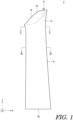
FIG. 1 is a front view showing a pointing device operating sleeve according to one embodiment. -
FIG. 2 is a rear view showing the sleeve ofFIG. 1 . -
FIG. 3 is a left side view showing the sleeve ofFIG. 1 . -
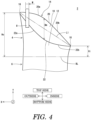
FIG. 4 is an enlarged view showing a part of the sleeve ofFIG. 2 . -
FIG. 5 is a sectional view taken along line V-V ofFIG. 1 . -
FIG. 6 is a sectional view taken along line VI-VI ofFIG. 1 . -
FIG. 7 is a front view showing the sleeve ofFIG. 1 together with an upper limb of a player. -
FIG. 8 is a sectional view taken along line VIII-VIII ofFIG. 7 . -
FIG. 9 is a front view showing, in an enlarged manner, a part of the sleeve ofFIG. 7 together with a hand of the player. -
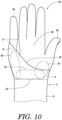
FIG. 10 is a rear view showing the sleeve ofFIG. 9 together with the hand of the player. -
FIG. 11 is an enlarged view showing a part of the sleeve ofFIG. 7 together with the hand of the player. -
FIG. 12 is an enlarged sectional view of a zone that is denoted by reference sign XII ofFIG. 11 . -
FIG. 13 is an enlarged view showing a part of the sleeve ofFIG. 7 together with the hand of the player. -
FIG. 14 is an enlarged sectional view of a zone that is denoted by reference sign XIV ofFIG. 13 . -
FIG. 15 is an enlarged rear view showing the sleeve ofFIG. 7 together with the hand of the player and a mouse. - Hereinafter, preferred embodiments are described in detail with reference to the accompanying drawings as necessary.
-
FIGS. 1 to 6 show a pointingdevice operating sleeve 2, which includes apalm cover 4 and anarm cover 6. Thesleeve 2 further includes aband 8. As described below in detail, thesleeve 2 is worn on the right upper extremity of a player. Although not illustrated, a sleeve for the left upper extremity has a shape that is left-right reversed from the shape of thesleeve 2 shown inFIG. 1 . InFIGS. 1 to 4 , an arrow X represents a width direction; an arrow Y represents a length direction; and an arrow Z represents a thickness direction. InFIG. 1 , the right side is the outside, and the left side is the inside. InFIGS. 2 and4 , the left side is the outside, and the right side is the inside. InFIGS. 1 to 4 , the upper side is the top side, and the lower side is the bottom side. - It is clear from
FIG. 5 that thepalm cover 4 is tubular. As shown inFIGS. 1 to 4 , thepalm cover 4 includes a back-side panel 10, a palm-side panel 12, and afirst opening 14. In the present embodiment, the palm-side panel 12 is integrated with the back-side panel 10. Accordingly, on thepalm cover 4, there is no visible boundary line between the back-side panel 10 and the palm-side panel 12. Alternatively, the palm-side panel 12 may be formed separately from the back-side panel 10, and may be joined to the back-side panel 10. In this case, there is a seam between the back-side panel 10 and the palm-side panel 12. Typically, the palm-side panel 12 is joined to the back-side panel 10 by sewing them together. - As shown in
FIG. 4 , thefirst opening 14 includes anoutside end 16, an insideend 18, a back-side edge 20, and a palm-side edge 22. In the present embodiment, theoutside end 16 is positioned on the top side (the upper side inFIG. 4 ) with respect to theinside end 18. The back-side edge 20 is positioned between theoutside end 16 and theinside end 18. Theoutside end 16 and theinside end 18 are not included in the back-side edge 20. The palm-side edge 22 is also positioned between theoutside end 16 and theinside end 18. Theoutside end 16 and theinside end 18 are not included in the palm-side edge 22. - In
FIG. 4 , denoted by reference sign L1 is a straight line that connects between theoutside end 16 and theinside end 18. The back-side edge 20 is, in its entirety, positioned on the top side (the upper side inFIG. 4 ) with respect to the straight line L1. The back-side edge 20 may be partly positioned on the top side with respect to the straight line L1. The palm-side edge 22 is, in its entirety, positioned on the bottom side (the lower side inFIG. 4 ) with respect to the straight line L1. The palm-side edge 22 may be partly positioned on the bottom side with respect to the straight line L1. - The palm-
side edge 22 is, in its entirety, positioned on the bottom side with respect to the back-side edge 20. In other words, at any position in the width direction X, the height of the palm-side edge 22 is less than the height of the back-side edge 20. In the present specification, the height is defined as a distance in the length direction Y from a boundary line BL (which will be described below in detail). The palm-side edge 22 may be partly positioned on the top side with respect to the back-side edge 20. - In the present embodiment, the back-
side edge 20 has a shape protruding toward the top side. The back-side edge 20 includes afirst edge 20a and asecond edge 20b. Thesecond edge 20b is positioned on the inside (the right side inFIG. 4 ) with respect to thefirst edge 20a. Thefirst edge 20a extends from the outside toward the inside and also toward the bottom side. In other words, the height of thefirst edge 20a decreases gradually from the outside toward the inside. Thesecond edge 20b also extends from the outside toward the inside and also toward the bottom side. In other words, the height of thesecond edge 20b decreases gradually from the outside toward the inside. The inclination angle of thesecond edge 20b relative to the width direction is greater than the inclination angle of thefirst edge 20a relative to the width direction. In other words, the decrease rate of the height of thesecond edge 20b is greater than the decrease rate of the height of thefirst edge 20a. The height of thefirst edge 20a may be constant from the outside toward the inside. - The palm-
side edge 22 has a shape protruding toward the bottom side. The palm-side edge 22 includes athird edge 22a and afourth edge 22b. Thefourth edge 22b is positioned on the inside with respect to thethird edge 22a. Thethird edge 22a extends from the outside toward the inside and also toward the bottom side. In other words, the height of thethird edge 22a decreases gradually from the outside toward the inside. Thefourth edge 22b also extends from the outside toward the inside and also toward the bottom side. In other words, the height of thefourth edge 22b decreases gradually from the outside toward the inside. The inclination angle of thethird edge 22a relative to the width direction is greater than the inclination angle of thefourth edge 22b relative to the width direction. In other words, the decrease rate of the height of thethird edge 22a is greater than the decrease rate of the height of thefourth edge 22b. The height of thefourth edge 22b may be constant from the outside toward the inside. - Due to the above-described shapes of the back-
side edge 20 and the palm-side edge 22, there is a difference between the area of the back-side panel 10 and the area of the palm-side panel 12. The area of the back-side panel 10 is greater than the area of the palm-side panel 12. That is, the area of the palm-side panel 12 is less than the area of the back-side panel 10. - It is clear from
FIG. 6 that thearm cover 6 is tubular. As shown inFIGS. 1 to 4 , thearm cover 6 is continuous with thepalm cover 4. In the present embodiment, thearm cover 6 is integrated with thepalm cover 4. Therefore, on thesleeve 2, the boundary line BL (seeFIG. 4 ) between thepalm cover 4 and thearm cover 6 is not visible. The boundary line BL coincides with the position of a wrist crease, which will be described below in detail. Thearm cover 6 includes asecond opening 24. - The
band 8 is attached to thepalm cover 4. The attachment of theband 8 to thepalm cover 4 is achieved by sewing both ends of theband 8 and the vicinities of both the ends on thepalm cover 4. Theband 8 may be attached to thepalm cover 4 not by sewing, but by other means. Theband 8 may be attachable to and detachable from thepalm cover 4. As shown inFIG. 3 , theband 8 forms ahole 26 on thesleeve 2. -
FIG. 7 is a front view showing the pointingdevice operating sleeve 2 ofFIG. 1 together with anupper limb 28 of the player. InFIG. 7 , ahand 30 is passed through thepalm cover 4. It is clear fromFIGS. 1 to 4 and7 that the diameter of thepalm cover 4 increases from the wrist toward the fingertips. Thepalm cover 4 having such a shape fits to thehand 30. - A forearm 32 (see
FIG. 8 ) is passed through thearm cover 6. Thearm cover 6 covers theentire forearm 32. A part of anupper arm 34 is also passed through thearm cover 6. Thearm cover 6 covers the part of theupper arm 34. It is clear fromFIGS. 1 to 4 and7 that the diameter of thearm cover 6 decreases from the elbow toward the wrist. Thearm cover 6 having such a shape fits to theforearm 32. Thesleeve 2 may include thearm cover 6 that does not cover theupper arm 34. Thesleeve 2 may include thearm cover 6 that covers a part of theforearm 32. -
FIG. 9 is a front view showing, in an enlarged manner, a part of the pointingdevice operating sleeve 2 ofFIG. 7 together with thehand 30 of the player.FIG. 9 shows a back 36, athumb 38, anindex finger 40, amiddle finger 42, aring finger 44, and alittle finger 46 of thehand 30. The back-side panel 10 covers a part of theback 36 of thehand 30. The back-side panel 10 covers none of the fingers. - In
FIG. 9 , thelittle finger 46 is passed through the hole 26 (seeFIG. 3 ). Thesleeve 2 may include thehole 26 through which thering finger 44 is passable. Thesleeve 2 may include thehole 26 through which thelittle finger 46 and thering finger 44 are passable. Preferably, thesleeve 2 includes thehole 26 through which only thelittle finger 46 is passed. -
FIG. 10 is a rear view showing, in an enlarged manner, a part of the pointingdevice operating sleeve 2 ofFIG. 7 together with thehand 30 of the player.FIG. 10 shows apalm 48. InFIG. 10 ,reference sign 50 indicates a wrist crease, andreference sign 52 indicates a palm heel. Thewrist crease 50 is a boundary between theforearm 32 and thepalm 48. Thepalm heel 52 is positioned on the top side with respect to thewrist crease 50. The palm-side panel 12 covers thepalm heel 52. In the present embodiment, the palm-side panel 12 covers theentire palm heel 52. - In
FIG. 10 ,reference sign 54 indicates a thenar eminence. Thethenar eminence 54 is a fleshy mound on thepalm 48 in the vicinity of the base of thethumb 38. The palm-side panel 12 covers a part of thethenar eminence 54. The palm-side panel 12 may cover the entirethenar eminence 54. - In
FIG. 10 ,reference sign 56 indicates a hypothenar eminence. Thehypothenar eminence 56 is a fleshy mound on thepalm 48 in the vicinity of the base of thelittle finger 46. The palm-side panel 12 covers the entirehypothenar eminence 56. The palm-side panel 12 may cover a part of thehypothenar eminence 56. -
FIG. 11 shows thesleeve 2 seen from the inside.FIG. 11 further shows thehand 30 of the player, amouse 58, and amouse pad 60.FIG. 11 shows thethumb 38, theindex finger 40, and themiddle finger 42 of thehand 30. Themouse 58 is placed over themouse pad 60. The player is holding themouse 58 with thehand 30. -
FIG. 12 is an enlarged sectional view of a zone that is denoted by reference sign XII ofFIG. 11 .FIG. 12 shows thethenar eminence 54, the palm-side panel 12 (i.e., the palm cover 4), and themouse pad 60. It is clear fromFIG. 12 that thepalm cover 4 is present between thethenar eminence 54 and themouse pad 60. When the player moves themouse 58 intensely, thepalm cover 4 suppresses direct rubbing between thethenar eminence 54 and themouse pad 60. Thepalm cover 4 protects thethenar eminence 54. -
FIG. 13 shows thesleeve 2 seen from the outside.FIG. 13 further shows thehand 30 of the player, themouse 58, and themouse pad 60.FIG. 13 shows themiddle finger 42, thering finger 44, and thelittle finger 46 of thehand 30. Themouse 58 is placed over themouse pad 60. The player is holding themouse 58 with thehand 30. -
FIG. 14 is an enlarged sectional view of a zone that is denoted by reference sign XIV ofFIG. 13 .FIG. 14 shows thehypothenar eminence 56, thepalm cover 4, and themouse pad 60. It is clear fromFIG. 14 that the palm-side panel 12 (i.e., the palm cover 4) is present between thehypothenar eminence 56 and themouse pad 60. When the player moves themouse 58 intensely, thepalm cover 4 suppresses direct rubbing between thehypothenar eminence 56 and themouse pad 60. Thepalm cover 4 protects thehypothenar eminence 56. - As shown in
FIG. 13 , theband 8 is engaged with aweb 62 between thering finger 44 and thelittle finger 46. Since theband 8 is attached to thepalm cover 4, theband 8 suppresses thepalm cover 4 from moving to the left inFIG. 13 . In other words, theband 8 suppresses displacement of thepalm cover 4 from thepalm 48. Thesleeve 2 is less likely to cause exposure of thethenar eminence 54 and thehypothenar eminence 56. Further, thesleeve 2 is less likely to cause hindrance to an action made by the player, the hindrance being due to displacement of thepalm cover 4. - Since the
little finger 46 or thering finger 44 is passed through thehole 26, theband 8 is away from thethumb 38, theindex finger 40, and themiddle finger 42. Further, thefirst opening 14 has the above-described shape. Accordingly, as shown inFIG. 10 , each of thethumb 38, theindex finger 40, and themiddle finger 42 is entirely exposed. Thesleeve 2 does not hinder movements of thethumb 38, theindex finger 40, and themiddle finger 42 of the player. Therefore, the player can readily operate the buttons of themouse 58 with thethumb 38, theindex finger 40, or themiddle finger 42. -
FIG. 15 shows, in an enlarged manner, thesleeve 2 ofFIG. 7 together with thehand 30 of the player and themouse 58.FIG. 15 shows thepalm 48, thethumb 38, thering finger 44, and thelittle finger 46. Each of thethumb 38, thering finger 44, and thelittle finger 46 is in contact with themouse 58. Although not illustrated, theindex finger 40 and themiddle finger 42 are in contact with the crown of the mouse 58 (see alsoFIG. 11 ). The player is holding themouse 58 with five fingers. - As previously described, the palm-
side edge 22 has a shape protruding toward the bottom side, and the area of the palm-side panel 12 is small. Therefore, as shown inFIG. 15 , when the player holds themouse 58, themouse 58 does not come into contact with the palm-side panel 12. Themouse 58 may come into slight contact with the palm-side panel 12. Since the contact between themouse 58 and the palm-side panel 12 is zero or a slight amount, displacement of the palm-side panel 12 with respect to thehand 30 due to the contact can be suppressed. Even in a case where the player operates themouse 58 over a long period of time, the palm-side panel 12 is less likely to get wrinkled. Thissleeve 2 can contribute to the operability of themouse 58. - As previously described, the back-
side edge 20 has a shape protruding toward the top side, and the area of the back-side panel 10 is large. Therefore, as shown inFIGS. 9 ,11 , and13 , the back-side panel 10 contacts theback 36 of the player over a wide area. This contact suppresses displacement of thepalm cover 4 with respect to thehand 30. - It is clear from
FIG. 4 that the height of the back-side edge 20 and the height of the palm-side edge 22 vary in the width direction X, and the difference between the height of the back-side edge 20 and the height of the palm-side edge 22 also vary in the width direction X. Reference sign Dm inFIG. 4 indicates the maximum value of the difference between the height of the back-side edge 20 and the height of the palm-side edge 22. Preferably, the maximum value Dm is greater than or equal to 20 mm. In a case where thesleeve 2 has the maximum value Dm of greater than or equal to 20 mm, the back-side panel 10 contacts the back 36 over a wide area, whereas the palm-side panel 12 does not contact or slightly contacts themouse 58. In light of this, the maximum value Dm is more preferably greater than or equal to 25 mm, and particularly preferably greater than or equal to 30 mm. If the back-side panel 10 covers the fingers, it hinders the fitting comfort. In light of fitting comfort, the maximum value Dm is preferably less than or equal to 50 mm. The maximum value Dm is measured in a state where nothing is passed through thesleeve 2. The maximum value Dm is measured in a state where no force, except the gravitational force, is applied to thesleeve 2. At the time of measuring the maximum value Dm, thesleeve 2 is placed on a horizontal surface. - In
FIG. 4 , an arrow Ho represents the height of theoutside end 16, and an arrow Hi represents the height of theinside end 18. As previously described, theoutside end 16 is positioned on the top side (the upper side inFIG. 1 ) with respect to theinside end 18. Therefore, the height Ho is greater than the height Hi. In other words, the difference (Ho - Hi) is greater than zero. - The difference (Ho - Hi) is preferably greater than or equal to 5 mm, more preferably greater than or equal to 10 mm, and particularly preferably greater than or equal to 15 mm from the viewpoint that the
palm cover 4 sufficiently protects thehypothenar eminence 56 and that thesleeve 2 is less likely to hinder movements of thethumb 38, theindex finger 40, and themiddle finger 42. The difference (Ho - Hi) is preferably less than or equal to 80 mm, more preferably less than or equal to 75 mm, and particularly preferably less than or equal to 70 mm. The difference (Ho - Hi) is measured in a state where nothing is passed through thesleeve 2. The difference (Ho - Hi) is measured in a state where no force, except the gravitational force, is applied to thesleeve 2. At the time of measuring the maximum value Dm, thesleeve 2 is placed on a horizontal surface. - In
FIG. 4 , an arrow W indicates the width of theband 8. The width W is preferably less than or equal to 20 mm, more preferably less than or equal to 16 mm, and particularly preferably less than or equal to 12 mm from the viewpoint that theband 8 is less likely to hinder movements of thehand 30 of the player. The width W is preferably greater than or equal to 2 mm, and particularly preferably greater than or equal to 4 mm from the viewpoint of suppressing tension applied to theweb 62 so that the player will be less likely to feel discomfort. - The
palm cover 4 may be obtained from a woven fabric, or may be obtained from a knitted material. Preferably, thepalm cover 4 has elasticity, low frictional property, and water absorbability. Preferable examples of the material of thepalm cover 4 include polyester, polyurethane, nylon, rayon, and acrylic. The material of thepalm cover 4 may be a mixture of a plurality of raw materials. The material of thepalm cover 4 may be spandex. - The
arm cover 6 may be obtained from a woven fabric, or may be obtained from a knitted material. Preferably, thearm cover 6 has elasticity, low frictional property, and water absorbability. Preferable examples of the material of thearm cover 6 include polyester, polyurethane, nylon, rayon, and acrylic. The material of thearm cover 6 may be a mixture of a plurality of raw materials. The material of thearm cover 6 may be spandex. In the present embodiment, the material of thearm cover 6 and the material of thepalm cover 4 are the same. Thearm cover 6 may include a material that is different from the material of thepalm cover 4. - The material of the
band 8 may be an elastic material or a non-elastic material. Examples of the non-elastic material include cotton. - The
sleeve 2 is also suitable for use in operating a pointing device different from themouse 58. For example, thesleeve 2 is also suitable for use in operating a stick and a track ball. Thissleeve 2 may be worn by an operator who operates a personal computer or the like. - The following elucidates the effects of the pointing device operating sleeve according to Examples. However, the scope of the disclosure in the present specification should not be restrictively construed based on the description of the Examples.
- The pointing device operating sleeve shown in
FIGS. 1 to 15 was produced. The sleeve includes the band as a stopper. The dimensions of the sleeve were as shown below. - Height Ho: 428 mm
- Height Hi: 367mm
- Difference (Ho - Hi): 61 mm
- Dm: 35 mm
- Width W: 10 mm
- A sleeve was obtained in the same manner as Example 1 except that the shape of the palm-side panel was changed and the maximum value Dm was set to 20 mm. A player wearing this sleeve operated a shooting game mouse. The palm-side panel came into slight contact with the mouse, and displacement of the palm cover occurred.
- A sleeve was obtained in the same manner as Example 1, except that the palm-side panel was made congruent in shape with the back-side panel. The maximum value Dm of the sleeve was 0 mm. A player wearing this sleeve operated a shooting game mouse. The palm-side panel came into intense contact with the mouse, and significant displacement of the palm cover occurred.
- These evaluation results clearly indicate the superiority of the sleeve according to each Example.
- The following items each disclose a preferred embodiment.
- A pointing device operating sleeve including: a palm cover configured to cover a part of a palm, the palm cover including a first opening; and an arm cover configured to cover at least a part of a forearm, the arm cover being continuous with the palm cover and including a second opening, wherein: the first opening includes an outside end, an inside end, a back-side edge, and a palm-side edge, the back-side edge and the palm-side edge each being positioned between the outside end and the inside end; and the palm-side edge is, at least partly, positioned on a bottom side with respect to the back-side edge.
- The sleeve according to item 1, wherein a maximum value of a difference between a height of the back-side edge and a height of the palm-side edge is greater than or equal to 20 mm.
- The sleeve according to
item 1 or 2, wherein the palm-side edge is, in its entirety, positioned on the bottom side with respect to the back-side edge. - The sleeve according to any one of items 1 to 3, wherein the palm-side edge is, at least partly, positioned on the bottom side with respect to a straight line that connects between the outside end and the inside end.
- The sleeve according to
item 4, wherein the palm-side edge is, in its entirety, positioned on the bottom side with respect to the straight line. - The sleeve according to any one of items 1 to 5, wherein the back-side edge is, at least partly, positioned on a top side with respect to a straight line that connects between the outside end and the inside end.
- The sleeve according to
item 6, wherein the back-side edge is, in its entirety, positioned on the top side with respect to the straight line. - The sleeve according to any one of items 1 to 7, wherein the palm-side edge has a shape protruding toward the bottom side, and the back-side edge has a shape protruding toward a top side.
- The sleeve according to any one of items 1 to 8, wherein: the back-side edge includes a first edge and a second edge, the second edge being positioned on an inside with respect to the first edge; a height of the first edge decreases gradually from an outside toward the inside; a height of the second edge decreases gradually from the outside toward the inside; and a decrease rate of the height of the second edge is greater than a decrease rate of the height of the first edge.
- The sleeve according to any one of items 1 to 9, wherein: the palm-side edge includes a third edge and a fourth edge, the fourth edge being positioned on an inside with respect to the third edge; a height of the third edge decreases gradually from an outside toward the inside; a height of the fourth edge decreases gradually from the outside toward the inside; and a decrease rate of the height of the third edge is greater than a decrease rate of the height of the fourth edge.
- The sleeve according to any one of items 1 to 10, wherein the palm cover includes a back-side panel and a palm-side panel, the palm-side panel having an area that is less than an area of the back-side panel.
- The sleeve according to any one of items 1 to 11, wherein a height of the outside end is greater than a height of the inside end.
- The above-described sleeve is suitable for use by various e-sports players. This sleeve is also suitable for use in different applications other than e-sports.
-
- 2
- pointing device operating sleeve
- 4
- palm cover
- 6
- arm cover
- 8
- band
- 10
- back-side panel
- 12
- palm-side panel
- 14
- first opening
- 16
- outside end
- 18
- inside end
- 20
- back-side edge
- 20a
- first edge
- 20b
- second edge
- 22
- palm-side edge
- 22a
- third edge
- 22b
- fourth edge
- 24
- second opening
- 26
- hole
- 58
- mouse
- 60
- mouse pad
Claims (12)
- A pointing device operating sleeve comprising:a palm cover configured to cover a part of a palm, the palm cover including a first opening; andan arm cover configured to cover at least a part of a forearm, the arm cover being continuous with the palm cover and including a second opening, wherein:the first opening includes an outside end, an inside end, a back-side edge, and a palm-side edge, the back-side edge and the palm-side edge each being positioned between the outside end and the inside end; andthe palm-side edge is, at least partly, positioned on a bottom side with respect to the back-side edge.
- The sleeve according to claim 1, wherein
a maximum value of a difference between a height of the back-side edge and a height of the palm-side edge is greater than or equal to 20 mm. - The sleeve according to claim 1 or 2, wherein
the palm-side edge is, in its entirety, positioned on the bottom side with respect to the back-side edge. - The sleeve according to claim 1 or 2, wherein
the palm-side edge is, at least partly, positioned on the bottom side with respect to a straight line that connects between the outside end and the inside end. - The sleeve according to claim 4, wherein
the palm-side edge is, in its entirety, positioned on the bottom side with respect to the straight line. - The sleeve according to claim 1 or 2, wherein
the back-side edge is, at least partly, positioned on a top side with respect to a straight line that connects between the outside end and the inside end. - The sleeve according to claim 6, wherein
the back-side edge is, in its entirety, positioned on the top side with respect to the straight line. - The sleeve according to claim 1 or 2, wherein
the palm-side edge has a shape protruding toward the bottom side, and the back-side edge has a shape protruding toward a top side. - The sleeve according to claim 1 or 2, wherein:the back-side edge includes a first edge and a second edge, the second edge being positioned on an inside with respect to the first edge;a height of the first edge decreases gradually from an outside toward the inside;a height of the second edge decreases gradually from the outside toward the inside; anda decrease rate of the height of the second edge is greater than a decrease rate of the height of the first edge.
- The sleeve according to claim 1 or 2, wherein:the palm-side edge includes a third edge and a fourth edge, the fourth edge being positioned on an inside with respect to the third edge;a height of the third edge decreases gradually from an outside toward the inside;a height of the fourth edge decreases gradually from the outside toward the inside; anda decrease rate of the height of the third edge is greater than a decrease rate of the height of the fourth edge.
- The sleeve according to claim 1 or 2, wherein
the palm cover includes a back-side panel and a palm-side panel, the palm-side panel having an area that is less than an area of the back-side panel. - The sleeve according to claim 1 or 2, wherein
a height of the outside end is greater than a height of the inside end.
Applications Claiming Priority (2)
| Application Number | Priority Date | Filing Date | Title |
|---|---|---|---|
| JP2022148761A JP2024043654A (en) | 2022-09-20 | 2022-09-20 | Sleeve for pointing device operation |
| PCT/JP2023/021497 WO2024062698A1 (en) | 2022-09-20 | 2023-06-09 | Sleeve for operating pointing devices |
Publications (2)
| Publication Number | Publication Date |
|---|---|
| EP4579402A1 true EP4579402A1 (en) | 2025-07-02 |
| EP4579402A4 EP4579402A4 (en) | 2025-12-10 |
Family
ID=90454334
Family Applications (1)
| Application Number | Title | Priority Date | Filing Date |
|---|---|---|---|
| EP23867827.0A Pending EP4579402A4 (en) | 2022-09-20 | 2023-06-09 | SLEEVE FOR OPERATION OF INDICATORS |
Country Status (5)
| Country | Link |
|---|---|
| US (1) | US20260060345A1 (en) |
| EP (1) | EP4579402A4 (en) |
| JP (1) | JP2024043654A (en) |
| KR (1) | KR20250072975A (en) |
| WO (1) | WO2024062698A1 (en) |
Family Cites Families (35)
| Publication number | Priority date | Publication date | Assignee | Title |
|---|---|---|---|---|
| US925952A (en) * | 1909-06-22 | Slbeve-pbotectob | ||
| US375958A (en) * | 1888-01-03 | Plasterer s jacket | ||
| US2150069A (en) * | 1937-11-16 | 1939-03-07 | Joseph J Koleno | Berry picking sleeve |
| US3037209A (en) * | 1960-11-18 | 1962-06-05 | Surgical Appliance Ind | Football glove |
| US3924272A (en) * | 1974-05-03 | 1975-12-09 | George H Allen | Protective device for use by football athletes |
| USD257408S (en) * | 1978-11-13 | 1980-10-21 | Talty Francis P | Combined wristband and handcover |
| US5357633A (en) * | 1993-02-25 | 1994-10-25 | Rael George V | Arm protective garment |
| US5459883A (en) * | 1994-03-09 | 1995-10-24 | Garceau-Verbeck; Dorothy S. | Ergonomic hand covering and grip enhancer |
| US5628062A (en) * | 1995-12-11 | 1997-05-13 | Tseng; Li Ming | Arm and hand UV protection sleeve for driving |
| USD385666S (en) * | 1996-08-21 | 1997-10-28 | Hector Abreu | Protective one finger glove |
| US5918315A (en) * | 1997-02-14 | 1999-07-06 | Trachtenberg; Steven | Utilitarian fashion sleeve |
| US5878435A (en) * | 1997-11-12 | 1999-03-09 | Kast; Rhonda S. | Hand and forearm protector |
| US6443921B1 (en) * | 1998-08-07 | 2002-09-03 | Evelyn Kaplan | Carpal tunnel protector |
| JP2000282312A (en) * | 1999-03-30 | 2000-10-10 | Koji Ariki | Gloves |
| JP2001265529A (en) | 2000-03-16 | 2001-09-28 | Nitto Kogyo Co Ltd | Protection tool for mouse operation of personal computer and mouse with protection tool |
| US6199211B1 (en) * | 2000-07-20 | 2001-03-13 | Marc Franzolino | Ergonomic hand, wrist and forearm supporter |
| US6729979B1 (en) * | 2002-06-04 | 2004-05-04 | Donald E. Gugel | Basketball shooting trainer device |
| US6826779B1 (en) * | 2003-08-25 | 2004-12-07 | Mckenzie Mark Christopher | Arm protection device |
| US6813779B1 (en) * | 2004-03-04 | 2004-11-09 | Chris Williams | Arm protector |
| US7694348B1 (en) * | 2008-02-22 | 2010-04-13 | Stephen Smith | Method and apparatus of preventing sunburn |
| US9066546B2 (en) * | 2009-11-05 | 2015-06-30 | Jamie Getzwiller | Hand and foot yoga garments with enhanced positional stability and comfort |
| US20120023633A1 (en) * | 2010-07-27 | 2012-02-02 | Veronica Kummerfeldt | Protective hand guard |
| USD649293S1 (en) * | 2011-03-04 | 2011-11-22 | Lyons Frank T | Arm protector for blocking sunlight while driving |
| US9330799B1 (en) * | 2015-02-10 | 2016-05-03 | D. Bruce Phillips | Garment for protection from ultraviolet radiation |
| US9820516B2 (en) * | 2015-02-18 | 2017-11-21 | Patricia Ferrer | Open-palm sun protective glove |
| US20160309810A1 (en) * | 2015-04-23 | 2016-10-27 | Sarah Irene Jones | Wearable device for cleaning tools when trimming plants |
| US10076144B2 (en) * | 2015-11-17 | 2018-09-18 | Migdalia Rivera | Elongated wrist towel with elastic rim and seam |
| KR101764526B1 (en) * | 2016-02-12 | 2017-08-02 | 아주대학교산학협력단 | Functional gloves for grasping ultrasonic probe |
| US10405590B2 (en) * | 2017-03-15 | 2019-09-10 | Veronica Crayton | Sun blocking assembly |
| US11064743B2 (en) * | 2018-07-22 | 2021-07-20 | Hand Temple | Garments for protecting backs of hands |
| TWI832896B (en) * | 2018-09-13 | 2024-02-21 | 日商興和股份有限公司 | Supporter |
| JP1634432S (en) * | 2018-09-25 | 2019-06-17 | ||
| US20210204623A1 (en) * | 2020-01-08 | 2021-07-08 | II Cesar Flores | Fingerless computer input glove for use with a computer mouse or trackball |
| US20230036634A1 (en) * | 2021-07-29 | 2023-02-02 | Alvin Kirby | Grasping Assist Device |
| JP2023107330A (en) * | 2022-01-24 | 2023-08-03 | 住友ゴム工業株式会社 | Sleeve for pointing device operation |
-
2022
- 2022-09-20 JP JP2022148761A patent/JP2024043654A/en active Pending
-
2023
- 2023-06-09 US US19/106,106 patent/US20260060345A1/en active Pending
- 2023-06-09 KR KR1020257009928A patent/KR20250072975A/en active Pending
- 2023-06-09 WO PCT/JP2023/021497 patent/WO2024062698A1/en not_active Ceased
- 2023-06-09 EP EP23867827.0A patent/EP4579402A4/en active Pending
Also Published As
| Publication number | Publication date |
|---|---|
| EP4579402A4 (en) | 2025-12-10 |
| US20260060345A1 (en) | 2026-03-05 |
| JP2024043654A (en) | 2024-04-02 |
| WO2024062698A1 (en) | 2024-03-28 |
| KR20250072975A (en) | 2025-05-26 |
Similar Documents
| Publication | Publication Date | Title |
|---|---|---|
| US6009557A (en) | Video game control glove | |
| CN207653644U (en) | Gloves | |
| US8341767B2 (en) | Protective glove having contoured wrist guard | |
| US7318241B2 (en) | Padded sports glove having improved flexibility and breathability | |
| US6209137B1 (en) | Video game glove | |
| CN101316634B (en) | Golf glove | |
| US8262594B2 (en) | Reinforced support device | |
| CA2919472C (en) | Sports glove with inverted finger pads | |
| US20100095428A1 (en) | Glove Incorporating A Silicone Material | |
| JP2007506521A (en) | Work gloves | |
| US20190091547A1 (en) | Athletic Glove | |
| US8719963B2 (en) | Protective glove having segmented wrist guard | |
| US20110173733A1 (en) | Hand wrist and forearm protection glove | |
| US20090113592A1 (en) | Shock absorber for sports | |
| US10252144B2 (en) | Glove for a hockey or lacrosse player | |
| US12373042B2 (en) | Pointing device operating sleeve | |
| US20260060345A1 (en) | Pointing device operating sleeve | |
| US20080000008A1 (en) | Glove | |
| US7458107B2 (en) | Athletic glove with wrist protection | |
| US20080034471A1 (en) | Hockey glove | |
| JP5476640B2 (en) | Baseball or softball catcher | |
| CN206744656U (en) | Gloves for game | |
| JP7215686B2 (en) | golf gloves | |
| CA2639950C (en) | Protective glove having contoured wrist guard | |
| JP2022038398A (en) | Glove for use in game |
Legal Events
| Date | Code | Title | Description |
|---|---|---|---|
| STAA | Information on the status of an ep patent application or granted ep patent |
Free format text: STATUS: THE INTERNATIONAL PUBLICATION HAS BEEN MADE |
|
| PUAI | Public reference made under article 153(3) epc to a published international application that has entered the european phase |
Free format text: ORIGINAL CODE: 0009012 |
|
| STAA | Information on the status of an ep patent application or granted ep patent |
Free format text: STATUS: REQUEST FOR EXAMINATION WAS MADE |
|
| 17P | Request for examination filed |
Effective date: 20250324 |
|
| AK | Designated contracting states |
Kind code of ref document: A1 Designated state(s): AL AT BE BG CH CY CZ DE DK EE ES FI FR GB GR HR HU IE IS IT LI LT LU LV MC ME MK MT NL NO PL PT RO RS SE SI SK SM TR |
|
| A4 | Supplementary search report drawn up and despatched |
Effective date: 20251111 |
|
| RIC1 | Information provided on ipc code assigned before grant |
Ipc: G06F 3/039 20130101AFI20251105BHEP Ipc: A41D 13/00 20060101ALI20251105BHEP Ipc: A41D 27/10 20060101ALI20251105BHEP Ipc: A63F 13/98 20140101ALI20251105BHEP |
|
| DAV | Request for validation of the european patent (deleted) | ||
| DAX | Request for extension of the european patent (deleted) | ||
| P01 | Opt-out of the competence of the unified patent court (upc) registered |
Free format text: CASE NUMBER: UPC_APP_0005183_4579402/2026 Effective date: 20260212 |