EP4579367A1 - Drone operation system provided with kiosk and station for drone control - Google Patents
Drone operation system provided with kiosk and station for drone control Download PDFInfo
- Publication number
- EP4579367A1 EP4579367A1 EP23857539.3A EP23857539A EP4579367A1 EP 4579367 A1 EP4579367 A1 EP 4579367A1 EP 23857539 A EP23857539 A EP 23857539A EP 4579367 A1 EP4579367 A1 EP 4579367A1
- Authority
- EP
- European Patent Office
- Prior art keywords
- drone
- kiosk
- station
- flight
- transceiver
- Prior art date
- Legal status (The legal status is an assumption and is not a legal conclusion. Google has not performed a legal analysis and makes no representation as to the accuracy of the status listed.)
- Pending
Links
Images


Classifications
-
- B—PERFORMING OPERATIONS; TRANSPORTING
- B64—AIRCRAFT; AVIATION; COSMONAUTICS
- B64U—UNMANNED AERIAL VEHICLES [UAV]; EQUIPMENT THEREFOR
- B64U80/00—Transport or storage specially adapted for UAVs
- B64U80/20—Transport or storage specially adapted for UAVs with arrangements for servicing the UAV
- B64U80/25—Transport or storage specially adapted for UAVs with arrangements for servicing the UAV for recharging batteries; for refuelling
-
- B—PERFORMING OPERATIONS; TRANSPORTING
- B60—VEHICLES IN GENERAL
- B60L—PROPULSION OF ELECTRICALLY-PROPELLED VEHICLES; SUPPLYING ELECTRIC POWER FOR AUXILIARY EQUIPMENT OF ELECTRICALLY-PROPELLED VEHICLES; ELECTRODYNAMIC BRAKE SYSTEMS FOR VEHICLES IN GENERAL; MAGNETIC SUSPENSION OR LEVITATION FOR VEHICLES; MONITORING OPERATING VARIABLES OF ELECTRICALLY-PROPELLED VEHICLES; ELECTRIC SAFETY DEVICES FOR ELECTRICALLY-PROPELLED VEHICLES
- B60L53/00—Methods of charging batteries, specially adapted for electric vehicles; Charging stations or on-board charging equipment therefor; Exchange of energy storage elements in electric vehicles
- B60L53/10—Methods of charging batteries, specially adapted for electric vehicles; Charging stations or on-board charging equipment therefor; Exchange of energy storage elements in electric vehicles characterised by the energy transfer between the charging station and the vehicle
- B60L53/14—Conductive energy transfer
-
- B—PERFORMING OPERATIONS; TRANSPORTING
- B60—VEHICLES IN GENERAL
- B60L—PROPULSION OF ELECTRICALLY-PROPELLED VEHICLES; SUPPLYING ELECTRIC POWER FOR AUXILIARY EQUIPMENT OF ELECTRICALLY-PROPELLED VEHICLES; ELECTRODYNAMIC BRAKE SYSTEMS FOR VEHICLES IN GENERAL; MAGNETIC SUSPENSION OR LEVITATION FOR VEHICLES; MONITORING OPERATING VARIABLES OF ELECTRICALLY-PROPELLED VEHICLES; ELECTRIC SAFETY DEVICES FOR ELECTRICALLY-PROPELLED VEHICLES
- B60L53/00—Methods of charging batteries, specially adapted for electric vehicles; Charging stations or on-board charging equipment therefor; Exchange of energy storage elements in electric vehicles
- B60L53/30—Constructional details of charging stations
- B60L53/305—Communication interfaces
-
- B—PERFORMING OPERATIONS; TRANSPORTING
- B60—VEHICLES IN GENERAL
- B60L—PROPULSION OF ELECTRICALLY-PROPELLED VEHICLES; SUPPLYING ELECTRIC POWER FOR AUXILIARY EQUIPMENT OF ELECTRICALLY-PROPELLED VEHICLES; ELECTRODYNAMIC BRAKE SYSTEMS FOR VEHICLES IN GENERAL; MAGNETIC SUSPENSION OR LEVITATION FOR VEHICLES; MONITORING OPERATING VARIABLES OF ELECTRICALLY-PROPELLED VEHICLES; ELECTRIC SAFETY DEVICES FOR ELECTRICALLY-PROPELLED VEHICLES
- B60L53/00—Methods of charging batteries, specially adapted for electric vehicles; Charging stations or on-board charging equipment therefor; Exchange of energy storage elements in electric vehicles
- B60L53/30—Constructional details of charging stations
- B60L53/31—Charging columns specially adapted for electric vehicles
-
- B—PERFORMING OPERATIONS; TRANSPORTING
- B60—VEHICLES IN GENERAL
- B60L—PROPULSION OF ELECTRICALLY-PROPELLED VEHICLES; SUPPLYING ELECTRIC POWER FOR AUXILIARY EQUIPMENT OF ELECTRICALLY-PROPELLED VEHICLES; ELECTRODYNAMIC BRAKE SYSTEMS FOR VEHICLES IN GENERAL; MAGNETIC SUSPENSION OR LEVITATION FOR VEHICLES; MONITORING OPERATING VARIABLES OF ELECTRICALLY-PROPELLED VEHICLES; ELECTRIC SAFETY DEVICES FOR ELECTRICALLY-PROPELLED VEHICLES
- B60L58/00—Methods or circuit arrangements for monitoring or controlling batteries or fuel cells, specially adapted for electric vehicles
- B60L58/10—Methods or circuit arrangements for monitoring or controlling batteries or fuel cells, specially adapted for electric vehicles for monitoring or controlling batteries
- B60L58/12—Methods or circuit arrangements for monitoring or controlling batteries or fuel cells, specially adapted for electric vehicles for monitoring or controlling batteries responding to state of charge [SoC]
-
- B—PERFORMING OPERATIONS; TRANSPORTING
- B64—AIRCRAFT; AVIATION; COSMONAUTICS
- B64U—UNMANNED AERIAL VEHICLES [UAV]; EQUIPMENT THEREFOR
- B64U50/00—Propulsion; Power supply
- B64U50/30—Supply or distribution of electrical power
- B64U50/37—Charging when not in flight
- B64U50/38—Charging when not in flight by wireless transmission
-
- B—PERFORMING OPERATIONS; TRANSPORTING
- B64—AIRCRAFT; AVIATION; COSMONAUTICS
- B64U—UNMANNED AERIAL VEHICLES [UAV]; EQUIPMENT THEREFOR
- B64U80/00—Transport or storage specially adapted for UAVs
- B64U80/30—Transport or storage specially adapted for UAVs with arrangements for data transmission
-
- G—PHYSICS
- G05—CONTROLLING; REGULATING
- G05D—SYSTEMS FOR CONTROLLING OR REGULATING NON-ELECTRIC VARIABLES
- G05D1/00—Control of position, course, altitude or attitude of land, water, air or space vehicles, e.g. using automatic pilots
- G05D1/20—Control system inputs
- G05D1/22—Command input arrangements
- G05D1/221—Remote-control arrangements
- G05D1/222—Remote-control arrangements operated by humans
- G05D1/223—Command input arrangements on the remote controller, e.g. joysticks or touch screens
- G05D1/2232—Touch screens
-
- B—PERFORMING OPERATIONS; TRANSPORTING
- B60—VEHICLES IN GENERAL
- B60L—PROPULSION OF ELECTRICALLY-PROPELLED VEHICLES; SUPPLYING ELECTRIC POWER FOR AUXILIARY EQUIPMENT OF ELECTRICALLY-PROPELLED VEHICLES; ELECTRODYNAMIC BRAKE SYSTEMS FOR VEHICLES IN GENERAL; MAGNETIC SUSPENSION OR LEVITATION FOR VEHICLES; MONITORING OPERATING VARIABLES OF ELECTRICALLY-PROPELLED VEHICLES; ELECTRIC SAFETY DEVICES FOR ELECTRICALLY-PROPELLED VEHICLES
- B60L2200/00—Type of vehicles
- B60L2200/10—Air crafts
-
- B—PERFORMING OPERATIONS; TRANSPORTING
- B60—VEHICLES IN GENERAL
- B60L—PROPULSION OF ELECTRICALLY-PROPELLED VEHICLES; SUPPLYING ELECTRIC POWER FOR AUXILIARY EQUIPMENT OF ELECTRICALLY-PROPELLED VEHICLES; ELECTRODYNAMIC BRAKE SYSTEMS FOR VEHICLES IN GENERAL; MAGNETIC SUSPENSION OR LEVITATION FOR VEHICLES; MONITORING OPERATING VARIABLES OF ELECTRICALLY-PROPELLED VEHICLES; ELECTRIC SAFETY DEVICES FOR ELECTRICALLY-PROPELLED VEHICLES
- B60L2250/00—Driver interactions
- B60L2250/10—Driver interactions by alarm
-
- B—PERFORMING OPERATIONS; TRANSPORTING
- B60—VEHICLES IN GENERAL
- B60L—PROPULSION OF ELECTRICALLY-PROPELLED VEHICLES; SUPPLYING ELECTRIC POWER FOR AUXILIARY EQUIPMENT OF ELECTRICALLY-PROPELLED VEHICLES; ELECTRODYNAMIC BRAKE SYSTEMS FOR VEHICLES IN GENERAL; MAGNETIC SUSPENSION OR LEVITATION FOR VEHICLES; MONITORING OPERATING VARIABLES OF ELECTRICALLY-PROPELLED VEHICLES; ELECTRIC SAFETY DEVICES FOR ELECTRICALLY-PROPELLED VEHICLES
- B60L2260/00—Operating Modes
- B60L2260/20—Drive modes; Transition between modes
- B60L2260/32—Auto pilot mode
-
- B—PERFORMING OPERATIONS; TRANSPORTING
- B64—AIRCRAFT; AVIATION; COSMONAUTICS
- B64U—UNMANNED AERIAL VEHICLES [UAV]; EQUIPMENT THEREFOR
- B64U2201/00—UAVs characterised by their flight controls
- B64U2201/20—Remote controls
-
- G—PHYSICS
- G05—CONTROLLING; REGULATING
- G05D—SYSTEMS FOR CONTROLLING OR REGULATING NON-ELECTRIC VARIABLES
- G05D2105/00—Specific applications of the controlled vehicles
- G05D2105/20—Specific applications of the controlled vehicles for transportation
- G05D2105/28—Specific applications of the controlled vehicles for transportation of freight
-
- G—PHYSICS
- G05—CONTROLLING; REGULATING
- G05D—SYSTEMS FOR CONTROLLING OR REGULATING NON-ELECTRIC VARIABLES
- G05D2107/00—Specific environments of the controlled vehicles
- G05D2107/30—Off-road
- G05D2107/34—Battlefields
-
- G—PHYSICS
- G05—CONTROLLING; REGULATING
- G05D—SYSTEMS FOR CONTROLLING OR REGULATING NON-ELECTRIC VARIABLES
- G05D2109/00—Types of controlled vehicles
- G05D2109/20—Aircraft, e.g. drones
- G05D2109/25—Rotorcrafts
Definitions
- the present disclosure relates to a drone operation system having a kiosk and a station for controlling a drone that can replace an existing manual controller or a computer-based ground control system and can conveniently operate a drone by operating a drone using a kiosk having a touch screen.
- the drone station (Narma Inc.) that includes: a roof on which a drone is landed; a side wall erected around the roof from the bottom of the roof; a nozzle formed at the edge where the roof and the side wall intersect each other and spraying airflow upward; a grill formed at the side wall 12 so that external air flows inside; a panel disposed inside the grill and guiding fluid flow such that fluid flows from the grill to the nozzle; and a rotor disposed inside the guide panel and moving fluid from the grill to the nozzle by rotating, and further includes a stabilizer disposed inside the side wall to control the flow rate, flow speed, and spray direction of fluid moving to the nozzle has been disclosed in Korean Patent No. 10-2335592 .
- FIG. 1a shows a manual controller
- FIG. 1b shows a ground control system.
- lithium polymer batteries that are most generally used for drones are stored for a long time (1 week) in a 100% fully charged state, the performance is quickly deteriorated, so they are discarded in many cases.
- lithium polymer batteries should be stored in a storage mode of 50 ⁇ 80% charging.
- it is required to always keep a drone in an on-mode in order to keep a golden time for drones that carry emergency articles for emergency patients, and to this end, there is a need for a station that always keeps a drone battery in 70%.
- An objective of the present disclosure is to provide a UAV delivery and operation station that can replace an existing manual controller or a computer-based ground control system and can conveniently operate a drone by operating a drone using a kiosk having a touch screen.
- An objective of the present disclosure is to provide a UAV delivery and operation station that makes it easy to operate a drone that flies through a designated route of a standby state and makes a safe takeoff and charging management of a drone.
- An objective of the present disclosure is to provide a drone operation system having a kiosk and a station for controlling a drone that is suitable for delivering emergency articles, such as an AED, and a military emergency articles (ammunition, shells, medical articles for soldiers, food, medicine) for a war.
- emergency articles such as an AED
- military emergency articles ammunition, shells, medical articles for soldiers, food, medicine
- a drone operation system having a kiosk and a station for controlling a drone of the present disclosure includes: a drone control device; a station (200) providing a drone standby and landing place; and a drone (300) operated in accordance with instructions from the drone control device, wherein the drone control device includes: a flight route storage (110) storing designated flight routes (GPS information) stored in advance for delivery destinations, respectively; and a first transceiver (140) transmitting the designated flight routes (GPS information) to the drone (300) using LTE or RF.
- the drone control device is a kiosk (100) having a touch screen (120 through which touch-type input is possible, and includes: a control unit (130) connected with the flight route storage (110), the touch screen (120), and the first transceiver (140); and a second transceiver (150) communicating with the station (200).
- the touch screen (120) of the kiosk (100) includes: a start button positioned in a start image; a destination selection button (122) positioned in a main image to send the drone; and a flight button (123) starting to fly the drone by clicking a flight button positioned in a drone start image.
- the drone control kiosk is configured such that when it is required to change a drone destination in the drone start image, it is possible to select again a destination in a destination image by clicking a back button.
- the station (200) includes: a third transceiver (250) communicating with the transceiver (150) using Bluetooth; a human sensor (240) sensing human around the station; and a charging manager (230) managing the charging state of the drone (300), and when a flight start instruction is transmitted from the kiosk (100) and then a human sensing signal is generated from the human sensor (240), the third transceiver (250) transmits a takeoff delay signal due to human sensing to the control unit (120) of the kiosk (100).
- a UAV delivery and operation station that makes it easy to operate a drone that flies through a designated route of a standby state and makes a safe takeoff and charging management of a drone.
- a UAV delivery and operation station that is suitable for an emergency article delivery drone that delivers emergency articles such as an AED, an emergency rescue articles, and medicine, or a delivery drone for munitions that delivers military emergency articles (ammunition, shells, emergency medical articles, food) for a war.
- emergency articles such as an AED, an emergency rescue articles, and medicine
- a delivery drone for munitions that delivers military emergency articles (ammunition, shells, emergency medical articles, food) for a war.
- FIGS. 2a , 2b, and 2c are configuration views of an entire drone delivery system having a kiosk and a station for controlling a drone, a kiosk, and a station of the present disclosure
- FIG. 3 is a detailed configuration view of the drone operation system having a kiosk and a station for controlling a drone
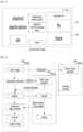
- FIG. 4 is a configuration view of a menu of a kiosk for controlling a drone (destination selection)
- FIG. 5 is a configuration view of a menu of a kiosk for controlling a drone (flight start and destination reselection)
- FIG. 6 is a configuration view showing controlling a drone through a drone control kiosk
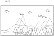
- FIG. 7 is a view showing the concept of a designated route delivery of a drone.
- a drone operation system having a kiosk and a station for controlling a drone includes a drone control device, a station 200 providing drone standby and takeoff place, and a drone 300 that is moved in accordance with instructions from the drone control device.
- the drone control device includes a flight route storage 110 storing designated flight routes (GPS information) stored in advance for destinations, respectively, and a first transceiver 140 transmitting the designated flight routes (GPS information) to the drone 300 using LTE or RF.
- GPS information designated flight routes
- first transceiver 140 transmitting the designated flight routes (GPS information) to the drone 300 using LTE or RF.
- the touch screen 120 of the kiosk 100 includes a start button positioned in a start image, a destination selection buttons 122 positioned in a main image to send the drone, and a flight button 123 starting to fly the drone by clicking a flight button positioned in a drone start image.
- control unit 130 of the drone control device uploads a flight route of a destination input through the touch screen 120 from the flight route storage 110 and transmits the flight route to the drone 300 through the first receiver 140.
- the drone 300 may be a delivery drone.
- the station 200 includes a third transceiver 250 communicating with the transceiver 150 for the station using Bluetooth, a human sensor 240 sensing human around the station, and a charging manager 230 managing the charging state of the drone 300.
- the station 200 and the drone 300 are connected through a wire, but power is supplied through a wire connected to a magnet for a quick takeoff.
Landscapes
- Engineering & Computer Science (AREA)
- Transportation (AREA)
- Remote Sensing (AREA)
- Aviation & Aerospace Engineering (AREA)
- Power Engineering (AREA)
- Mechanical Engineering (AREA)
- Computer Networks & Wireless Communication (AREA)
- Sustainable Development (AREA)
- Life Sciences & Earth Sciences (AREA)
- Sustainable Energy (AREA)
- Radar, Positioning & Navigation (AREA)
- Physics & Mathematics (AREA)
- General Physics & Mathematics (AREA)
- Automation & Control Theory (AREA)
- Chemical & Material Sciences (AREA)
- Combustion & Propulsion (AREA)
- Control Of Position, Course, Altitude, Or Attitude Of Moving Bodies (AREA)
- Selective Calling Equipment (AREA)
Abstract
The present disclosure relates to a drone operation system having a kiosk and a station for controlling a drone that includes: a drone control device; a station (200) providing a drone standby and landing place; and a drone (300) operated in accordance with instructions from the drone control device, wherein the drone control device includes: a flight route storage (110) storing designated flight routes (GPS information) stored in advance for delivery destinations, respectively; and a first transceiver (140) transmitting the designated flight routes (GPS information) to the drone (300) using LTE or RF.
Description
- The present disclosure relates to a drone operation system having a kiosk and a station for controlling a drone that can replace an existing manual controller or a computer-based ground control system and can conveniently operate a drone by operating a drone using a kiosk having a touch screen.
- The drone station (Narma Inc.) that includes: a roof on which a drone is landed; a side wall erected around the roof from the bottom of the roof; a nozzle formed at the edge where the roof and the side wall intersect each other and spraying airflow upward; a grill formed at the side wall 12 so that external air flows inside; a panel disposed inside the grill and guiding fluid flow such that fluid flows from the grill to the nozzle; and a rotor disposed inside the guide panel and moving fluid from the grill to the nozzle by rotating, and further includes a stabilizer disposed inside the side wall to control the flow rate, flow speed, and spray direction of fluid moving to the nozzle has been disclosed in
Korean Patent No. 10-2335592 - So far, a method of piloting a drone uses a manual controller (for an external pilot) and a computer-based ground control system (for an inner pilot).
FIG. 1a shows a manual controller andFIG. 1b shows a ground control system. - Since the manual controller requires high operation skills, a drone pilot has a large burden of workloads. Further, since the ground control system is complicated to use and has a high accident possibility due to wrong setting, so an operator also has a large burden.
- When lithium polymer batteries that are most generally used for drones are stored for a long time (1 week) in a 100% fully charged state, the performance is quickly deteriorated, so they are discarded in many cases. In order to prevent this problem, lithium polymer batteries should be stored in a storage mode of 50~80% charging. However, it is required to always keep a drone in an on-mode in order to keep a golden time for drones that carry emergency articles for emergency patients, and to this end, there is a need for a station that always keeps a drone battery in 70%.
- An objective of the present disclosure is to provide a UAV delivery and operation station that can replace an existing manual controller or a computer-based ground control system and can conveniently operate a drone by operating a drone using a kiosk having a touch screen.
- An objective of the present disclosure is to provide a UAV delivery and operation station that makes it easy to operate a drone that flies through a designated route of a standby state and makes a safe takeoff and charging management of a drone.
- An objective of the present disclosure is to provide a drone operation system having a kiosk and a station for controlling a drone that is suitable for delivering emergency articles, such as an AED, and a military emergency articles (ammunition, shells, medical articles for soldiers, food, medicine) for a war.
a drone operation system having a kiosk and a station for controlling a drone of the present disclosure includes: a drone control device; a station (200) providing a drone standby and landing place; and a drone (300) operated in accordance with instructions from the drone control device, wherein the drone control device includes: a flight route storage (110) storing designated flight routes (GPS information) stored in advance for delivery destinations, respectively; and a first transceiver (140) transmitting the designated flight routes (GPS information) to the drone (300) using LTE or RF. - In the drone operation system having a kiosk and a station for controlling a drone of the present disclosure, the drone control device is a kiosk (100) having a touch screen (120 through which touch-type input is possible, and includes: a control unit (130) connected with the flight route storage (110), the touch screen (120), and the first transceiver (140); and a second transceiver (150) communicating with the station (200).
- In the drone operation system having a kiosk and a station for controlling a drone of the present disclosure, the touch screen (120) of the kiosk (100) includes: a start button positioned in a start image; a destination selection button (122) positioned in a main image to send the drone; and a flight button (123) starting to fly the drone by clicking a flight button positioned in a drone start image.
- In the drone operation system having a kiosk and a station for controlling a drone of the present disclosure, the drone control kiosk is configured such that when it is required to change a drone destination in the drone start image, it is possible to select again a destination in a destination image by clicking a back button.
- The station (200) includes: a third transceiver (250) communicating with the transceiver (150) using Bluetooth; a human sensor (240) sensing human around the station; and a charging manager (230) managing the charging state of the drone (300), and when a flight start instruction is transmitted from the kiosk (100) and then a human sensing signal is generated from the human sensor (240), the third transceiver (250) transmits a takeoff delay signal due to human sensing to the control unit (120) of the kiosk (100).
- The charging manager (230) of the station (200) of the present disclosure maintains the charging state of the drone (300) at at least 50~80%, the charging manager (230) of the station (200) supplies power to a charging terminal of the drone through a magnet type power supplier (231) connected to a magnet, and when a flight start instruction is given from the kiosk (100) or the drone takes off, the magnet connection portion is automatically disconnected.
- The drone (300) stands by at the station (200) in a ready-to-fly state in which power is maintained to be able to be supplied anytime, when the charging state of the drone (300) is less than 50% after a flight start instruction is given from the kiosk (100), the third transceiver (250) transmits a charging state shortage alarm warning to the control unit (120) of the kiosk (100), and the drone is an emergency article delivery drone that delivers an AED, an emergency rescue articles, and medicine.
- The kiosk (100) of the present disclosure further includes a flight route relay image (not shown), the drone (300) transmits location information in a flight route in real time to the control unit (130) of the kiosk (100) through the first transceiver (130) before landing at the station (200) after starting to fly, and the control unit (120) of the kiosk (100) shows in real time the location and the charging state of the drone through the flight route relay image (not shown).
- According to the present disclosure, there is provided a UAV delivery and operation station (a drone operation system having a kiosk and a station for controlling a drone) that can replace an existing manual controller or computer-based ground control system and can conveniently operate by operating a drone through a kiosk having a touch screen.
- According to the present disclosure, there is provided a UAV delivery and operation station that makes it easy to operate a drone that flies through a designated route of a standby state and makes a safe takeoff and charging management of a drone.
- According to the present disclosure, there is provided a UAV delivery and operation station that is suitable for an emergency article delivery drone that delivers emergency articles such as an AED, an emergency rescue articles, and medicine, or a delivery drone for munitions that delivers military emergency articles (ammunition, shells, emergency medical articles, food) for a war.
-
-
FIG. 1a shows a manual controller according to the related art andFIG. 1b is a configuration view of a ground control system; -
FIGS. 2a ,2b, and 2c are configuration views of an entire UAV delivery and operation station (a drone operation system having a kiosk and a station for controlling a drone), a kiosk, and a station of the present disclosure; -
FIG. 3 is a detailed configuration view of a UAV delivery and operation station (a drone operation system having a kiosk and a station for controlling a drone) of the present disclosure; -
FIG. 4 is a configuration view of a menu of a kiosk for controlling a drone (destination selection); -
FIG. 5 is a configuration view of a menu of a kiosk for controlling a drone (flight start and destination reselection); -
FIG. 6 is a configuration view showing controlling a drone through a drone control kiosk; and -
FIG. 7 is a view showing the concept of a designated route delivery of a drone. - Hereafter, a UAV delivery and operation station (a drone operation system having a kiosk and a station for controlling a drone) according to an embodiment of the present disclosure is described.
FIGS. 2a ,2b, and 2c are configuration views of an entire drone delivery system having a kiosk and a station for controlling a drone, a kiosk, and a station of the present disclosure,FIG. 3 is a detailed configuration view of the drone operation system having a kiosk and a station for controlling a drone,FIG. 4 is a configuration view of a menu of a kiosk for controlling a drone (destination selection),FIG. 5 is a configuration view of a menu of a kiosk for controlling a drone (flight start and destination reselection),FIG. 6 is a configuration view showing controlling a drone through a drone control kiosk, andFIG. 7 is a view showing the concept of a designated route delivery of a drone. - As shown in
FIGS. 2 and3 , a drone operation system having a kiosk and a station for controlling a drone includes a drone control device, astation 200 providing drone standby and takeoff place, and adrone 300 that is moved in accordance with instructions from the drone control device. - As shown in
FIGS. 2 and3 , the drone control device includes aflight route storage 110 storing designated flight routes (GPS information) stored in advance for destinations, respectively, and afirst transceiver 140 transmitting the designated flight routes (GPS information) to thedrone 300 using LTE or RF. - As shown in
FIGS. 2 and3 , in an embodiment of the present disclosure, the drone control device is akiosk 100 having atouch screen 120 through which touch-type input is possible, and further includes acontrol unit 120 connected with theflight route storage 110, thetouch screen 120, and thefirst transceiver 140, and asecond transceiver 150 communicating with thestation 200. - As shown in
FIGS. 4 and5 , in an embodiment of the present disclosure, thetouch screen 120 of thekiosk 100 includes a start button positioned in a start image, adestination selection buttons 122 positioned in a main image to send the drone, and aflight button 123 starting to fly the drone by clicking a flight button positioned in a drone start image. - As shown in
FIG. 5 , when it is required to change a drone destination in the drone start image, it is possible to select again a destination in a destination image by clicking aback button 124. - In an embodiment of the present disclosure, the
control unit 130 of the drone control device uploads a flight route of a destination input through thetouch screen 120 from theflight route storage 110 and transmits the flight route to thedrone 300 through thefirst receiver 140. In an embodiment of the present disclosure, thedrone 300 may be a delivery drone. - As shown in
FIG. 3 , in an embodiment of the present disclosure, thestation 200 includes athird transceiver 250 communicating with thetransceiver 150 for the station using Bluetooth, ahuman sensor 240 sensing human around the station, and acharging manager 230 managing the charging state of thedrone 300. - In an embodiment of the present disclosure, the
human sensor 240 may be a thermal sensor or an image sensing unit that recognizes human by analyzing an image. When a flight start instruction is given from thekiosk 100 and then a human sensing signal is generated from thehuman sensor 240, thethird transceiver 250 transmits a flight delay signal due to human sensing to thecontrol unit 120 of thekiosk 100. As shown inFIG. 2 , thestation 200 may have a warning light at the lower portion of a supporting base to turn on the warning light when a sensing signal is generated from thehuman sensor 240 after a flight start instruction is given from thekiosk 100. The station includes a second control unit and the second control unit can generally control thecharging manager 230, thehuman sensor 240, thethird transceiver 250 that is a communication unit, and taking off/landing of the drone. - As shown in
FIG. 3 , in the drone operation system having a kiosk and a station for controlling a drone, thecharging manager 230 of thestation 200 maintains the charging state of thedrone 300 at at least 50~80%. Thecharging manager 230 of thestation 200 supplies power to a charging terminal of the drone through a magnet type wire-shape power supplier 231 connected to a magnet. When a flight start instruction is given from thekiosk 100 or the drone takes off, the magnet type wire of thepower supplier 231 is automatically disconnected. When a permanent magnet is used for the magnet type connection wire, a permanent magnet connection portion is disconnected by an external force due to rising of the drone. - Alternatively, when an electromagnet type connector is used and the
flight start button 123 is pressed through thetouch screen 120, thecontroller 130 transmits a flight start signal to thecharging manager 120 of thestation 200 through thesecond transceiver 150 and thecharging manager 230 cuts connection before flight is started through the electromagnet connection portion of the magnettype power supplier 231. When the charging state is less than 50%, the flight time decreases, and when the charging state is 80% or more and the drone is not used for a long time, there is a problem of reduction of the battery lifespan. - The
drone 300 stands by at thestation 200 in a ready-to-fly state in which power is maintained to be able to be supplied anytime, and when the charging state of thedrone 300 is less than 50% after a flight start instruction is given from thekiosk 100, thethird transceiver 250 transmits a charging state shortage alarm warning to thecontrol unit 120 of thekiosk 100, thereby being able to delay a takeoff. - In an embodiment of the present disclosure, the drone may be an emergency article delivery drone that delivers emergency articles such as an AED, an emergency rescue articles, and medicine, or may be a delivery drone for munitions that delivers articles including military emergency articles (ammunition, shells, emergency medical articles, food) for a war. The
drone 300 stands by at thestation 200 in a ready-to-fly state in which the power is maintained to be able to be supplied anytime for an emergency delivery. - As shown in
FIG. 3 , thekiosk 100 may further includes a flight route relay image (not shown) in terms of assistance. Thedrone 300 transmits location information in a flight route in real time to thecontrol unit 120 of thekiosk 100 through thefirst transceiver 130 before landing at thestation 200 after starting to fly. Thecontrol unit 120 of thekiosk 100 can show in real time the location and the charging state of the drone through the flight route relay image (not shown). - The drone operation system having a kiosk and a station for controlling a drone according to an embodiment of the present disclosure is further described hereafter. The present disclosure relates to a kiosk and an all-time power-on (ready-to-fly) station that can conveniently operate a drone to designated places without a drone operator to specifically input route because optimal flight routes are stored in advance.
- The
drone 300 stands by at the ready-to-fly station at which power is maintained to be able to be supplied anytime, and keeps communication with the kiosk using LTE or RF, and thee station and the kiosk keeps connected through Bluetooth. - The
station 200 and thedrone 300 are connected through a wire, but power is supplied through a wire connected to a magnet for a quick takeoff. - An example of the
kiosk 100 is as follows. A start button is pressed in the first start image and a destination to which thedrone 300 is sent is selected in the next main image. Thereafter, the drone is started to fly by clicking a flight button in the drone start image, or when it is required to change a drone destination, a destination is selected again in the destination image by clicking the back button. - The
station 200 managing power of thedrone 300 has a safety device that recognizes people through thehuman sensor 240 and prevents thedrone 300 from taking off through the kiosk by sending the information to thekiosk 100 when there are people around through Bluetooth communication with thekiosk 100. - Although the present disclosure was described with reference to the preferable embodiments described above, the scope of the present disclosure is not limited thereto, is determined by the following claims, and may include various changes and modifications in the equivalent range of the present disclosure.
- It should be noted that the reference numerals in the following claims are provided only to help understand the present disclosure without influencing construction of the right range and the right range should not be construed narrowly on the basis of the reference numerals.
Claims (8)
- The drone operation system comprising:a drone control device;a station (200) providing a drone standby and landing place; anda drone (300) operated in accordance with instructions from the drone control device,wherein the drone control device includes:a flight route storage (110) storing designated flight routes (GPS information) stored in advance for delivery destinations, respectively; anda first transceiver (140) transmitting the designated flight routes (GPS information) to the drone (300) using LTE or RF.
- The drone operation system of claim 1, wherein the drone control device is a kiosk (100) having a touch screen (120 through which touch-type input is possible, and includes:a control unit (130) connected with the flight route storage (110), the touch screen (120), and the first transceiver (140); anda second transceiver (150) communicating with the station (200).
- The drone operation system of claim 2, wherein the touch screen (120) of the kiosk (100) includes:a start button positioned in a start image;a destination selection buttons (122) positioned in a main image to send the drone; anda flight button (123) starting to fly the drone by clicking a flight button positioned in a drone start image.
- The drone operation system of claim 3, wherein when it is required to change a drone destination in the drone start image, it is possible to select again a destination in a destination image by clicking a back button (124).
- The drone operation system of claim 2, wherein the station (200) includes:a third transceiver (250) communicating with the transceiver (150) using Bluetooth;a human sensor (240) sensing human around the station; anda charging manager (230) managing the charging state of the drone (300), andwhen a flight start instruction is transmitted from the kiosk (100) and then a human sensing signal is generated from the human sensor (240), the third transceiver (250) transmits a takeoff delay signal due to human sensing to the control unit (120) of the kiosk (100).
- The drone operation system of claim 2, wherein the charging manager (230) of the station (200) maintains the charging state of the drone (300) at at least 50~80%,the charging manager (230) of the station (200) supplies power to a charging terminal of the drone through a magnet type wire-shape power supplier (231) having a magnet connection portion, andwhen a flight start instruction is given from the kiosk (100) or the drone takes off, the magnet connection portion is automatically disconnected.
- The drone operation system of claim 6, wherein the drone (300) stands by at the station (200) in a ready-to-fly state in which power is maintained to be able to be supplied anytime,when the charging state of the drone (300) is less than 50% after a flight start instruction is given from the kiosk (100), the third transceiver (250) transmits a charging state shortage alarm warning to the control unit (120) of the kiosk (100), andthe drone is an emergency article delivery drone that delivers emergency articles such as an AED, an emergency rescue articles, and medicine, or is a delivery drone for munitions that delivers articles including military emergency articles (ammunition, shells, emergency medical articles, food) for a war.
- The drone operation system of claim 2, wherein the kiosk (100) further includes a flight route relay image (not shown),the drone (300) transmits location information in a flight route in real time to the control unit (130) of the kiosk (100) through the first transceiver (130) before landing at the station (200) after starting to fly, andthe control unit (120) of the kiosk (100) shows in real time the location and the charging state of the drone through the flight route relay image (not shown).
Applications Claiming Priority (3)
| Application Number | Priority Date | Filing Date | Title |
|---|---|---|---|
| KR1020220104937A KR20240026724A (en) | 2022-08-22 | 2022-08-22 | UAV deliverary system and station |
| KR1020220126744A KR20240047565A (en) | 2022-10-05 | 2022-10-05 | Drone deliverary system including kiosk and station |
| PCT/KR2023/009332 WO2024043501A1 (en) | 2022-08-22 | 2023-07-03 | Drone operation system provided with kiosk and station for drone control |
Publications (1)
| Publication Number | Publication Date |
|---|---|
| EP4579367A1 true EP4579367A1 (en) | 2025-07-02 |
Family
ID=90013552
Family Applications (1)
| Application Number | Title | Priority Date | Filing Date |
|---|---|---|---|
| EP23857539.3A Pending EP4579367A1 (en) | 2022-08-22 | 2023-07-03 | Drone operation system provided with kiosk and station for drone control |
Country Status (2)
| Country | Link |
|---|---|
| EP (1) | EP4579367A1 (en) |
| WO (1) | WO2024043501A1 (en) |
Family Cites Families (6)
| Publication number | Priority date | Publication date | Assignee | Title |
|---|---|---|---|---|
| KR102083856B1 (en) * | 2018-11-19 | 2020-03-03 | 배경환 | System for operating unmanned aerial vehicle |
| KR102263832B1 (en) * | 2019-01-31 | 2021-06-10 | 한국기술교육대학교 산학협력단 | Conveying system using unmanned aerial vehicle and operation method thereof |
| KR102239444B1 (en) * | 2019-05-31 | 2021-04-13 | 대진대학교 산학협력단 | Real-time Routing Control System for the Map-based Drone Flight and Control method thereof |
| KR20210114909A (en) * | 2019-11-06 | 2021-09-24 | 김명준 | Method and system for logistics transportation using an unmanned aircraft based on the muilti-relay station environment |
| KR102345960B1 (en) * | 2020-01-28 | 2022-01-05 | 한양대학교 에리카산학협력단 | Delivery dron based on specifing a path and delivery method of dron based on specifing a path |
| KR102335592B1 (en) | 2020-09-15 | 2021-12-06 | 주식회사 나르마 | Drone station |
-
2023
- 2023-07-03 EP EP23857539.3A patent/EP4579367A1/en active Pending
- 2023-07-03 WO PCT/KR2023/009332 patent/WO2024043501A1/en not_active Ceased
Also Published As
| Publication number | Publication date |
|---|---|
| WO2024043501A1 (en) | 2024-02-29 |
Similar Documents
| Publication | Publication Date | Title |
|---|---|---|
| US12468298B2 (en) | Safety system for operation of an unmanned aerial vehicle | |
| US8626361B2 (en) | System and methods for unmanned aerial vehicle navigation | |
| US20160221683A1 (en) | Hybrid Power Systems for Vehicle with Hybrid Flight Modes | |
| WO2023077341A1 (en) | Return flight method and apparatus of unmanned aerial vehicle, unmanned aerial vehicle, remote control device, system, and storage medium | |
| US11947366B2 (en) | Unmanned aerial vehicle severe low-power protection method and unmanned aerial vehicle | |
| CN107608378B (en) | Method and device for controlling take-off of unmanned aerial vehicle, storage medium and unmanned aerial vehicle | |
| CN113271772B (en) | Unmanned aerial vehicle system and control method of unmanned aerial vehicle system | |
| US20240111282A1 (en) | Uav delivery for munitions and uav operation station | |
| CN106483980B (en) | A kind of unmanned plane follows the control method of flight, apparatus and system | |
| CN105974937A (en) | Rotor unmanned plane used for nest building, working method thereof, and flight remote control system | |
| JP2022088441A (en) | Drone steering device and steering program | |
| EP4579367A1 (en) | Drone operation system provided with kiosk and station for drone control | |
| US20250171142A1 (en) | Uav operation system of destination selection type | |
| CN205121348U (en) | Unmanned vehicles safety system of descending fast and remote control equipment and unmanned vehicles thereof | |
| CN108128455A (en) | A kind of multi-rotor unmanned aerial vehicle control method | |
| CN209103156U (en) | A kind of emergency parachuting of unmanned plane and impact location system, MILS | |
| KR20250072571A (en) | Drone deliverary system including kiosk and station | |
| JP6860257B2 (en) | Drone system, drone, mobile, motion decision device, drone system control method, and drone system control program | |
| US12332667B2 (en) | Unmanned aerial vehicle remote take-off and landing method and system, and terminal | |
| KR20240026724A (en) | UAV deliverary system and station | |
| US20240144834A1 (en) | Method and system for controlling an aircraft | |
| KR102671496B1 (en) | Communication relay streamlined unmanned aerial vehicle system | |
| CN214690187U (en) | a firefighting drone | |
| JP2026015428A (en) | Flight control system and flight control method | |
| CN118907407A (en) | Airplane throwing operation prompting device and method |
Legal Events
| Date | Code | Title | Description |
|---|---|---|---|
| STAA | Information on the status of an ep patent application or granted ep patent |
Free format text: STATUS: THE INTERNATIONAL PUBLICATION HAS BEEN MADE |
|
| PUAI | Public reference made under article 153(3) epc to a published international application that has entered the european phase |
Free format text: ORIGINAL CODE: 0009012 |
|
| STAA | Information on the status of an ep patent application or granted ep patent |
Free format text: STATUS: REQUEST FOR EXAMINATION WAS MADE |
|
| 17P | Request for examination filed |
Effective date: 20250123 |
|
| AK | Designated contracting states |
Kind code of ref document: A1 Designated state(s): AL AT BE BG CH CY CZ DE DK EE ES FI FR GB GR HR HU IE IS IT LI LT LU LV MC ME MK MT NL NO PL PT RO RS SE SI SK SM TR |
|
| DAV | Request for validation of the european patent (deleted) | ||
| DAX | Request for extension of the european patent (deleted) |