EP4579357A1 - Image forming apparatus - Google Patents
Image forming apparatus Download PDFInfo
- Publication number
- EP4579357A1 EP4579357A1 EP24221587.9A EP24221587A EP4579357A1 EP 4579357 A1 EP4579357 A1 EP 4579357A1 EP 24221587 A EP24221587 A EP 24221587A EP 4579357 A1 EP4579357 A1 EP 4579357A1
- Authority
- EP
- European Patent Office
- Prior art keywords
- heating unit
- movement
- roller
- fixing
- movable
- Prior art date
- Legal status (The legal status is an assumption and is not a legal conclusion. Google has not performed a legal analysis and makes no representation as to the accuracy of the status listed.)
- Pending
Links
Images




Classifications
-
- G—PHYSICS
- G03—PHOTOGRAPHY; CINEMATOGRAPHY; ANALOGOUS TECHNIQUES USING WAVES OTHER THAN OPTICAL WAVES; ELECTROGRAPHY; HOLOGRAPHY
- G03G—ELECTROGRAPHY; ELECTROPHOTOGRAPHY; MAGNETOGRAPHY
- G03G15/00—Apparatus for electrographic processes using a charge pattern
- G03G15/20—Apparatus for electrographic processes using a charge pattern for fixing, e.g. by using heat
- G03G15/2003—Apparatus for electrographic processes using a charge pattern for fixing, e.g. by using heat using heat
- G03G15/2014—Apparatus for electrographic processes using a charge pattern for fixing, e.g. by using heat using heat using contact heat
- G03G15/2017—Structural details of the fixing unit in general, e.g. cooling means, heat shielding means
-
- G—PHYSICS
- G03—PHOTOGRAPHY; CINEMATOGRAPHY; ANALOGOUS TECHNIQUES USING WAVES OTHER THAN OPTICAL WAVES; ELECTROGRAPHY; HOLOGRAPHY
- G03G—ELECTROGRAPHY; ELECTROPHOTOGRAPHY; MAGNETOGRAPHY
- G03G15/00—Apparatus for electrographic processes using a charge pattern
- G03G15/20—Apparatus for electrographic processes using a charge pattern for fixing, e.g. by using heat
- G03G15/2003—Apparatus for electrographic processes using a charge pattern for fixing, e.g. by using heat using heat
- G03G15/2014—Apparatus for electrographic processes using a charge pattern for fixing, e.g. by using heat using heat using contact heat
- G03G15/2053—Structural details of heat elements, e.g. structure of roller or belt, eddy current, induction heating
-
- G—PHYSICS
- G03—PHOTOGRAPHY; CINEMATOGRAPHY; ANALOGOUS TECHNIQUES USING WAVES OTHER THAN OPTICAL WAVES; ELECTROGRAPHY; HOLOGRAPHY
- G03G—ELECTROGRAPHY; ELECTROPHOTOGRAPHY; MAGNETOGRAPHY
- G03G15/00—Apparatus for electrographic processes using a charge pattern
- G03G15/20—Apparatus for electrographic processes using a charge pattern for fixing, e.g. by using heat
- G03G15/2003—Apparatus for electrographic processes using a charge pattern for fixing, e.g. by using heat using heat
- G03G15/2014—Apparatus for electrographic processes using a charge pattern for fixing, e.g. by using heat using heat using contact heat
- G03G15/2017—Structural details of the fixing unit in general, e.g. cooling means, heat shielding means
- G03G15/2032—Retractable heating or pressure unit
-
- G—PHYSICS
- G03—PHOTOGRAPHY; CINEMATOGRAPHY; ANALOGOUS TECHNIQUES USING WAVES OTHER THAN OPTICAL WAVES; ELECTROGRAPHY; HOLOGRAPHY
- G03G—ELECTROGRAPHY; ELECTROPHOTOGRAPHY; MAGNETOGRAPHY
- G03G15/00—Apparatus for electrographic processes using a charge pattern
- G03G15/20—Apparatus for electrographic processes using a charge pattern for fixing, e.g. by using heat
- G03G15/2003—Apparatus for electrographic processes using a charge pattern for fixing, e.g. by using heat using heat
- G03G15/2014—Apparatus for electrographic processes using a charge pattern for fixing, e.g. by using heat using heat using contact heat
- G03G15/2064—Apparatus for electrographic processes using a charge pattern for fixing, e.g. by using heat using heat using contact heat combined with pressure
-
- G—PHYSICS
- G03—PHOTOGRAPHY; CINEMATOGRAPHY; ANALOGOUS TECHNIQUES USING WAVES OTHER THAN OPTICAL WAVES; ELECTROGRAPHY; HOLOGRAPHY
- G03G—ELECTROGRAPHY; ELECTROPHOTOGRAPHY; MAGNETOGRAPHY
- G03G21/00—Arrangements not provided for by groups G03G13/00 - G03G19/00, e.g. cleaning, elimination of residual charge
- G03G21/16—Mechanical means for facilitating the maintenance of the apparatus, e.g. modular arrangements
- G03G21/1604—Arrangement or disposition of the entire apparatus
- G03G21/1619—Frame structures
-
- G—PHYSICS
- G03—PHOTOGRAPHY; CINEMATOGRAPHY; ANALOGOUS TECHNIQUES USING WAVES OTHER THAN OPTICAL WAVES; ELECTROGRAPHY; HOLOGRAPHY
- G03G—ELECTROGRAPHY; ELECTROPHOTOGRAPHY; MAGNETOGRAPHY
- G03G21/00—Arrangements not provided for by groups G03G13/00 - G03G19/00, e.g. cleaning, elimination of residual charge
- G03G21/16—Mechanical means for facilitating the maintenance of the apparatus, e.g. modular arrangements
- G03G21/1604—Arrangement or disposition of the entire apparatus
- G03G21/1623—Means to access the interior of the apparatus
- G03G21/1633—Means to access the interior of the apparatus using doors or covers
-
- G—PHYSICS
- G03—PHOTOGRAPHY; CINEMATOGRAPHY; ANALOGOUS TECHNIQUES USING WAVES OTHER THAN OPTICAL WAVES; ELECTROGRAPHY; HOLOGRAPHY
- G03G—ELECTROGRAPHY; ELECTROPHOTOGRAPHY; MAGNETOGRAPHY
- G03G21/00—Arrangements not provided for by groups G03G13/00 - G03G19/00, e.g. cleaning, elimination of residual charge
- G03G21/16—Mechanical means for facilitating the maintenance of the apparatus, e.g. modular arrangements
- G03G21/1661—Mechanical means for facilitating the maintenance of the apparatus, e.g. modular arrangements means for handling parts of the apparatus in the apparatus
- G03G21/1685—Mechanical means for facilitating the maintenance of the apparatus, e.g. modular arrangements means for handling parts of the apparatus in the apparatus for the fixing unit
-
- G—PHYSICS
- G03—PHOTOGRAPHY; CINEMATOGRAPHY; ANALOGOUS TECHNIQUES USING WAVES OTHER THAN OPTICAL WAVES; ELECTROGRAPHY; HOLOGRAPHY
- G03G—ELECTROGRAPHY; ELECTROPHOTOGRAPHY; MAGNETOGRAPHY
- G03G2221/00—Processes not provided for by group G03G2215/00, e.g. cleaning or residual charge elimination
- G03G2221/16—Mechanical means for facilitating the maintenance of the apparatus, e.g. modular arrangements and complete machine concepts
- G03G2221/1639—Mechanical means for facilitating the maintenance of the apparatus, e.g. modular arrangements and complete machine concepts for the fixing unit
Definitions
- the present disclosure relates to an image forming apparatus including a fixing unit and a heating unit.
- An image forming apparatus that uses electrophotography fixes a toner image onto a sheet using a fixing device.
- the fixing device may be sectioned into a fixing unit which includes a fixing member and a pressure roller and a heating unit which includes a heater for heating the fixing member.
- the image forming apparatus is known to include a mechanism for moving the heating unit from a heating position to an evacuation position in an interlocking manner with an operation with respect to an operation member.
- the fixing unit can be drawn out from a main body while the heating unit is evacuated to the evacuation position.
- An image forming apparatus includes a main body in which an opening is formed, an operation member, a heating unit, a fixing unit, and an interlocking mechanism.
- the operation member is movable in a first operation direction or a second operation direction by being operated.
- the fixing unit includes a fixing member and a pressure member that biases a sheet toward the fixing member, is arranged inside the main body, and is capable of being drawn out along a first direction from the main body via the opening.
- the heating unit includes a heater that heats the fixing member, is arranged on a first side of a second direction that intersects with the first direction with respect to the fixing unit in the main body, and is movable along the second direction.
- the interlocking mechanism causes the heating unit to move along the second direction in an interlocking manner with a movement of the operation member.
- the interlocking mechanism includes a tilted surface, a bias member, a movable member, and a first direction movement mechanism.
- the tilted surface is provided in the heating unit while facing the first side and is tilted from a second side of the second direction toward the first side with respect to the first direction.
- the bias member biases the heating unit toward the first side.
- the movable member includes a roller that is supported rotatably and comes into contact with the tilted surface, and is movable along the first direction.
- the first direction movement mechanism causes the movable member to move along the first direction in the interlocking manner with the movement of the operation member.
- the image forming apparatus 10 includes a sheet storing portion 2, a sheet conveying device 3, and a printing device 4.
- the sheet conveying device 3 and the printing device 4 are housed in a main body 1 as a housing.
- the main body 1 includes a main body frame 1x that constitutes a framework of the main body 1 and an exterior member attached to the main body frame 1x.
- the printing device 4 executes the print processing on the sheet 900 conveyed along the conveying path 300.
- the image to be formed on the sheet 900 is a toner image.
- the transfer device 45 transfers the electrostatic latent image onto the sheet 900 at a transfer position P1 on the conveying path 300.
- the printing device 4 is a tandem-type color printing device that includes a plurality of image forming portions 4x.
- the transfer device 45 includes an intermediate transfer belt 450, a plurality of primary transfer devices 451, a secondary transfer device 452, and a belt cleaning device 453.
- the printing device 4 includes four image forming portions 4x respectively corresponding to toner of four colors, that is, yellow, magenta, cyan, and black.
- the transfer device 45 includes four primary transfer devices 451 respectively corresponding to the four image forming portions 4x.
- the intermediate transfer belt 450 is rotatably supported by a plurality of supporting rollers 454.
- One of the plurality of supporting rollers 454 rotates by being driven by a belt drive device (not shown).
- a belt drive device not shown
- Each of the primary transfer devices 451 transfers the toner image formed on the surface of the photoconductor 41 in the corresponding one of the image forming portions 4x onto a surface of the intermediate transfer belt 450.
- a synthetic toner image obtained by synthesizing the toner images of four colors is formed on the surface of the intermediate transfer belt 450.
- the intermediate transfer belt 450 rotates while carrying the synthetic toner image.
- the secondary transfer device 452 transfers the synthetic toner image that has been formed on the surface of the intermediate transfer belt 450 onto the sheet 900 at the transfer position P1.
- the drum cleaning device 44 removes primary waste toner from the surface of the photoconductor 41.
- the primary waste toner is toner remaining at a portion of the surface of the photoconductor 41, that has passed through the primary transfer device 451.
- the belt cleaning device 453 removes secondary waste toner from the surface of the intermediate transfer belt 450.
- the secondary waste toner is toner remaining at a portion of the surface of the intermediate transfer belt 450, that has passed through the secondary transfer device 452.
- the fixing device 5 heats and pressurizes the synthetic toner image on the sheet 900 at a fixing position P2 on the conveying path 300.
- the fixing device 5 fixes the synthetic toner image onto the sheet 900.
- the fixing position P2 is a position on a downstream side of the transfer position P1 in a sheet conveying direction.
- the fixing device 5 includes a heater 51, a fixing belt 52, a fixing roller 520, a pressure roller 53, and a sheet separation member 5200.
- the fixing belt 52 is a flexible cylindrical member including the fixing roller 520 therein.
- the fixing belt 52 is heated by the heater 51.
- the fixing roller 520 is a cylindrical member which supports the fixing belt 52 from an inner side of the fixing belt 52.
- the fixing roller 520 is supported rotatably.
- the fixing belt 52 is capable of rotating with the fixing roller 520.
- the fixing belt 52 includes a conductive base material, an elastic layer formed on an outer circumference of the base material, and a release layer formed on an outer circumference of the elastic layer.
- the heater 51 is arranged so as to oppose an outer circumferential surface of the fixing belt 52.
- the heater 51 is a heating device that uses an induction heating system.
- the heater 51 mainly heats the base material of the fixing belt 52 by electromagnetic induction.
- the pressure roller 53 is supported rotatably.
- the pressure roller 53 rotates by being driven by a drive device (not shown).
- the fixing belt 52 and the fixing roller 520 rotate in conjunction with the pressure roller 53.
- the fixing belt 52 heats the toner image formed on the sheet 900.
- the pressure roller 53 biases the sheet 900 toward the fixing belt 52 to thus pressurize the toner image toward the sheet 900.
- the fixing belt 52 is an example of a fixing member that is heated by the heater 51.
- the pressure roller 53 is an example of a pressure member that biases the sheet 900 toward the fixing belt 52.
- the sheet separation member 5200 peels the sheet 900 off from the fixing belt 52 when the sheet 900 adheres onto the fixing belt 52.
- the fixing device 5 is sectioned into a heating unit 5a and a fixing unit 5b (see Fig. 4 and Fig. 5 ).
- the heating unit 5a is arranged along a first direction D1 in the main body 1.
- the fixing unit 5b is also arranged along the first direction D1 in the main body 1.
- the heating unit 5a and the fixing unit 5b are arranged in a state where longitudinal directions thereof are provided along the first direction D1.
- the heating unit 5a and the fixing unit 5b are arranged next to each other in a second direction D2.
- the second direction D2 is an array direction of the heating unit 5a and the fixing unit 5b.
- the second direction D2 is a direction that intersects with the first direction D1.
- first side D21 one side of the second direction D2
- second side D22 the other side of the second direction D2
- the heating unit 5a is arranged on the first side D21 with respect to the fixing unit 5b (see Fig. 4, Fig. 5 , Fig. 7 , and Fig. 8 ).
- the heating unit 5a includes the heater 51 and a first supporting member 54.
- the fixing unit 5b includes the fixing belt 52, the fixing roller 520, the pressure roller 53, and a second supporting member 55.
- the first supporting member 54 is a member which supports the heater 51.
- the second supporting member 55 is a member which supports the fixing belt 52, the fixing roller 520, and the pressure roller 53.
- the fixing belt 52 is supported by the second supporting member 55 via the fixing roller 520.
- the main body frame 1x is configured by a combination of a plurality of metal pipes (see Fig. 3 ).
- the heating unit 5a and the fixing unit 5b are supported by the main body frame 1x.
- the fixing unit 5b is arranged on the second side D22 of the second direction D2 with respect to the heating unit 5a.
- the plurality of metal pipes configuring the main body frame 1x include restriction portions 11 and lower supporting portions 12 (see Fig. 3 to Fig. 5 ).
- the fixing unit 5b can be drawn out from the main body 1 along the first direction D1 (see Fig. 5 and Fig. 8 ).
- the main body 1 is formed with an opening 101 (see Fig. 7 and Fig. 8 ).
- the opening 101 is a portion at which one end of the fixing unit 5b in the first direction D1 is opened to the outside of the main body 1.
- the image forming apparatus 10 includes a cover member 102 that is capable of opening and closing the opening 101 (see Fig. 7 and Fig. 8 ).
- the cover member 102 When the cover member 102 is positioned at the closing position, the cover member 102 is retained at the closing position by a lock mechanism (not shown). By releasing the lock by the lock mechanism, the cover member 102 can rotate from the closing position to the opening position.
- the fixing unit 5b can be drawn out from the main body 1 via the opening 101 (see Fig. 8 ).
- the image forming apparatus 10 includes the interlocking mechanism 7 and an operation member 103 coupled to the interlocking mechanism 7 (see Fig. 7 and Fig. 8 ).
- the cover member 102 doubles as the operation member 103.
- the first operation direction is a movement direction of the cover member 102 when closing the cover member 102.
- the second operation direction is a movement direction of the cover member 102 when opening the cover member 102.
- the first operation direction is a direction in which the cover member 102 moves when moving from the opening position to the closing position.
- the second operation direction is a direction in which the cover member 102 moves when moving from the closing position to the opening position.
- the interlocking mechanism 7 causes the heating unit 5a to move along the second direction D2 in an interlocking manner with the movement of the operation member 103.
- the interlocking mechanism 7 causes the heating unit 5a to move toward the second side D22 in an interlocking manner with the movement of the operation member 103 in the first operation direction (see Fig. 7 ).
- the interlocking mechanism 7 causes the heating unit 5a to move toward the first side D21 in an interlocking manner with the movement of the operation member 103 in the second operation direction (see Fig. 8 ).
- the interlocking mechanism 7 includes a coupling member 56, a guide member 70, a movable member 71, bias members 72, and a first direction movement mechanism 73.
- the coupling member 56 is coupled to the first supporting member 54 of the heating unit 5a.
- the coupling member 56 configures a part of the heating unit 5a.
- the bias members 72 bias the heating unit 5a toward the first side D21.
- the bias members 72 are one or more elastic members that bias the heating unit 5a toward the first side D21.
- the elastic member is a coil spring, a leaf spring, or the like.
- the bias members 72 are two tension springs that elastically bias the heating unit 5a toward the first side D21.
- the coupling member 56 includes tilted surfaces 7a.
- the tilted surfaces 7a are provided in the heating unit 5a while facing the first side D21.
- the tilted surfaces 7a are surfaces that are tilted from the second side D22 toward the first side D21 with respect to the first direction D1.
- the tilted surfaces 7a are provided at two positions spaced apart from each other in the first direction D1 (see Fig. 7 and Fig. 8 ).
- the movable member 71 is supported while being movable along the first direction D1.
- the guide member 70 guides the movable member 71 along the first direction D1.
- the guide member 70 is supported by the main body frame 1x.
- the movable member 71 includes one or more rollers 71a that are supported rotatably (see Fig. 7 to Fig. 9 ).
- the rollers 71a are provided at positions respectively corresponding to the tilted surfaces 7a in the movable member 71.
- the rollers 71a are provided at two positions spaced apart from each other in the first direction D1 (see Fig. 7 to Fig. 9 ). The rollers 71a roll while being in contact with the tilted surfaces 7a.
- the first direction movement mechanism 73 causes the movable member 71 to move along the first direction D1 in an interlocking manner with the movement of the operation member 103.
- the first direction movement mechanism 73 is a link mechanism which converts the rotation of the operation member 103 into a linear operation along the first direction D1.
- the first direction movement mechanism 73 includes a first link member 731, a second link member 732, and a third link member 733 (see Fig. 7 and Fig. 8 ).
- first link member 731 is connected to the movable member 71, and the other end of the first link member 731 is coupled to one end of the second link member 732 by a first coupling shaft 734.
- the other end of the second link member 732 is connected to one end of the third link member 733 by a second coupling shaft 735.
- the other end of the third link member 733 is coupled to one end of the operation member 103 by a third coupling shaft 737.
- the third link member 733 is rotatably supported by a second supporting shaft 736.
- the first direction movement mechanism 73 when moving the operation member 103 from the opening position to the closing position, causes the movable member 71 to move toward a rear side along the first direction D1. Moreover, when moving the operation member 103 from the closing position to the opening position, the first direction movement mechanism 73 causes the movable member 71 to move toward a front side along the first direction D1.
- the movement direction from the opening position to the closing position is the first operation direction.
- the movement direction from the closing position to the opening position is the second operation direction.
- an end portion of the tilted surface 7a on the second side D22 will be referred to as a base end portion of the tilted surface 7a
- an end portion of the tilted surface 7a on the first side D21 will be referred to as a terminal portion of the tilted surface 7a.
- the base end portion is an example of a portion of the tilted surface 7a on the second side D22.
- the terminal portion is an example of a portion of the tilted surface 7a on the first side D21.
- the roller 71a rolls from the base end portion to the terminal portion on the tilted surface 7a.
- the roller 71a pushes the tilted surface 7a toward the second side D22.
- the roller 71a causes the heating unit 5a to move toward the second side D22 against a bias force of the bias member 72.
- Neither the heating unit 5a nor the fixing unit 5b is fixed to the main body frame 1x by a fixture such as a screw.
- the restriction portions 11 restrict a movement range of the fixing unit 5b toward the second side D22.
- the fixing unit 5b and the heating unit 5a are sandwiched by the movable member 71 and the restriction portions 11 (see Fig. 4 and Fig. 7 ).
- Fig. 7 shows the interlocking mechanism 7 in a biased state where the movable member 71 is biasing the heating unit 5a and the fixing unit 5b toward the restriction portions 11.
- Fig. 4 and Fig. 7 each show the fixing device 5 in a vicinity state where the heating unit 5a is retained in the vicinity of the fixing unit 5b by the interlocking mechanism 7.
- the fixing unit 5b and the heating unit 5a are positioned in the second direction D2.
- the first supporting member 54 includes a plurality of concave first fitting portions 542 that are opened toward the second side D22 (see Fig. 4 and Fig. 5 ).
- the second supporting member 55 includes a plurality of convex second fitting portions 553 into which the plurality of first fitting portions 542 can be fit, respectively (see Fig. 4 and Fig. 5 ).
- the roller 71a rolls from the terminal portion to the base end portion on the tilted surface 7a, and the bias member 72 causes the heating unit 5a to move toward the first side D21.
- Fig. 8 shows the interlocking mechanism 7 in a pulling state where the bias member 72 is pulling the heating unit 5a toward the first side D21.
- Fig. 5 and Fig. 8 each show the fixing device 5 in a spaced state where the heating unit 5a is spaced apart from the fixing unit 5b toward the first side D21 by the interlocking mechanism 7.
- the movable member 71 further includes first contact surfaces 71b (see Fig. 7 to Fig. 9 ).
- the coupling member 56 further includes second contact surfaces 7b respectively corresponding to the first contact surfaces 71b and first concave portions 7c respectively corresponding to the rollers 71a (see Fig. 7 and Fig. 8 ).
- the first contact surfaces 71b are surfaces that face the second side D22 and are capable of coming into contact with the second contact surfaces 7b of the coupling member 56.
- the first contact surfaces 71b are formed at three or more positions in the movable member 71. In the example shown in Fig. 9 , the first contact surfaces 71b are formed at four positions in the movable member 71.
- the second contact surfaces 7b are surfaces that face the first side D21 and are capable of coming into contact with the first contact surfaces 71b of the movable member 71.
- the second contact surfaces 7b are formed at positions respectively corresponding to the first contact surfaces 71b in the coupling member 56.
- the first concave portions 7c face the first side D21 and are each arranged next to the terminal portion of the tilted surface 7a in the first direction D1 (see Fig. 7 and Fig. 8 ).
- the first concave portions 7c are provided at positions respectively corresponding to the rollers 71a in the coupling member 56. In the present embodiment, the first concave portions 7c are provided at two positions in the coupling member 56.
- a part of the roller 71a can be inserted into the first concave portion 7c. Specifically, a part of the roller 71a including an edge on the second side D22 can be inserted into the first concave portion 7c.
- the movable member 71 moves in an interlocking manner with the movement of the operation member 103 in the first operation direction, the following first operation occurs.
- the first operation after the roller 71a rolls from the base end portion to the terminal portion on the tilted surface 7a, a part of the roller 71a enters the first concave portion 7c, and the first contact surface 71b is abutted against the second contact surface 7b (see Fig. 7 ).
- the fixing unit 5b and the heating unit 5a are sandwiched by the movable member 71 and the restriction portions 11.
- the fixing unit 5b and the heating unit 5a are positioned in the second direction D2.
- an allowance is formed between the roller 71a and a rotation shaft of the roller 71a.
- the fixing unit 5b and the heating unit 5a are positioned with high accuracy by being positioned in a state where the first contact surfaces 71b and the second contact surfaces 7b are in contact with one another.
- the rollers 71a are detached from the first concave portions 7c and the first contact surfaces 71b are spaced apart from the second contact surfaces 7b, the rollers 71a each roll from the terminal portion to the base end portion on the tilted surface 7a (see Fig. 8 ).
- the coupling member 56 further includes third contact surfaces 7d respectively corresponding to the first contact surfaces 71b and second concave portions 7e respectively corresponding to the rollers 71a (see Fig. 7 and Fig. 8 ).
- the third contact surfaces 7d are surfaces that face the first side D21 and are capable of coming into contact with the first contact surfaces 71b of the movable member 71.
- the third contact surfaces 7d are formed at positions respectively corresponding to the first contact surfaces 71b in the coupling member 56.
- the second concave portions 7e face the first side D21 and are each arranged next to the base end portion of the tilted surface 7a in the first direction D1 (see Fig. 7 and Fig. 8 ).
- the second concave portions 7e are provided at positions respectively corresponding to the rollers 71a in the coupling member 56. In the present embodiment, the second concave portions 7e are provided at two positions in the coupling member 56.
- the following third operation occurs.
- the roller 71a is detached from the first concave portion 7c and further rolls from the terminal portion to the base end portion on the tilted surface 7a, a part of the roller 71a enters the second concave portion 7e, and the first contact surface 71b is abutted against the third contact surface 7d (see Fig. 8 ).
- the roller 71a rolls from the base end portion to the terminal portion on the tilted surface 7a (see Fig. 7 ).
- the heating unit 5a can smoothly approach the fixing unit 5b or be spaced apart from the fixing unit 5b by actions of the rollers 71a.
- the movable member 71 further includes rollers 71f (see Fig. 7 ).
- the rollers 71f are in contact with the guide member 70.
- the rollers 71f roll on a surface of the guide member 70.
- the image forming apparatus 10 further includes a first direction bias mechanism 8 that is attached to an inner surface of the cover member 102 (see Fig. 7 and Fig. 8 ).
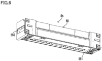
- the second supporting member 55 of the fixing unit 5b includes protrusion portions 551 that protrude from a lower surface of the second supporting member 55 (see Fig. 4 to Fig. 6 ).
- the first direction bias mechanism 8 includes a spring 80, a spring case 81, and a cap portion 82 (see Fig. 7 ).
- the spring case 81 houses the spring 80.
- the cap portion 82 is attached while being movable with respect to the spring case 81.
- the spring 80 is an example of the elastic member.
- the spring 80 is sandwiched between the cover member 102 and the second supporting member 55 of the fixing unit 5b.
- the spring 80 and the cap portion 82 are sandwiched between the cover member 102 and the second supporting member 55.
- the attachment direction D12 is a direction opposite to a drawing direction D11 of the fixing unit 5b.
- the fixing unit 5b is positioned in the first direction D1. It is noted that the first direction bias mechanism 8 may alternatively be attached to the second supporting member 55 of the fixing unit 5b.
- An image forming apparatus including:
Landscapes
- Physics & Mathematics (AREA)
- General Physics & Mathematics (AREA)
- Fixing For Electrophotography (AREA)
- Electrophotography Configuration And Component (AREA)
Abstract
A tilted surface (7a) is provided in a heating unit (5a) and is tilted with respect to a first direction. A movable member (71) includes a roller (71a) and is movable along the first direction. A first direction movement mechanism (73) causes the movable member (71) to move along the first direction in an interlocking manner with a movement of an operation member (103). When the movable member (71) moves in an interlocking manner with the movement of the operation member (103) in a first operation direction, the roller (71a) rolls on the tilted surface (7a) to cause the heating unit (5a) to move toward a second side against a bias force of a bias member (72). When the movable member (71) moves in the interlocking manner with the movement of the operation member (103) in a second operation direction, the roller (71a) rolls on the tilted surface (7a), and the bias member (72) causes the heating unit (5a) to move toward a first side.
Description
- This application is based upon and claims the benefit of priority from the corresponding
Japanese Patent Application No. 2023-217700 filed on December 25, 2023 - The present disclosure relates to an image forming apparatus including a fixing unit and a heating unit.
- An image forming apparatus that uses electrophotography fixes a toner image onto a sheet using a fixing device.
- The fixing device may be sectioned into a fixing unit which includes a fixing member and a pressure roller and a heating unit which includes a heater for heating the fixing member.
- Further, the image forming apparatus is known to include a mechanism for moving the heating unit from a heating position to an evacuation position in an interlocking manner with an operation with respect to an operation member. The fixing unit can be drawn out from a main body while the heating unit is evacuated to the evacuation position.
- An image forming apparatus according to an aspect of the present disclosure includes a main body in which an opening is formed, an operation member, a heating unit, a fixing unit, and an interlocking mechanism. The operation member is movable in a first operation direction or a second operation direction by being operated. The fixing unit includes a fixing member and a pressure member that biases a sheet toward the fixing member, is arranged inside the main body, and is capable of being drawn out along a first direction from the main body via the opening. The heating unit includes a heater that heats the fixing member, is arranged on a first side of a second direction that intersects with the first direction with respect to the fixing unit in the main body, and is movable along the second direction. The interlocking mechanism causes the heating unit to move along the second direction in an interlocking manner with a movement of the operation member. The interlocking mechanism includes a tilted surface, a bias member, a movable member, and a first direction movement mechanism. The tilted surface is provided in the heating unit while facing the first side and is tilted from a second side of the second direction toward the first side with respect to the first direction. The bias member biases the heating unit toward the first side. The movable member includes a roller that is supported rotatably and comes into contact with the tilted surface, and is movable along the first direction. The first direction movement mechanism causes the movable member to move along the first direction in the interlocking manner with the movement of the operation member. When the movable member moves in the interlocking manner with the movement of the operation member in the first operation direction, the roller rolls from a portion of the tilted surface on the second side to a portion thereof on the first side to cause the heating unit to move toward the second side against a bias force of the bias member. When the movable member moves in the interlocking manner with the movement of the operation member in the second operation direction, the roller rolls from the portion of the tilted surface on the first side to the portion thereof on the second side, and the bias member causes the heating unit to move toward the first side.
- This Summary is provided to introduce a selection of concepts in a simplified form that are further described below in the Detailed Description with reference where appropriate to the accompanying drawings. This Summary is not intended to identify key features or essential features of the claimed subject matter, nor is it intended to be used to limit the scope of the claimed subject matter. Furthermore, the claimed subject matter is not limited to implementations that solve any or all disadvantages noted in any part of this disclosure.
-
-
Fig. 1 is a configuration diagram of an image forming apparatus according to an embodiment; -
Fig. 2 is a diagram showing a partial configuration of a fixing device in the image forming apparatus according to the embodiment; -
Fig. 3 is a perspective view of a main body frame in the image forming apparatus according to the embodiment; -
Fig. 4 is a front view of the fixing device in a vicinity state in the image forming apparatus according to the embodiment; -
Fig. 5 is a front view of the fixing device in a spaced state in the image forming apparatus according to the embodiment; -
Fig. 6 is a perspective view of a fixing unit in the image forming apparatus according to the embodiment; -
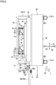
Fig. 7 is a plan view of the fixing device and an interlocking mechanism in a biased state in the image forming apparatus according to the embodiment; -
Fig. 8 is a plan view of the fixing device and the interlocking mechanism in a pulling state in the image forming apparatus according to the embodiment; and -
Fig. 9 is a perspective view in which a part of a movable member in the image forming apparatus according to the embodiment is omitted. - Hereinafter, an embodiment of the present disclosure will be described with reference to the drawings. It is noted that the following embodiment is an example of embodying the present disclosure and does not limit the technical scope of the present disclosure.
- An
image forming apparatus 10 according to the embodiment executes print processing using electrophotography. The print processing is processing of forming an image on asheet 900. - As shown in
Fig. 1 , theimage forming apparatus 10 includes asheet storing portion 2, asheet conveying device 3, and aprinting device 4. Thesheet conveying device 3 and theprinting device 4 are housed in amain body 1 as a housing. Themain body 1 includes amain body frame 1x that constitutes a framework of themain body 1 and an exterior member attached to themain body frame 1x. - The
sheet storing portion 2 is capable of storing a plurality ofsheets 900. Thesheet conveying device 3 includes asheet feed device 30 and a plurality ofconveying roller pairs 31. - The
sheet feed device 30 feeds thesheets 900 stored in thesheet storing portion 2 one by one to a conveying path 300. The conveying path 300 is a path of thesheets 900. - The plurality of
conveying roller pairs 31 convey thesheet 900 along the conveying path 300. One pair out of the plurality ofconveying roller pairs 31 discharges thesheet 900 on which an image has been formed onto adischarge tray 1a from the conveying path 300. - The
printing device 4 executes the print processing on thesheet 900 conveyed along the conveying path 300. The image to be formed on thesheet 900 is a toner image. - The
printing device 4 includes alaser scanning unit 40, one or moreimage forming portions 4x, atransfer device 45, and afixing device 5. Theimage forming portion 4x includes aphotoconductor 41, acharging device 42, a developingdevice 43, and adrum cleaning device 44. - The
charging device 42 charges a surface of thephotoconductor 41. Thelaser scanning unit 40 scans beam light on the charged surface of thephotoconductor 41. Thus, thelaser scanning unit 40 forms an electrostatic latent image on the surface of thephotoconductor 41. - By supplying toner to the surface of the
photoconductor 41, the developingdevice 43 develops the electrostatic latent image into a toner image. Thetransfer device 45 transfers the toner image that has been formed on the surface of thephotoconductor 41 onto thesheet 900. - The
transfer device 45 transfers the electrostatic latent image onto thesheet 900 at a transfer position P1 on the conveying path 300. - In the present embodiment, the
printing device 4 is a tandem-type color printing device that includes a plurality ofimage forming portions 4x. Further, thetransfer device 45 includes anintermediate transfer belt 450, a plurality ofprimary transfer devices 451, asecondary transfer device 452, and abelt cleaning device 453. - In the example shown in
Fig. 1 , theprinting device 4 includes fourimage forming portions 4x respectively corresponding to toner of four colors, that is, yellow, magenta, cyan, and black. Thetransfer device 45 includes fourprimary transfer devices 451 respectively corresponding to the fourimage forming portions 4x. - The
intermediate transfer belt 450 is rotatably supported by a plurality of supportingrollers 454. One of the plurality of supportingrollers 454 rotates by being driven by a belt drive device (not shown). Thus, theintermediate transfer belt 450 rotates. - Each of the
primary transfer devices 451 transfers the toner image formed on the surface of thephotoconductor 41 in the corresponding one of theimage forming portions 4x onto a surface of theintermediate transfer belt 450. Thus, a synthetic toner image obtained by synthesizing the toner images of four colors is formed on the surface of theintermediate transfer belt 450. - The
intermediate transfer belt 450 rotates while carrying the synthetic toner image. Thesecondary transfer device 452 transfers the synthetic toner image that has been formed on the surface of theintermediate transfer belt 450 onto thesheet 900 at the transfer position P1. - The
drum cleaning device 44 removes primary waste toner from the surface of thephotoconductor 41. The primary waste toner is toner remaining at a portion of the surface of thephotoconductor 41, that has passed through theprimary transfer device 451. - The
belt cleaning device 453 removes secondary waste toner from the surface of theintermediate transfer belt 450. The secondary waste toner is toner remaining at a portion of the surface of theintermediate transfer belt 450, that has passed through thesecondary transfer device 452. - The fixing
device 5 heats and pressurizes the synthetic toner image on thesheet 900 at a fixing position P2 on the conveying path 300. Thus, the fixingdevice 5 fixes the synthetic toner image onto thesheet 900. The fixing position P2 is a position on a downstream side of the transfer position P1 in a sheet conveying direction. - As shown in
Fig. 2 , the fixingdevice 5 includes aheater 51, a fixingbelt 52, a fixingroller 520, apressure roller 53, and asheet separation member 5200. - The fixing
belt 52 is a flexible cylindrical member including the fixingroller 520 therein. The fixingbelt 52 is heated by theheater 51. - The fixing
roller 520 is a cylindrical member which supports the fixingbelt 52 from an inner side of the fixingbelt 52. The fixingroller 520 is supported rotatably. The fixingbelt 52 is capable of rotating with the fixingroller 520. - The fixing
belt 52 includes a conductive base material, an elastic layer formed on an outer circumference of the base material, and a release layer formed on an outer circumference of the elastic layer. - The
heater 51 is arranged so as to oppose an outer circumferential surface of the fixingbelt 52. In the present embodiment, theheater 51 is a heating device that uses an induction heating system. Theheater 51 mainly heats the base material of the fixingbelt 52 by electromagnetic induction. - The
pressure roller 53 is supported rotatably. Thepressure roller 53 rotates by being driven by a drive device (not shown). The fixingbelt 52 and the fixingroller 520 rotate in conjunction with thepressure roller 53. - The fixing
belt 52 heats the toner image formed on thesheet 900. Thepressure roller 53 biases thesheet 900 toward the fixingbelt 52 to thus pressurize the toner image toward thesheet 900. - It is noted that the fixing
belt 52 is an example of a fixing member that is heated by theheater 51. Thepressure roller 53 is an example of a pressure member that biases thesheet 900 toward the fixingbelt 52. - The
sheet separation member 5200 peels thesheet 900 off from the fixingbelt 52 when thesheet 900 adheres onto the fixingbelt 52. - In the present embodiment, the fixing
device 5 is sectioned into aheating unit 5a and afixing unit 5b (seeFig. 4 and Fig. 5 ). Theheating unit 5a is arranged along a first direction D1 in themain body 1. The fixingunit 5b is also arranged along the first direction D1 in themain body 1. - In other words, the
heating unit 5a and the fixingunit 5b are arranged in a state where longitudinal directions thereof are provided along the first direction D1. - The
heating unit 5a and the fixingunit 5b are arranged next to each other in a second direction D2. In other words, the second direction D2 is an array direction of theheating unit 5a and the fixingunit 5b. The second direction D2 is a direction that intersects with the first direction D1. - In descriptions below, one side of the second direction D2 will be referred to as a first side D21, and the other side of the second direction D2 will be referred to as a second side D22 (see
Fig. 3 to Fig. 5 ,Fig. 7 , andFig. 8 ). Theheating unit 5a is arranged on the first side D21 with respect to the fixingunit 5b (seeFig. 4, Fig. 5 ,Fig. 7 , andFig. 8 ). - The
heating unit 5a includes theheater 51 and a first supportingmember 54. The fixingunit 5b includes the fixingbelt 52, the fixingroller 520, thepressure roller 53, and a second supportingmember 55. - The first supporting
member 54 is a member which supports theheater 51. The second supportingmember 55 is a member which supports the fixingbelt 52, the fixingroller 520, and thepressure roller 53. The fixingbelt 52 is supported by the second supportingmember 55 via the fixingroller 520. - The
main body frame 1x is configured by a combination of a plurality of metal pipes (seeFig. 3 ). Theheating unit 5a and the fixingunit 5b are supported by themain body frame 1x. The fixingunit 5b is arranged on the second side D22 of the second direction D2 with respect to theheating unit 5a. - The plurality of metal pipes configuring the
main body frame 1x includerestriction portions 11 and lower supporting portions 12 (seeFig. 3 to Fig. 5 ). - In the present embodiment, the
restriction portions 11 are two supporting column pipes that are formed to extend in a longitudinal direction D3 and are arranged while being spaced apart from each other in the first direction D1 (seeFig. 3 ). The longitudinal direction D3 is an up-down direction. - The lower supporting
portions 12 are two beam pipes that are formed to extend in the second direction D2 below theheating unit 5a and the fixingunit 5b and are arranged while being spaced apart from each other in the first direction D1 (seeFig. 3 ). - The
heating unit 5a and the fixingunit 5b are mounted on the lower supportingportions 12 in a state where longitudinal directions thereof are provided along the first direction D1 (seeFig. 7 andFig. 8 ). In other words, the lower supportingportions 12 support theheating unit 5a and the fixingunit 5b from below. - The
heating unit 5a and the fixingunit 5b are movable on the lower supportingportions 12 along the second direction D2. The fixingunit 5b is arranged between theheating unit 5a and the restriction portions 11 (seeFig. 4 and Fig. 5 ). - By the
heating unit 5a being moved to a position apart from the fixingunit 5b, the fixingunit 5b can be drawn out from themain body 1 along the first direction D1 (seeFig. 5 andFig. 8 ). - The
main body 1 is formed with an opening 101 (seeFig. 7 andFig. 8 ). Theopening 101 is a portion at which one end of the fixingunit 5b in the first direction D1 is opened to the outside of themain body 1. Theimage forming apparatus 10 includes acover member 102 that is capable of opening and closing the opening 101 (seeFig. 7 andFig. 8 ). - The
cover member 102 is supported by a first supportingshaft 102x. Thus, thecover member 102 is rotatable about the first supportingshaft 102x. Thecover member 102 is movable between a closing position at which theopening 101 is closed and an opening position at which theopening 101 is opened. -
Fig. 7 shows thecover member 102 positioned at the closing position and the fixingdevice 5.Fig. 8 shows thecover member 102 positioned at the opening position and the fixingdevice 5. - When the
cover member 102 is positioned at the closing position, thecover member 102 is retained at the closing position by a lock mechanism (not shown). By releasing the lock by the lock mechanism, thecover member 102 can rotate from the closing position to the opening position. - When the
cover member 102 is positioned at the opening position, the fixingunit 5b can be drawn out from themain body 1 via the opening 101 (seeFig. 8 ). - Meanwhile, it is favorable for the
heating unit 5a to be able to smoothly approach the fixingunit 5b or be spaced apart from the fixingunit 5b. Theimage forming apparatus 10 includes aninterlocking mechanism 7 for causing theheating unit 5a to smoothly approach the fixingunit 5b or be spaced apart from the fixingunit 5b (seeFig. 7 andFig. 8 ). - The
image forming apparatus 10 includes theinterlocking mechanism 7 and anoperation member 103 coupled to the interlocking mechanism 7 (seeFig. 7 andFig. 8 ). In the present embodiment, thecover member 102 doubles as theoperation member 103. - By being operated, the
operation member 103 is movable in a first operation direction or a second operation direction. - In the present embodiment, the first operation direction is a movement direction of the
cover member 102 when closing thecover member 102. The second operation direction is a movement direction of thecover member 102 when opening thecover member 102. - That is, the first operation direction is a direction in which the
cover member 102 moves when moving from the opening position to the closing position. The second operation direction is a direction in which thecover member 102 moves when moving from the closing position to the opening position. - The
interlocking mechanism 7 causes theheating unit 5a to move along the second direction D2 in an interlocking manner with the movement of theoperation member 103. - The
interlocking mechanism 7 causes theheating unit 5a to move toward the second side D22 in an interlocking manner with the movement of theoperation member 103 in the first operation direction (seeFig. 7 ). On the other hand, theinterlocking mechanism 7 causes theheating unit 5a to move toward the first side D21 in an interlocking manner with the movement of theoperation member 103 in the second operation direction (seeFig. 8 ). - The
interlocking mechanism 7 includes acoupling member 56, aguide member 70, amovable member 71,bias members 72, and a firstdirection movement mechanism 73. Thecoupling member 56 is coupled to the first supportingmember 54 of theheating unit 5a. Thecoupling member 56 configures a part of theheating unit 5a. - The
bias members 72 bias theheating unit 5a toward the first side D21. Specifically, thebias members 72 are one or more elastic members that bias theheating unit 5a toward the first side D21. For example, the elastic member is a coil spring, a leaf spring, or the like. - In the examples shown in
Fig. 7 andFig. 8 , thebias members 72 are two tension springs that elastically bias theheating unit 5a toward the first side D21. - The
coupling member 56 includes tiltedsurfaces 7a. The tilted surfaces 7a are provided in theheating unit 5a while facing the first side D21. The tilted surfaces 7a are surfaces that are tilted from the second side D22 toward the first side D21 with respect to the first direction D1. In the present embodiment, the tiltedsurfaces 7a are provided at two positions spaced apart from each other in the first direction D1 (seeFig. 7 andFig. 8 ). - The
movable member 71 is supported while being movable along the first direction D1. Theguide member 70 guides themovable member 71 along the first direction D1. For example, theguide member 70 is supported by themain body frame 1x. - The
movable member 71 includes one ormore rollers 71a that are supported rotatably (seeFig. 7 to Fig. 9 ). Therollers 71a are provided at positions respectively corresponding to the tiltedsurfaces 7a in themovable member 71. In the present embodiment, therollers 71a are provided at two positions spaced apart from each other in the first direction D1 (seeFig. 7 to Fig. 9 ). Therollers 71a roll while being in contact with the tiltedsurfaces 7a. - The first
direction movement mechanism 73 causes themovable member 71 to move along the first direction D1 in an interlocking manner with the movement of theoperation member 103. In the present embodiment, the firstdirection movement mechanism 73 is a link mechanism which converts the rotation of theoperation member 103 into a linear operation along the first direction D1. - The first
direction movement mechanism 73 includes afirst link member 731, asecond link member 732, and a third link member 733 (seeFig. 7 andFig. 8 ). - One end of the
first link member 731 is connected to themovable member 71, and the other end of thefirst link member 731 is coupled to one end of thesecond link member 732 by afirst coupling shaft 734. The other end of thesecond link member 732 is connected to one end of thethird link member 733 by asecond coupling shaft 735. The other end of thethird link member 733 is coupled to one end of theoperation member 103 by athird coupling shaft 737. - The
third link member 733 is rotatably supported by a second supportingshaft 736. - In the present embodiment, when moving the
operation member 103 from the opening position to the closing position, the firstdirection movement mechanism 73 causes themovable member 71 to move toward a rear side along the first direction D1. Moreover, when moving theoperation member 103 from the closing position to the opening position, the firstdirection movement mechanism 73 causes themovable member 71 to move toward a front side along the first direction D1. - As described above, the movement direction from the opening position to the closing position is the first operation direction. The movement direction from the closing position to the opening position is the second operation direction.
- In descriptions below, an end portion of the tilted
surface 7a on the second side D22 will be referred to as a base end portion of the tiltedsurface 7a, and an end portion of the tiltedsurface 7a on the first side D21 will be referred to as a terminal portion of the tiltedsurface 7a. The base end portion is an example of a portion of the tiltedsurface 7a on the second side D22. The terminal portion is an example of a portion of the tiltedsurface 7a on the first side D21. - When the
movable member 71 moves in an interlocking manner with the movement of theoperation member 103 in the first operation direction, theroller 71a rolls from the base end portion to the terminal portion on the tiltedsurface 7a. By rolling from the base end portion to the terminal portion on the tiltedsurface 7a, theroller 71a pushes the tiltedsurface 7a toward the second side D22. By pushing the tiltedsurface 7a toward the second side D22, theroller 71a causes theheating unit 5a to move toward the second side D22 against a bias force of thebias member 72. - Neither the
heating unit 5a nor the fixingunit 5b is fixed to themain body frame 1x by a fixture such as a screw. - The
restriction portions 11 restrict a movement range of the fixingunit 5b toward the second side D22. By therollers 71a causing theheating unit 5a to move toward the second side D22, the fixingunit 5b and theheating unit 5a are sandwiched by themovable member 71 and the restriction portions 11 (seeFig. 4 andFig. 7 ). -
Fig. 7 shows theinterlocking mechanism 7 in a biased state where themovable member 71 is biasing theheating unit 5a and the fixingunit 5b toward therestriction portions 11.Fig. 4 andFig. 7 each show the fixingdevice 5 in a vicinity state where theheating unit 5a is retained in the vicinity of the fixingunit 5b by theinterlocking mechanism 7. - By being sandwiched between the
movable member 71 and therestriction portions 11, the fixingunit 5b and theheating unit 5a are positioned in the second direction D2. - In other words, when the
movable member 71 moves in an interlocking manner with the movement of theoperation member 103 in the first operation direction, the fixingunit 5b and theheating unit 5a are sandwiched by themovable member 71 and therestriction portions 11 to thus be positioned in the second direction D2. - The first supporting
member 54 includes a plurality of concave firstfitting portions 542 that are opened toward the second side D22 (seeFig. 4 and Fig. 5 ). The second supportingmember 55 includes a plurality of convex secondfitting portions 553 into which the plurality of firstfitting portions 542 can be fit, respectively (seeFig. 4 and Fig. 5 ). - By the
interlocking mechanism 7 causing theheating unit 5a to move toward the second side D22, the plurality of firstfitting portions 542 and the plurality of secondfitting portions 553 fit into one another (seeFig. 4 ). - By the fitting of the plurality of first
fitting portions 542 and the plurality of secondfitting portions 553, relative movements of theheating unit 5a and the fixingunit 5b in the longitudinal direction D3 are restricted. - It is noted that alternatively, the second supporting
member 55 may include the plurality of firstfitting portions 542, and the first supportingmember 54 may include the plurality of secondfitting portions 553. - Meanwhile, when the
movable member 71 moves in an interlocking manner with the movement of theoperation member 103 in the second operation direction, theroller 71a rolls from the terminal portion to the base end portion on the tiltedsurface 7a, and thebias member 72 causes theheating unit 5a to move toward the first side D21. -
Fig. 8 shows theinterlocking mechanism 7 in a pulling state where thebias member 72 is pulling theheating unit 5a toward the first side D21.Fig. 5 andFig. 8 each show the fixingdevice 5 in a spaced state where theheating unit 5a is spaced apart from the fixingunit 5b toward the first side D21 by theinterlocking mechanism 7. - In the present embodiment, the
movable member 71 further includes first contact surfaces 71b (seeFig. 7 to Fig. 9 ). Thecoupling member 56 further includessecond contact surfaces 7b respectively corresponding to the first contact surfaces 71b and firstconcave portions 7c respectively corresponding to therollers 71a (seeFig. 7 andFig. 8 ). - The first contact surfaces 71b are surfaces that face the second side D22 and are capable of coming into contact with the second contact surfaces 7b of the
coupling member 56. For example, the first contact surfaces 71b are formed at three or more positions in themovable member 71. In the example shown inFig. 9 , the first contact surfaces 71b are formed at four positions in themovable member 71. - The second contact surfaces 7b are surfaces that face the first side D21 and are capable of coming into contact with the first contact surfaces 71b of the
movable member 71. The second contact surfaces 7b are formed at positions respectively corresponding to the first contact surfaces 71b in thecoupling member 56. - The first
concave portions 7c face the first side D21 and are each arranged next to the terminal portion of the tiltedsurface 7a in the first direction D1 (seeFig. 7 andFig. 8 ). The firstconcave portions 7c are provided at positions respectively corresponding to therollers 71a in thecoupling member 56. In the present embodiment, the firstconcave portions 7c are provided at two positions in thecoupling member 56. - A part of the
roller 71a can be inserted into the firstconcave portion 7c. Specifically, a part of theroller 71a including an edge on the second side D22 can be inserted into the firstconcave portion 7c. - When the
movable member 71 moves in an interlocking manner with the movement of theoperation member 103 in the first operation direction, the following first operation occurs. In the first operation, after theroller 71a rolls from the base end portion to the terminal portion on the tiltedsurface 7a, a part of theroller 71a enters the firstconcave portion 7c, and thefirst contact surface 71b is abutted against thesecond contact surface 7b (seeFig. 7 ). - By the first contact surfaces 71b being abutted against the
second contact surfaces 7b, the fixingunit 5b and theheating unit 5a are sandwiched by themovable member 71 and therestriction portions 11. Thus, the fixingunit 5b and theheating unit 5a are positioned in the second direction D2. - In general, an allowance is formed between the
roller 71a and a rotation shaft of theroller 71a. The fixingunit 5b and theheating unit 5a are positioned with high accuracy by being positioned in a state where the first contact surfaces 71b and the second contact surfaces 7b are in contact with one another. - Further, when the fixing
unit 5b and theheating unit 5a are positioned by the contact of the first contact surfaces 71b and thesecond contact surfaces 7b, a large force is not applied to therollers 71a. Therefore, durability of therollers 71a is improved. - On the other hand, when the
movable member 71 moves in an interlocking manner with the movement of theoperation member 103 in the second operation direction, the following second operation occurs. In the second operation, after therollers 71a are detached from the firstconcave portions 7c and the first contact surfaces 71b are spaced apart from thesecond contact surfaces 7b, therollers 71a each roll from the terminal portion to the base end portion on the tiltedsurface 7a (seeFig. 8 ). - In the present embodiment, the
coupling member 56 further includesthird contact surfaces 7d respectively corresponding to the first contact surfaces 71b and secondconcave portions 7e respectively corresponding to therollers 71a (seeFig. 7 andFig. 8 ). - The
third contact surfaces 7d are surfaces that face the first side D21 and are capable of coming into contact with the first contact surfaces 71b of themovable member 71. Thethird contact surfaces 7d are formed at positions respectively corresponding to the first contact surfaces 71b in thecoupling member 56. - The second
concave portions 7e face the first side D21 and are each arranged next to the base end portion of the tiltedsurface 7a in the first direction D1 (seeFig. 7 andFig. 8 ). The secondconcave portions 7e are provided at positions respectively corresponding to therollers 71a in thecoupling member 56. In the present embodiment, the secondconcave portions 7e are provided at two positions in thecoupling member 56. - A part of the
roller 71a can be inserted into the secondconcave portion 7e. Specifically, a part of theroller 71a including an edge on the second side D22 can be inserted into the secondconcave portion 7e. - When the
movable member 71 moves in an interlocking manner with the movement of theoperation member 103 in the second operation direction, the following third operation occurs. In the third operation, after theroller 71a is detached from the firstconcave portion 7c and further rolls from the terminal portion to the base end portion on the tiltedsurface 7a, a part of theroller 71a enters the secondconcave portion 7e, and thefirst contact surface 71b is abutted against thethird contact surface 7d (seeFig. 8 ). - Accordingly, when the
heating unit 5a is spaced apart from the fixingunit 5b toward the first side D21, a force of thebias member 72 is not applied to theroller 71a. Therefore, durability of therollers 71a is improved. - Meanwhile, when the
movable member 71 moves in an interlocking manner with the movement of theoperation member 103 in the first operation direction, the following fourth operation occurs. In the fourth operation, after theroller 71a is detached from the secondconcave portion 7e and thefirst contact surface 71b is spaced apart from thethird contact surface 7d, theroller 71a rolls from the base end portion to the terminal portion on the tiltedsurface 7a (seeFig. 7 ). - In the
image forming apparatus 10, theheating unit 5a can smoothly approach the fixingunit 5b or be spaced apart from the fixingunit 5b by actions of therollers 71a. - In the present embodiment, the
movable member 71 further includesrollers 71f (seeFig. 7 ). Therollers 71f are in contact with theguide member 70. When themovable member 71 moves along the first direction D1, therollers 71f roll on a surface of theguide member 70. - By actions of the
rollers 71f, theheating unit 5a can more smoothly approach the fixingunit 5b or be spaced apart from the fixingunit 5b. - In addition, the
image forming apparatus 10 further includes a firstdirection bias mechanism 8 that is attached to an inner surface of the cover member 102 (seeFig. 7 andFig. 8 ). Further, the second supportingmember 55 of the fixingunit 5b includesprotrusion portions 551 that protrude from a lower surface of the second supporting member 55 (seeFig. 4 to Fig. 6 ). - The first
direction bias mechanism 8 includes aspring 80, aspring case 81, and a cap portion 82 (seeFig. 7 ). - The
spring case 81 houses thespring 80. Thecap portion 82 is attached while being movable with respect to thespring case 81. Thespring 80 is an example of the elastic member. - When the
cover member 102 is positioned at the closing position, thespring 80 is sandwiched between thecover member 102 and the second supportingmember 55 of the fixingunit 5b. In the present embodiment, thespring 80 and thecap portion 82 are sandwiched between thecover member 102 and the second supportingmember 55. - By being sandwiched between the
cover member 102 and the second supportingmember 55, thespring 80 biases the second supportingmember 55 in an attachment direction D12 by the elastic force (seeFig. 7 ). The attachment direction D12 is a direction opposite to a drawing direction D11 of the fixingunit 5b. - Furthermore, by the force that the second supporting
member 55 receives from thespring 80 when thecover member 102 is positioned at the closing position, theprotrusion portions 551 are abutted against the lower supportingportions 12. - By the actions of the
spring 80 and theprotrusion portions 551, the fixingunit 5b is positioned in the first direction D1. It is noted that the firstdirection bias mechanism 8 may alternatively be attached to the second supportingmember 55 of the fixingunit 5b. - Hereinafter, a general outline of the disclosure extracted from the embodiment described above will be noted. It is noted that the respective configurations and processing functions described in the notes below can be sorted and arbitrarily combined as appropriate.
- An image forming apparatus, including:
- a main body in which an opening is formed;
- an operation member which is movable in a first operation direction or a second operation direction by being operated;
- a fixing unit which includes a fixing member and a pressure member that biases a sheet toward the fixing member, is arranged inside the main body, and is capable of being drawn out along a first direction from the main body via the opening;
- a heating unit which includes a heater that heats the fixing member, is arranged on a first side of a second direction that intersects with the first direction with respect to the fixing unit in the main body, and is movable along the second direction; and
- an interlocking mechanism which causes the heating unit to move along the second direction in an interlocking manner with a movement of the operation member, in which
- the interlocking mechanism includes
- a tilted surface which is provided in the heating unit while facing the first side and is tilted from a second side of the second direction toward the first side with respect to the first direction,
- a bias member which biases the heating unit toward the first side,
- a movable member which includes a roller that is supported rotatably and comes into contact with the tilted surface, and is movable along the first direction, and
- a first direction movement mechanism which causes the movable member to move along the first direction in the interlocking manner with the movement of the operation member,
- when the movable member moves in the interlocking manner with the movement of the operation member in the first operation direction, the roller rolls from a portion of the tilted surface on the second side to a portion thereof on the first side to cause the heating unit to move toward the second side against a bias force of the bias member, and
- when the movable member moves in the interlocking manner with the movement of the operation member in the second operation direction, the roller rolls from the portion of the tilted surface on the first side to the portion thereof on the second side, and the bias member causes the heating unit to move toward the first side.
- The image forming apparatus according to
note 1, in which - the movable member includes a first contact surface that faces the second side and is capable of coming into contact with a part of the heating unit,
- the heating unit includes
- a concave portion which faces the first side, is arranged next to an end portion of the tilted surface on the first side in the first direction, and into which a part of the roller can be inserted, and
- a second contact surface which faces the first side and is capable of coming into contact with the first contact surface,
- when the movable member moves in the interlocking manner with the movement of the operation member in the first operation direction, the part of the roller enters the concave portion and the first contact surface is abutted against the second contact surface after the roller rolls from the portion of the tilted surface on the second side to the portion thereof on the first side, and
- when the movable member moves in the interlocking manner with the movement of the operation member in the second operation direction, the roller rolls from the portion of the tilted surface on the first side to the portion thereof on the second side after the roller is detached from the concave portion and the first contact surface is spaced apart from the second contact surface.
- The image forming apparatus according to
note - the main body includes
- a lower supporting portion which supports the fixing unit and the heating unit from below, and
- a restriction portion which restricts a movement range of the fixing unit toward the second side, and
- when the movable member moves in the interlocking manner with the movement of the operation member in the first operation direction, the fixing unit and the heating unit are sandwiched by the restriction portion and the movable member to be positioned in the second direction.
- The image forming apparatus according to any one of
notes 1 to 3, including: - a cover member which is capable of opening and closing the opening and doubles as the operation member, in which
- the first operation direction is a movement direction of the cover member when closing the cover member, and
- the second operation direction is a movement direction of the cover member when opening the cover member.
- The image forming apparatus according to any one of
notes 1 to 4, in which
the heater is a heating device that uses an induction heating system. - It is to be understood that the embodiments herein are illustrative and not restrictive, since the scope of the disclosure is defined by the appended claims rather than by the description preceding them, and all changes that fall within metes and bounds of the claims, or equivalence of such metes and bounds thereof are therefore intended to be embraced by the claims.
Claims (5)
- An image forming apparatus (10), comprising:a main body (1) in which an opening (101) is formed;an operation member (103) which is movable in a first operation direction or a second operation direction by being operated;a fixing unit (5b) which includes a fixing member (52) and a pressure member (53) that biases a sheet toward the fixing member (52), is arranged inside the main body (1), and is capable of being drawn out along a first direction from the main body (1) via the opening (101);a heating unit (5a) which includes a heater (51) that heats the fixing member (52), is arranged on a first side of a second direction that intersects with the first direction with respect to the fixing unit (5b) in the main body (1), and is movable along the second direction; andan interlocking mechanism (7) which causes the heating unit (5a) to move along the second direction in an interlocking manner with a movement of the operation member (103), whereinthe interlocking mechanism (7) includesa tilted surface (7a) which is provided in the heating unit (5a) while facing the first side and is tilted from a second side of the second direction toward the first side with respect to the first direction,a bias member (72) which biases the heating unit (5a) toward the first side,a movable member (71) which includes a roller (71a) that is supported rotatably and comes into contact with the tilted surface (7a), and is movable along the first direction, anda first direction movement mechanism (73) which causes the movable member (71) to move along the first direction in the interlocking manner with the movement of the operation member (103),when the movable member (71) moves in the interlocking manner with the movement of the operation member (103) in the first operation direction, the roller (71a) rolls from a portion of the tilted surface (7a) on the second side to a portion thereof on the first side to cause the heating unit (5a) to move toward the second side against a bias force of the bias member (72), andwhen the movable member (71) moves in the interlocking manner with the movement of the operation member (103) in the second operation direction, the roller (71a) rolls from the portion of the tilted surface (7a) on the first side to the portion thereof on the second side, and the bias member (72) causes the heating unit (5a) to move toward the first side.
- The image forming apparatus (10) according to claim 1, whereinthe movable member (71) includes a first contact surface (71b) that faces the second side and is capable of coming into contact with a part of the heating unit (5a),the heating unit (5a) includesa concave portion (7c) which faces the first side, is arranged next to an end portion of the tilted surface (7a) on the first side in the first direction, and into which a part of the roller (71a) can be inserted, anda second contact surface (7b) which faces the first side and is capable of coming into contact with the first contact surface (71b),when the movable member (71) moves in the interlocking manner with the movement of the operation member (103) in the first operation direction, the part of the roller (71a) enters the concave portion (7c) and the first contact surface (71b) is abutted against the second contact surface (7b) after the roller (71a) rolls from the portion of the tilted surface (7a) on the second side to the portion thereof on the first side, andwhen the movable member (71) moves in the interlocking manner with the movement of the operation member (103) in the second operation direction, the roller (71a) rolls from the portion of the tilted surface (7a) on the first side to the portion thereof on the second side after the roller (71a) is detached from the concave portion (7c) and the first contact surface (71b) is spaced apart from the second contact surface (7b).
- The image forming apparatus (10) according to claim 1 or 2, whereinthe main body (1) includesa lower supporting portion (12) which supports the fixing unit (5b) and the heating unit (5a) from below, anda restriction portion (11) which restricts a movement range of the fixing unit (5b) toward the second side, andwhen the movable member (71) moves in the interlocking manner with the movement of the operation member (103) in the first operation direction, the fixing unit (5b) and the heating unit (5a) are sandwiched by the restriction portion (11) and the movable member (71) to be positioned in the second direction.
- The image forming apparatus (10) according to claim 1 or 2, comprising:a cover member (102) which is capable of opening and closing the opening (101) and doubles as the operation member (103), whereinthe first operation direction is a movement direction of the cover member (102) when closing the cover member (102), andthe second operation direction is a movement direction of the cover member (102) when opening the cover member (102).
- The image forming apparatus (10) according to claim 1 or 2, wherein
the heater (51) is a heating device that uses an induction heating system.
Applications Claiming Priority (1)
| Application Number | Priority Date | Filing Date | Title |
|---|---|---|---|
| JP2023217700A JP2025101102A (en) | 2023-12-25 | 2023-12-25 | Image forming device |
Publications (1)
| Publication Number | Publication Date |
|---|---|
| EP4579357A1 true EP4579357A1 (en) | 2025-07-02 |
Family
ID=93925942
Family Applications (1)
| Application Number | Title | Priority Date | Filing Date |
|---|---|---|---|
| EP24221587.9A Pending EP4579357A1 (en) | 2023-12-25 | 2024-12-19 | Image forming apparatus |
Country Status (3)
| Country | Link |
|---|---|
| US (1) | US12547106B2 (en) |
| EP (1) | EP4579357A1 (en) |
| JP (1) | JP2025101102A (en) |
Citations (3)
| Publication number | Priority date | Publication date | Assignee | Title |
|---|---|---|---|---|
| US4760411A (en) * | 1985-08-06 | 1988-07-26 | Konishiroku Photo Industry Co., Ltd. | Electrostatic recording apparatus |
| US20210165352A1 (en) * | 2019-11-29 | 2021-06-03 | Kyocera Document Solutions Inc. | Image forming apparatus |
| US20230288853A1 (en) * | 2022-03-10 | 2023-09-14 | Kyocera Document Solutions Inc. | Image forming apparatus |
Family Cites Families (4)
| Publication number | Priority date | Publication date | Assignee | Title |
|---|---|---|---|---|
| JP4841179B2 (en) * | 2005-06-17 | 2011-12-21 | 株式会社リコー | Fixing apparatus and image forming apparatus |
| JP5263147B2 (en) * | 2009-12-28 | 2013-08-14 | ブラザー工業株式会社 | Fixing device |
| JP6485748B2 (en) * | 2015-07-27 | 2019-03-20 | 富士ゼロックス株式会社 | Image forming apparatus and fixing device |
| JP2017194584A (en) * | 2016-04-21 | 2017-10-26 | 京セラドキュメントソリューションズ株式会社 | Image forming apparatus |
-
2023
- 2023-12-25 JP JP2023217700A patent/JP2025101102A/en active Pending
-
2024
- 2024-12-19 EP EP24221587.9A patent/EP4579357A1/en active Pending
- 2024-12-23 US US19/000,099 patent/US12547106B2/en active Active
Patent Citations (3)
| Publication number | Priority date | Publication date | Assignee | Title |
|---|---|---|---|---|
| US4760411A (en) * | 1985-08-06 | 1988-07-26 | Konishiroku Photo Industry Co., Ltd. | Electrostatic recording apparatus |
| US20210165352A1 (en) * | 2019-11-29 | 2021-06-03 | Kyocera Document Solutions Inc. | Image forming apparatus |
| US20230288853A1 (en) * | 2022-03-10 | 2023-09-14 | Kyocera Document Solutions Inc. | Image forming apparatus |
Also Published As
| Publication number | Publication date |
|---|---|
| US20250208549A1 (en) | 2025-06-26 |
| US12547106B2 (en) | 2026-02-10 |
| JP2025101102A (en) | 2025-07-07 |
Similar Documents
| Publication | Publication Date | Title |
|---|---|---|
| US11966180B2 (en) | Image forming apparatus with action member for moving heating unit from reference position to evacuation position | |
| JP6288320B2 (en) | Image forming apparatus | |
| US12019386B2 (en) | Image forming apparatus with heating unit rockable between reference attitude and tilted attitude | |
| US11803140B2 (en) | Image forming apparatus | |
| US9182719B2 (en) | Moving device assembly and image forming apparatus including the moving device assembly | |
| US8971762B2 (en) | Image forming apparatus | |
| US12019383B2 (en) | Image forming apparatus including reciprocatable fixing unit next to heating unit | |
| EP4579358A1 (en) | Image forming apparatus | |
| US12111610B2 (en) | Image forming apparatus having improved mountability of a cartridge while conserving space | |
| US20210132537A1 (en) | Sheet conveying apparatus and image forming apparatus | |
| US12386288B2 (en) | Image forming apparatus capable of stabilizing electrical connection between movable unit and support unit included in fixing device | |
| US10046931B2 (en) | Sheet conveying apparatus, image forming apparatus, and image reading apparatus | |
| US12547106B2 (en) | Image forming apparatus | |
| JP2020086311A (en) | Image forming apparatus | |
| KR20190013350A (en) | Image forming apparatus | |
| US12353162B2 (en) | Drum cartridge having separation shaft for moving developing frame away from photosensitive drum | |
| US11835914B2 (en) | Apparatus having a replaceable cover | |
| EP4703810A1 (en) | Image forming apparatus | |
| US11849089B1 (en) | Image forming apparatus | |
| CN215264384U (en) | image forming apparatus | |
| US20260110984A1 (en) | Image forming apparatus | |
| JP2026050597A (en) | Image forming system |
Legal Events
| Date | Code | Title | Description |
|---|---|---|---|
| PUAI | Public reference made under article 153(3) epc to a published international application that has entered the european phase |
Free format text: ORIGINAL CODE: 0009012 |
|
| STAA | Information on the status of an ep patent application or granted ep patent |
Free format text: STATUS: THE APPLICATION HAS BEEN PUBLISHED |
|
| AK | Designated contracting states |
Kind code of ref document: A1 Designated state(s): AL AT BE BG CH CY CZ DE DK EE ES FI FR GB GR HR HU IE IS IT LI LT LU LV MC ME MK MT NL NO PL PT RO RS SE SI SK SM TR |
|
| STAA | Information on the status of an ep patent application or granted ep patent |
Free format text: STATUS: REQUEST FOR EXAMINATION WAS MADE |
|
| 17P | Request for examination filed |
Effective date: 20250922 |