EP4579311A1 - Light deflector - Google Patents
Light deflector Download PDFInfo
- Publication number
- EP4579311A1 EP4579311A1 EP23879525.6A EP23879525A EP4579311A1 EP 4579311 A1 EP4579311 A1 EP 4579311A1 EP 23879525 A EP23879525 A EP 23879525A EP 4579311 A1 EP4579311 A1 EP 4579311A1
- Authority
- EP
- European Patent Office
- Prior art keywords
- view
- torsion bar
- rotation axis
- side edge
- width
- Prior art date
- Legal status (The legal status is an assumption and is not a legal conclusion. Google has not performed a legal analysis and makes no representation as to the accuracy of the status listed.)
- Pending
Links
Images



Classifications
-
- B—PERFORMING OPERATIONS; TRANSPORTING
- B81—MICROSTRUCTURAL TECHNOLOGY
- B81B—MICROSTRUCTURAL DEVICES OR SYSTEMS, e.g. MICROMECHANICAL DEVICES
- B81B3/00—Devices comprising flexible or deformable elements, e.g. comprising elastic tongues or membranes
- B81B3/0035—Constitution or structural means for controlling the movement of the flexible or deformable elements
- B81B3/004—Angular deflection
- B81B3/0048—Constitution or structural means for controlling angular deflection not provided for in groups B81B3/0043 - B81B3/0045
-
- G—PHYSICS
- G02—OPTICS
- G02B—OPTICAL ELEMENTS, SYSTEMS OR APPARATUS
- G02B26/00—Optical devices or arrangements for the control of light using movable or deformable optical elements
- G02B26/08—Optical devices or arrangements for the control of light using movable or deformable optical elements for controlling the direction of light
- G02B26/0816—Optical devices or arrangements for the control of light using movable or deformable optical elements for controlling the direction of light by means of one or more reflecting elements
- G02B26/0833—Optical devices or arrangements for the control of light using movable or deformable optical elements for controlling the direction of light by means of one or more reflecting elements the reflecting element being a micromechanical device, e.g. a MEMS mirror, DMD
- G02B26/0858—Optical devices or arrangements for the control of light using movable or deformable optical elements for controlling the direction of light by means of one or more reflecting elements the reflecting element being a micromechanical device, e.g. a MEMS mirror, DMD the reflecting means being moved or deformed by piezoelectric means
-
- B—PERFORMING OPERATIONS; TRANSPORTING
- B81—MICROSTRUCTURAL TECHNOLOGY
- B81B—MICROSTRUCTURAL DEVICES OR SYSTEMS, e.g. MICROMECHANICAL DEVICES
- B81B3/00—Devices comprising flexible or deformable elements, e.g. comprising elastic tongues or membranes
- B81B3/0035—Constitution or structural means for controlling the movement of the flexible or deformable elements
- B81B3/004—Angular deflection
- B81B3/0043—Increasing angular deflection
-
- G—PHYSICS
- G02—OPTICS
- G02B—OPTICAL ELEMENTS, SYSTEMS OR APPARATUS
- G02B26/00—Optical devices or arrangements for the control of light using movable or deformable optical elements
- G02B26/08—Optical devices or arrangements for the control of light using movable or deformable optical elements for controlling the direction of light
- G02B26/10—Scanning systems
- G02B26/105—Scanning systems with one or more pivoting mirrors or galvano-mirrors
-
- H—ELECTRICITY
- H10—SEMICONDUCTOR DEVICES; ELECTRIC SOLID-STATE DEVICES NOT OTHERWISE PROVIDED FOR
- H10N—ELECTRIC SOLID-STATE DEVICES NOT OTHERWISE PROVIDED FOR
- H10N30/00—Piezoelectric or electrostrictive devices
- H10N30/20—Piezoelectric or electrostrictive devices with electrical input and mechanical output, e.g. functioning as actuators or vibrators
- H10N30/204—Piezoelectric or electrostrictive devices with electrical input and mechanical output, e.g. functioning as actuators or vibrators using bending displacement, e.g. unimorph, bimorph or multimorph cantilever or membrane benders
- H10N30/2041—Beam type
-
- B—PERFORMING OPERATIONS; TRANSPORTING
- B81—MICROSTRUCTURAL TECHNOLOGY
- B81B—MICROSTRUCTURAL DEVICES OR SYSTEMS, e.g. MICROMECHANICAL DEVICES
- B81B2201/00—Specific applications of microelectromechanical systems
- B81B2201/04—Optical MEMS
- B81B2201/042—Micromirrors, not used as optical switches
-
- B—PERFORMING OPERATIONS; TRANSPORTING
- B81—MICROSTRUCTURAL TECHNOLOGY
- B81B—MICROSTRUCTURAL DEVICES OR SYSTEMS, e.g. MICROMECHANICAL DEVICES
- B81B2203/00—Basic microelectromechanical structures
- B81B2203/01—Suspended structures, i.e. structures allowing a movement
- B81B2203/0145—Flexible holders
- B81B2203/0154—Torsion bars
-
- B—PERFORMING OPERATIONS; TRANSPORTING
- B81—MICROSTRUCTURAL TECHNOLOGY
- B81B—MICROSTRUCTURAL DEVICES OR SYSTEMS, e.g. MICROMECHANICAL DEVICES
- B81B2203/00—Basic microelectromechanical structures
- B81B2203/05—Type of movement
- B81B2203/058—Rotation out of a plane parallel to the substrate
Definitions
- the present invention relates to a light deflector that is equipped in a scanning device and emits scanning light.
- a light deflector manufactured as a micro electro mechanical systems (MEMS) device reflects an incident laser beam onto a mirror portion that reciprocally rotates around a rotation axis, and emits reflected light as scanning light from the mirror portion (for example, Patent Literatures 1 to 3).
- MEMS micro electro mechanical systems
- the light deflector of Patent Literature 1 includes a mirror portion, a pair of torsion bars that are provided one on each side of the mirror portion in an extending direction of a rotation axis of the mirror portion and that extend from the mirror portion along the rotation axis, and a piezoelectric actuator that is coupled to a distal end-side end portion of each torsion bar and reciprocally rotates the torsion bar around the rotation axis.
- the light deflector of Patent Literature 2 includes a mirror portion, four torsion bars in total of which two are provided on each side of the mirror portion in an extending direction of a rotation axis of the mirror portion, and which extend parallel to each other along the rotation axis with gaps having an equal width interposed therebetween, and a piezoelectric actuator that is coupled to a distal end-side end portion of each of the torsion bars to reciprocally rotate the torsion bar around the rotation axis.
- the light deflector of Patent Literature 3 includes a mirror portion, four torsion bars in total of which two are provided on each side of the mirror portion in an extending direction of a rotation, respectively, and which are hole-machined (that is, in a tapered shape) such that a gap between the two torsion bars is narrowed toward a distal end side that is largely separated, and an electrostatic actuator that reciprocally rotates the mirror portion around the rotation axis from both sides in a direction perpendicular to the rotation axis.
- a ratio of a width of the torsion bar to a thickness of the torsion bar in the front view is defined as an aspect ratio (A.R.).
- a location where the maximum stress is generated in the torsion bar that is, a location that is most likely to be damaged as the torsion bar reciprocally rotates, is a location on the rotation axis in the front view of the torsion bar when A.R. > 1.
- A.R. ⁇ 1 a corner portion is provided as a portion farthest from the rotation axis in a cross section of the torsion bar.
- the light deflector of Patent Literature 1 is A.R. ⁇ 1, and locations of the maximum stress of the mirror portion are four corners of the cross section of the mirror portion.
- the only solution is to narrow the width of the torsion bar or to reduce the thickness thereof.
- the decrease in the width and the thickness of the torsion bar increases harmonics generated in the mirror portion, which causes abnormal oscillation (oscillation in the extending direction of the rotation axis or in a perpendicular direction to the rotation axis, or the like) in the mirror portion.
- Patent Literature 2 since the two torsion bars on each side with respect to the mirror portion are completely opened by a gap extending in the width direction at an end on a side opposite to the mirror portion, a transmission efficiency of a rotation force transmitted from the piezoelectric actuator to the torsion bar is lowered.
- the slits are formed in the torsion bars such that both ends in the extending direction are closed in the front view and the slits extend along the rotation axis over length range that reaches the inner coupling region and the outer coupling region at both ends. Accordingly, the stress applied to each torsion bar during the reciprocating rotation around the rotation axis is dispersed to four of the side surfaces of the torsion bar and the inner surfaces of the slit. Therefore, the reciprocating rotation angle when the maximum allowable stress is generated in the torsion bar can be increased.
- FIG. 3A is a front view of a range including the mirror portion 11 and the inner end portions of the torsion bars 12a and 12b in the extending direction of the rotation axis Da.
- FIG. 3B is a view illustrating an enlarged portion of the inner coupling region 38.
- the inner expansion end portion 24c has the same columnar hole shape (another example of the second curved contour shape) as the outer expansion end portion 24a, and is formed to penetrate the mirror portion 11 with left-right symmetrical with respect to the rotation axis Da in the inner coupling region 38.
- a boundary portion between the equal-width extension portion 22 and the inner expansion end portion 24c is set to a contour line extending in parallel with the second curve line.
- the diameter of the inner expansion end portion 24c is larger than the width of the equal-width extension portion 22, and the inner expansion end portion 24c is wider than the equal-width extension portion 22 in the width direction of the slit 20a.
- the curve-shaped outer corner portions 30a and 30b have significance of reinforcement against the expansion of the inner expansion end portion 24c in the width direction.
- FIG. 4 is a cross-sectional view which is cut in the thickness direction of the light deflector 10 along the axis Ax of FIG. 1 in a stationary state of the mirror portion 11, and
- FIG. 5 is a cross-sectional view which is cut along a plane parallel to the cross section of FIG. 4 at the position of the equal-width extension portion 22 of the torsion bar 12a.
- an SOI substrate 50 has a laminated structure of five layers of an oxide film layer 51, an active layer 52, an oxide film layer 53, a handling layer 54, and an oxide film layer 55 in this order from the top.
- the oxide film layers 51, 53, and 55 contain SiO 2 as a component.
- the active layer 52 and the handling layer 54 contain Si as a component.
- a piezoelectric element 58 has a laminated structure of three layers of an upper electrode layer 59, a lead zirconate titanate (PZT) film layer 60, and a lower electrode layer 61 in this order from the top.
- the equal-width extension portion 22 of the slit 20a penetrates the torsion bar 12a in the thickness direction.
- the outer expansion end portion 24a and the inner expansion end portion 24b of the slit 20a also penetrate the outer expansion end portion 24a of the torsion bar 12a and the inner expansion end portion 24b of the mirror portion 11 in the thickness direction, similarly to the equal-width extension portion 22.
- the slit 20a in the torsion bar 12a is manufactured by deep reactive ion etching (deep RIE).
- deep RIE deep reactive ion etching
- the upper electrode layer 59 and the PZT film layer 60 on the upper side in the three-layer laminate of the piezoelectric element 58 are removed by etching, and only the lowermost lower electrode layer 61 remains without being removed.
- the lower electrode layer 61 is a layer of an earth voltage, and as a result of the residual lower electrode layer 61 in the outer coupling region 36, the lower electrode layers 61 of the left and right inner actuators 13a and 13b are in a state of electrically connected to each other in the outer coupling region 36.
- the left and right inner actuators 13a and 13b are separated from each other in the outer coupling region 36 in the upper electrode layer 59 and the PZT film layer 60, the left and right inner actuators 13a and 13b are individually supplied with a drive voltage and can be driven individually.
- FIG. 6 is a description view of an aspect ratio A.R. of the torsion bar 12a.
- the definitions of the respective reference numerals are as follows.
- the setting is performed as in the following Expression (2). Wa ⁇ Wb / Ta ⁇ 1
- the significance of Expression (5) is that, although the slits 20a and 20b are originally formed to prevent damage to the corners of the cross section of the torsion bars 12a and 12b, when Wa/Ta ⁇ 1, damage may occur earlier on the rotation axis of the torsion bars 12a and 12b, and thus the significance of the formation of the slits 20a and 20b may be lost.
- the significance of Expression (6) is that, when Wb > 2 ⁇ Wc is satisfied, the shake (pumping) of the mirror portion 11 in the extending direction of the rotation axis Da is dominant. In addition, it is advantageous that Wb is 25 ⁇ m or more.
- the two torsion bars facing each other in the width direction in Patent Literature 3 are not referred to as slits according to the present invention because the holes of a tapered shape are formed and the torsion bars are too far apart from each other, but are included in Wb > 2 ⁇ Wc in terms of numerical expression. Therefore, the rotation drive force of the torsion bar or the inversion drive force for reversing the rotation is increased, and the load of the actuator is increased.
- torsion bar 12 (general term for the torsion bars 12a and 12b) will be described. First, the effects of the configuration in which the slit 20 has only the intermediate equal-width extension portion 22 without the outer expansion end portion 24a and the inner expansion end portion 24b at both ends will be described.
- the unit rotation angle (unit deflection angle: Mpa/deg) of the torsion bar 12 around the rotation axis Da was reduced by 25% due to the stress dispersion effect of the inner surface of the slit 20. This means that a limit deflection angle of the torsion bar 12 around the rotation axis Da is 1.33 times.
- FIG. 7 is a stress distribution view around the slit 20a when the slits 20a and 20b of the light deflector 10 are configured of only the equal-width extension portion 22 without having the outer expansion end portion 24a and the inner expansion end portions 24b and 24c.
- FIG. 7 illustrates a screen display based on an analysis result of a simulation, and illustrates that the stress increases from a dark portion to a light portion.
- the outer expansion end portion 24a and the inner expansion end portion 24b, or the inner expansion end portion 24c are consecutively provided respectively at both ends of the equal-width extension portion 22 such that the maximum stress in the torsion bars 12a and 12b is equal to or less than a predetermined upper limit.
- the stress transmitted from the mirror portion 11 in the outside direction along the rotation axis Da in the torsion bars 12a and 12b is divided into left and right portions of the torsion bars 12a and 12b on both sides of the slit 20 in the width direction and is transmitted in parallel with the outer coupling region 36.
- the circular shape of the outer expansion end portion 24a in the front view has an effect of appropriately dispersing in the left and right the stress that is divided into the left and right, and transmitted in parallel, thereby homogenizing the stress in the outer coupling region 36 and reducing the maximum stress.
- the reduction in the maximum stress leads to an increase in a maximum allowable reciprocation angle of the mirror portion 11 around the rotation axis Da.
- the effects of the inner expansion end portion 24c will be described before the inner expansion end portion 24b.
- the effects of the inner expansion end portion 24c are the same as the effects of the outer expansion end portion 24a. That is, in the mirror portion 11, the stress transmitted from the torsion bars 12a and 12b in the inner direction along the rotation axis Da is divided into left and right portions of the torsion bars 12a and 12b on both sides of the slit 20 in the width direction and is transmitted in parallel with the mirror portion 11.
- the circular shape of the inner expansion end portion 24c in the front view has an effect of appropriately dispersing in the left and right the stress that is divided into the left and right, and transmitted in parallel, thereby homogenizing the stress in the inner coupling region 38 and reducing the maximum stress, similarly to the outer expansion end portion 24a. Since the inner expansion end portion 24c has a simpler shape than the inner expansion end portion 24b, there is an advantage that the manufacturing cost is low.
- the inner end of the inner expansion end portion 24b is located outside the inner end of the inner expansion end portion 24c in the extending direction of the rotation axis Da. This means that the entire surface of the mirror portion 11 of which the beam cross section of the incidence light La is a substantially circular shape is irradiated.
- the closest point to the center O is deeply penetrated into the center O in the mirror portion 11. This means that an effective diameter of the mirror portion 11 in the extending direction of the rotation axis Da is reduced, which causes a decrease in resolution of an image generated by the scanning light Lb in an irradiation region such as a screen.
- the inner expansion end portion 24b is formed along a circumference contour of the mirror portion 11, and the closest point to the center O can be sufficiently separated from the inner expansion end portion 24c. Therefore, the torsion bar 12a relaxes the stress at the inner ends of the torsion bars 12a and 12b while minimizing the decrease in the effective diameter of the mirror portion 11. Accordingly, it is possible to increase the reciprocating rotation angle of the mirror portion 11 around the rotation axis Da while avoiding the decrease in the effective diameter of the mirror portion 11.
- the torsion bars 12a and 12b in which the slits 20a and 20b are formed on the inner peripheral side are not separated into two respectively, and maintain one torsion bar, and the light deflector 10 is configured to include only one torsion bar on each side of the mirror portion 11.
- the light deflector 10 is a biaxial scanning type light deflector.
- the light deflector of the present invention may be a uniaxial scanning type light deflector as long as the actuator includes a configuration of reciprocally rotating the mirror portion around the rotation axis through the torsion bar.
- the equal-width extension portion 22 is described as having an equal width, but in the present invention, the extension portion of the formation location of the equal-width extension portion 22 of the light deflector 10 may not be the equal-width extension portion over the entire length in a front view.
- the both ends of the extension portion may have the same width in a front view to the extent that the driving force of the inner actuators 13a and 13b does not significantly increase, the width of the middle portion may be widened or narrowed, and the widths of the both ends of the extension portion may be different from each other.
Landscapes
- Physics & Mathematics (AREA)
- General Physics & Mathematics (AREA)
- Optics & Photonics (AREA)
- Engineering & Computer Science (AREA)
- Computer Hardware Design (AREA)
- Microelectronics & Electronic Packaging (AREA)
- Mechanical Optical Scanning Systems (AREA)
- Micromachines (AREA)
- Mechanical Light Control Or Optical Switches (AREA)
Abstract
Description
- The present invention relates to a light deflector that is equipped in a scanning device and emits scanning light.
- A light deflector manufactured as a micro electro mechanical systems (MEMS) device reflects an incident laser beam onto a mirror portion that reciprocally rotates around a rotation axis, and emits reflected light as scanning light from the mirror portion (for example, Patent Literatures 1 to 3).
- The light deflector of Patent Literature 1 includes a mirror portion, a pair of torsion bars that are provided one on each side of the mirror portion in an extending direction of a rotation axis of the mirror portion and that extend from the mirror portion along the rotation axis, and a piezoelectric actuator that is coupled to a distal end-side end portion of each torsion bar and reciprocally rotates the torsion bar around the rotation axis.
- The light deflector of Patent Literature 2 includes a mirror portion, four torsion bars in total of which two are provided on each side of the mirror portion in an extending direction of a rotation axis of the mirror portion, and which extend parallel to each other along the rotation axis with gaps having an equal width interposed therebetween, and a piezoelectric actuator that is coupled to a distal end-side end portion of each of the torsion bars to reciprocally rotate the torsion bar around the rotation axis.
- The light deflector of Patent Literature 3 includes a mirror portion, four torsion bars in total of which two are provided on each side of the mirror portion in an extending direction of a rotation, respectively, and which are hole-machined (that is, in a tapered shape) such that a gap between the two torsion bars is narrowed toward a distal end side that is largely separated, and an electrostatic actuator that reciprocally rotates the mirror portion around the rotation axis from both sides in a direction perpendicular to the rotation axis.
-
- Patent Literature 1:
Japanese Patent Application Laid-Open No. 2009-169290 - Patent Literature 2:
Japanese Patent Application Laid-Open No. 2016-151681 - Patent Literature 3:
Japanese Patent No. 3905539 - It is desirable that the light deflector has a large scanning angle corresponding to a reciprocating rotation angle of the mirror portion around the rotation axis. On the other hand, a maximum reciprocating rotation angle of the mirror portion is limited by a maximum allowable stress of the torsion bar so that the torsion bar is not damaged during the reciprocating rotation.
- When a direction view of the mirror portion as viewed from a thickness direction is defined as a front view, a ratio of a width of the torsion bar to a thickness of the torsion bar in the front view is defined as an aspect ratio (A.R.). A location where the maximum stress is generated in the torsion bar, that is, a location that is most likely to be damaged as the torsion bar reciprocally rotates, is a location on the rotation axis in the front view of the torsion bar when A.R. > 1. In addition, when A.R. < 1, a corner portion is provided as a portion farthest from the rotation axis in a cross section of the torsion bar.
- The light deflector of Patent Literature 1 is A.R. < 1, and locations of the maximum stress of the mirror portion are four corners of the cross section of the mirror portion. In order to increase the maximum reciprocating rotation angle of the mirror portion with this structure, the only solution is to narrow the width of the torsion bar or to reduce the thickness thereof. The decrease in the width and the thickness of the torsion bar increases harmonics generated in the mirror portion, which causes abnormal oscillation (oscillation in the extending direction of the rotation axis or in a perpendicular direction to the rotation axis, or the like) in the mirror portion.
- In Patent Literature 2, since the two torsion bars on each side with respect to the mirror portion are completely opened by a gap extending in the width direction at an end on a side opposite to the mirror portion, a transmission efficiency of a rotation force transmitted from the piezoelectric actuator to the torsion bar is lowered.
- In the light deflector of Patent Literature 3, since coupling points where the two torsion bars on each side of the mirror portion are coupled to the mirror portion are two coupling points separated from each other with respect to the rotation axis in the perpendicular direction, a rotation drive force of the torsion bars or an inversion drive force for reversing the rotation is increased, and a load of the actuator is increased, as compared with a case of one coupling point.
- An object of the present invention is to provide a light deflector that can increase a maximum allowable rotation angle of a torsion bar by overcoming the above-described problem of the related technique in a case where an aspect ratio A.R. of the torsion bar is A.R. < 1.
- Alight deflector of the present invention including:
- a mirror portion having a mirror surface on one side in a thickness direction and configured to reciprocally rotate around a rotation axis (Da) perpendicular to the thickness direction;
- a pair of torsion bars configured to extend along the rotation axis from inner coupling positions of both ends of the mirror portion in an extending direction of the rotation axis;
- actuators coupling to the torsion bars from both sides in a width direction at an outer coupling position apart from the inner coupling position in the extending direction and reciprocally rotating the torsion bars around the rotation axis at the outer coupling position; and
- slits formed in the torsion bars such that both ends in the extending direction are closed in a front view as a direction view when the mirror surface is viewed from the one side in the thickness direction and the slits extend along the rotation axis in a length range in which the both ends reach the inner coupling position and the outer coupling position, in which
- a dimension of the torsion bar between both ends in the front view is Wa, and a thickness in the front view is Ta,
- a width of the slit in the front view is Wb, and
- (Wa - Wb)/Ta < 1 is satisfied.
- According to the present invention, in the light deflector in which an aspect ratio A.R. of the torsion bar is A.R. < 1, the slits are formed in the torsion bars such that both ends in the extending direction are closed in the front view and the slits extend along the rotation axis over length range that reaches the inner coupling region and the outer coupling region at both ends. Accordingly, the stress applied to each torsion bar during the reciprocating rotation around the rotation axis is dispersed to four of the side surfaces of the torsion bar and the inner surfaces of the slit. Therefore, the reciprocating rotation angle when the maximum allowable stress is generated in the torsion bar can be increased.
-
-
FIG. 1 is a schematic view of a light deflector as viewed from an oblique front side of a front surface. -
FIG. 2A is an enlarged front view of a range including a torsion bar and a periphery thereof inFIG. 1 . -
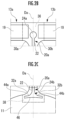
FIG. 2B is an enlarged view of a range of an outer coupling region ofFIG. 2A . -
FIG. 2C is an enlarged view of a range of an inner coupling region ofFIG. 2A . -
FIG. 3A is a front view illustrating a range in which an inner expansion portion having a shape different from an inner expansion portion ofFIG. 2A is provided, together with inner end portions of the torsion bars on both sides thereof. -
FIG. 3B is an enlarged view of the inner coupling region ofFIG. 3A . -
FIG. 4 is a cross-sectional view which is cut in a thickness direction of the light deflector along an axis Ax ofFIG. 1 in a stationary state of the mirror portion. -
FIG. 5 is a cross-sectional view which is cut along a plane parallel to the cross section ofFIG. 4 at a position of an equal-width extension portion of the torsion bar. -
FIG. 6 is a description view of an aspect ratio of the torsion bar. -
FIG. 7 is a stress distribution view around a slit when the slit is configured of only the equal-width extension portion. - Hereinafter, embodiments of the present invention will be described. The present invention includes various modified configurations of the embodiments within the range of design matters of those skilled in the art. Configuration elements common to a plurality of embodiments are denoted by the same reference numerals throughout all the drawings.
-
FIG. 1 is a schematic view of alight deflector 10 as viewed from an oblique front side of a front surface. Thelight deflector 10 is manufactured from a SOI substrate as a micro electro mechanical systems (MEMS) device. For convenience of description, a direction view as viewed from an incident side (mirror surface side of amirror portion 11 in a thickness direction) of an incidence light La in a thickness direction (also the thickness direction of the mirror portion 11) of thelight deflector 10 will be referred to as "front view". - A description of an overall configuration of a
light deflector 10 will be schematically made with reference toFIG. 1 . Details of an overall configuration of thelight deflector 10 are described in, for example,Japanese Patent Application Laid-Open No. 2012-201386 - The
light deflector 10 is equipped in any device equipped as a light scanner, for example, a projector (also including a pico projector), a head-up display, an automobile headlamp, an eyewear. - The
light deflector 10 has a left-right symmetrical structure in a front view, and includes themirror portion 11, up and downtorsion bars inner actuators movable frame 14, left and rightouter actuators fixation frame 16. Theinner actuators outer actuators - For convenience of description of the configuration of the
light deflector 10, axes Ax and Ay orthogonal to each other at a center O of themirror portion 11 are defined. The axes Ax and Ay are defined as coordinate axes parallel to a mirror surface (reflective film 64 inFIG. 4 ) of themirror portion 11, and are also two rotation axes of themirror portion 11 that are orthogonal to each other. In addition, in thelight deflector 10, a portion close to the center O and a portion far from the center O will be referred to as an inner side and an outer side, respectively. - The
circular mirror portion 11 has the reflective film 64 (FIG. 4 ) that acts as the mirror surface on a front surface side (one side of themirror portion 11 in the thickness direction). The incidence light La is emitted from a laser light source (not illustrated), is incident on themirror portion 11, is reflected from themirror portion 11, and is emitted from themirror portion 11 as a scanning light Lb. - The torsion bars 12a and 12b extend along the axis Ay and mutually couple the
mirror portion 11 and themovable frame 14. Theinner actuators - In the example of
FIG. 1 , thetorsion bars mirror portion 11, exceed the coupling portions with theinner actuators movable frame 14, and are coupled to an inner periphery of themovable frame 14. However, thetorsion bars inner actuators movable frame 14. - The
movable frame 14 has a vertically long elliptical contour shape similar to an entire shape in which the left and rightinner actuators mirror portion 11, thetorsion bars inner actuators inner actuators torsion bars movable frame 14. - Drive voltages having sinusoidal waveforms of a resonance frequency Fy in mutually opposite phases are supplied to the
inner actuators torsion bars - The
outer actuators movable frame 14 and are interposed between an outer periphery of themovable frame 14 and an inner periphery of thefixation frame 16. Theouter actuators outer actuators outer actuators movable frame 14 around a rotation axis (different from the axis Ax) in the lateral direction. - A schematic operation of the entire
light deflector 10 will be described. - During the operation of the
light deflector 10, the drive voltage is supplied from the drive device (not illustrated) to the torsion bar 12 (general term for thetorsion bars outer actuators mirror portion 11 reciprocally rotates around the axes Ax and Ay at the non-resonance frequency Fx and the resonance frequency Fy, respectively. Fx and Fy are, for example, 60 Hz and 25 kHz, respectively. - On the other hand, the incidence light La of the laser beam from the laser light source (not illustrated) is incident on the
mirror portion 11 that reciprocally rotates around the axes Ax and Ay. As a result, the scanning light Lb as the reflected light of the incidence light La is emitted from themirror portion 11 as a two-dimensional scanning beam. - The incidence light La may be three laser beams of colors different from red, green, and blue, or may be a predetermined single color. A light source control device (not illustrated) can control brightness (strength) of the incidence light La emitted from the laser light source for each color.
-
FIG. 2A is an enlarged front view of a range including thetorsion bars FIG. 1 . Da is a rotation axis of themirror portion 11 in a longitudinal direction, and extends on the axis Ay inFIG. 1 . In the drawings fromFIG. 2A , outer ends (ends far from the center O) of thetorsion bars inner actuators movable frame 14. -
Slits torsion bars mirror portion 11, thetorsion bars inner actuators FIG. 1 ) in a front view. Therefore, the configuration and operation of theupper torsion bar 12a and theslit 20a will be described, and the configuration and operation of thelower torsion bar 12b and theslit 20b will not be described. - In
FIG. 2A , theslit 20a is formed in thetorsion bar 12a so as to extend along the rotation axis Da and to penetrate in the thickness direction. Theslit 20a has an equal-width extension portion 22 that extends along the rotation axis Da with an equal width, and an outerexpansion end portion 24a and an innerexpansion end portion 24b that are consecutively provided at an outer end and an inner end of the equal-width extension portion 22, respectively. - A circumference line of the
mirror portion 11 disappears at the coupling portion between themirror portion 11 and thetorsion bar 12a. When a boundary line between themirror portion 11 and thetorsion bar 12a is set on the circumference line where the boundary line disappears, the equal-width extension portion 22 of the slit 20 reaches at least the boundary line toward the inside and typically enters the inside of themirror portion 11 beyond the boundary line. The boundary line means the coupling position between themirror portion 11 and thetorsion bar 12a. - The
torsion bar 12a and theinner actuators outer coupling region 36. Theouter coupling region 36 is defined as a region inside an outer peripheral contour of theinner actuators outer corner portions outer coupling region 36 means the coupling position between thetorsion bar 12a and themirror portion 11. - The
mirror portion 11 and thetorsion bar 12a are mutually coupled in aninner coupling region 38. Theinner coupling region 38 is defined as a region inside a left end and a right end of left and right curve-shapedinner corner portions inner corner portions inner coupling region 38 is defined as a region in which a predetermined stress is generated during the reciprocating rotation of themirror portion 11 around the rotation axis Da in themirror portion 11. The entireinner coupling region 38 means the coupling position between thetorsion bar 12a and themirror portion 11. - The curve-shaped
outer corner portions torsion bar 12a in the width direction of thetorsion bar 12a (direction perpendicular to the extending direction of the rotation axis Da and the thickness direction) at the corner portion between the side edge of thetorsion bar 12a and an inner peripheral edge of theinner actuators outer coupling region 36. The curve-shaped inner corner portions (second corner portions) 32a and 32b are formed as second curve lines that spread outside from the side edge of thetorsion bar 12a in the width direction at the corner portion between the peripheral edge of themirror portion 11 and the side edge of thetorsion bar 12a, and that are convex curves toward the inside of theinner coupling region 38. -
FIGS. 2B and 2C are enlarged views of a range of theouter coupling region 36 and theinner coupling region 38 ofFIG. 2A , respectively. An outerexpansion end portion 24a and an innerexpansion end portion 24b of theslit 20a are formed in theouter coupling region 36 and theinner coupling region 38, respectively. The stress relaxation as the effects of the outerexpansion end portion 24a and the innerexpansion end portion 24b will be described in detail inFIG. 7 described later. Here, only the configurations of the outerexpansion end portion 24a and the innerexpansion end portion 24b will be described with reference toFIGS. 2B and 2C . - In
FIG. 2B , in a front view, the outerexpansion end portion 24a is a circular shape (an example of a first curved contour shape) except for a boundary portion between the outerexpansion end portion 24a and the equal-width extension portion 22. On the other hand, the contour line of the boundary portion is set to a contour line that extends in parallel with the first curve lines of the curve-shapedouter corner portions - A diameter of the outer
expansion end portion 24a is larger than a width (Wb inFIG. 6 described later) of the equal-width extension portion 22, and the outerexpansion end portion 24a is wider than the equal-width extension portion 22 in the width direction of theslit 20a. The curve-shapedouter corner portions expansion end portion 24a in the width direction. - In
FIG. 2C , the innerexpansion end portion 24b is formed in a shape (an example of a second curved contour shape) that is left-right symmetrical with respect to the rotation axis Da in a front view. The innerexpansion end portion 24b is formed as a through-hole defined by the outercurved contour portions mirror portion 11 and the innercurved contour portion 46 close to the center O. The outercurved contour portions inner corner portions expansion end portion 24b will be described later in comparison with an innerexpansion end portion 24c of a columnar hole ofFIGS. 3A and 3C. - The inner
curved contour portion 46 is set on a contour line of a circular arc concentric with the circle of themirror portion 11. A width of the innerexpansion end portion 24b is larger than the width of the equal-width extension portion 22, and the innerexpansion end portion 24b is wider than the equal-width extension portion 22 in the width direction of theslit 20a. The curve-shapedinner corner portions expansion end portion 24b in the width direction. -
FIG. 3A is a front view of a range including themirror portion 11 and the inner end portions of thetorsion bars FIG. 3B is a view illustrating an enlarged portion of theinner coupling region 38. The innerexpansion end portion 24c has the same columnar hole shape (another example of the second curved contour shape) as the outerexpansion end portion 24a, and is formed to penetrate themirror portion 11 with left-right symmetrical with respect to the rotation axis Da in theinner coupling region 38. A boundary portion between the equal-width extension portion 22 and the innerexpansion end portion 24c is set to a contour line extending in parallel with the second curve line. - The diameter of the inner
expansion end portion 24c is larger than the width of the equal-width extension portion 22, and the innerexpansion end portion 24c is wider than the equal-width extension portion 22 in the width direction of theslit 20a. The curve-shapedouter corner portions expansion end portion 24c in the width direction. -
FIG. 4 is a cross-sectional view which is cut in the thickness direction of thelight deflector 10 along the axis Ax ofFIG. 1 in a stationary state of themirror portion 11, andFIG. 5 is a cross-sectional view which is cut along a plane parallel to the cross section ofFIG. 4 at the position of the equal-width extension portion 22 of thetorsion bar 12a. - In
FIGS. 4 and 5 , anSOI substrate 50 has a laminated structure of five layers of anoxide film layer 51, anactive layer 52, anoxide film layer 53, ahandling layer 54, and anoxide film layer 55 in this order from the top. The oxide film layers 51, 53, and 55 contain SiO2 as a component. Theactive layer 52 and thehandling layer 54 contain Si as a component. Apiezoelectric element 58 has a laminated structure of three layers of anupper electrode layer 59, a lead zirconate titanate (PZT)film layer 60, and alower electrode layer 61 in this order from the top. - The
mirror portion 11, thetorsion bar 12a, and thefixation frame 16 are configured of all the layers of theSOI substrate 50. On the other hand, theinner actuators outer actuators active layer 52 from the top of theSOI substrate 50, and thepiezoelectric elements 58 laminated thereon. Themirror portion 11 is coated with thereflective film 64 of a metal component on the surface. Thereflective film 64 has a role of a mirror surface that reflects the incidence light La (FIG. 1 ). - In
FIG. 5 , the equal-width extension portion 22 of theslit 20a penetrates thetorsion bar 12a in the thickness direction. Although not illustrated, the outerexpansion end portion 24a and the innerexpansion end portion 24b of theslit 20a also penetrate the outerexpansion end portion 24a of thetorsion bar 12a and the innerexpansion end portion 24b of themirror portion 11 in the thickness direction, similarly to the equal-width extension portion 22. - The
slit 20a in thetorsion bar 12a is manufactured by deep reactive ion etching (deep RIE). As a typical deep RIE method, there is a method of cooling a sample to a low temperature using a high-density plasma, a method of using an etching technique called a Bosch process, and a method of using both thereof. - Although not illustrated, a laminated structure of a cross section of the
outer coupling region 36 will be described. In theouter coupling region 36, theupper electrode layer 59 and thePZT film layer 60 on the upper side in the three-layer laminate of thepiezoelectric element 58 are removed by etching, and only the lowermostlower electrode layer 61 remains without being removed. Thelower electrode layer 61 is a layer of an earth voltage, and as a result of the residuallower electrode layer 61 in theouter coupling region 36, the lower electrode layers 61 of the left and rightinner actuators outer coupling region 36. On the other hand, since the left and rightinner actuators outer coupling region 36 in theupper electrode layer 59 and thePZT film layer 60, the left and rightinner actuators -
FIG. 6 is a description view of an aspect ratio A.R. of thetorsion bar 12a. InFIG. 6 , the definitions of the respective reference numerals are as follows. - Wa: both end width of
torsion bar 12a in a front view - Wb: width of equal-
width extension portion 22 in a front view - Wc: width of left and right portions of
torsion bar 12a divided in left and right by equal-width extension portion 22 in a front view - Ta: thickness of
torsion bar 12a - As is clear from
FIG. 6 , the following Expression (1) is satisfied.
- In the present invention, the setting is performed as in the following Expression (2).

- In the
light deflector 10 of the embodiment, it is preferable to set the dimensions as in the following Expressions (3) to (6) from the viewpoint of suppressing harmonics.


- The significance of Expression (5) is that, although the
slits torsion bars torsion bars slits mirror portion 11 in the extending direction of the rotation axis Da is dominant. In addition, it is advantageous that Wb is 25 µm or more. - The two torsion bars facing each other in the width direction in Patent Literature 3 are not referred to as slits according to the present invention because the holes of a tapered shape are formed and the torsion bars are too far apart from each other, but are included in Wb > 2·Wc in terms of numerical expression. Therefore, the rotation drive force of the torsion bar or the inversion drive force for reversing the rotation is increased, and the load of the actuator is increased.
- In addition, in a case where the aspect ratio of the torsion bar before forming the
slit 20a is Wa/Ta = (Wa + 2·Wc)/Ta < 1, stress is applied to the torsion bar during the reciprocating rotation around the rotation axis, but the stress can be relaxed by providing the slit of the present invention in the torsion bar. - The effects of the torsion bar 12 (general term for the
torsion bars width extension portion 22 without the outerexpansion end portion 24a and the innerexpansion end portion 24b at both ends will be described. - As a result, the torsion bar 12 has the slit 20 (general term for the
slits width extension portion 22, and thus the total area of the side surfaces is the sum of the area of the outer side surface in the width direction and the area of the inner surface of the slit 20 as the inner side surface. As a result, the area of the side surface increases, and the stress applied to the side surface is dispersed. This leads to a decrease in stress in the torsion bar 12, and the maximum allowable rotation angle for damage resistance of the torsion bar 12 around the rotation axis Da increases. In this way, the lateral scanning angle of the scanning light Lb around the rotation axis Da increases. - In the calculation of the inventor, the unit rotation angle (unit deflection angle: Mpa/deg) of the torsion bar 12 around the rotation axis Da was reduced by 25% due to the stress dispersion effect of the inner surface of the slit 20. This means that a limit deflection angle of the torsion bar 12 around the rotation axis Da is 1.33 times.
-
FIG. 7 is a stress distribution view around theslit 20a when theslits light deflector 10 are configured of only the equal-width extension portion 22 without having the outerexpansion end portion 24a and the innerexpansion end portions FIG. 7 illustrates a screen display based on an analysis result of a simulation, and illustrates that the stress increases from a dark portion to a light portion. - In a case where the outer
expansion end portion 24a and the innerexpansion end portion 24b are omitted in theslits width extension portion 22 is formed, the maximum stress point appears at both ends of the equal-width extension portion 22. Black broken line circles Ca and Cb are illustrated as circles centered on the outer end and the inner end of the equal-width extension portion 22 of theslit 20a. It can be seen that the region where the stress is large spreads outward and inward, respectively from the outer end and the inner end of the equal-width extension portion 22 in the extending direction of the equal-width extension portion 22. - The position of the
inner coupling region 38 will be described with reference toFIG. 7 . As described above, the circumference line of themirror portion 11 disappears at the coupling portion between themirror portion 11 and thetorsion bar 12a. When the boundary line between themirror portion 11 and thetorsion bar 12a is set on the circumference line where the boundary line disappears, theinner coupling region 38 is set as a region where a predetermined value or more of stress is generated in themirror portion 11 on themirror portion 11 side with respect to the boundary line. - In the
light deflector 10, the outerexpansion end portion 24a and the innerexpansion end portion 24b, or the innerexpansion end portion 24c are consecutively provided respectively at both ends of the equal-width extension portion 22 such that the maximum stress in thetorsion bars - The stress transmitted from the
mirror portion 11 in the outside direction along the rotation axis Da in thetorsion bars torsion bars outer coupling region 36. The circular shape of the outerexpansion end portion 24a in the front view has an effect of appropriately dispersing in the left and right the stress that is divided into the left and right, and transmitted in parallel, thereby homogenizing the stress in theouter coupling region 36 and reducing the maximum stress. The reduction in the maximum stress leads to an increase in a maximum allowable reciprocation angle of themirror portion 11 around the rotation axis Da. - The effects of the inner
expansion end portion 24c will be described before the innerexpansion end portion 24b. The effects of the innerexpansion end portion 24c are the same as the effects of the outerexpansion end portion 24a. That is, in themirror portion 11, the stress transmitted from thetorsion bars torsion bars mirror portion 11. The circular shape of the innerexpansion end portion 24c in the front view has an effect of appropriately dispersing in the left and right the stress that is divided into the left and right, and transmitted in parallel, thereby homogenizing the stress in theinner coupling region 38 and reducing the maximum stress, similarly to the outerexpansion end portion 24a. Since the innerexpansion end portion 24c has a simpler shape than the innerexpansion end portion 24b, there is an advantage that the manufacturing cost is low. - In order to reduce the maximum stress in the
outer coupling region 36 and theinner coupling region 38, in some cases, it may be advantageous to slightly move the outer end and/or the inner end of the slit 20 to the outside and the inside along the rotation axis Da from that illustrated inFIG. 7 , respectively and then consecutively provide the outerexpansion end portion 24a and the innerexpansion end portions FIG. 7 , and the positions of the outerexpansion end portion 24a and the innerexpansion end portions outer coupling region 36 and theinner coupling region 38 along the rotation axis Da, respectively. - Next, the advantages of the inner
expansion end portion 24b with respect to the innerexpansion end portion 24c will be described. The inner end of the innerexpansion end portion 24b is located outside the inner end of the innerexpansion end portion 24c in the extending direction of the rotation axis Da. This means that the entire surface of themirror portion 11 of which the beam cross section of the incidence light La is a substantially circular shape is irradiated. - In the inner
expansion end portion 24c (FIGS. 3A and 3B ), the closest point to the center O is deeply penetrated into the center O in themirror portion 11. This means that an effective diameter of themirror portion 11 in the extending direction of the rotation axis Da is reduced, which causes a decrease in resolution of an image generated by the scanning light Lb in an irradiation region such as a screen. On the other hand, the innerexpansion end portion 24b is formed along a circumference contour of themirror portion 11, and the closest point to the center O can be sufficiently separated from the innerexpansion end portion 24c. Therefore, thetorsion bar 12a relaxes the stress at the inner ends of thetorsion bars mirror portion 11. Accordingly, it is possible to increase the reciprocating rotation angle of themirror portion 11 around the rotation axis Da while avoiding the decrease in the effective diameter of themirror portion 11. - In the light deflector of Patent Literature 2 described above, instead of one, two torsion bars are provided on each side of the mirror portion. That is, a gap is formed between the two torsion bars, and the gap is closed on the inner side, that is, the mirror portion side, but is open on the outer side, that is, the opposite side of the mirror portion without being closed. This means that two torsion bars are provided on each side of the mirror portion.
- On the other hand, in the
light deflector 10, since theslits torsion bars slits light deflector 10 is configured to include only one torsion bar on each side of themirror portion 11. As a result, the transmission efficiency of the force from theinner actuators torsion bars light deflector 10 is higher than that in the configuration of two torsion bars on each side of the light deflector of Patent Literature 2, and according to the calculation of the present inventor, the drive efficiency of themirror portion 11 around the rotation axis Da was improved by 29%. - The
light deflector 10 is a biaxial scanning type light deflector. However, the light deflector of the present invention may be a uniaxial scanning type light deflector as long as the actuator includes a configuration of reciprocally rotating the mirror portion around the rotation axis through the torsion bar. - The outer
expansion end portion 24a and the innerexpansion end portion 24c of theslits - In the
light deflector 10, the equal-width extension portion 22 is described as having an equal width, but in the present invention, the extension portion of the formation location of the equal-width extension portion 22 of thelight deflector 10 may not be the equal-width extension portion over the entire length in a front view. For example, the both ends of the extension portion may have the same width in a front view to the extent that the driving force of theinner actuators -
- 10: light deflector
- 11: mirror portion
- 12a, 12b: torsion bar
- 13a, 13b: inner actuator
- 14: movable frame
- 20a, 20b: slit
- 22: equal-width extension portion
- 24a: outer expansion end portion (outer end portion)
- 24b, 24c: inner expansion end portion (inner end portion)
- 30a, 30b: curve-shaped outer corner portion (first corner portion)
- 32a, 32b: curve-shaped inner corner portion (second corner portion)
- 36: outer coupling region
- 38: inner coupling region
- 44: outer curved contour portion
- 46: inner curved contour portion
- Da: rotation axis.
Claims (8)
- Alight deflector comprising:a mirror portion having a mirror surface on one side in a thickness direction and configured to reciprocally rotate around a rotation axis (Da) perpendicular to the thickness direction;a pair of torsion bars configured to extend along the rotation axis from inner coupling positions of both ends of the mirror portion in an extending direction of the rotation axis;actuators coupling to the torsion bars from both sides in a width direction at an outer coupling position apart from the inner coupling position in the extending direction and reciprocally rotating the torsion bars around the rotation axis at the outer coupling position; andslits formed in the torsion bars such that both ends in the extending direction are closed in a front view as a direction view when the mirror surface is viewed from the one side in the thickness direction and the slits extend along the rotation axis in a length range included between the inner coupling position and the outer coupling position in the extending direction, whereina dimension of the torsion bar between both ends in the front view is Wa, and a thickness in the front view is Ta,a width of the slit in the front view is Wb, and(Wa - Wb)/Ta < 1 is satisfied.
- The light deflector according to Claim 1, whereina side edge of a first corner portion between a side edge of the torsion bar and a side edge of the actuator in the front view is formed of a first curve line that spreads outside from the side edge of the torsion bar in the width direction and is a convex curve toward an inside of the first corner portion, andthe slit has an outer end portion having a first curved contour shape of which a width in the width direction is wider than the Wb, and formed within an outer coupling region that is set as a region including the outer coupling position inside the region.
- The light deflector according to Claim 1, whereina side edge of a second corner portion between a side edge of the mirror portion and a side edge of the torsion bar in the front view is formed of a second curve line that spreads outside from the side edge of the torsion bar in the width direction and is a convex curve toward an inside of the second corner portion, andthe slit has an inner end portion having a second curved contour shape of which a width in the width direction is wider than the Wb, and formed within an inner coupling region that is set as a region including the inner coupling position inside the region.
- The light deflector according to Claim 3, whereinthe mirror portion is a circular shape in the front view, andthe second curved contour shape in the front view includes an inner curved contour portion configured to extend in a circular arc concentric with the circular shape, and an outer curved contour portion that is located on a peripheral edge side of the mirror portion with respect to the inner curved contour portion and configured to extend in parallel with the second curve line from both ends of the inner curved contour portion.
- The light deflector according to Claim 3 or 4, whereina side edge of a first corner portion between a side edge of the torsion bar and a side edge of the actuator in the front view is formed of a first curve line that spreads outside from the side edge of the torsion bar in the width direction and is a convex curve toward an inside of the first corner portion, andthe slit has an outer end portion having a first curved contour shape of which a width in the width direction is wider than the Wb, and formed within an outer coupling region that is set as a region including the outer coupling position inside the region.
- The light deflector according to any one of Claims 1 to 4, wherein the slit extends at an equal width along the rotation axis in the front view, in the length range included between the inner coupling position and the outer coupling position in the extending direction.
- The light deflector according to any one of Claims 1 to 4, wherein Wa/Ta < 1 is satisfied.
- The light deflector according to any one of Claims 1 to 4, wherein Wb ≤ 2·Wc is satisfied.
Applications Claiming Priority (2)
| Application Number | Priority Date | Filing Date | Title |
|---|---|---|---|
| JP2022168099A JP2024060686A (en) | 2022-10-20 | 2022-10-20 | Optical Deflector |
| PCT/JP2023/033853 WO2024084875A1 (en) | 2022-10-20 | 2023-09-19 | Light deflector |
Publications (2)
| Publication Number | Publication Date |
|---|---|
| EP4579311A1 true EP4579311A1 (en) | 2025-07-02 |
| EP4579311A4 EP4579311A4 (en) | 2025-12-03 |
Family
ID=90737506
Family Applications (1)
| Application Number | Title | Priority Date | Filing Date |
|---|---|---|---|
| EP23879525.6A Pending EP4579311A4 (en) | 2022-10-20 | 2023-09-19 | LIGHT DEFLECTOR |
Country Status (5)
| Country | Link |
|---|---|
| US (1) | US20260103376A1 (en) |
| EP (1) | EP4579311A4 (en) |
| JP (1) | JP2024060686A (en) |
| CN (1) | CN120077314A (en) |
| WO (1) | WO2024084875A1 (en) |
Families Citing this family (1)
| Publication number | Priority date | Publication date | Assignee | Title |
|---|---|---|---|---|
| US12572008B2 (en) * | 2022-07-25 | 2026-03-10 | Ricoh Company, Ltd. | Movable device, projection apparatus, head-up display, laser headlamp, head-mounted display, and object recognition apparatus |
Family Cites Families (10)
| Publication number | Priority date | Publication date | Assignee | Title |
|---|---|---|---|---|
| CN1318878C (en) | 2002-08-14 | 2007-05-30 | 富士通株式会社 | Miniature rocking element with torsion bar |
| JP5252687B2 (en) | 2008-01-18 | 2013-07-31 | スタンレー電気株式会社 | Optical deflector |
| JP2012063413A (en) * | 2010-09-14 | 2012-03-29 | Ricoh Co Ltd | Optical scanner, image forming apparatus incorporating this optical scanner, and projection device |
| JP5736766B2 (en) * | 2010-12-22 | 2015-06-17 | ミツミ電機株式会社 | Optical scanning device |
| JP5775765B2 (en) * | 2011-01-21 | 2015-09-09 | オリンパス株式会社 | Optical deflector |
| JP2012201386A (en) | 2011-03-24 | 2012-10-22 | Toshiba Lighting & Technology Corp | Airtight container and lighting equipment |
| US9091856B2 (en) * | 2011-09-30 | 2015-07-28 | Panasonic Intellctual Property Management Co., Ltd. | Optical reflecting element |
| JP2015152869A (en) * | 2014-02-18 | 2015-08-24 | パナソニックIpマネジメント株式会社 | Movable plate structure and optical scanning device having the same |
| JP2016151681A (en) | 2015-02-18 | 2016-08-22 | 株式会社Jvcケンウッド | Mems optical scanner |
| CN112602000A (en) * | 2018-08-31 | 2021-04-02 | 松下知识产权经营株式会社 | Optical reflection element |
-
2022
- 2022-10-20 JP JP2022168099A patent/JP2024060686A/en active Pending
-
2023
- 2023-09-19 EP EP23879525.6A patent/EP4579311A4/en active Pending
- 2023-09-19 CN CN202380072580.2A patent/CN120077314A/en active Pending
- 2023-09-19 WO PCT/JP2023/033853 patent/WO2024084875A1/en not_active Ceased
- 2023-09-19 US US19/115,249 patent/US20260103376A1/en active Pending
Also Published As
| Publication number | Publication date |
|---|---|
| EP4579311A4 (en) | 2025-12-03 |
| WO2024084875A1 (en) | 2024-04-25 |
| US20260103376A1 (en) | 2026-04-16 |
| CN120077314A (en) | 2025-05-30 |
| JP2024060686A (en) | 2024-05-07 |
Similar Documents
| Publication | Publication Date | Title |
|---|---|---|
| US8837029B2 (en) | Optical scanning device | |
| US8964273B2 (en) | Optical reflection element | |
| DE102011089514B4 (en) | Micro mirror and 2 mirror system | |
| DE102018010555B4 (en) | MEMS device with suspension structure and method for manufacturing a MEMS device | |
| US8675270B2 (en) | Scanning micromirror | |
| US8089673B2 (en) | Actuator, optical scanner, and image forming apparatus | |
| US20260103376A1 (en) | Light deflector | |
| CN109725414A (en) | Mirror device with leaf spring with opening | |
| EP3301498B1 (en) | Optical scanning device and manufacturing method of optical scanning device | |
| US20190285876A1 (en) | Optical scanning device | |
| JP6966954B2 (en) | Light deflector | |
| US12130424B2 (en) | Micromirror device | |
| EP3392696B1 (en) | Oscillating structure with reduced dynamic deformation, optical device including the oscillating structure, and method of manufacturing the oscillating structure | |
| CN114026484B (en) | Method for manufacturing optical deflector and optical deflector | |
| US20200209616A1 (en) | Light scanning apparatus | |
| US20120257268A1 (en) | Actuator, optical scanner, and image forming apparatus | |
| CN113906325B (en) | Light deflector and method for manufacturing the same | |
| US11592533B2 (en) | MEMS mirror structure with backside skeleton | |
| JP7048443B2 (en) | Light projection device | |
| CN101990737B (en) | Electrode comb, micromechanical component and production method for electrode comb or micromechanical component | |
| EP4310573B1 (en) | Mems mirror device with piezoelectric actuation and manufacturing process thereof | |
| WO2025108657A1 (en) | Microelectromechanical mirror, method for operating a microelectromechanical mirror, projection device and method for producing a micromechanical mirror | |
| DE102023116049A1 (en) | MEMS DEVICE WITH AN INTERNAL FRAME STRUCTURE | |
| EP3761100A1 (en) | Optical deflector | |
| CN105431251A (en) | Creation of laser-defined structures on pressure relief devices via tiling method |
Legal Events
| Date | Code | Title | Description |
|---|---|---|---|
| STAA | Information on the status of an ep patent application or granted ep patent |
Free format text: STATUS: THE INTERNATIONAL PUBLICATION HAS BEEN MADE |
|
| PUAI | Public reference made under article 153(3) epc to a published international application that has entered the european phase |
Free format text: ORIGINAL CODE: 0009012 |
|
| STAA | Information on the status of an ep patent application or granted ep patent |
Free format text: STATUS: REQUEST FOR EXAMINATION WAS MADE |
|
| 17P | Request for examination filed |
Effective date: 20250328 |
|
| AK | Designated contracting states |
Kind code of ref document: A1 Designated state(s): AL AT BE BG CH CY CZ DE DK EE ES FI FR GB GR HR HU IE IS IT LI LT LU LV MC ME MK MT NL NO PL PT RO RS SE SI SK SM TR |
|
| STAA | Information on the status of an ep patent application or granted ep patent |
Free format text: STATUS: EXAMINATION IS IN PROGRESS |
|
| A4 | Supplementary search report drawn up and despatched |
Effective date: 20251031 |
|
| RIC1 | Information provided on ipc code assigned before grant |
Ipc: G02B 26/10 20060101AFI20251027BHEP Ipc: B81B 3/00 20060101ALI20251027BHEP Ipc: G02B 26/08 20060101ALI20251027BHEP Ipc: H10N 30/20 20230101ALI20251027BHEP |
|
| 17Q | First examination report despatched |
Effective date: 20251112 |
|
| DAV | Request for validation of the european patent (deleted) | ||
| DAX | Request for extension of the european patent (deleted) |