EP4579281A1 - Phased-based ranging - Google Patents
Phased-based ranging Download PDFInfo
- Publication number
- EP4579281A1 EP4579281A1 EP23220569.0A EP23220569A EP4579281A1 EP 4579281 A1 EP4579281 A1 EP 4579281A1 EP 23220569 A EP23220569 A EP 23220569A EP 4579281 A1 EP4579281 A1 EP 4579281A1
- Authority
- EP
- European Patent Office
- Prior art keywords
- measurement
- measurements
- neural network
- doppler
- phase
- Prior art date
- Legal status (The legal status is an assumption and is not a legal conclusion. Google has not performed a legal analysis and makes no representation as to the accuracy of the status listed.)
- Pending
Links
Images


Classifications
-
- G—PHYSICS
- G01—MEASURING; TESTING
- G01S—RADIO DIRECTION-FINDING; RADIO NAVIGATION; DETERMINING DISTANCE OR VELOCITY BY USE OF RADIO WAVES; LOCATING OR PRESENCE-DETECTING BY USE OF THE REFLECTION OR RERADIATION OF RADIO WAVES; ANALOGOUS ARRANGEMENTS USING OTHER WAVES
- G01S13/00—Systems using the reflection or reradiation of radio waves, e.g. radar systems; Analogous systems using reflection or reradiation of waves whose nature or wavelength is irrelevant or unspecified
- G01S13/74—Systems using reradiation of radio waves, e.g. secondary radar systems; Analogous systems
- G01S13/82—Systems using reradiation of radio waves, e.g. secondary radar systems; Analogous systems wherein continuous-type signals are transmitted
- G01S13/84—Systems using reradiation of radio waves, e.g. secondary radar systems; Analogous systems wherein continuous-type signals are transmitted for distance determination by phase measurement
-
- G—PHYSICS
- G01—MEASURING; TESTING
- G01S—RADIO DIRECTION-FINDING; RADIO NAVIGATION; DETERMINING DISTANCE OR VELOCITY BY USE OF RADIO WAVES; LOCATING OR PRESENCE-DETECTING BY USE OF THE REFLECTION OR RERADIATION OF RADIO WAVES; ANALOGOUS ARRANGEMENTS USING OTHER WAVES
- G01S13/00—Systems using the reflection or reradiation of radio waves, e.g. radar systems; Analogous systems using reflection or reradiation of waves whose nature or wavelength is irrelevant or unspecified
- G01S13/02—Systems using reflection of radio waves, e.g. primary radar systems; Analogous systems
- G01S13/50—Systems of measurement based on relative movement of target
- G01S13/58—Velocity or trajectory determination systems; Sense-of-movement determination systems
- G01S13/583—Velocity or trajectory determination systems; Sense-of-movement determination systems using transmission of continuous unmodulated waves, amplitude-, frequency-, or phase-modulated waves and based upon the Doppler effect resulting from movement of targets
-
- H—ELECTRICITY
- H04—ELECTRIC COMMUNICATION TECHNIQUE
- H04W—WIRELESS COMMUNICATION NETWORKS
- H04W4/00—Services specially adapted for wireless communication networks; Facilities therefor
- H04W4/02—Services making use of location information
- H04W4/023—Services making use of location information using mutual or relative location information between multiple location based services [LBS] targets or of distance thresholds
Definitions
- the present inventive concept relates to a method of phase-based ranging between a first device and a second device. Further, it relates to a device configured to perform the method, and to a non-transitory computer-readable medium comprising instructions which, when executed by a computer or processor, causes the computer or processor to carry out the method.
- phase-based ranging Methods of phase-based ranging are known in the prior art, wherein a range, i.e., a distance, between a first device and a second device may be determined based on two-way phase measurements between the first device and the second device at a plurality of frequencies, the frequencies conventionally referred to in the field as "tones".
- a linear frequency sweep may be used for making the plurality of two-way phase measurements at the plurality of frequencies.
- an objective of the present inventive concept is to provide a Doppler-compensated phase-based ranging method employable in the case of pseudo-random channel hopping.
- a method of phase-based ranging between a first device and a second device comprising receiving a plurality two-way phase-measurements between the first device and the second device performed at a plurality of frequencies; identifying a first measurement and a second measurement of said plurality of two-way phase measurements, said first measurement and said second measurement having been performed at a same frequency; calculating a relative speed between said first device and said second device based at least on said first measurement and said second measurement; doppler-compensating a plurality of measurements of said plurality of two-way phase measurements based on the calculated relative speed; and calculating a distance between said first device and said second device based on the doppler-compensated measurements, wherein said calculating comprises inputting the doppler compensated measurements to a neural network. Typically, then, the calculating of the distance may be performed by the neural network.
- a neural network may allow the precision and robustness of the distance determination as compared to an FFT or super-resolution algorithm.
- the present inventive concept stems from a realization that a neural network may operate more efficiently, when, e.g., calculating a distance, when input two-way phase measurements that have already been doppler compensated.
- the doppler compensating may work synergistically with the inputting of the doppler compensated samples to the neural network to achieve overall better accuracy in ranging.
- the present inventive concept may allow for more efficient use of those available hardware resources.
- Each two-way phase measurement of said plurality of two-way phase measurements may be a pair of in-phase, I, and quadrature, Q, measurements; a phase-magnitude-pair; or any other pair of numbers representable as a complex number. This may be a convenient way of carrying out and/or representing the two-way phase measurements.
- the first device 110 may move with respect to the second device 120.
- the first device 110 may be moving with respect to the local environment, while the second device 120 may be stationary.
- the first device 110 may be a mobile device and the second device 120 may be a stationary device.
- both the first device 110 and the second device 120 may be moving with respect to the environment.
- the location of the second device 120 may be known, and the location of the first device 110 may be unknown.
- the first device 110 may be moving with a velocity vector v with respect to the second device 120.
- the velocity vector v may have a component v parallel to the line of sight between the first device 110 and the second device 120, i.e., the component v representing the relative speed between the first device 110 and the second device 120.
- Fig. 2 illustrates a method example 1000 of phase-based ranging involving doppler compensation.
- the phase-based ranging may, for example, be performed between the first device 110 of Fig. 1 and the second device 120 of Fig. 1 .
- the method example 1000 may be particularly useful for BLE devices.
- the method example 1000 may be particularly useful in the case of two-way phase measurement using pseudo-random frequency hopping.
- the ranging may involve determining a distance d between the first device 110 and the second device 120.
- the method example 100 may be computer implemented.
- a non-transitory computer-readable medium comprising instructions which, when executed by a computer or processor, as generally known in the art, causes the computer or processor to carry out the method example.
- a plurality two-way phase-measurements between the first device and the second device may be performed at a plurality of frequencies, as generally known in the art.
- the frequencies of the plurality of two-way phase measurements may be pseudo-randomly ordered in time, for example according to US FCC regulation 47 CFR ⁇ 15.247, as known in the art.
- the first device 110 and the second device 120 may each generate a same pseudo-randomly ordered list ref of frequencies, representing the plurality of frequencies at which the two-way phase measurements are to be performed. For example, by sharing a random seed, such as represented by a key, between the devices, both the first device 110 and the second device 120 devices can generate the same pseudo-randomly ordered list ref of frequencies.
- the pseudo-randomly ordered list of frequencies ref may be generated such that at least one frequency occurs in the pseudo-randomly ordered list of frequencies ref at least twice.
- the pseudo-randomly ordered list of frequencies ref may be arranged so that it may be divided into two non-empty sets: a set of channels that construct a linear ramp denoted by ramp, and a set of remaining channels denoted by other.
- other is the set of channels which are added to the set ref and it is ensured that frequency channels are used in a pseudo-random order as e.g., required by regulatory bodies like FCC, for example according to the aforementioned US FCC regulation 47 CFR ⁇ 15.247.
- the obtained linear ramp ramp may (in frequency order) have a starting frequency f 0 with frequency steps of ⁇ f .
- pseudo-randomly ordered list of frequencies ref may comprise several linear frequency ramps.
- the pseudo-randomly ordered list of frequencies ref may be arranged so that it may be divided into three non-empty sets: a set of channels that construct a rising linear ramp denoted by rramp, a falling linear ramp framp and a set of remaining channels denoted by other.
- other is the set of channels which are added to the set ref and it is ensured that frequency channels are used in a pseudo-random order as e.g., required by regulatory bodies like FCC, for example according to the aforementioned US FCC regulation 47 CFR ⁇ 15.247.
- first device 110 and the second device 120 may agree on other requirements known to the skilled person, for example according to a relevant standard, such as BLE, e.g., which device starts the tone exchange, when the devices switch roles, how many tones will be exchanged, etc., as generally known in the art for two-way phase-based ranging.
- a relevant standard such as BLE, e.g., which device starts the tone exchange, when the devices switch roles, how many tones will be exchanged, etc., as generally known in the art for two-way phase-based ranging.
- the first device 110 and the second device 120 may agree to switch frequencies at the same time ( t k , switch ).
- a step duration T f may include the time reserved for both frequency switching and phase measurement in a half-duplex mode.
- the first device 110 and the second device 120 may exchange tones according to the list ref and conduct at each tone a two-way phase measurement, the measurements thus obtained comprising the plurality of two-way phase measurements.
- Each two-way phase measurement of the plurality of two-way phase measurements may, for example, be a pair of an in-phase, l , and a quadrature, Q, measurement; a phase-magnitude-pair; or any other pair of numbers representable as a complex number, as generally known in the art.
- a pair comprising an in-phase l measurement and a quadrature Q measurement may collectively be referred to as an IQ sample.
- the measured IQ sample at the first device 110 at time t m , A may be denoted by y BA ( t m , A ), whereas the measured IQ sample at the second device 120 at time t m,B may be denoted by y AB ( t m , B ) .
- the first device 110 and the second device 120 may agree that during exchange of each tone, first the second device 120 is in a transmit (TX) mode, and the first device 110 is in a receive (RX) mode, where the first device performs a phase measurement, e.g., in the form of an IQ sample. Then, the first device 110 and the second device 120 may switch roles, i.e., so that the first device 110 is in the transmit mode and the second device 120 is in the receive mode, where the second device 120 performs a further phase measurement, e.g., in the form of an IQ sample.
- TX transmit
- RX receive
- the plurality of two-way phase measurements may be received at a device performing one or more of the following steps of the method example 1000.
- the device performing the method example 1000 may be one of the first device 110 or the second device 120, or a different, third device.
- the term receiving should be understood as the plurality of two-way phase measurements either being transmitted to the device, or already being available at the device, in whole or part.
- the device performing the method example may receive the pseudo-randomly ordered list of frequencies ref, for example as decomposed into ramp and other, or as decomposed into rramp, framp and other.
- a first measurement and a second measurement of the plurality of two-way phase measurements having been performed at a same frequency are identified.
- the identification may, for example, be done based on the pseudo-randomly ordered list ref, for example as decomposed into ramp and other, or as decomposed into rramp, framp and other.
- the first measurement and the second measurement having a same frequency f v , may be identified so that one of the first measurement and the second measurement may be part of ramp (or one of rramp and framp) and the other of the first measurement and the second measurement may be part of other.
- a relative speed between the first device 110 and the second device 120 is calculated based at least on the first measurement and the second measurement identified at 1020.
- the relative speed may correspond to a relative speed parallel to the line of sight between the first device 110 and the second device 120.
- the tone from ramp (or one of rramp and framp) may correspond to the measurements of the mth tone, whereas the tone in other corresponds to the measurements of the n th tone, both with the same frequency of f m .
- T f is the step duration
- f m is the frequency of tone m
- f m f n
- c is the speed of the light. Note that m and n are also indicate at what time-interval the respective tones have been exchanged.
- the weights w l may all be set to 1.
- the weighted average may be computed with weights being proportional to the square of the time between the first measurement and the second measurement.
- the weights w l correspond to the inverse of the variance of the noise of each relative speed estimate v ⁇ l , under an assumption of a noise term comprising additive white gaussian noise being independent and identically-distributed random variables. This may improve accuracy of the final relative speed estimate.
- measurements may be excluded from the weighted average, which may further improve accuracy of the final relative speed estimate.
- an IQ sample may be excluded from the weighted average if abs IQ 2 W , t m 1 M ⁇ l abs
- M is the total number of exchanged tones between the first device 110 and the second device 120 two devices
- ⁇ is a threshold, e.g. 0.75.
- the threshold ⁇ can be optimized based on the system parameters, e.g., the number of exchanged tones, Tf, etc.
- the doppler compensation thus calculated may then be additively applied to the plurality of measurements, for compensating for doppler shift between the first device 110 and the second device 120.
- a distance is calculated between said first device and said second device based on the doppler compensated measurements.
- the calculating comprises inputting the doppler compensated measurements to a neural network 300 (cf. Fig. 3 ).
- the neural network 300 may typically calculate the distance between the first device and the second device. Typically, the calculation may be made based on the doppler compensated measurements.
- the method comprising reordering and distributing at least a subset of the measurements to at least a first linear frequency ramp and a second linear frequency ramp, and wherein said neural network is a first neural network and said inputting of the doppler compensated measurements to said neural network comprises inputting the measurements of the first linear frequency ramp to said first neural network and inputting the measurements of the second linear frequency ramp to a second neural network.
- Each of the neural network for example the first neural network and the second neural network, may output a distance estimate.
- a final distance estimate may be formed based on the distance measurements output from each of the neural networks, for example by averaging.
- the averaging may involve a weighted average.
- a further neural networks may designed to combine the distance estimates and compute the final distance estimate.
- Each neural network may, for example, be a fully connected neural network (FCNN), as known in the art.
- FCNN fully connected neural network
- Such a neural network may be one of the simplest neural network architectures for use embedded implementations, on particular in view of only including matrix-vector multiplication, which makes them more suitable for hardware implementations.
- Such a neural network may be provided by the PyTorch or TensorFlow software packages, as well-known in the art.
- the output of the neural network may be as distance estimate.
- the number of nodes in the intermediate layers (hidden layers) of the neural network, such as the FCNN, can be set differently and separately optimized for computational complexity and/or performance, as known to the skilled person.
- each FCNN 300 may comprise an input layer 302 comprising in the order of 160 nodes, hidden layers 304, 306, 308, 310, 312, 314 comprising, in order, 128, 64, 32, 32, 32, and 32 nodes, and an output corresponding to the calculated distance d.
- CNN convolutional neural network
- RNN recurrent neural network
- LSTM long-term short memory
- Such a neural network 3000 may have been trained using simulated two-way phase measurements, corresponding to simulated radio channels between the fist device and the second device. Training may be perform with respect to various multi-path environments and moving devices with different velocities. Other channel models and even, measurement data can be used for training the neural network as well.
- such a training may comprise about one million such simulated radio channels.
- Typical parameters for the simulated radio channels may be as follows, wherein each of the following parameters may refer to the Saleh-Valenzula channel model, as well-known in the art. During training each parameter may selected according to a uniform distribution within the given intervals:
Landscapes
- Engineering & Computer Science (AREA)
- Radar, Positioning & Navigation (AREA)
- Remote Sensing (AREA)
- Computer Networks & Wireless Communication (AREA)
- Physics & Mathematics (AREA)
- General Physics & Mathematics (AREA)
- Signal Processing (AREA)
- Radar Systems Or Details Thereof (AREA)
Abstract
A method (1000) of phase-based ranging between a first device (110) and a second device (120), comprises receiving (1010) a plurality two-way phase-measurements between the first device (110) and the second device (120) performed at a plurality of frequencies; identifying (1020) a first measurement and a second measurement of said plurality of two-way phase measurements, said first measurement and said second measurement having been performed at a same frequency; calculating (1030) a relative speed between said first device (110) and said second device (120) based at least on said first measurement and said second measurement; doppler compensating (1040) a plurality of measurements of said plurality of two-way phase measurements based on the calculated relative speed; and calculating (1050) a distance between said first device (110) and said second device (120) based on the doppler compensated measurements, wherein said calculating comprises inputting the doppler compensated measurements to a neural network (300).
Description
- The present inventive concept relates to a method of phase-based ranging between a first device and a second device. Further, it relates to a device configured to perform the method, and to a non-transitory computer-readable medium comprising instructions which, when executed by a computer or processor, causes the computer or processor to carry out the method.
- Methods of phase-based ranging are known in the prior art, wherein a range, i.e., a distance, between a first device and a second device may be determined based on two-way phase measurements between the first device and the second device at a plurality of frequencies, the frequencies conventionally referred to in the field as "tones".
- Conventionally, a linear frequency sweep may be used for making the plurality of two-way phase measurements at the plurality of frequencies.
- Typically, fast Fourier transform (FFT)-based algorithm and/or so-called super-resolution algorithms may be used to estimate the range based on the plurality of two-way phase measurements.
- In the presence of Doppler shift, e.g., during movement of one or both of the devices, the range estimate will be biased. Such a bias may be removed using the method proposed in
US1 1 184048B2 - In view of the above, an objective of the present inventive concept is to provide a Doppler-compensated phase-based ranging method employable in the case of pseudo-random channel hopping.
- According to an aspect of the present inventive concept, there is provided a method of phase-based ranging between a first device and a second device, comprising receiving a plurality two-way phase-measurements between the first device and the second device performed at a plurality of frequencies; identifying a first measurement and a second measurement of said plurality of two-way phase measurements, said first measurement and said second measurement having been performed at a same frequency; calculating a relative speed between said first device and said second device based at least on said first measurement and said second measurement; doppler-compensating a plurality of measurements of said plurality of two-way phase measurements based on the calculated relative speed; and calculating a distance between said first device and said second device based on the doppler-compensated measurements, wherein said calculating comprises inputting the doppler compensated measurements to a neural network. Typically, then, the calculating of the distance may be performed by the neural network.
- The present inventive concept allows for doppler-compensated phase-based ranging to occur even in the case of the two-way phase measurements not following a linear frequency sweep, for example in the case of pseudo-random channel hopping, thus allowing for accurate phase-based ranging while allowing for regulatory compliance with regard to, e.g., pseudo-random channel hopping.
- Employing a neural network may allow the precision and robustness of the distance determination as compared to an FFT or super-resolution algorithm. Furthermore, the present inventive concept stems from a realization that a neural network may operate more efficiently, when, e.g., calculating a distance, when input two-way phase measurements that have already been doppler compensated. Thus, according to the present inventive concept the doppler compensating may work synergistically with the inputting of the doppler compensated samples to the neural network to achieve overall better accuracy in ranging. In particular, in an environment where the complexity of a neural network is limited by the available hardware resources, the present inventive concept may allow for more efficient use of those available hardware resources.
- Each two-way phase measurement of said plurality of two-way phase measurements may be a pair of in-phase, I, and quadrature, Q, measurements; a phase-magnitude-pair; or any other pair of numbers representable as a complex number. This may be a convenient way of carrying out and/or representing the two-way phase measurements.
- The frequencies of said plurality of two-way phase measurements may be pseudo-randomly ordered in time. This may be a typical government regulation and/or standards requirement where the present inventive concept may be particularly advantageous.
- Before said inputting of the doppler compensated measurements to said neural network, at least a subset of the measurements may be reordered in a pre-determined order. For example, the pre-determined order may be a linear frequency ramp. This may allow for the neural network to operate more efficiently.
- The method may further comprise, before said inputting of the doppler compensated measurements to said neural network, reordering and distributing at least a subset of the measurements to at least a first linear frequency ramp and a second linear frequency ramp, and wherein said neural network is a first neural network and said inputting of the doppler compensated measurements to said neural network comprises inputting the measurements of the first linear frequency ramp to said first neural network and inputting the measurements of the second linear frequency ramp to a second neural network. The use of more than one neural network may allow for the use of neural networks each having a smaller input size, thereby allowing for the use of less complex neural networks, using less hardware resources.
- For example, the pseudo-random order in time of the frequencies of said plurality of two-way phase measurements may be according to US FCC regulation 47 CFR §15.247.
- For example, the pseudo-random order in time of the frequencies of said plurality of two-way phase measurements may be according to US FCC regulation 47 CFR §15.247 at the time of the filing of the present disclosure.
- Said relative speed may calculated based on a phase difference between said second measurement and said first measurement, said same frequency, and a time difference between said second measurement and said first measurement. This is a particularly simple way of carrying out the invention.
- Said relative speed may be calculable as:

- A doppler compensation of said doppler-compensating may be calculated based on the frequency of the measurement, the estimated relative speed, the time of measurement at the first device and the time of measurement at the second device. This is a particularly simple way of carrying out the invention.
- In particular, a doppler compensation of said compensating may be calculable as:

- According to another aspect, there is provided a device configured to perform the method. This aspect may generally present the same or corresponding advantages as the former aspect.
- According to another aspect, there is provided a non-transitory computer-readable medium comprising instructions which, when executed by a computer or processor, causes the computer or processor to carry out the method. This aspect may generally present the same or corresponding advantages as the former aspects.
- The above, as well as additional objects, features, and advantages of the present inventive concept, will be better understood through the following illustrative and non-limiting detailed description, with reference to the appended drawings. In the drawings like reference numerals will be used for like elements unless stated otherwise.
-
Fig. 1 shows a system comprising a first device and a second device. -
Fig. 2 shows a method example of phase-based ranging. -
Fig. 3 shows a neural network. - The present disclosure relates to phase-based ranging. For example, it may apply to Bluetooth Low Energy (BLE) devices, where, for example, High Accuracy Distance Measurements (HADM) and/or, Channel Sounding (CS), may allow for measuring the distance between two BLE devices phase-based ranging.
- Phase-based ranging may be preferred in multi-path channels as it is known to be resilient against multi-path interference.
- To compute the distance between the two devices, such as two BLE devices, using phase-based ranging, the devices may perform two-way phase measurements at a plurality of tones.
- When a device is moving during the measurement procedure, the radio channel changes due to the Doppler effect, which degrades the computed distance as the Doppler adds phase-shift to, e.g., the measured IQ samples.
- The phase shift added by the Doppler effect is a function of the displacement of the moving device. The error sensitivity of the distance estimation due to Doppler depends on the duration of the channel sounding procedure, which is a function of tones, step duration, etc.
- Phase-based ranging, for example as implemented in BLE CS and/or HADM, may allow measuring the distance between two devices. One device may initiate the process (initiator) and a second device to reciprocate transmission (reflector). To measure the distance, for example with BLE CS, the initiator and reflector may support Multi-Carrier Phase Difference (MCPD), where the narrow-band radios of the initiator and reflector exchange tones, e.g., over the 2.4 GHz ISM band.
- For each carrier, i.e., each frequency, two phase measurements may be conducted in two consecutive measurement periods. During the first period, the initiator may send an unmodulated carrier RF signal, i.e., its LO signal to the reflector and the reflector performs a phase measurement. During the second period, the reflector sends an unmodulated carrier RF signal, i.e., its LO to the initiator, and the initiator performs a phase measurement.
- This procedure is also known as two-way ranging (2WR) as both sides require to exchange tones. By processing the phase measurements, the range between two devices may be computed. Note that equivalently, an IQ measurement can be done, instead of a phase measurement.
- Such techniques in the prior art may generally perform poorly in multi-path channels, e.g., because of not using super-resolution algorithms.
- Besides, these techniques may not be FCC 15.247 compliant. To comply with FCC 15.247, the following requirements must be met: "The system shall hop to channel frequencies that are selected at the system hopping rate from a pseudo-randomly ordered list of hopping frequencies. Each frequency must be used equally on the average by each transmitter".
-
Fig. 1 shows asystem 100 comprising afirst device 110 and asecond device 120. For example, thefirst device 110 and thesecond device 120 may be Bluetooth Low Energy (BLE) devices, as known in the art. - For simplicity, the present disclosure is presented in relation to a system comprising two devices. However, as the skilled person would readily understand, the present inventive concept would be equally applicable to a system comprising any plurality of devices.
- The
first device 110 may move with respect to thesecond device 120. For example, thefirst device 110 may be moving with respect to the local environment, while thesecond device 120 may be stationary. In other words, thefirst device 110 may be a mobile device and thesecond device 120 may be a stationary device. - In another example, both the
first device 110 and thesecond device 120 may be moving with respect to the environment. - Further, as an example, the location of the
second device 120 may be known, and the location of thefirst device 110 may be unknown. - As shown in
Fig. 1 , thefirst device 110 may be moving with a velocity vectorv with respect to thesecond device 120. The velocity vectorv may have a component v parallel to the line of sight between thefirst device 110 and thesecond device 120, i.e., the component v representing the relative speed between thefirst device 110 and thesecond device 120. - In the case of movement parallel to the line of sight between the
first device 110 and thesecond device 120, the component v is the speed of thefirst device 110 with respect to thesecond device 120. Then, the distance d between thefirst device 110 and thesecond device 120, as a function of time, is
first device 110 and thesecond device 120 at time t=0. - Further, the propagation delay for a signal traveling between the
first device 110 and thesecond device 120 is
-
Fig. 2 illustrates a method example 1000 of phase-based ranging involving doppler compensation. The phase-based ranging may, for example, be performed between thefirst device 110 ofFig. 1 and thesecond device 120 ofFig. 1 . - The method example 1000 may be particularly useful for BLE devices.
- Further, the method example 1000 may be particularly useful in the case of two-way phase measurement using pseudo-random frequency hopping.
- The ranging may involve determining a distance d between the
first device 110 and thesecond device 120. - The method example 100 may be computer implemented. For example, there may be provided a non-transitory computer-readable medium comprising instructions which, when executed by a computer or processor, as generally known in the art, causes the computer or processor to carry out the method example.
- At 1005, a plurality two-way phase-measurements between the first device and the second device may be performed at a plurality of frequencies, as generally known in the art.
- Typically, the frequencies of the plurality of two-way phase measurements may be pseudo-randomly ordered in time, for example according to US FCC regulation 47 CFR §15.247, as known in the art.
- The
first device 110 and thesecond device 120, may each generate a same pseudo-randomly ordered listref of frequencies, representing the plurality of frequencies at which the two-way phase measurements are to be performed. For example, by sharing a random seed, such as represented by a key, between the devices, both the
first device 110 and thesecond device 120 devices can generate the same pseudo-randomly ordered listref of frequencies.
- As the skilled person would be able to arrange, the pseudo-randomly ordered list of frequenciesref may be generated such that at least one frequency occurs in the pseudo-randomly ordered list of frequencies
 ref at least twice.
- In other words, the pseudo-randomly ordered list of frequenciesref may be arranged so that it may be divided into two non-empty sets: a set of channels that construct a linear ramp denoted by
 ramp, and a set of remaining channels denoted by
 other.
 other is the set of channels which are added to the set
 ref and it is ensured that frequency channels are used in a pseudo-random order as e.g., required by regulatory bodies like FCC, for example according to the aforementioned US FCC regulation 47 CFR §15.247.
- For example, the obtained linear rampramp may (in frequency order) have a starting frequency f 0 with frequency steps of Δf. Thus, for a linear ramp with Kf frequencies, the kth frequency denoted by fk may be found by


- It is equally possible for the skilled person to arrange for pseudo-randomly ordered list of frequenciesref to comprise several linear frequency ramps. For example, the pseudo-randomly ordered list of frequencies
 ref may be arranged so that it may be divided into three non-empty sets: a set of channels that construct a rising linear ramp denoted by
 rramp, a falling linear ramp
 framp and a set of remaining channels denoted by
 other.
 other is the set of channels which are added to the set
 ref and it is ensured that frequency channels are used in a pseudo-random order as e.g., required by regulatory bodies like FCC, for example according to the aforementioned US FCC regulation 47 CFR §15.247.
- Further, the
first device 110 and thesecond device 120 may agree on other requirements known to the skilled person, for example according to a relevant standard, such as BLE, e.g., which device starts the tone exchange, when the devices switch roles, how many tones will be exchanged, etc., as generally known in the art for two-way phase-based ranging. - For example, the
first device 110 and thesecond device 120 may agree to switch frequencies at the same time (tk ,switch). A step duration Tf may include the time reserved for both frequency switching and phase measurement in a half-duplex mode. - The
first device 110 and thesecond device 120 may exchange tones according to the listref and conduct at each tone a two-way phase measurement, the measurements thus obtained comprising the plurality of two-way phase measurements.
- Each two-way phase measurement of the plurality of two-way phase measurements may, for example, be a pair of an in-phase, l, and a quadrature, Q, measurement; a phase-magnitude-pair; or any other pair of numbers representable as a complex number, as generally known in the art. A pair comprising an in-phase l measurement and a quadrature Q measurement may collectively be referred to as an IQ sample.
- During exchange of an mth tone according to the listref, the measured IQ sample at the

first device 110 at time t m,A may be denoted by yBA (t m,A ), whereas the measured IQ sample at thesecond device 120 at time tm,B may be denoted by yAB (tm,B ). - The
first device 110 and thesecond device 120 may agree that during exchange of each tone, first thesecond device 120 is in a transmit (TX) mode, and thefirst device 110 is in a receive (RX) mode, where the first device performs a phase measurement, e.g., in the form of an IQ sample. Then, thefirst device 110 and thesecond device 120 may switch roles, i.e., so that thefirst device 110 is in the transmit mode and thesecond device 120 is in the receive mode, where thesecond device 120 performs a further phase measurement, e.g., in the form of an IQ sample. - At 1010, the plurality of two-way phase measurements may be received at a device performing one or more of the following steps of the method example 1000. For example, the device performing the method example 1000 may be one of the
first device 110 or thesecond device 120, or a different, third device. The term receiving should be understood as the plurality of two-way phase measurements either being transmitted to the device, or already being available at the device, in whole or part. - Further, the device performing the method example may receive the pseudo-randomly ordered list of frequenciesref, for example as decomposed into
 ramp and
 other, or as decomposed into
 rramp,
 framp and
 other.
- At 1020, a first measurement and a second measurement of the plurality of two-way phase measurements having been performed at a same frequency are identified.
- The identification may, for example, be done based on the pseudo-randomly ordered listref, for example as decomposed into
 ramp and
 other, or as decomposed into
 rramp, framp and
 other.
- The first measurement and the second measurement, having a same frequency fv , may be identified so that one of the first measurement and the second measurement may be part oframp (or one of
 rramp and
 framp) and the other of the first measurement and the second measurement may be part of
 other.
- At 1030, a relative speed between the
first device 110 and thesecond device 120 is calculated based at least on the first measurement and the second measurement identified at 1020. The relative speed may correspond to a relative speed parallel to the line of sight between thefirst device 110 and thesecond device 120. - The relative speed may be calculated as:

- Thus, the relative speed may be calculated based on a phase difference between said second measurement and said first measurement, said same frequency, and a time difference between said second measurement and said first measurement.
- Explained in more detail, still at 1020, two tones inramp (or one of
 rramp and
 framp) and
 other with the same frequency may be found: Given a tone from
 ramp (or one of
 rramp and
 framp) with frequency f m, suppose there is a tone among
 other with the same frequency fm .
- Denote the two-way phase measurement inramp (or one of
 rramp and
 framp) and
 other with


- Thus, the tone fromramp (or one of
 rramp and
 framp) may correspond to the measurements of the mth tone, whereas the tone in
 other corresponds to the measurements of the nth tone, both with the same frequency of fm .
- The two-way phase sample for mth tone may be found by

- Thus, the velocity estimate may then computed as follows

- Optionally, a plurality of relative speed estimates may be computed at a plurality of different frequencies, each according to the above.
- For example, L relative speed estimates
 ramp and
 other, each with same frequencies having indices

- Given this plurality of relative speed estimates, a final relative speed estimate may be calculated as a weighted average of the plurality of relative speed estimates:

- In a simple case, the weights w l may all be set to 1.
- In a more refined case, the weights w l may be computed as

- Thus, the weighted average may be computed with weights being proportional to the square of the time between the first measurement and the second measurement. Hereby, the weights w l correspond to the inverse of the variance of the noise of each relative speed estimate v̂l , under an assumption of a noise term comprising additive white gaussian noise being independent and identically-distributed random variables. This may improve accuracy of the final relative speed estimate.
- Alternatively, or additionally, measurements may be excluded from the weighted average, which may further improve accuracy of the final relative speed estimate.
- For example, in the absence of interference and other noise sources, it is expected that the absolute of the two-way IQ samples to be constant during the tone exchange. Denote the absolute of two-way IQ samples at time tm by

- IQ samples may be excluded from the weighted average if abs(IQ2W,t
m ) is considerably lower than average. - In particular, an IQ sample may be excluded from the weighted average if

first device 110 and thesecond device 120 two devices and δ is a threshold, e.g., 0.75. As practicable by the skilled person, the threshold δ can be optimized based on the system parameters, e.g., the number of exchanged tones, Tf, etc. - At 1040, a plurality of measurements of said plurality of two-way phase measurements is doppler compensated based on the relative speed calculated at 1040. The doppler compensation may be calculated based on the frequency of the measurement, the estimated relative speed, the time of measurement at the first device and the time of measurement at the second device.
- In particular, the doppler compensation may be calculated as:

- The doppler compensation thus calculated may then be additively applied to the plurality of measurements, for compensating for doppler shift between the
first device 110 and thesecond device 120. - The above may be understood from the fact that the two-way phase measurement


- In particular, in the case of a two-way phase measurement being representable as a complex number, compensation may be applied by multiplication with a factor


- The calculating comprises inputting the doppler compensated measurements to a neural network 300 (cf.
Fig. 3 ). Theneural network 300 may typically calculate the distance between the first device and the second device. Typically, the calculation may be made based on the doppler compensated measurements. - In the case of decomposition of the pseudo-randomly ordered list of frequenciesref into a rising linear ramp denoted by
 rramp, a falling linear ramp
 framp and a set of remaining channels denoted by
 other, the measurements corresponding to
 rramp may be input into a first neural network and the measurements corresponding
 framp may be input into a second neural network.
- Thus, the method comprising reordering and distributing at least a subset of the measurements to at least a first linear frequency ramp and a second linear frequency ramp, and wherein said neural network is a first neural network and said inputting of the doppler compensated measurements to said neural network comprises inputting the measurements of the first linear frequency ramp to said first neural network and inputting the measurements of the second linear frequency ramp to a second neural network.
- Extension into more than two neural networks is equally feasible, where measurements corresponding to a respective frequency ramp is input to each of the neural networks.
- Each of the neural network, for example the first neural network and the second neural network, may output a distance estimate.
- A final distance estimate may be formed based on the distance measurements output from each of the neural networks, for example by averaging. The averaging may involve a weighted average.
- Alternatively, a further neural networks may designed to combine the distance estimates and compute the final distance estimate.
- Each neural network may, for example, be a fully connected neural network (FCNN), as known in the art. Such a neural network may be one of the simplest neural network architectures for use embedded implementations, on particular in view of only including matrix-vector multiplication, which makes them more suitable for hardware implementations.
- Such a neural network, and other neural networks, may be provided by the PyTorch or TensorFlow software packages, as well-known in the art.
- The inputs to the neural network may be doppler compensated IQ samples, wherein the real and imaginary parts may be separately fed to the neural network.
- The output of the neural network may be as distance estimate.
- The number of nodes in the intermediate layers (hidden layers) of the neural network, such as the FCNN, can be set differently and separately optimized for computational complexity and/or performance, as known to the skilled person.
- The way the Doppler-compensated IQ samples are fed to the FCNN can be done in different ways, which requires a different neural network architecture.
- With reference to
Fig. 3 , for example, eachFCNN 300 may comprise aninput layer 302 comprising in the order of 160 nodes,hidden layers - As known to the skilled person, other neural network configurations are equally feasible, such as a convolutional neural network (CNN), or a recurrent neural network (RNN), such as a long-term short memory (LSTM) neural network neural network. A combination of different neural network architectures, such as the aforementioned ones, is equally feasible.
- Such a neural network 3000 may have been trained using simulated two-way phase measurements, corresponding to simulated radio channels between the fist device and the second device. Training may be perform with respect to various multi-path environments and moving devices with different velocities. Other channel models and even, measurement data can be used for training the neural network as well.
- Typically, such a training may comprise about one million such simulated radio channels.
- Typical parameters for the simulated radio channels may be as follows, wherein each of the following parameters may refer to the Saleh-Valenzula channel model, as well-known in the art. During training each parameter may selected according to a uniform distribution within the given intervals:
- LOS distance between the devices is d ∈ [0,35] m,
- Rician K-value of -15 dB to 15 dB
- Velocity of the mobile device v ∈ [-1.5,1.5] m/s
- SNR ∈ [20, 30] dB
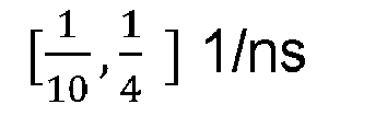
- Different decay factor for the Rician multi-path channel, e.g., A ∈ [0.05,0.50 ] dB/ns
- Different ray arrival for the Rician multi-path channel, e.g., λ ∈
- CFO between devices [-5, 5] ppm
- For each simulated radio channel, 80 complex-valued vector of IQ samples may be constructed 80 tones in the ISM band, with a frequency step of 1 MHz, corresponding to 160 rea-valued number input to the input layer of the above neural network.
- A neural network 3000 as described above was trained as described above. Performance was verified based on simulations and physical measurements. In particular, it was seen that that combining the velocity compensation with a neural network as per the present inventive concept leads to a decrease in the error in the determined distance as compared to employing the doppler compensation alone combined with conventional distance determination methods, such as a super-resolution algorithm, such as the MUSIC algorithm, while providing more robustness.
- In the above the inventive concept has mainly been described with reference to a limited number of examples. However, as is readily appreciated by a person skilled in the art, other examples than the ones disclosed above are equally possible within the scope of the inventive concept, as defined by the appended claims.
Claims (13)
1. A method (1000) of phase-based ranging between a first device (110) and a second device (120), comprising:
receiving (1010) a plurality two-way phase-measurements between the first device (110) and the second device (120) performed at a plurality of frequencies;
identifying (1020) a first measurement and a second measurement of said plurality of two-way phase measurements having been performed at a same frequency;
calculating (1030) a relative speed between said first device (110) and said second device (120) based at least on said first measurement and said second measurement;
doppler compensating (1040) a plurality of measurements of said plurality of two-way phase measurements based on the calculated relative speed; and
calculating (1050) a distance between said first device (110) and said second device (120) based on the doppler compensated measurements, wherein said calculating comprises inputting the doppler compensated measurements to a neural network (300).
2. The method (1000) of claim 1, wherein each two-way phase measurement of said plurality of two-way phase measurements is a pair of in-phase, I, and quadrature, Q, measurements, a phase-magnitude-pair, or any other pair of numbers representable as a complex number.
3. The method (1000) of any one of the preceding claims wherein the frequencies of said plurality of two-way phase measurements are pseudo-randomly ordered in time.
4. The method (1000) of any one of claims 1-3, further comprising, before said inputting of the doppler compensated measurements to said neural network, reordering at least a subset of the measurements in a pre-determined order.
5. The method (1000) of any one of claims 1-3, further comprising, before said inputting of the doppler compensated measurements to said neural network, reordering at least a subset of the measurements to a linear frequency ramp.
6. The method (1000) of any one of claims 1-3, further comprising, before said inputting of the doppler compensated measurements to said neural network, reordering and distributing at least a subset of the measurements to at least a first linear frequency ramp and a second linear frequency ramp, and wherein said neural network is a first neural network and said inputting of the doppler compensated measurements to said neural network comprises inputting the measurements of the first linear frequency ramp to said first neural network and inputting the measurements of the second linear frequency ramp to a second neural network.
7. The method (1000) of any one of claims 3-6, wherein the pseudo-random order in time of the frequencies of said plurality of two-way phase measurements is according to US FCC regulation 47 CFR §15.247.
8. The method (1000) of any one of claims 1-7, wherein said relative speed is calculated based on a phase difference between said second measurement and said first measurement, said same frequency, and a time difference between said second measurement and said first measurement
9. The method (1000) of any one of claims 1-8, wherein said relative speed is calculable as: 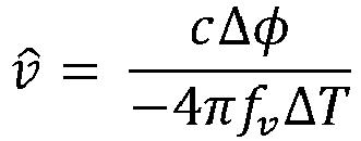
wherein v̂ is the estimated relative speed, c is the speed of light, fv is said same frequency, ΔT is a time difference between said second measurement and said first measurement, and Δϕ is a phase difference between said second measurement and said first measurement.
10. The method (1000) of any one of claims 1-9, wherein a doppler compensation of said doppler compensating is calculated based on the frequency of the measurement, the estimated relative speed, the time of measurement at the first device and the time of measurement at the second device.
11. The method (1000) of any one of claims 1-9, wherein a doppler compensation of said doppler compensating is calculable as: 
wherein f is the frequency of the measurement, v̂ is the estimated relative speed, c is the speed of light, tA is a time of measurement at the first device and tB is a time of measurement at the second device.
11. A device configured to perform the method of any one of claims 1-11.
12. A non-transitory computer-readable medium comprising instructions which, when executed by a computer or processor, causes the computer or processor to carry out the method of any one of claims 1-11.
Priority Applications (2)
| Application Number | Priority Date | Filing Date | Title |
|---|---|---|---|
| EP23220569.0A EP4579281A1 (en) | 2023-12-28 | 2023-12-28 | Phased-based ranging |
| US18/999,558 US20250216544A1 (en) | 2023-12-28 | 2024-12-23 | Phased-based ranging |
Applications Claiming Priority (1)
| Application Number | Priority Date | Filing Date | Title |
|---|---|---|---|
| EP23220569.0A EP4579281A1 (en) | 2023-12-28 | 2023-12-28 | Phased-based ranging |
Publications (1)
| Publication Number | Publication Date |
|---|---|
| EP4579281A1 true EP4579281A1 (en) | 2025-07-02 |
Family
ID=89427002
Family Applications (1)
| Application Number | Title | Priority Date | Filing Date |
|---|---|---|---|
| EP23220569.0A Pending EP4579281A1 (en) | 2023-12-28 | 2023-12-28 | Phased-based ranging |
Country Status (2)
| Country | Link |
|---|---|
| US (1) | US20250216544A1 (en) |
| EP (1) | EP4579281A1 (en) |
Citations (1)
| Publication number | Priority date | Publication date | Assignee | Title |
|---|---|---|---|---|
| US11184048B2 (en) | 2019-06-12 | 2021-11-23 | Stichting Imec Nederland | System and method for distance and velocity estimation in phase-based ranging |
-
2023
- 2023-12-28 EP EP23220569.0A patent/EP4579281A1/en active Pending
-
2024
- 2024-12-23 US US18/999,558 patent/US20250216544A1/en active Pending
Patent Citations (1)
| Publication number | Priority date | Publication date | Assignee | Title |
|---|---|---|---|---|
| US11184048B2 (en) | 2019-06-12 | 2021-11-23 | Stichting Imec Nederland | System and method for distance and velocity estimation in phase-based ranging |
Non-Patent Citations (2)
| Title |
|---|
| ALIREZA SHEIKH: "Phase-Based Ranging in Narrowband Systems With Missing/Interfered Tones", IEEE INTERNET OF THINGS JOURNAL, vol. 10, no. 17, 1 September 2023 (2023-09-01), pages 15171 - 15185, XP093158700, ISSN: 2372-2541, DOI: 10.1109/JIOT.2023.3264790 * |
| ZAUGG E C ET AL: "Theory and Application of Motion Compensation for LFM-CW SAR", IEEE TRANSACTIONS ON GEOSCIENCE AND REMOTE SENSING, IEEE, USA, vol. 46, no. 10, 1 October 2008 (2008-10-01), pages 2990 - 2998, XP011235710, ISSN: 0196-2892, DOI: 10.1109/TGRS.2008.921958 * |
Also Published As
| Publication number | Publication date |
|---|---|
| US20250216544A1 (en) | 2025-07-03 |
Similar Documents
| Publication | Publication Date | Title |
|---|---|---|
| EP3751303B1 (en) | System and method for distance and velocity estimation in phase-based ranging | |
| Sit et al. | The OFDM joint radar-communication system: An overview | |
| US11555881B2 (en) | Locating method for localizing at least one object using wave-based signals and locating system | |
| JP6123974B2 (en) | Radar equipment | |
| CN107076834B (en) | Radar operation with increased Doppler capability | |
| He et al. | Generalized Cramér–Rao bound for joint estimation of target position and velocity for active and passive radar networks | |
| CN101128988B (en) | Method and apparatus for channel estimation to electro-magnetic wave multi path between sender and receiver by using chirp signal | |
| Pelka et al. | Accurate radio distance estimation by phase measurements with multiple frequencies | |
| CN106950532B (en) | A Time Delay Estimation Method Based on the Comparison of Mutual Fuzzy Function and Waveform Similarity | |
| JP2019113529A (en) | Method for determining distance | |
| KR20020026464A (en) | Time of arrival estimation for positioning systems | |
| US11846695B2 (en) | Radio frequency distance determination | |
| US20240085547A1 (en) | A hybrid method for time-of-arrival-based ranging | |
| EP3839562B1 (en) | Method for distance determination | |
| US20250216544A1 (en) | Phased-based ranging | |
| Naderi et al. | The design of measurement-based underwater acoustic channel simulators using the INLSA algorithm | |
| EP4465088A1 (en) | Phased-based ranging | |
| JPH11234190A (en) | Maximum doppler frequency observation circuit, radio channel estimation circuit and object moving speed observation circuit | |
| Pham et al. | On the double Doppler effect generated by scatterer motion | |
| Rezzouki et al. | Net fishing localization: Performance of tdoa-based positioning technique in underwater acoustic channels using chirp signals | |
| CN118519092A (en) | Method and apparatus for determining duration of signal propagation | |
| WO2023032901A1 (en) | Positioning system and positioning method | |
| US11815591B2 (en) | Distance estimation method in an LPWA network and a position estimation method associated therewith | |
| KR100916640B1 (en) | Wireless communication based distance estimation method between transmitting and receiving devices | |
| RU2568897C1 (en) | Method of measurement of mutual delay of signals |
Legal Events
| Date | Code | Title | Description |
|---|---|---|---|
| PUAI | Public reference made under article 153(3) epc to a published international application that has entered the european phase |
Free format text: ORIGINAL CODE: 0009012 |
|
| STAA | Information on the status of an ep patent application or granted ep patent |
Free format text: STATUS: THE APPLICATION HAS BEEN PUBLISHED |
|
| AK | Designated contracting states |
Kind code of ref document: A1 Designated state(s): AL AT BE BG CH CY CZ DE DK EE ES FI FR GB GR HR HU IE IS IT LI LT LU LV MC ME MK MT NL NO PL PT RO RS SE SI SK SM TR |
|
| STAA | Information on the status of an ep patent application or granted ep patent |
Free format text: STATUS: REQUEST FOR EXAMINATION WAS MADE |
|
| 17P | Request for examination filed |
Effective date: 20260102 |