EP4579278A1 - Ultrasound imaging system, method of controlling the ultrasound imaging system, and probe included in the ultrasound imaging system - Google Patents
Ultrasound imaging system, method of controlling the ultrasound imaging system, and probe included in the ultrasound imaging system Download PDFInfo
- Publication number
- EP4579278A1 EP4579278A1 EP24167136.1A EP24167136A EP4579278A1 EP 4579278 A1 EP4579278 A1 EP 4579278A1 EP 24167136 A EP24167136 A EP 24167136A EP 4579278 A1 EP4579278 A1 EP 4579278A1
- Authority
- EP
- European Patent Office
- Prior art keywords
- transducer array
- ultrasound
- ultrasound imaging
- imaging system
- ultrasound image
- Prior art date
- Legal status (The legal status is an assumption and is not a legal conclusion. Google has not performed a legal analysis and makes no representation as to the accuracy of the status listed.)
- Granted
Links
Images










Classifications
-
- G—PHYSICS
- G01—MEASURING; TESTING
- G01S—RADIO DIRECTION-FINDING; RADIO NAVIGATION; DETERMINING DISTANCE OR VELOCITY BY USE OF RADIO WAVES; LOCATING OR PRESENCE-DETECTING BY USE OF THE REFLECTION OR RERADIATION OF RADIO WAVES; ANALOGOUS ARRANGEMENTS USING OTHER WAVES
- G01S7/00—Details of systems according to groups G01S13/00, G01S15/00, G01S17/00
- G01S7/52—Details of systems according to groups G01S13/00, G01S15/00, G01S17/00 of systems according to group G01S15/00
- G01S7/52017—Details of systems according to groups G01S13/00, G01S15/00, G01S17/00 of systems according to group G01S15/00 particularly adapted to short-range imaging
- G01S7/52079—Constructional features
- G01S7/52084—Constructional features related to particular user interfaces
-
- A—HUMAN NECESSITIES
- A61—MEDICAL OR VETERINARY SCIENCE; HYGIENE
- A61B—DIAGNOSIS; SURGERY; IDENTIFICATION
- A61B8/00—Diagnosis using ultrasonic, sonic or infrasonic waves
- A61B8/54—Control of the diagnostic device
-
- A—HUMAN NECESSITIES
- A61—MEDICAL OR VETERINARY SCIENCE; HYGIENE
- A61B—DIAGNOSIS; SURGERY; IDENTIFICATION
- A61B8/00—Diagnosis using ultrasonic, sonic or infrasonic waves
- A61B8/44—Constructional features of the ultrasonic, sonic or infrasonic diagnostic device
- A61B8/4477—Constructional features of the ultrasonic, sonic or infrasonic diagnostic device using several separate ultrasound transducers or probes
-
- A—HUMAN NECESSITIES
- A61—MEDICAL OR VETERINARY SCIENCE; HYGIENE
- A61B—DIAGNOSIS; SURGERY; IDENTIFICATION
- A61B8/00—Diagnosis using ultrasonic, sonic or infrasonic waves
- A61B8/44—Constructional features of the ultrasonic, sonic or infrasonic diagnostic device
- A61B8/4483—Constructional features of the ultrasonic, sonic or infrasonic diagnostic device characterised by features of the ultrasound transducer
- A61B8/4488—Constructional features of the ultrasonic, sonic or infrasonic diagnostic device characterised by features of the ultrasound transducer the transducer being a phased array
-
- A—HUMAN NECESSITIES
- A61—MEDICAL OR VETERINARY SCIENCE; HYGIENE
- A61B—DIAGNOSIS; SURGERY; IDENTIFICATION
- A61B8/00—Diagnosis using ultrasonic, sonic or infrasonic waves
- A61B8/46—Ultrasonic, sonic or infrasonic diagnostic devices with special arrangements for interfacing with the operator or the patient
- A61B8/461—Displaying means of special interest
- A61B8/463—Displaying means of special interest characterised by displaying multiple images or images and diagnostic data on one display
-
- A—HUMAN NECESSITIES
- A61—MEDICAL OR VETERINARY SCIENCE; HYGIENE
- A61B—DIAGNOSIS; SURGERY; IDENTIFICATION
- A61B8/00—Diagnosis using ultrasonic, sonic or infrasonic waves
- A61B8/46—Ultrasonic, sonic or infrasonic diagnostic devices with special arrangements for interfacing with the operator or the patient
- A61B8/461—Displaying means of special interest
- A61B8/465—Displaying means of special interest adapted to display user selection data, e.g. icons or menus
-
- A—HUMAN NECESSITIES
- A61—MEDICAL OR VETERINARY SCIENCE; HYGIENE
- A61B—DIAGNOSIS; SURGERY; IDENTIFICATION
- A61B8/00—Diagnosis using ultrasonic, sonic or infrasonic waves
- A61B8/46—Ultrasonic, sonic or infrasonic diagnostic devices with special arrangements for interfacing with the operator or the patient
- A61B8/467—Ultrasonic, sonic or infrasonic diagnostic devices with special arrangements for interfacing with the operator or the patient characterised by special input means
-
- A—HUMAN NECESSITIES
- A61—MEDICAL OR VETERINARY SCIENCE; HYGIENE
- A61B—DIAGNOSIS; SURGERY; IDENTIFICATION
- A61B8/00—Diagnosis using ultrasonic, sonic or infrasonic waves
- A61B8/46—Ultrasonic, sonic or infrasonic diagnostic devices with special arrangements for interfacing with the operator or the patient
- A61B8/467—Ultrasonic, sonic or infrasonic diagnostic devices with special arrangements for interfacing with the operator or the patient characterised by special input means
- A61B8/469—Ultrasonic, sonic or infrasonic diagnostic devices with special arrangements for interfacing with the operator or the patient characterised by special input means for selection of a region of interest
-
- A—HUMAN NECESSITIES
- A61—MEDICAL OR VETERINARY SCIENCE; HYGIENE
- A61B—DIAGNOSIS; SURGERY; IDENTIFICATION
- A61B8/00—Diagnosis using ultrasonic, sonic or infrasonic waves
- A61B8/52—Devices using data or image processing specially adapted for diagnosis using ultrasonic, sonic or infrasonic waves
- A61B8/5207—Devices using data or image processing specially adapted for diagnosis using ultrasonic, sonic or infrasonic waves involving processing of raw data to produce diagnostic data, e.g. for generating an image
-
- G—PHYSICS
- G01—MEASURING; TESTING
- G01S—RADIO DIRECTION-FINDING; RADIO NAVIGATION; DETERMINING DISTANCE OR VELOCITY BY USE OF RADIO WAVES; LOCATING OR PRESENCE-DETECTING BY USE OF THE REFLECTION OR RERADIATION OF RADIO WAVES; ANALOGOUS ARRANGEMENTS USING OTHER WAVES
- G01S15/00—Systems using the reflection or reradiation of acoustic waves, e.g. sonar systems
- G01S15/88—Sonar systems specially adapted for specific applications
- G01S15/89—Sonar systems specially adapted for specific applications for mapping or imaging
- G01S15/8906—Short-range imaging systems; Acoustic microscope systems using pulse-echo techniques
- G01S15/8909—Short-range imaging systems; Acoustic microscope systems using pulse-echo techniques using a static transducer configuration
- G01S15/8915—Short-range imaging systems; Acoustic microscope systems using pulse-echo techniques using a static transducer configuration using a transducer array
- G01S15/8925—Short-range imaging systems; Acoustic microscope systems using pulse-echo techniques using a static transducer configuration using a transducer array the array being a two-dimensional transducer configuration, i.e. matrix or orthogonal linear arrays
-
- G—PHYSICS
- G01—MEASURING; TESTING
- G01S—RADIO DIRECTION-FINDING; RADIO NAVIGATION; DETERMINING DISTANCE OR VELOCITY BY USE OF RADIO WAVES; LOCATING OR PRESENCE-DETECTING BY USE OF THE REFLECTION OR RERADIATION OF RADIO WAVES; ANALOGOUS ARRANGEMENTS USING OTHER WAVES
- G01S15/00—Systems using the reflection or reradiation of acoustic waves, e.g. sonar systems
- G01S15/88—Sonar systems specially adapted for specific applications
- G01S15/89—Sonar systems specially adapted for specific applications for mapping or imaging
- G01S15/8906—Short-range imaging systems; Acoustic microscope systems using pulse-echo techniques
- G01S15/8909—Short-range imaging systems; Acoustic microscope systems using pulse-echo techniques using a static transducer configuration
- G01S15/8915—Short-range imaging systems; Acoustic microscope systems using pulse-echo techniques using a static transducer configuration using a transducer array
- G01S15/8927—Short-range imaging systems; Acoustic microscope systems using pulse-echo techniques using a static transducer configuration using a transducer array using simultaneously or sequentially two or more subarrays or subapertures
-
- G—PHYSICS
- G01—MEASURING; TESTING
- G01S—RADIO DIRECTION-FINDING; RADIO NAVIGATION; DETERMINING DISTANCE OR VELOCITY BY USE OF RADIO WAVES; LOCATING OR PRESENCE-DETECTING BY USE OF THE REFLECTION OR RERADIATION OF RADIO WAVES; ANALOGOUS ARRANGEMENTS USING OTHER WAVES
- G01S7/00—Details of systems according to groups G01S13/00, G01S15/00, G01S17/00
- G01S7/52—Details of systems according to groups G01S13/00, G01S15/00, G01S17/00 of systems according to group G01S15/00
- G01S7/52017—Details of systems according to groups G01S13/00, G01S15/00, G01S17/00 of systems according to group G01S15/00 particularly adapted to short-range imaging
- G01S7/52085—Details related to the ultrasound signal acquisition, e.g. scan sequences
- G01S7/5209—Details related to the ultrasound signal acquisition, e.g. scan sequences using multibeam transmission
Definitions
- the disclosure relates to an ultrasound imaging system, a method of controlling the ultrasound imaging system, and a probe included in the ultrasound imaging system.
- medical imaging apparatuses for imaging information about biological tissue of the human body, for the purpose of early diagnosis of various diseases or surgical operations, are being widely used.
- Representative examples of such medical imaging apparatuses may include an ultrasound imaging apparatus, a computed tomography (CT) apparatus, and a magnetic resonance imaging (MRI) apparatus.
- CT computed tomography
- MRI magnetic resonance imaging
- a method of controlling an ultrasound imaging system includes receiving a user input related to a setting value of an ultrasound image, identifying the setting value of the ultrasound image included in the user input, setting an activation transducer array used to generate the ultrasound image among a first transducer array and a second transducer array having different specifications, based on the setting value, receiving ultrasound data through the activation transducer array, and displaying the ultrasound image by using the ultrasound data.
- the probe 20 may include a wired probe that is connected to the ultrasound imaging apparatus 40 by wire to communicate with the ultrasound imaging apparatus 40 by wire, a wireless probe that is wirelessly connected to the ultrasound imaging apparatus 40 to communicate wirelessly with the ultrasound imaging apparatus 40, and/or a hybrid probe that is connected to the ultrasound imaging apparatus 40 by wire or wirelessly to communicate with the ultrasound imaging apparatus 40 by wire or wirelessly.
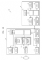
- the ultrasound imaging apparatus 40 may include an ultrasound transmission/reception module 110 as shown in FIG. 1A , or the probe 20 may include the ultrasonic transmission/reception module 110 as shown in FIG. 1B . According to various embodiments, the ultrasound imaging apparatus 40 and the probe 20 may include the ultrasound transmission/reception module 110.
- the probe 20 may include a plurality of transducers.
- the plurality of transducers may be arranged in a predetermined configuration to be implemented as a transducer array.
- the transducer array may correspond to a one-dimensional (1D) array or a two-dimensional (2D) array.
- the plurality of transducers may transmit an ultrasound signal to an object 10 according to a transmission signal applied by a transmission module 113 included in the ultrasound transmission/reception module 110.
- the plurality of transducers may receive an ultrasound signal (echo signal) reflected by the object 10 to form a reception signal.
- the probe 20 may be integrated with the ultrasound imaging apparatus 40, or may be separate from the ultrasound imaging apparatus 40 and may be connected thereto via a wired communication.
- the ultrasound imaging apparatus 40 may be connected to one probe 20 or a plurality of probes 20 according to embodiments.
- the 2D transducer array may include a plurality of sub-arrays arranged in a second direction different from a first direction and each including a plurality of transducers arranged in the first direction.
- the processor 120 may calculate a time delay value for digital beamforming for each sub-array with respect to each of the plurality of sub-arrays included in the 2D transducer array.
- the processor 120 may calculate a time delay value for analog beamforming with respect to each of the plurality of transducer included in one of the plurality of sub-arrays.
- the processor 120 may control the analog beamformer and the digital beamformer to form a transmission signal that is to be applied to each of the plurality of transducers, according to the time delay value for analog beamforming and the time delay value for digital beamforming.
- the processor 120 may control the analog beamformer to sum signals received from the plurality of transducers for each sub-array according to the time delay value for analog beamforming.
- the processor 120 may control the ultrasound transmission/reception module 110 to perform analog-to-digital conversion with respect to a result of the summation of the signals for each sub-array.
- the processor 120 may control the digital beamformer to generate ultrasound data, by summing digital signals according to the time delay value for digital beamforming.
- the display 140 may display the generated ultrasound image, and various pieces of information processed by the ultrasound imaging apparatus 40 or the probe 20.
- the probe 20 or the ultrasound imaging apparatus 40 may include one display 140 or a plurality of displays 140 according to implementation types.
- the display 140 may include a touch panel or touch screen.
- the display 140 may include a flexible display.
- the processor 120 may control an overall operation of the ultrasound imaging apparatus 40 and may control operations of the components of the ultrasound imaging apparatus 40.
- the processor 120 may perform or control various operations or functions of the ultrasound imaging apparatus 40 by executing programs or instructions stored in the memory 150.
- the processor 120 may receive a control signal from the input interface 170 or an external device to control an operation of the ultrasound imaging apparatus 40.
- the ultrasound imaging apparatus 40 may include a communication module 160, and may be connected to and communicate with external devices (e.g., the probe 20, a server, a medical apparatus, and a portable device (smartphone, tablet personal computer (PC), wearable device, etc.), via the communication module 160.
- external devices e.g., the probe 20, a server, a medical apparatus, and a portable device (smartphone, tablet personal computer (PC), wearable device, etc.
- the communication module 160 may include at least one component that enables communication with the external devices.
- the communication module 160 may include, for example, at least one of a close-distance communication module, a wired communication module, or a wireless communication module.
- a program or application related to the ultrasound imaging apparatus 40 may be installed in the external device.
- the program or application installed in the external device may control the ultrasonic imaging apparatus 40, or may operate according to the control signal or data received from the ultrasonic imaging apparatus 40.
- the external device may receive or download the program or application related to the ultrasound imaging apparatus 40 from the ultrasound imaging apparatus 40, the probe 20, or a server, and may provide and execute the program or application in the external device.
- the ultrasound imaging apparatus 40, the probe 20, or the server providing the program or application may include a recording medium that stores instructions, commands, installation files, executable files, or related data of the program or application.
- the external device may also be sold with programs or applications provided.
- FIG. 1B is a block diagram showing control by the ultrasound imaging system 100 when the probe 20 is a wired probe or a hybrid probe.
- the ultrasound imaging apparatus 40 shown in FIG. 1B may be replaced by the ultrasound imaging apparatus 40 described above with reference to FIG. 1A .
- the probe 20 shown in FIG. 1A may be replaced by the probe 20 described above with reference to FIG. 1B .
- the probe 20 may include a display 112, a transmission module 113, a battery 114, a transducer 115, a charging module 116, a reception module 117, an input interface 109, a processor 118, and a communication module 119.
- the probe 20 is shown as including both the transmission module 113 and the reception module 117.
- the probe 20 may include only some of the transmission module 113 and the reception module 117, or some of the transmission module 113 and the reception module 117 may be included in the ultrasound imaging apparatus 40.
- the probe 20 may further include an image processor 130.
- the transducer 115 may include a plurality of transducers.
- the plurality of transducers may be arranged in a predetermined configuration to be implemented as a transducer array.
- the transducer array may correspond to a one-dimensional (1D) array or a two-dimensional (2D) array.
- the plurality of transducers may transmit an ultrasound signal to the object 10 according to a transmission signal applied by the transmission module 113.
- the plurality of transducers may receive an ultrasound signal reflected by the object 10 and may form or generate an electrical reception signal.
- the charging module 116 may charge the battery 114.
- the charging module 116 may receive power from an external source. According to an embodiment, the charging module 116 may receive power wirelessly. According to an embodiment, the charging module 116 may receive power by wire. The charging module 116 may transmit the received power to the battery 114.
- the processor 118 controls the transmission module 113 to generate or form a transmission signal that is to be applied to each of the plurality of transducers 115, considering respective positions and focal points of the plurality of transducers.
- the processor 118 may control the reception module 117 to generate ultrasonic data by performing analog-to-digital conversion on a reception signal received from the transducer 115 and summing a digital reception signal considering the respective positions and focus points of the plurality of transducers.
- the probe 20 may generate an ultrasound image by using the generated ultrasound data.
- the processor 118 may calculate a time delay value for digital beamforming for each sub-array with respect to each of the plurality of sub-arrays included in the 2D transducer array.
- the processor 118 may calculate a time delay value for analog beamforming with respect to each of the plurality of transducer included in one of the plurality of sub-arrays.
- the processor 118 may control the analog beamformer and the digital beamformer to form a transmission signal that is to be applied to each of the plurality of transducers, according to the time delay value for analog beamforming and the time delay value for digital beamforming.
- the processor 118 may control the analog beamformer to sum signals received from the plurality of transducers for each sub-array according to the time delay value for analog beamforming.
- the processor 118 may control the ultrasound transmission/reception module 110 to perform analog-to-digital conversion with respect to a result of the summation of the signals for each sub-array.
- the processor 118 may control the digital beamformer to generate ultrasound data, by summing digital signals according to the time delay value for digital beamforming.
- the processor 118 may control an overall operation of the probe 20 and may control operations of the components of the probe 20.
- the processor 118 may perform or control various operations or functions of the probe 20 by executing programs or instructions stored in the memory 111.
- the processor 118 may receive a control signal from the input interface 109 of the probe 20 or an external device (e.g., the ultrasound imaging apparatus 40) to control an operation of the probe 20.
- the processor 118 may receive a control signal from the input interface 109 or the external device to control an operation of the probe 20.
- the input interface 109 may receive a user input for controlling the probe 20.
- the user input may include, but is not limited to, an input for manipulating a button, a key pad, a mouse, a trackball, a jog switch, a knop, or the like, an input for touching a touch pad or a touch screen, a voice input, a motion input, and a biometric data input (e.g., iris recognition and fingerprint recognition).
- an input for manipulating a button e.g., a key pad, a mouse, a trackball, a jog switch, a knop, or the like
- an input for touching a touch pad or a touch screen e.g., a voice input, a motion input
- a biometric data input e.g., iris recognition and fingerprint recognition
- the display 112 displays an ultrasound image generated by the probe 20, an ultrasound image generated by processing ultrasound data generated by the probe 20, an ultrasound image received from the ultrasound imaging apparatus 40, or various pieces of information that are processed by the ultrasound imaging system 100.
- the display 112 may further display status information of the probe 20.
- the status information of the probe 20 may include device information of the probe 20, battery status information of the probe 20, frequency band information of the probe 20, output information of the probe 20, information regarding occurrence or non-occurrence of abnormality of the probe 20, setting information of the probe 20, or temperature information of the probe 20.
- the probe 20 may include one display 112 or a plurality of displays 112 according to implementation types.
- the display 112 may include a touch panel or touch screen.
- the display 112 may include a flexible display.
- the communication module 119 may wirelessly transmit the generated ultrasound data or ultrasound image to the ultrasound imaging apparatus 40 through a wireless network.
- the communication module 119 may receive a control signal or data from the ultrasound imaging apparatus 40.
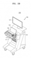
- FIGS. 2A , 2B , 2C , and 2D are views illustrating an ultrasound imaging apparatus 100 according to an embodiment.
- the ultrasound imaging system 100 may identify whether the magnification ratio is greater than or equal to a minimum change value.
- the minimum change value may be a magnification ratio that causes the transmission/reception frequency of the activation transducer array to change.
- the minimum change value may be x1.
- the ultrasound imaging system 100 may proceed to operation 1030 when the magnification ratio is greater than or equal to the minimum change value (operation 1020 - YES).
- the ultrasound imaging system 100 may terminate the process of setting an activation transducer array.
- the ultrasound imaging system 100 may change the activation transducer array.
- the activation transducer array may be a transducer array used by the ultrasound imaging system 100 to obtain an ultrasound image.
- the ultrasound imaging system 100 may automatically change the activation transducer array. For example, when the magnification ratio is x10, the ultrasound imaging system 100 may change the activation transducer array from the convex transducer array to the linear transducer array.
- the ultrasound imaging system 100 may change the transmission/reception frequency of the activation transducer array.
- the ultrasound imaging system 100 may change the transmission/reception frequency of the activation transducer array while maintaining the activation transducer array.
- the magnification ratio is x4
- the ultrasound imaging system 100 may change the transmission/reception frequency of the activation transducer array to 4MHz while maintaining the convex transducer array as the activation transducer array.
- the ultrasound imaging system 100 may display a guidance window notifying that a function of setting an activation transducer array has been executed.
- the ultrasound imaging system 100 may provide information that a function of automatically selecting an activation transducer array is being executed, through the guidance window.
- the ultrasound imaging system 100 may display a guiding phrase "Optimizing" through the guidance window.
- the ultrasound imaging system 100 may identify whether a function termination input has been received.
- the ultrasound imaging system 100 may identify whether a function termination input has been received, through the information window. For example, the ultrasound imaging system 100 may identify whether an input of clicking the information window has been received.
- the ultrasound imaging system 100 may proceed to operation 1080 when the function termination input has been received (operation 1070 - YES).
- operation 1070 - NO When the function termination input has not been received (operation 1070 - NO), the ultrasound imaging system 100 may maintain a state of continuously executing the function of setting the activation transducer array.
- the ultrasound imaging system 100 may terminate the function of setting the activation transducer array.
- the ultrasound imaging system 100 may terminate the function of setting the activation transducer array, in response to the function termination input.
- the ultrasound imaging system 100 may terminate display of the guidance window notifying that the function of setting an activation transducer array has been executed.
- the ultrasound imaging system 100 may set the depth of the ultrasound image to be 5mm.
- the setting of the depth of the ultrasound image to be 5mm may be referred to as setting a basic depth.
- the ultrasound imaging system 100 may display the ultrasound image representing an object by the basic depth.
- the ultrasound imaging system 100 may select a linear transducer array to display the ultrasound image representing an object by the basic depth.
- the linear transducer array may correspond to the second transducer array 320 described above with reference to FIG. 3 .
- the linear transducer array may transmit and receive an ultrasonic signal belonging to a second frequency band 1102.
- the ultrasound imaging system 100 may set the transmission/reception frequency as a first frequency spectrum 1105 to display the ultrasound image representing an object by the basic depth.
- the ultrasound imaging system 100 may set the transmission/reception frequency as 12MHz belonging to the second frequency spectrum 1102 in order to display the ultrasound image representing an object by the basic depth.
- a transducer array using a first frequency band 1101 may be deactivated.
- the ultrasound imaging system 100 may set the depth of the ultrasound image to be 8mm.
- the ultrasound imaging system 100 may receive a user input for changing the ultrasound image to a first depth ultrasound image capable of representing the object with a depth greater than the basic depth.
- the ultrasound imaging system 100 may receive a user's depth increasing input of changing the ultrasound image to the first depth ultrasound image.
- the ultrasound imaging system 100 may receive a button input indicating the depth of 8 mm as a number.
- the ultrasound imaging system 100 may set a linear transducer array as the activation transducer array to display the first depth ultrasound image.
- the activation transducer array may be a transducer array used to display an ultrasound image.
- the activation transducer array may be a transducer array for transmitting a transmission signal to display an ultrasound image.
- the linear transducer array may transmit and receive an ultrasonic signal belonging to the second frequency band 1102.
- the ultrasound imaging system 100 may set the transmission/reception frequency as a second frequency spectrum 1125 to display the first depth ultrasound image.
- the ultrasound imaging system 100 may set the transmission/reception frequency as 6MHz to display the first depth ultrasound image. 6MHz may belong to the second frequency band 1102.
- the ultrasound imaging system 100 may change the spectrum of the transmission/reception frequency within the second frequency band 1102 from the first frequency spectrum 1105 to the second frequency spectrum 1125.
- a transducer array using the first frequency band 1101 may be deactivated.
- the ultrasound imaging system 100 may change the transmission/reception frequency of the activation transducer array.
- the minimum identification value may be a minimum value capable of identifying an ultrasound image generated using a signal.
- the minimum identification value may be -20dB.
- the ultrasound imaging system 100 may set the depth of the ultrasound image to be 12mm.
- the ultrasound imaging system 100 may receive a user input for changing the ultrasound image to a second depth ultrasound image capable of representing the object with a greater depth than the first depth ultrasound image.
- the ultrasound imaging system 100 may receive a user's depth increasing input of changing the first depth ultrasound image to the second depth ultrasound image.
- the ultrasound imaging system 100 may receive a button input indicating the depth of 12 mm as a number.
- the ultrasound imaging system 100 may change the activation transducer array from the linear transducer array to the convex transducer array to display the second depth ultrasound image.
- the convex transducer array may transmit and receive an ultrasonic signal belonging to the first frequency band 1101.
- the first frequency band 1101 may be lower than the second frequency band 1102.
- the ultrasound imaging system 100 may set the transmission/reception frequency as a third frequency spectrum 1135 to display the second depth ultrasound image.
- the ultrasound imaging system 100 may set the transmission/reception frequency as 4MHz to display the second depth ultrasound image. 4MHz may belong to the first frequency band 1101.
- the ultrasound imaging system 100 may automatically change the transmission/reception frequency to 4 MHz belonging to the first frequency band 1101.
- the ultrasound imaging system 100 may automatically change the activation transducer array from the linear transducer array to the convex transducer array.
- a linear transducer array using the second frequency band 1102 may be deactivated.
- the ultrasound imaging system 100 may change the current activation transducer array. For example, when the ultrasound imaging system 100 is unable to change the transmission/reception frequency of a linear activation transducer array that is a current activation transducer array, the ultrasound imaging system 100 may automatically change the current activation transducer array from the linear transducer array to the convex transducer array. Accordingly, the ultrasound imaging system 100 according to the disclosure may improve the performance of displaying an ultrasound image having a changed depth, by automatically changing the activation transducer array in response to a user input of changing the depth of an ultrasound image.
- FIG. 12 is a second Ul 1200 displayed when the ultrasound imaging system 100 according to an embodiment changes the depth of an ultrasound image.
- the ultrasound imaging system 100 may display the second UI 1200 via the display 140 of the ultrasound imaging apparatus 40.
- the second UI 1200 may include an information display area 1210, an image display area 1220, and a guidance window 1230.
- the image display area 1220 may display an ultrasound image.
- the image display area 1220 may display an ultrasound image obtained using the activation transducer displayed on the information display area 1210.
- the image display area 1220 may display an ultrasound image obtained under the driving conditions displayed on the information display area 1210.
- the image display area 1220 may display an ultrasound image having a depth of 12mm.
- the guidance window 1230 may be a window notifying that a function of setting the activation transducer array has been executed.
- the guidance window 1230 may be formed to overlap the image display area 1220.
- the guidance window 1230 may be formed in a left lower portion of the image display area 1220.
- the guidance window 1230 may provide information indicating that the activation transducer array is automatically selected based on the setting value of the ultrasound image.
- the guidance window 1230 may display a guiding phrase "Optimizing.” Thus, a user may know that the ultrasound imaging system 100 is automatically selecting the activation transducer array, based on the setting value of the ultrasound image.
- the ultrasound imaging system 100 may terminate a function of setting the activation transducer array, in response to a function termination input received through a guidance window. For example, the ultrasound imaging system 100 may terminate a function of setting the activation transducer array, in response to an input of clicking a guidance window. Accordingly, when the user does not wish for the ultrasound imaging system 100 to automatically select the activation transducer array, the user may conveniently terminate the function of setting the activation transducer array.
- the ultrasound imaging system 100 may identify whether it is possible to decrease the transmission/reception frequency of the activation transducer array.
- the activation transducer array may have a designated frequency band.
- a convex transducer array may have a first frequency band and a linear transducer array may have a second frequency band.
- the ultrasound imaging system 100 may proceed to operation 1340 when it is possible to decrease the transmission/reception frequency of the activation transducer array (operation 1330 - YES).
- the ultrasound imaging system 100 may proceed to operation 1350 when it is not possible to decrease the transmission/reception frequency of the activation transducer array (operation 1330 - NO).
- the ultrasound imaging system 100 may change the transmission/reception frequency of the activation transducer array.
- the ultrasound imaging system 100 may change the transmission/reception frequency of the activation transducer array while maintaining the activation transducer array.
- the ultrasound imaging system 100 may change the transmission/reception frequency of the activation transducer array to 6MHz while maintaining the linear transducer array as the activation transducer array.
- the ultrasound imaging system 100 may change the activation transducer array.
- the ultrasound imaging system 100 may automatically change the activation transducer array. For example, when the depth is 12mm, the ultrasound imaging system 100 may change the activation transducer array from the linear transducer array to the convex transducer array.
- the ultrasound imaging system 100 may display a guidance window notifying that a function of setting an activation transducer array has been executed.
- the ultrasound imaging system 100 may provide information that a function of automatically selecting an activation transducer array is being executed, through the guidance window.
- the ultrasound imaging system 100 may display a guiding phrase "Optimizing" through the guidance window.
- the ultrasound imaging system 100 may identify whether a function termination input has been received.
- the ultrasound imaging system 100 may identify whether a function termination input has been received, through the information window. For example, the ultrasound imaging system 100 may identify whether an input of clicking the information window has been received.
- the ultrasound imaging system 100 may proceed to operation 1380 when the function termination input has been received (operation 1370 - YES).
- operation 1370 - NO When the function termination input has not been received (operation 1370 - NO), the ultrasound imaging system 100 may maintain a state of continuously executing the function of setting the activation transducer array.
- the ultrasound imaging system 100 may terminate the function of setting the activation transducer array.
- the ultrasound imaging system 100 may terminate the function of setting the activation transducer array, in response to the function termination input.
- the ultrasound imaging system 100 may terminate display of the guidance window notifying that the function of setting an activation transducer array has been executed.
- FIG. 14 is a block diagram of the ultrasound imaging system 100 according to an embodiment.
- the ultrasound imaging system 100 may include a first beamformer 1410, a second beamformer 1420,... , and an N-th beamformer 1430 (where N is a natural number equal to or greater than 3).
- the ultrasound imaging system 100 may include a switching module 1440.
- the first beamformer 1410 may be connected to the first transducer array 310.
- the first beamformer 1410 may receive a setting signal from the ultrasound imaging apparatus 40.
- the first beamformer 1410 may transmit the setting signal to the first transducer array 310.
- the first beamformer 1410 may receive ultrasound data from the first transducer array 310.
- the first beamformer 1410 may transmit the ultrasound data to the ultrasound imaging apparatus 40.
- the second beamformer 1420 may be connected to the second transducer array 320.
- the second beamformer 1420 may receive the setting signal from the ultrasound imaging apparatus 40.
- the second beamformer 1420 may transmit the setting signal to the second transducer array 320.
- the second beamformer 1420 may receive the ultrasound data from the second transducer array 320.
- the second beamformer 1420 may transmit the ultrasound data to the ultrasound imaging apparatus 40.
- the N-th beamformer 1430 may be connected to an N-th transducer array 330.
- the N-th beamformer 1430 may receive the setting signal from the ultrasound imaging apparatus 40.
- the N-th beamformer 1430 may transmit the setting signal to the N-th transducer array 330.
- the N-th beamformer 1430 may receive the ultrasound data from the N-th transducer array 330.
- the N-th beamformer 1430 may transmit the ultrasound data to the ultrasound imaging apparatus 40.
- the switching module 1440 may receive the setting signal from the processor 120.
- the switching module 1440 may transmit the setting signal to an activation transducer array set by the processor 120 among the first transducer array 310, the second transducer array 320, and the N-th transducer array 330.
- the switching module 1440 may transmit the setting signal to at least one of the first beamformer 1410, the second beamformer 1420, and the N-th beamformer 1430. For example, when the processor 120 sets the first transducer array 310 as the activation transducer array, the switching module 1440 may transmit the setting signal to the first beamformer 1410.
- the switching module 1440 may transmit the setting signal to the first beamformer 1410 so that the first beamformer 1410 transmits the setting signal to the first transducer array 310.
- the switching module 1440 may transmit the setting signal to the first beamformer 1410 so that the first transducer array 310 obtains the ultrasound data.
- the switching module 1440 may receive the ultrasound data from the first beamformer 1410.
- FIG. 15 is a block diagram of the ultrasound imaging system 100 according to an embodiment.
- the ultrasound imaging system 100 may include a switching module 1510 and a beamformer 1520.
- the switching module 1510 may receive a setting signal from the beamformer 1520.
- the switching module 1510 may be connected to the first transducer array 310, the second transducer array 320, and the N-th transducer array 330.
- the switching module 1510 may transmit the setting signal to at least one of the first transducer array 310, the second transducer array 320, and the N-th transducer array 330.
- the switching module 1510 may receive the ultrasound data from at least one of the first transducer array 310, the second transducer array 320, and the N-th transducer array 330.
- the switching module 1510 may transmit the ultrasound data to the beamformer 1520.
- the beamformer 1520 may receive the setting signal from the processor 120. The beamformer 1520 may transmit the setting signal to the switching module 1510. The beamformer 1520 may receive the ultrasound data from the switching module 1510. The beamformer 1520 may transmit the ultrasound data to the processor 120.
- the disclosure provides an ultrasound imaging system having improving performance by displaying an ultrasound image by setting an activation transducer array that automatically obtains ultrasound data in accordance with a setting value of the ultrasound image, a method of controlling the ultrasound imaging system, and a probe included in the ultrasound imaging system.
- the disclosure seeks to improve a user convenience of manipulating ultrasound images by setting an activation transducer array based on image setting information worked by the user and automatically optimizing ultrasound image settings to display an ultrasound image.
- An ultrasound imaging system may include a first transducer array and a second transducer array having different specifications, a display configured to display an ultrasound image, based on ultrasound data received through at least one of the first transducer array and the second transducer array, an input interface configured to receive a user input related to a setting value of the ultrasound image, and a processor.
- the processor may identify the setting value of the ultrasound image included in the user input, set an activation transducer array used to generate the ultrasound image among the first transducer array and the second transducer array, based on the setting value, receive the ultrasound data through the activation transducer array, and control the display to display the ultrasound image by using the ultrasound data.
- the first transducer array and the second transducer array may have central axes parallel to each other and transmit transmission signals in same directions.
- the setting value may include at least one of the magnification ratio of the ultrasound image, the depth of the ultrasound image, and the location of a region of interest of the ultrasound image.
- the processor may change a transmission/reception frequency of the activation transducer array, and, when the magnification ratio is no less than the first threshold value, the processor may change the activation transducer array.
- the processor may change the activation transducer array, based on the setting value, and set a transmission parameter and a reception parameter such that the degree of change in the ultrasound image is maintained within a threshold range before and after the activation transducer array is changed.
- the transmission parameter may include at least one of a transmission waveform, a transmission frequency, and the number of transmissions
- the reception parameter may include at least one of a reception waveform, a reception frequency, a gain, and a dynamic range.
- the processor may set the transmission parameter and the reception parameter by using at least one of a correlation coefficient of the ultrasound image, a bias value of the ultrasound image, and artificial intelligence that analyzes the ultrasound image, before and after the activation transducer array is changed.
- the first transducer array may have a first structure among a plurality of structures.
- the second transducer array may have a second structure among the plurality of structures.
- the plurality of structures may include a lead zirconate titanate (PZT)-based piezoelectric structure, a single crystal-based piezoelectric structure, a polymer-based piezoelectric structure, a structure using a piezoelectric composite, a capacitive micromachined ultrasonic transducer (cMUT) structure using micro-electromagnetic system (MEMS) technology, and a piezoelectric micromachined ultrasonic transducer (pMUT) structure using MEMS technology.
- PZT lead zirconate titanate
- cMUT capacitive micromachined ultrasonic transducer
- MEMS micro-electromagnetic system
- pMUT piezoelectric micromachined ultrasonic transducer
- the ultrasound imaging system may further include a switching module configured to receive the ultrasound data by transmitting a setting signal to at least one of the first transducer array and the second transducer array, and a beamformer configured to transmit the setting signal from the processor to the switching module and transmit the ultrasound data from the switching module to the processor.
- a switching module configured to receive the ultrasound data by transmitting a setting signal to at least one of the first transducer array and the second transducer array
- a beamformer configured to transmit the setting signal from the processor to the switching module and transmit the ultrasound data from the switching module to the processor.
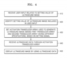
- a method of controlling an ultrasound imaging system may include receiving a user input related to a setting value of an ultrasound image, identifying the setting value of the ultrasound image included in the user input, setting an activation transducer array used to generate the ultrasound image among a first transducer array and a second transducer array having different specifications, based on the setting value, receiving ultrasound data through the activation transducer array, and displaying the ultrasound image by using the ultrasound data.
- the setting of the activation transducer array may include, when the magnification ratio is no less than a minimum change value and less than a first threshold value, changing a transmission/reception frequency of the activation transducer array, and, when the magnification ratio is no less than the first threshold value, changing the activation transducer array.
- the setting of the activation transducer array may include changing the activation transducer array, based on the setting value, and setting a transmission parameter and a reception parameter such that the degree of change in the ultrasound image is maintained within a threshold range before and after the activation transducer array is changed.
- the setting of the transmission parameter and a reception parameter may include setting the transmission parameter and the reception parameter by using at least one of a correlation coefficient of the ultrasound image, a bias value of the ultrasound image, and artificial intelligence that analyzes the ultrasound image, before and after the activation transducer array is changed.
- the setting of the activation transducer array may include displaying a guidance window indicating that a function of setting the activation transducer array has been executed, and terminating the function in response to a function termination input received through the guidance window.
- a probe may include a first transducer array, a second transducer array having a different specification from the first transducer array, and a processor.
- the processor may receive a setting signal from an ultrasound imaging apparatus that displays an ultrasound image, identify a setting value of the ultrasound image included in the setting signal, set an activation transducer array used to generate the ultrasound image among the first transducer array and the second transducer array, based on the setting value, receive ultrasound data through the activation transducer array, and transmit the ultrasound data to the ultrasound imaging apparatus.
- the first transducer array and the second transducer array may be arranged parallel to each other and transmit transmission signals in the same directions.
- An apparatus, method, or computer program perform an operation related to artificial intelligence (AI).
- An operation related to AI is executed through a processor and a memory.
- the processor may perform the operation related to AI by using one processor or a plurality of processors.
- the one or plurality of processors may be a general-purpose processor such as a central processing unit (CPU), an application processor (AP), or a digital signal processor (DSP), a graphics-only processor such as a graphics processing unit (GPU) or a vision processing unit (VPU), or an artificial intelligence (Al)-only processor such as a neural processing unit (NPU).
- the one or plurality of processors process input data, according to a program, instruction, or AI model stored in memory.
- the program, instruction, or AI model related to AI may be created through machine learning.
- being created through learning means that a basic AI model is trained using a plurality of training data by a learning algorithm, so that a program, instruction, or AI model performing desired characteristics (or a desired purpose) is created.
- Such learning may be performed in a device itself on which an AI operation according to an embodiment is performed, or may be performed through a separate server and/or system.
- Examples of the learning algorithm include, but are not limited to, supervised learning, unsupervised learning, semi-supervised learning, or reinforcement learning.
- the AI model may be composed of a plurality of neural network layers.
- Each of the plurality of neural network layers has a plurality of weight values, and performs a neural network operation through an operation between an operation result of a previous layer and the plurality of weight values.
- the plurality of weight values of the plurality of neural network layers may be optimized by a learning result of the Al model.
- An artificial neural network may include a deep neural network (DNN), for example, a Convolutional Neural Network (CNN), a Deep Neural Network (DNN), a Recurrent Neural Network (RNN), a Restricted Boltzmann Machine (RBM), a Deep Belief Network (DBN), a Bidirectional Recurrent Deep Neural Network (BRDNN), or a Deep Q-Networks, but embodiments of the disclosure are not limited thereto.
- DNN deep neural network
- CNN Convolutional Neural Network
- DNN Deep Neural Network
- RNN Recurrent Neural Network
- RBM Restricted Boltzmann Machine
- DBN Deep Belief Network
- BBN Bidirectional Recurrent Deep Neural Network
- Deep Q-Networks a Deep Q-Networks
- the machine-readable storage medium may be provided as a non-transitory storage medium.
- the 'non-transitory storage medium' is a tangible device and only means that it does not contain a signal (e.g., electromagnetic waves). This term does not distinguish a case in which data is stored semi-permanently in a storage medium from a case in which data is temporarily stored.
- the non-transitory recording medium may include a buffer in which data is temporarily stored.
Landscapes
- Health & Medical Sciences (AREA)
- Life Sciences & Earth Sciences (AREA)
- Engineering & Computer Science (AREA)
- Physics & Mathematics (AREA)
- Radar, Positioning & Navigation (AREA)
- Remote Sensing (AREA)
- Animal Behavior & Ethology (AREA)
- Medical Informatics (AREA)
- Veterinary Medicine (AREA)
- Biophysics (AREA)
- Nuclear Medicine, Radiotherapy & Molecular Imaging (AREA)
- Pathology (AREA)
- Radiology & Medical Imaging (AREA)
- Biomedical Technology (AREA)
- Heart & Thoracic Surgery (AREA)
- Public Health (AREA)
- Molecular Biology (AREA)
- Surgery (AREA)
- General Health & Medical Sciences (AREA)
- Acoustics & Sound (AREA)
- General Physics & Mathematics (AREA)
- Computer Networks & Wireless Communication (AREA)
- Gynecology & Obstetrics (AREA)
- Human Computer Interaction (AREA)
- Computer Vision & Pattern Recognition (AREA)
- Ultra Sonic Daignosis Equipment (AREA)
Abstract
Description
- This application is based on and claims priority to
Korean Patent Application No. 10-2023-0195382, filed on December 28, 2023 - The disclosure relates to an ultrasound imaging system, a method of controlling the ultrasound imaging system, and a probe included in the ultrasound imaging system.
- Recently, in the medical field, various medical imaging apparatuses for imaging information about biological tissue of the human body, for the purpose of early diagnosis of various diseases or surgical operations, are being widely used. Representative examples of such medical imaging apparatuses may include an ultrasound imaging apparatus, a computed tomography (CT) apparatus, and a magnetic resonance imaging (MRI) apparatus.
- Ultrasound imaging apparatuses transmit an ultrasound signal generated by a transducer of a probe to an object and receives information regarding a signal reflected by the object, thereby non-invasively obtaining at least one image of a part (e.g., a soft tissue or a blood stream) inside the object. Ultrasound imaging apparatuses may be used for medical purposes, such as observation of the inside of an object, detection of foreign substances inside the object, and diagnosis of damage thereof. Such ultrasound imaging apparatuses have various advantages, including stability, real-time display, and safety because there is no exposure to radiation, compared to X-ray imaging apparatuses, and thus, the ultrasound imaging apparatuses are commonly used together with other imaging apparatuses.
- A probe may include a plurality of transducers or a multi-purpose transducer (e.g., a 2D matrix transducer) in order to realize various purposes of an ultrasound imaging apparatus and ensure versatility. The probe may provide a linear array ultrasound image, a convex array ultrasound image, or a phased array ultrasound image to suit a user's purpose. The probe may first set a basic image and then receive a user input for improving image performance. For example, the probe may first set the type of transducer to be activated and then receive a zoom input. The zoom input received by the probe may not affect the type of set transducer. Accordingly, settings for a basic image may be maintained even when the probe receives a user input.
- Additional aspects will be set forth in part in the description which follows and, in part, will be apparent from the description, or may be learned by practice of the presented embodiments of the disclosure.
- An ultrasound imaging system according to an embodiment includes a first transducer array and a second transducer array having different specifications, a display configured to display an ultrasound image, based on ultrasound data received through at least one of the first transducer array and the second transducer array, an input interface configured to receive a user input related to a setting value of the ultrasound image, and a processor. The processor is configured to identify the setting value of the ultrasound image included in the user input, set an activation transducer array used to generate the ultrasound image among the first transducer array and the second transducer array, based on the setting value, receive the ultrasound data through the activation transducer array, and control the display to display the ultrasound image by using the ultrasound data.
- A method of controlling an ultrasound imaging system, according to an embodiment, includes receiving a user input related to a setting value of an ultrasound image, identifying the setting value of the ultrasound image included in the user input, setting an activation transducer array used to generate the ultrasound image among a first transducer array and a second transducer array having different specifications, based on the setting value, receiving ultrasound data through the activation transducer array, and displaying the ultrasound image by using the ultrasound data.
- This disclosure may be readily understood by reference to the following detailed description and the accompanying drawings, in which reference numerals refer to structural elements.
- The above and other aspects, features, and advantages of certain embodiments of the disclosure will be more apparent from the following description taken in conjunction with the accompanying drawings, in which:
-
FIGS. 1A and1B are block diagrams of an ultrasound imaging system according to an embodiment; -
FIGS. 2A ,2B ,2C , and2D are views illustrating an ultrasound imaging apparatus according to an embodiment; -
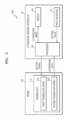
FIG. 3 is a block diagram of an ultrasound imaging system according to an embodiment; -
FIG. 4 is a flowchart of a method of controlling an ultrasound imaging system, according to an embodiment; -
FIG. 5 illustrates a first transducer array and a second transducer array according to an embodiment; -
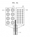
FIG. 6A illustrates first transducer units included in a first transducer array and second transducer units included in a second transducer array, according to an embodiment; -
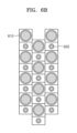
FIG. 6B illustrates a plurality of transducer units according to an embodiment; -
FIG. 7 is a flowchart illustrating an ultrasound imaging system, according to an embodiment, setting an activation transducer array and setting transmission parameters and reception parameters; -
FIG. 8 is a diagram illustrating an ultrasound imaging system, according to an embodiment, setting a frequency spectrum or an activation transducer array when changing the magnification ratio of an ultrasound image; -
FIG. 9 is a first user interface displayed when an ultrasound imaging system, according to an embodiment, changes the magnification ratio of an ultrasound image; -
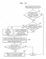
FIG. 10 is a flowchart of a process, performed by an ultrasound imaging system according to an embodiment, of setting a frequency spectrum or an activation transducer array when changing the magnification ratio of an ultrasound image; -
FIG. 11 is a diagram illustrating an ultrasound imaging system, according to an embodiment, setting a frequency spectrum or an activation transducer array when changing the depth of an ultrasound image; -
FIG. 12 is a second user interface displayed when an ultrasound imaging system, according to an embodiment, changes the depth of an ultrasound image; -
FIG. 13 is a flowchart of a process, performed by an ultrasound imaging system according to an embodiment, of setting a frequency spectrum or an activation transducer array when changing the depth of an ultrasound image; -
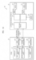
FIG. 14 is a block diagram of an ultrasound imaging system according to an embodiment; and -
FIG. 15 is a block diagram of an ultrasound imaging system according to an embodiment. - The principle of the disclosure is explained and embodiments are disclosed so that the scope of the disclosure is clarified and one of ordinary skill in the art to which embodiments pertain implements embodiments. Embodiments may have various forms.
- Throughout the specification, like reference numerals or characters refer to like elements. In the present specification, all elements of embodiments are not explained, but general matters in the technical field of the disclosure or redundant matters between embodiments will not be described. The term "module" or "unit" used herein may be implemented as one or more of software, hardware, or firmware. According to embodiments, a plurality of "modules" or "units" may be implemented as one element, or one "module" or "unit" may include a plurality of elements.
- The singular form of a noun corresponding to an item may include one item or a plurality of items, unless a relevant context clearly dictates otherwise.
- Each of expressions "A or B", "at least one of A and B", "at least one of A or B", and "one or more of A and/or B", "A, B, or C," "at least one of A, B, and C", and "at least one of A, B, or C" may include any one of listed items and all of at least one combination of the items.
- The term "and/or" used herein includes any and all combinations of one or more of the associated listed items.
- The terms such as "first", "second", "primarily", or "secondary" used herein may represent various elements regardless of order and/or importance, and do not limit corresponding elements. These terms may be used for distinguishing one element from another element.
- Terms such as 'front surface', 'rear surface', 'upper surface', 'lower surface', 'side surface', 'left side', 'right side', 'upper', and 'lower' used herein are defined based on the drawings, and the shape and location of each component are not limited by these terms.
- The terms such as "including," "having," and "comprising" used herein are intended to indicate the existence of the features, numbers, steps, actions, components, parts, or combinations thereof mentioned in the disclosure, and are not intended to preclude the possibility that one or more other features, numbers, steps, actions, components, parts, or combinations thereof may exist or may be added.
- When a component is said to be "connected to", "coupled to", "supported by" or "contact" another component, this may include not only a case where the components are directly connected to, coupled to, supported by, or contact each other, but also a case where the components are indirectly connected to, coupled to, supported by, or contact with each other through a third component.
- When a component is said to be located "on" another component, this includes not only a case in which a component is in contact with another component, but also a case in which another component exists between two components.
- Ultrasound apparatuses according to various embodiments will now be described in detail with reference to the attached drawings. In the drawings, like elements are denoted by like reference numerals, and a repeated explanation thereof will not be given.
- An image used herein may be a medical image captured by a medical imaging apparatus, such as a magnetic resonance imaging (MRI) apparatus, a computed tomography (CT) apparatus, an ultrasound imaging apparatus, or an X-ray imaging apparatus.
- Throughout the specification, a term 'object' is a thing to be imaged, and may include a human, an animal, or a part of a human or animal. For example, the object may include a part of a body (i.e., an organ), a phantom, or the like.
- In the disclosure, an "ultrasound image" refers to an image of an object generated or processed based on ultrasound signals transmitted to the object and reflected therefrom.
- Embodiments will now be described in detail with reference to the accompanying drawings.
-
FIGS. 1A and1B are block diagrams of anultrasound imaging system 100 according to an embodiment. - Referring to
FIGS. 1A and1B , theultrasound imaging system 100 may include aprobe 20 and anultrasound imaging apparatus 40. - The
ultrasound imaging apparatus 40 may be not only a cart type apparatus, but also a portable apparatus. Examples of portable ultrasound imaging apparatuses may include, but are not limited to, a smartphone, a laptop computer, a personal digital assistant (PDA), and a tablet PC, each including a probe and an application. Theultrasound imaging apparatus 40 may also be implemented as an integrated probe. - The
probe 20 may include a wired probe that is connected to theultrasound imaging apparatus 40 by wire to communicate with theultrasound imaging apparatus 40 by wire, a wireless probe that is wirelessly connected to theultrasound imaging apparatus 40 to communicate wirelessly with theultrasound imaging apparatus 40, and/or a hybrid probe that is connected to theultrasound imaging apparatus 40 by wire or wirelessly to communicate with theultrasound imaging apparatus 40 by wire or wirelessly. - According to various embodiments, the
ultrasound imaging apparatus 40 may include an ultrasound transmission/reception module 110 as shown inFIG. 1A , or theprobe 20 may include the ultrasonic transmission/reception module 110 as shown inFIG. 1B . According to various embodiments, theultrasound imaging apparatus 40 and theprobe 20 may include the ultrasound transmission/reception module 110. - According to various embodiments, the
probe 20 may further include at least one of animage processor 130, adisplay 140, or aninput interface 170, or a combination thereof. In the disclosure, a description of the ultrasound transmission/reception module 110, theimage processor 130, thedisplay 140, or theinput interface 170 included in theultrasound imaging apparatus 40 is also applicable to the ultrasound transmission/reception module 110, theimage processor 130, thedisplay 140, or theinput interface 170 included in theultrasound imaging apparatus 40. -
FIG. 1A is a block diagram of a configuration of theultrasound imaging system 100 when theprobe 20 is a wired probe or a hybrid probe. - The
probe 20 may include a plurality of transducers. The plurality of transducers may be arranged in a predetermined configuration to be implemented as a transducer array. The transducer array may correspond to a one-dimensional (1D) array or a two-dimensional (2D) array. The plurality of transducers may transmit an ultrasound signal to anobject 10 according to a transmission signal applied by atransmission module 113 included in the ultrasound transmission/reception module 110. The plurality of transducers may receive an ultrasound signal (echo signal) reflected by theobject 10 to form a reception signal. Theprobe 20 may be integrated with theultrasound imaging apparatus 40, or may be separate from theultrasound imaging apparatus 40 and may be connected thereto via a wired communication. Theultrasound imaging apparatus 40 may be connected to oneprobe 20 or a plurality ofprobes 20 according to embodiments. - When the
probe 20 is a wired probe or a hybrid probe, theprobe 20 may include a cable and a connector both connectable to a connector of theultrasound imaging apparatus 40. - The
probe 20 according to an embodiment may be implemented as a 2D probe. When theprobe 20 is implemented as a 2D probe, the plurality of transducers included in theprobe 20 may be arranged in two dimensions to form a 2D transducer array. - For example, the 2D transducer array may include a plurality of sub-arrays arranged in a second direction different from a first direction and each including a plurality of transducers arranged in the first direction.
- When the
probe 20 according to an embodiment is implemented as a 2D probe, the ultrasound transmission/reception module 110 may include at least one of an analog beamformer or a digital beamformer. According to an embodiment, the 2D probe may include at least one of an analog beamformer or a digital beamformer, or a combination thereof, according to implementation types. - The
processor 120 controls thetransmission module 113 to form a transmission signal that is to be applied to each of the plurality oftransducers 115, considering respective positions and focal points of the plurality of transducers included in theprobe 20. - The
processor 120 may control areception module 117 to generate ultrasonic data by performing analog-to-digital conversion on a reception signal received from theprobe 20 and summing a digital reception signal considering the respective positions and focus points of the plurality of transducers. - When the
probe 20 is implemented as a 2D probe, theprocessor 120 may calculate a time delay value for digital beamforming for each sub-array with respect to each of the plurality of sub-arrays included in the 2D transducer array. Theprocessor 120 may calculate a time delay value for analog beamforming with respect to each of the plurality of transducer included in one of the plurality of sub-arrays. Theprocessor 120 may control the analog beamformer and the digital beamformer to form a transmission signal that is to be applied to each of the plurality of transducers, according to the time delay value for analog beamforming and the time delay value for digital beamforming. Theprocessor 120 may control the analog beamformer to sum signals received from the plurality of transducers for each sub-array according to the time delay value for analog beamforming. Theprocessor 120 may control the ultrasound transmission/reception module 110 to perform analog-to-digital conversion with respect to a result of the summation of the signals for each sub-array. Theprocessor 120 may control the digital beamformer to generate ultrasound data, by summing digital signals according to the time delay value for digital beamforming. - The
image processor 130 generates or processes an ultrasound image by using the generated ultrasound data. - The
display 140 may display the generated ultrasound image, and various pieces of information processed by theultrasound imaging apparatus 40 or theprobe 20. Theprobe 20 or theultrasound imaging apparatus 40 may include onedisplay 140 or a plurality ofdisplays 140 according to implementation types. Thedisplay 140 may include a touch panel or touch screen. Thedisplay 140 may include a flexible display. - The
processor 120 may control an overall operation of theultrasound imaging apparatus 40 and may control operations of the components of theultrasound imaging apparatus 40. Theprocessor 120 may perform or control various operations or functions of theultrasound imaging apparatus 40 by executing programs or instructions stored in thememory 150. Theprocessor 120 may receive a control signal from theinput interface 170 or an external device to control an operation of theultrasound imaging apparatus 40. - The
ultrasound imaging apparatus 40 may include acommunication module 160, and may be connected to and communicate with external devices (e.g., theprobe 20, a server, a medical apparatus, and a portable device (smartphone, tablet personal computer (PC), wearable device, etc.), via thecommunication module 160. - The
communication module 160 may include at least one component that enables communication with the external devices. Thecommunication module 160 may include, for example, at least one of a close-distance communication module, a wired communication module, or a wireless communication module. - The
communication module 160 may receive a control signal or data from an external device. Theprocessor 120 may control an operation of theultrasound imaging apparatus 40 according to the control signal received through thecommunication module 160. By transmitting the control signal to the external device via thecommunication module 160, theprocessor 120 may control the external device according to the transmitted control signal. The external device may operate according to the control signal received from theultrasound imaging apparatus 40, or process data received from theultrasound imaging apparatus 40. - A program or application related to the
ultrasound imaging apparatus 40 may be installed in the external device. The program or application installed in the external device may control theultrasonic imaging apparatus 40, or may operate according to the control signal or data received from theultrasonic imaging apparatus 40. - The external device may receive or download the program or application related to the
ultrasound imaging apparatus 40 from theultrasound imaging apparatus 40, theprobe 20, or a server, and may provide and execute the program or application in the external device. Theultrasound imaging apparatus 40, theprobe 20, or the server providing the program or application may include a recording medium that stores instructions, commands, installation files, executable files, or related data of the program or application. The external device may also be sold with programs or applications provided. - The
memory 150 may store various pieces of data or various programs for driving and controlling theultrasound imaging apparatus 40, input/output ultrasound data, ultrasound images, etc. - The
input interface 170 may receive a user input for controlling theultrasound imaging apparatus 40. For example, the user input may include, but is not limited to, an input for manipulating a button, a key pad, a mouse, a trackball, a jog switch, a knop, or the like, an input for touching a touch pad or a touch screen, a voice input, a motion input, and a biometric data input (e.g., iris recognition and fingerprint recognition). -
FIG. 1B is a block diagram showing control by theultrasound imaging system 100 when theprobe 20 is a wired probe or a hybrid probe. - Of course, according to various embodiments, the
ultrasound imaging apparatus 40 shown inFIG. 1B may be replaced by theultrasound imaging apparatus 40 described above with reference toFIG. 1A . - Of course, according to various embodiments, the
probe 20 shown inFIG. 1A may be replaced by theprobe 20 described above with reference toFIG. 1B . - The
probe 20 may include adisplay 112, atransmission module 113, abattery 114, atransducer 115, acharging module 116, areception module 117, aninput interface 109, aprocessor 118, and acommunication module 119. InFIG. 1B , theprobe 20 is shown as including both thetransmission module 113 and thereception module 117. However, according to implementation types, theprobe 20 may include only some of thetransmission module 113 and thereception module 117, or some of thetransmission module 113 and thereception module 117 may be included in theultrasound imaging apparatus 40. According to an embodiment, theprobe 20 may further include animage processor 130. - The
transducer 115 may include a plurality of transducers. The plurality of transducers may be arranged in a predetermined configuration to be implemented as a transducer array. The transducer array may correspond to a one-dimensional (1D) array or a two-dimensional (2D) array. The plurality of transducers may transmit an ultrasound signal to theobject 10 according to a transmission signal applied by thetransmission module 113. The plurality of transducers may receive an ultrasound signal reflected by theobject 10 and may form or generate an electrical reception signal. - The
charging module 116 may charge thebattery 114. Thecharging module 116 may receive power from an external source. According to an embodiment, thecharging module 116 may receive power wirelessly. According to an embodiment, thecharging module 116 may receive power by wire. Thecharging module 116 may transmit the received power to thebattery 114. - The
processor 118 controls thetransmission module 113 to generate or form a transmission signal that is to be applied to each of the plurality oftransducers 115, considering respective positions and focal points of the plurality of transducers. - The
processor 118 may control thereception module 117 to generate ultrasonic data by performing analog-to-digital conversion on a reception signal received from thetransducer 115 and summing a digital reception signal considering the respective positions and focus points of the plurality of transducers. According to an embodiment, when theprobe 20 includes theimage processor 130, theprobe 20 may generate an ultrasound image by using the generated ultrasound data. - When the
probe 20 is implemented as a 2D probe, theprocessor 118 may calculate a time delay value for digital beamforming for each sub-array with respect to each of the plurality of sub-arrays included in the 2D transducer array. Theprocessor 118 may calculate a time delay value for analog beamforming with respect to each of the plurality of transducer included in one of the plurality of sub-arrays. Theprocessor 118 may control the analog beamformer and the digital beamformer to form a transmission signal that is to be applied to each of the plurality of transducers, according to the time delay value for analog beamforming and the time delay value for digital beamforming. Theprocessor 118 may control the analog beamformer to sum signals received from the plurality of transducers for each sub-array according to the time delay value for analog beamforming. Theprocessor 118 may control the ultrasound transmission/reception module 110 to perform analog-to-digital conversion with respect to a result of the summation of the signals for each sub-array. Theprocessor 118 may control the digital beamformer to generate ultrasound data, by summing digital signals according to the time delay value for digital beamforming. - The
processor 118 may control an overall operation of theprobe 20 and may control operations of the components of theprobe 20. Theprocessor 118 may perform or control various operations or functions of theprobe 20 by executing programs or instructions stored in thememory 111. Theprocessor 118 may receive a control signal from theinput interface 109 of theprobe 20 or an external device (e.g., the ultrasound imaging apparatus 40) to control an operation of theprobe 20. Theprocessor 118 may receive a control signal from theinput interface 109 or the external device to control an operation of theprobe 20. Theinput interface 109 may receive a user input for controlling theprobe 20. For example, the user input may include, but is not limited to, an input for manipulating a button, a key pad, a mouse, a trackball, a jog switch, a knop, or the like, an input for touching a touch pad or a touch screen, a voice input, a motion input, and a biometric data input (e.g., iris recognition and fingerprint recognition). - The
display 112 displays an ultrasound image generated by theprobe 20, an ultrasound image generated by processing ultrasound data generated by theprobe 20, an ultrasound image received from theultrasound imaging apparatus 40, or various pieces of information that are processed by theultrasound imaging system 100. Thedisplay 112 may further display status information of theprobe 20. The status information of theprobe 20 may include device information of theprobe 20, battery status information of theprobe 20, frequency band information of theprobe 20, output information of theprobe 20, information regarding occurrence or non-occurrence of abnormality of theprobe 20, setting information of theprobe 20, or temperature information of theprobe 20. - The
probe 20 may include onedisplay 112 or a plurality ofdisplays 112 according to implementation types. Thedisplay 112 may include a touch panel or touch screen. Thedisplay 112 may include a flexible display. - The
communication module 119 may wirelessly transmit the generated ultrasound data or ultrasound image to theultrasound imaging apparatus 40 through a wireless network. Thecommunication module 119 may receive a control signal or data from theultrasound imaging apparatus 40. - The
ultrasound imaging apparatus 40 may receive the ultrasound data or the ultrasound image from theprobe 20. - According to an embodiment, when the
probe 20 includes theimage processor 130 capable of generating an ultrasound image by using ultrasound data, theprobe 20 may transmit the ultrasound image generated by theimage processor 130 or the ultrasound data to theultrasound imaging apparatus 40. - According to an embodiment, when the
probe 20 does not include theimage processor 130 capable of generating an ultrasound image by using ultrasound data, theprobe 20 may transmit the ultrasound data to theultrasound imaging apparatus 40. The ultrasound data may include ultrasound raw data, and the ultrasound image may refer to ultrasound image data. - The
ultrasound imaging apparatus 40 may include aprocessor 120, animage processor 130, adisplay 140, amemory 150, acommunication module 160, and aninput interface 170. - The
image processor 130 generates or processes the ultrasound image by using the ultrasound data received from theprobe 20. - The
display 140 may display the ultrasound image received from theprobe 20, the ultrasound image generated by processing the ultrasound data received from theprobe 20, or various pieces of information that are processed by theultrasound imaging system 100. Theultrasound imaging apparatus 40 may include onedisplay 140 or a plurality ofdisplays 140 according to implementation types. Thedisplay 140 may include a touch panel or touch screen. Thedisplay 140 may include a flexible display. - The
processor 120 may control an overall operation of theultrasound imaging apparatus 40 and may control operations of the components of theultrasound imaging apparatus 40. Theprocessor 120 may perform or control various operations or functions of theultrasound imaging apparatus 40 by executing programs or instructions stored in thememory 150. Theprocessor 120 may receive a control signal from theinput interface 170 or an external device to control an operation of theultrasound imaging apparatus 40. - The
ultrasound imaging apparatus 40 may include acommunication module 160, and may be connected to and communicate with external devices (e.g., theprobe 20, a server, a medical apparatus, and a portable device (smartphone, tablet personal computer (PC), wearable device, etc.), via thecommunication module 160. - The
communication module 160 may include at least one component that enables communication with the external devices. Thecommunication module 160 may include, for example, at least one of a close-distance communication module, a wired communication module, or a wireless communication module. - The
communication module 160 of theultrasonic imaging apparatus 40 and thecommunication module 119 of theprobe 20 may communicate using a network or using a short-range wireless communication method. For example, thecommunication module 160 of theultrasonic imaging apparatus 40 and thecommunication module 119 of theprobe 20 may communicate with each other by using one of wireless data communication methods including, for example, a wireless LAN, Wi-Fi, Bluetooth, Zigbee, Wi-Fi Direct (WFD), infrared communication (IrDA), Bluetooth Low Energy (BLE), Near Field Communication (NFC), Wireless Broadband Internet (Wibro), World Interoperability for Microwave Access (WiMAX), a shared wireless access protocol (SWAP), Wireless Gigabit Alliance (WiGig), RF communication, and 60GHz millimeter (mm) wave short-range communication. - To this end, the
communication module 160 of theultrasonic imaging apparatus 40 and thecommunication module 119 of theprobe 20 may include at least one of a wireless LAN communication module, a Wi-Fi communication module, a Bluetooth communication module, a Zigbee communication module, a WFD communication module, an IrDA communication module, a BLE communication module, an NFC communication module, a Wibro communication module, a WiMAX communication module, a SWAP communication module, a WiGig communication module, an RF communication module, or a 60GHz mm wave short-range communication module. - According to an embodiment, the
probe 20 may transmit device information (e.g., ID information) of theprobe 20 to theultrasound imaging apparatus 40 by using a first communication method (e.g., BLE), and may be paired wirelessly with theultrasound imaging apparatus 40. Theprobe 20 may transmit the ultrasound data and/or the ultrasound image to the pairedultrasound imaging apparatus 40. - The device information of the
probe 20 may include various pieces of information related to a serial number, model name, or battery status of theprobe 20. - The
ultrasound imaging apparatus 40 may receive the device information (e.g., ID information) of theprobe 20 from theprobe 20 by using the first communication method (e.g., BLE), and may be paired wirelessly with theprobe 20. Theultrasound imaging apparatus 40 may transmit an activation signal to the pairedprobe 20 and may receive the ultrasound data and/or the ultrasound image from theprobe 20. In this case, the activation signal may include a signal for controlling an operation of theprobe 20. - According to an embodiment, the
probe 20 may transmit the device information (e.g., ID information) of theprobe 20 to theultrasound imaging apparatus 40 by using the first communication method (e.g., BLE), and may be paired wirelessly with theultrasound imaging apparatus 40. Theprobe 20 may transmit the ultrasound data and/or the ultrasound image to theultrasound imaging apparatus 40 paired with theprobe 20 by using the first communication method, by using a second communication method (e.g., 60 GHz mm waves or Wi-Fi). - The
ultrasound imaging apparatus 40 may receive the device information (e.g., ID information) of theprobe 20 from theprobe 20 by using the first communication method (e.g., BLE), and may be paired wirelessly with theprobe 20. Theultrasound imaging apparatus 40 may transmit an activation signal to the pairedprobe 20, and may receive the ultrasound data and/or the ultrasound image from theprobe 20 by using the second communication method (e.g., 60 GHz mm waves or Wi-Fi). - According to an embodiment, the first communication method used to pair the
probe 20 with theultrasound imaging apparatus 40 may have a lower frequency band than a frequency band of the second communication method used by theprobe 20 to transmit the ultrasound data and/or the ultrasound image to theultrasound imaging apparatus 40. - The
display 140 of theultrasound imaging apparatus 40 may display user interfaces (Uls) indicating the device information of theprobe 20. For example, thedisplay 140 may display a UI or the like indicating identification information of theprobe 20, a pairing method indicating a pairing method with theprobe 20, a data communication status between theprobe 20 and theultrasound imaging apparatus 40, a method of performing data communication with theultrasound imaging apparatus 40, or the battery status of theprobe 20. - When the
probe 20 includes thedisplay 112, thedisplay 112 of theprobe 20 may display a UI indicating the device information of theprobe 20. For example, thedisplay 112 may display a UI or the like indicating identification information of theprobe 20, a pairing method indicating a pairing method with theprobe 20, a data communication status between theprobe 20 and theultrasound imaging apparatus 40, a method of performing data communication with theultrasound imaging apparatus 40, or the battery status of theprobe 20. - The
communication module 160 may receive a control signal or data from an external device. Theprocessor 120 may control an operation of theultrasound imaging apparatus 40 according to the control signal received through thecommunication module 160. - By transmitting the control signal to the external device via the
communication module 160, theprocessor 120 may control the external device according to the transmitted control signal. The external device may operate according to the control signal received from theultrasound imaging apparatus 40, or process data received from theultrasound imaging apparatus 40. - The external device may receive or download the program or application related to the
ultrasound imaging apparatus 40 from theultrasound imaging apparatus 40, theprobe 20, or a server, and may provide and execute the program or application in the external device. Theultrasound imaging apparatus 40, theprobe 20, or the server providing the program or application may include a recording medium that stores instructions, commands, installation files, executable files, or related data of the program or application. The external device may also be sold with programs or applications provided. - The
memory 150 may store various pieces of data or various programs for driving and controlling theultrasound imaging apparatus 40, input/output ultrasound data, ultrasound images, etc. - An example of the
ultrasound imaging system 100 according to an embodiment will now be described with reference toFIGS. 2A ,2B ,2C , and2D . -
FIGS. 2A ,2B ,2C , and2D are views illustrating anultrasound imaging apparatus 100 according to an embodiment. - Referring to
FIGS. 2A and2B ,ultrasound imaging apparatuses main display 121 and a sub-display 122. Themain display 121 and the sub-display 122 may correspond to thedisplay 140 ofFIGS. 1A and1B . At least one of themain display 121 or the sub-display 122 may be implemented using a touch screen. At least one of themain display 121 or the sub-display 122 may display various pieces of information that are processed by theultrasound imaging apparatuses main display 121 or the sub-display 122 may be implemented using a touch screen, and may provide a graphical user interface (GUI) to thereby receive data for controlling theultrasound imaging apparatuses main display 121 may display an ultrasound image, and the sub-display 122 may display a control panel for controlling display of the ultrasound image, in a GUI form. The sub-display 122 may receive data for controlling display of an image, via a control panel displayed in a GUI form. For example, a Time Gain Compensation (TGC) button, a Lateral Gain Compensation (LGC) button, a Freeze button, a trackball, a jog switch, or a knob may be provided as a GUI on the sub-display 122. - The
ultrasound imaging apparatuses main display 121, by using the received control data. Theultrasound imaging apparatuses probe 20 by wire or wirelessly to transmit and receive ultrasound signals to an object. - Referring to
FIG. 2B , theultrasound imaging apparatus 40b may further include acontrol panel 165 in addition to themain display 121 and the sub-display 122. Thecontrol panel 165 may include buttons, a trackball, a jog switch, a knob, etc., and may receive data for controlling theultrasonic imaging apparatus 40b from the user. For example, thecontrol panel 165 may include aTGC button 171, aFreeze button 172, etc. TheTGC button 171 is a button for setting a TGC value for each depth of an ultrasound image. When an input of theFreeze button 172 is detected while an ultrasound image is being scanned, theultrasound imaging apparatus 40b may maintain the display of a frame image at this point of time, capture the frame image at this point of time, or store the frame image at this point of time. - The buttons, the trackball, the jog switch, the knob, etc. included in the
control panel 165 may be provided as a GUI on themain display 121 orsub-display 122. Theultrasound imaging apparatuses probe 20 to transmit and receive ultrasound signals to an object. - The
ultrasonic imaging apparatuses ultrasonic imaging apparatuses ultrasound imaging apparatuses - Referring to
FIGS. 2C and2D ,ultrasound imaging apparatuses ultrasound imaging apparatuses - The
ultrasound imaging apparatus 40c may include amain body 145. Referring toFIG. 2C , theprobe 20 may be connected to one side of themain body 145 by wire. To this end, themain body 145 may include a connection terminal from which a cable connected to theprobe 20 is detachable. Theprobe 20 may include a cable including a connection terminal connectable to themain body 145. - Referring to
FIG. 2D , theprobe 20 may be wirelessly connected to theultrasound imaging apparatus 40d. Themain body 145 may include an input/output interface (e.g., a touch screen). The input/output interface may display, for example, ultrasound images, various pieces of information processed by an ultrasound imaging apparatus, or a GUI. - The
ultrasound imaging apparatus 40d and theprobe 20 may establish communication or be paired, according to short-range wireless communication. For example, theultrasound imaging apparatus 40d and theprobe 20 may perform communication by using Bluetooth, BLE, Wi-Fi, Wi-Fi Direct, or the like. - The
ultrasound imaging apparatuses probe 20 to control theprobe 20 and output information related to theprobe 20. Theultrasound imaging apparatuses probe 20 while communicating with a certain server. Theprobe 20 may be registered in theultrasound imaging apparatuses ultrasound imaging apparatuses probe 20 and may perform an operation related to theprobe 20. - The
ultrasonic imaging apparatuses ultrasonic imaging apparatuses ultrasound imaging apparatuses - According to an embodiment, the
ultrasound imaging apparatus ultrasound imaging apparatus ultrasound imaging apparatus - The Al model may be provided on the
ultrasound imaging apparatus - The Al model may be implemented using various artificial neural network models or deep neural network models. The Al model may be trained and created using various machine learning algorithms or deep learning algorithms. The AI model may be implemented using a model such as a Convolutional Neural Network (CNN), a Recurrent Neural Network (RNN), a Generative Adversarial Network (GAN), or a Long Short-Term Memory (LSTM).
-
FIG. 3 is a block diagram of theultrasound imaging system 100 according to an embodiment. Theultrasound imaging system 100 according to an embodiment may include theprobe 20 and theultrasound imaging apparatus 40. - The
probe 20 according to an embodiment may receive a setting signal from theultrasound imaging apparatus 40. The setting signal may include a setting value for theultrasound imaging apparatus 40 to display an ultrasound image. Theprobe 20 may transmit a transmission signal to an object, based on the setting signal. Theprobe 20 may generate ultrasound data by receiving an echo signal generated by reflecting the transmission signal. Theprobe 20 may transmit the ultrasound data to theultrasound imaging apparatus 40. - The
ultrasound imaging apparatus 40 according to an embodiment may receive a user input including the setting value. Theultrasound imaging apparatus 40 may transmit the setting value to theprobe 20. Theultrasound imaging apparatus 40 may receive the ultrasound data from theprobe 20. Theultrasound imaging apparatus 40 may display an ultrasound image based on the ultrasound data. - The
probe 20 of theultrasound imaging system 100 according to an embodiment may include thetransducer 115. Thetransducer 115 may include afirst transducer array 310 and asecond transducer array 320. Theultrasound imaging apparatus 40 of theultrasound imaging system 100 according to an embodiment may include aninput interface 170, aprocessor 120, and adisplay 140. - The
first transducer array 310 and thesecond transducer array 320 according to an embodiment may have different specifications. For example, thefirst transducer array 310 may be a convex transducer array, and thesecond transducer array 320 may be a linear transducer array. For example, thefirst transducer array 310 and thesecond transducer array 320 may have different transmission/reception frequencies. Thetransducer 115 including thefirst transducer array 310 and thesecond transducer array 320 may receive the setting signal. - The
transducer 115 according to an embodiment may select an activation transducer array used to generate an ultrasound image among thefirst transducer array 310 and thesecond transducer array 320, based on the setting signal. Thetransducer 115 may control the selected activation transducer array to transmit the transmission signal to the object. Thetransducer 115 may generate the ultrasound data by receiving an echo signal generated by reflecting the transmission signal. Thetransducer 115 may transmit the ultrasound data to theultrasound imaging apparatus 40. - The
input interface 170 according to an embodiment may receive the user input. The user input may be related to the setting value of the ultrasound image. For example, the user input may be an input for changing the setting value of the ultrasound image. Theinput interface 170 may transmit the setting value to theprocessor 120. - The
processor 120 according to an embodiment may receive the setting signal from theinput interface 170. Theprocessor 120 may transmit the setting signal including the setting value to thetransducer 115. Theprocessor 120 may set an activation transducer array among thefirst transducer array 310 and thesecond transducer array 320, based on the setting value. Theprocessor 120 may include a command of setting the activation transducer array, in the setting signal. Theprocessor 120 may control thetransducer 115 to generate the ultrasound data by using the activation transducer array. Theprocessor 120 may receive the ultrasound data from thetransducer 115. Theprocessor 120 may generate the ultrasound image, based on the ultrasound data. Theprocessor 120 may transmit the ultrasound image to thedisplay 140. - The
display 140 according to an embodiment may transmit the ultrasound image from theprocessor 120. Thedisplay 140 may display the ultrasound image. -
FIG. 4 is a flowchart of a method of controlling theultrasound imaging system 100, according to an embodiment. - In
operation 410, theultrasound imaging system 100 according to an embodiment may receive a user input related to the setting value of the ultrasound image. Theultrasound imaging system 100 may receive a user input of changing the setting value of the ultrasound image. For example, theultrasound imaging system 100 may receive a zoom input of changing the magnification ratio of the ultrasound image. For example, theultrasound imaging system 100 may receive a depth adjustment input of changing the depth of the ultrasound image. - In
operation 420, theultrasound imaging system 100 according to an embodiment may identify the setting value of the ultrasound image included in the user input. Theultrasound imaging system 100 may calculate a plurality of parameters that change in the ultrasound image, based on the setting value. For example, theultrasound imaging system 100 may calculate a change in the magnification ratio of the ultrasound image from x1 to x4, based on the setting value. For example, theultrasound imaging system 100 may calculate a change in the depth of the ultrasound image from 5mm to 8mm, based on the setting value. - In
operation 430, theultrasound imaging system 100 according to an embodiment may set an activation transducer array used to generate an ultrasound image among thefirst transducer array 310 and thesecond transducer array 320 having different specifications, based on the setting signal. Theultrasound imaging system 100 may set, as an activation transducer array, a transducer array that generates an ultrasound image to conform to the setting value among thefirst transducer array 310 and thesecond transducer array 320. - In
operation 440, theultrasound imaging system 100 according to an embodiment may receive ultrasound data through the activation transducer array. Theultrasound imaging system 100 may control the activation transducer array to transmit a transmission signal toward an object. Theultrasound imaging system 100 may receive an echo signal generated by reflecting the transmission signal. Theultrasound imaging system 100 may generate the ultrasound data, based on the echo signal. Theultrasound imaging system 100 may receive the generated ultrasound data. - In
operation 450, theultrasound imaging system 100 according to an embodiment may display the ultrasound image by using the ultrasound data. Theultrasound imaging system 100 may generate the ultrasound image, based on the ultrasound data. Theultrasound imaging system 100 may display the generated ultrasound image. -
FIG. 5 illustrates thefirst transducer array 310 and thesecond transducer array 320 according to an embodiment. - The
first transducer array 310 and thesecond transducer array 320 may have central axes parallel to each other. A central axis may be located at the center of a transducer array, and may be perpendicular to a surface from which an ultrasonic signal is emitted. Respective central axes of a linear transducer array and a convex transducer array may be located at respective centers of the linear transducer array and the convex transducer array, and may be formed perpendicular to respective surfaces from which an ultrasonic signal is emitted. For example, thefirst transducer array 310 may have a firstcentral axis 501. For example, thesecond transducer array 320 may have a secondcentral axis 502. - The first
central axis 501 and the secondcentral axis 502 may be parallel to each other. When respective central axes of two transducer arrays are parallel to each other, the two transducer arrays may transmit transmission signals in the same directions. When respective central axes of two transducer arrays are parallel to each other, scan regions of the two transducer arrays may be directed in the same directions. In this case, there is no need to move a scan head of theprobe 20 to search for the scan regions again, which may contribute to improving user convenience. - The
probe 20 including thefirst transducer array 310 and thesecond transducer array 320 may be a single scan head type. Theprobe 20 of a single scan head type may have one scan head with a plurality of transducer arrays arranged side by side. Thefirst transducer array 310 and thesecond transducer array 320 included in theprobe 20 of a single scan head type may be arranged parallel to each other. For example, thefirst transducer array 310 and thesecond transducer array 320 may be arranged parallel to each other in a lateral direction. For example, thefirst transducer array 310 and thesecond transducer array 320 may be arranged parallel to each other in a vertical direction. - The
first transducer array 310 according to an embodiment may include a plurality oftransducer units first transducer array 310 may include afirst transducer unit 511, asecond transducer unit 512, athird transducer unit 513, afourth transducer unit 514, afifth transducer unit 515, and asixth transducer unit 516. The plurality oftransducer units - The
second transducer array 320 according to an embodiment may include a plurality oftransducer units second transducer array 320 may include afirst transducer unit 521, asecond transducer unit 522, athird transducer unit 523, afourth transducer unit 524, afifth transducer unit 525, and asixth transducer unit 526. The plurality oftransducer units - The
first transducer array 310 and thesecond transducer array 320 according to an embodiment may have different specifications. For example, thefirst transducer array 310 and thesecond transducer array 320 may transmit and receive frequency components belonging to different frequency bands. Thefirst transducer array 310 may have a first structure among a plurality of structures, and thesecond transducer array 320 may have a second structure among a plurality of structures. - The
first transducer array 310 and thesecond transducer array 320 may be piezoelectric bodies that generate ultrasonic waves by converting electrical energy into mechanical vibration. However, embodiments are not limited thereto, and thefirst transducer array 310 and thesecond transducer array 320 may have a semiconductor structure. The semiconductor structure may include a single structure or may include multiple structures which are continuously coupled without separation. Thefirst transducer array 310 and thesecond transducer array 320 may be implemented according to a cMUT or pMUT method. The plurality of structures that thefirst transducer array 310 and thesecond transducer array 320 may have may include a lead zirconate titanate (PZT)-based piezoelectric structure, a single crystal-based piezoelectric structure, a polymer-based piezoelectric structure, a structure using a piezoelectric composite, a capacitive micromachined ultrasonic transducer (cMUT) structure using micro-electromagnetic system (MEMS) technology, and a piezoelectric micromachined ultrasonic transducer (pMUT) structure using MEMS technology. -
FIG. 6A illustratesfirst transducer units 610 included in thefirst transducer array 310 andsecond transducer units 620 included in thesecond transducer array 320, according to an embodiment. - The
transducer 115 according to an embodiment may include thefirst transducer array 310 and thesecond transducer array 320. Thefirst transducer array 310 and thesecond transducer array 320 may be arranged to be directed in the same directions. Thefirst transducer array 310 and thesecond transducer array 320 may transmit transmission signals in the same directions. - The
first transducer array 310 according to an embodiment may include a plurality offirst transducer units 610. Each of the plurality offirst transducer units 610 may have a first size. Thefirst transducer array 310 may transmit and receive a signal in a first frequency band. - The
second transducer array 320 according to an embodiment may include a plurality ofsecond transducer units 620. Each of the plurality ofsecond transducer units 620 may have a second size. Thesecond transducer array 320 may transmit and receive a signal in a second frequency band. - The
first transducer array 310 and thesecond transducer array 320 according to an embodiment may each have a next-generation xMUT probe structure. Thefirst transducer array 310 and thesecond transducer array 320 may each have a multi-cell structure. -
FIG. 6B illustrates a plurality oftransducer units - The
transducer 115 according to an embodiment may include a plurality oftransducer units transducer 115 may include a plurality offirst transducer units 610 having a first specification and a plurality ofsecond transducer units 620 having a second specification. The plurality offirst transducer units 610 may transmit and receive a signal in a first frequency band. The plurality ofsecond transducer units 620 may transmit and receive a signal in a second frequency band. The plurality offirst transducer units 610 and the plurality ofsecond transducer units 620 may be arranged alternately in a plan view. For example, the plurality offirst transducer units 610 and the plurality ofsecond transducer units 620 may be arranged in a zigzag structure. - The plurality of
first transducer units 610 and the plurality ofsecond transducer units 620 according to an embodiment may each have a next-generation xMUT probe structure. The plurality offirst transducer units 610 and the plurality ofsecond transducer units 620 may each have a multi-cell structure. - The
transducer 115 of theprobe 20 according to the disclosure may have a structure in which thefirst transducer array 310 and thesecond transducer array 320 are distinguished from each other as shown inFIG. 6A , or an array structure in which a plurality oftransducer units first transducer array 310 and thesecond transducer array 320 as shown inFIG. 6B . Theprobe 20 according to the disclosure may include a plurality oftransducer arrays transducer units probe 20 according to the disclosure, a plurality oftransducer units -
FIG. 7 is a flowchart illustrating an ultrasound imaging system according to an embodiment setting an activation transducer array and setting transmission parameters and reception parameters. - In
operation 710, theultrasound imaging system 100 according to an embodiment may receive a user input. Examples of the user input may include an input of activating a zoom function, an input of adjusting a zoom ratio, and an input of varying an imaging depth. The user input may include a setting value related to an ultrasound image. For example, the setting value may include at least one of the magnification ratio of the ultrasound image, the depth of the ultrasound image, and the location of a region of interest of the ultrasound image. The magnification ratio of the ultrasound image may be a ratio for zooming the ultrasound image compared to a basic ratio. The depth of the ultrasound image may be a penetration depth which is identifiable in the ultrasound image. The region of interest of the ultrasound image may be a region of the ultrasound image that a user intends to analyze precisely. Theultrasound imaging system 100 may identify the setting value included in the user input. Theultrasound imaging system 100 may set the magnification ratio of the ultrasound image, the depth of the ultrasound image, and the location of the region of interest of the ultrasound image, based on the setting value. - In
operation 720, theultrasound imaging system 100 according to an embodiment may set an ultrasound image. Theultrasound imaging system 100 may set an ultrasound image that is to be displayed, based on the setting value. Theultrasound imaging system 100 may select a transducer array for transmitting a transmission signal in order to obtain the set ultrasound image. For example, theultrasound imaging system 100 may select an activation transducer array for obtaining an ultrasound image from among a plurality of transducer arrays. In order to obtain the set ultrasound image, theultrasound imaging system 100 may select an application for obtaining ultrasound data and generating an ultrasound image. Theultrasound imaging system 100 may select a preset for obtaining the set ultrasound image. - The
ultrasound imaging system 100 according to an embodiment may perform basic image setting. Theultrasound imaging system 100 may automatically change the activation transducer array by analyzing image performance changed by user manipulation. - In
operation 730, theultrasound imaging system 100 according to an embodiment may set a transmission parameter and a reception parameter. The transmission parameter may be a parameter related to a transmission signal transmitted by theultrasound imaging system 100. For example, the transmission parameter may include at least one of a transmission waveform, a transmission frequency, and the number of transmissions. The reception parameter may be a parameter related to an echo signal received by theultrasound imaging system 100. For example, the reception parameter may include at least one of a reception waveform, a reception frequency, a gain, and a dynamic range. - The
ultrasound imaging system 100 according to an embodiment may set the transmission parameter and the reception parameter such that the degree of change in the ultrasound image may be maintained within a critical range before and after the activation transducer array is changed. Theultrasound imaging system 100 may display the ultrasound image by automatically optimizing the transmission parameter and reception parameter of the activation transducer array by feeding the basic image setting back. Accordingly, theultrasound imaging system 100 according to the disclosure may improve the user's manipulation convenience for displaying the ultrasound image corresponding to the setting value and improve the performance of the ultrasound image that is to be displayed. - The
ultrasound imaging system 100 according to an embodiment may set the transmission parameter and the reception parameter by using at least one of the correlation coefficient of the ultrasound image, the bias value of the ultrasound image, and artificial intelligence that analyzes the ultrasound image, before and after the activation transducer array is changed. For example, when an ultrasound image type, a transmission/reception frequency, or a preset change occurs due to a change in the activation transducer array or a change in an application being used, theultrasound imaging system 100 according to an embodiment may provide an optimized ultrasound image by adding previous ultrasound image setting information to preset information included in the ultrasound image after the change. -
FIG. 8 is a diagram illustrating theultrasound imaging system 100 according to an embodiment setting a frequency spectrum or an activation transducer array when changing the magnification ratio of an ultrasound image. - In
situation 810, theultrasound imaging system 100 according to an embodiment may set the magnification ratio to be x1. The setting of the magnification ratio to be x1 may be referred to as setting a default magnification ratio. Theultrasound imaging system 100 may display the ultrasound image set with the default magnification ratio. - The
ultrasound imaging system 100 may select a convex transducer array to display the ultrasound image set with the default magnification ratio. The convex transducer array may correspond to thefirst transducer array 310 described above with reference toFIG. 3 . The convex transducer array may transmit and receive an ultrasonic signal belonging to afirst frequency band 811. - The
ultrasound imaging system 100 may set the transmission/reception frequency as afirst frequency spectrum 815 to display the ultrasound image set with the default magnification ratio. For example, theultrasound imaging system 100 may set the transmission/reception frequency as 2MHz belonging to thefirst frequency spectrum 811 in order to display the ultrasound image set with the default magnification ratio. When theultrasound imaging system 100 displays the ultrasound image set with the default magnification ratio, a transducer array using asecond frequency band 812 may be deactivated. - In
situation 820, theultrasound imaging system 100 according to an embodiment may set the magnification ratio to be x4. Theultrasound imaging system 100 may receive a user input for changing an ultrasound image set at a default magnification ratio to a first magnified ultrasound image having a magnification ratio of x4. For example, theultrasound imaging system 100 may receive a user's zoom input of changing the ultrasound image to the first magnified ultrasound image. For example, theultrasound imaging system 100 may receive a button input indicating a x4 magnification ratio in numbers or a drag input using a pointer such as a finger. - The
ultrasound imaging system 100 may set a convex transducer array as the activation transducer array to display the first magnified ultrasound image. The activation transducer array may be a transducer array used to display an ultrasound image. The activation transducer array may be a transducer array for transmitting a transmission signal to display an ultrasound image. The convex transducer array may transmit and receive an ultrasonic signal belonging to thefirst frequency band 811. - The
ultrasound imaging system 100 may set the transmission/reception frequency as asecond frequency spectrum 825 to display the first magnified ultrasound image. For example, theultrasound imaging system 100 may set the transmission/reception frequency as 4MHz to display the first magnified ultrasound image. 4MHz may belong to thefirst frequency band 811. Theultrasound imaging system 100 may change the spectrum of the transmission/reception frequency within thefirst frequency band 811 from thefirst frequency spectrum 815 to thesecond frequency spectrum 825. When theultrasound imaging system 100 displays the first magnified ultrasound image, a transducer array using thesecond frequency band 812 may be deactivated. - When the magnification ratio is no less than a minimum change value and less than a first threshold value, the
ultrasound imaging system 100 may change the transmission/reception frequency of the activation transducer array. The minimum change value may be a magnification ratio that causes the transmission/reception frequency of the activation transducer array to change. For example, the minimum change value may be x1. The first threshold value may be a maximum magnification ratio capable of changing the transmission/reception frequency without changing the activation transducer array. For example, the first threshold value may be x5. - In
situation 830, theultrasound imaging system 100 according to an embodiment may set the magnification ratio to be x10. Theultrasound imaging system 100 may receive a user input for changing the first magnified ultrasound image to a second magnified ultrasound image having a magnification ratio of x10. For example, theultrasound imaging system 100 may receive a user's zoom input of changing the first magnified ultrasound image to the second magnified ultrasound image. For example, theultrasound imaging system 100 may receive a button input indicating a x10 magnification ratio in numbers or a drag input using a pointer such as a finger. - The
ultrasound imaging system 100 may change the activation transducer array from the convex transducer array to the linear transducer array to display the second magnified ultrasound image. The linear transducer array may transmit and receive an ultrasonic signal belonging to thesecond frequency band 812. Thesecond frequency band 812 may be higher than thefirst frequency band 811. - The
ultrasound imaging system 100 may set the transmission/reception frequency as athird frequency spectrum 835 to display the second magnified ultrasound image. For example, theultrasound imaging system 100 may set the transmission/reception frequency as 12MHz to display the second magnified ultrasound image. 12MHz may belong to thesecond frequency band 812. Theultrasound imaging system 100 may automatically change the transmission/reception frequency to 12 MHz belonging to thesecond frequency band 812. Theultrasound imaging system 100 may automatically change the activation transducer array from the convex transducer array to the linear transducer array. When theultrasound imaging system 100 displays the second magnified ultrasound image, a convex transducer array using thefirst frequency band 811 may be deactivated. - When the magnification ratio is no less than the first threshold value, the
ultrasound imaging system 100 may change the activation transducer array. When using a zoom function of magnifying an ultrasound image, theultrasound imaging system 100 may set a transducer array capable of automatically providing an ultrasound area with a high resolution as the activation transducer array when having a magnification ratio equal to or greater than the first threshold value. For example, when the first threshold value is x5, theultrasound imaging system 100 may automatically change the activation transducer array from the convex transducer array to the linear transducer array when the magnification ratio is x5 or greater. Accordingly, theultrasound imaging system 100 according to the disclosure may improve the performance of displaying a magnified ultrasound image, by automatically changing the activation transducer array in response to a user input of changing the magnification ratio of an ultrasound image. -
FIG. 9 is afirst UI 900 displayed when theultrasound imaging system 100 according to an embodiment changes the magnification ratio of an ultrasound image. Theultrasound imaging system 100 may display thefirst UI 900 via thedisplay 140 of theultrasound imaging apparatus 40. Thefirst UI 900 may include aninformation display area 910, animage display area 920, and aguidance window 930. - The
information display area 910 may display information about an activation transducer. For example, theinformation display area 910 may display text indicating that the type of an activation transducer array is linear. Theinformation display area 910 may display information regarding driving conditions of the activation transducer. For example, theinformation display area 910 may display text indicating that the magnification ratio is x10. For example, theinformation display area 910 may display text indicating that a frequency used for transmission/reception by the activation transducer is 12MHz. - The
image display area 920 may display an ultrasound image. Theimage display area 920 may display an ultrasound image obtained using the activation transducer displayed on theinformation display area 910. Theimage display area 920 may display an ultrasound image obtained under the driving conditions displayed on theinformation display area 910. For example, theimage display area 920 may display an ultrasound image obtained by magnifying a part of anobject 10 times compared to a basic ultrasound image. - The
guidance window 930 may be a window notifying that a function for setting the activation transducer array has been executed. Theguidance window 930 may be formed to overlap theimage display area 920. For example, theguidance window 930 may be formed in a right lower portion of theimage display area 920. Theguidance window 930 may provide information indicating that the activation transducer array is automatically selected based on the setting value of the ultrasound image. For example, theguidance window 930 may display a guiding phrase "Optimizing." Thus, a user may know that theultrasound imaging system 100 is automatically selecting the activation transducer array, based on the setting value of the ultrasound image. - The
ultrasound imaging system 100 may terminate a function of setting the activation transducer array, in response to a function termination input received through a guidance window. For example, theultrasound imaging system 100 may terminate a function of setting the activation transducer array, in response to an input of clicking a guidance window. Accordingly, when the user does not wish for theultrasound imaging system 100 to automatically select the activation transducer array, the user may conveniently terminate the function of setting the activation transducer array. -
FIG. 10 is a flowchart of a process, performed by theultrasound imaging system 100 according to an embodiment, of setting a frequency spectrum or an activation transducer array when changing the magnification ratio of an ultrasound image.FIG. 10 may begin in a situation when theultrasound imaging system 100 receives a user input of magnifying an ultrasound image. - In operation 1020, the
ultrasound imaging system 100 according to an embodiment may identify whether the magnification ratio is greater than or equal to a minimum change value. The minimum change value may be a magnification ratio that causes the transmission/reception frequency of the activation transducer array to change. For example, the minimum change value may be x1. Theultrasound imaging system 100 may proceed tooperation 1030 when the magnification ratio is greater than or equal to the minimum change value (operation 1020 - YES). When the magnification ratio is less than the minimum change value (operation 1020 - NO), theultrasound imaging system 100 may terminate the process of setting an activation transducer array. - In
operation 1030, theultrasound imaging system 100 according to an embodiment may identify whether the magnification ratio is greater than or equal to a first threshold value. The first threshold value may be a maximum magnification ratio capable of changing the transmission/reception frequency without changing the activation transducer array. For example, the first threshold value may be x5. Theultrasound imaging system 100 may proceed tooperation 1040 when the magnification ratio is greater than or equal to the minimum change value (operation 1030 - YES). Theultrasound imaging system 100 may proceed tooperation 1050 when the magnification ratio is greater than or equal to the first threshold value (operation 1030 - NO). - In
operation 1040, theultrasound imaging system 100 according to an embodiment may change the activation transducer array. The activation transducer array may be a transducer array used by theultrasound imaging system 100 to obtain an ultrasound image. When the magnification ratio is no less than the first threshold value, theultrasound imaging system 100 may automatically change the activation transducer array. For example, when the magnification ratio is x10, theultrasound imaging system 100 may change the activation transducer array from the convex transducer array to the linear transducer array. - In
operation 1050, theultrasound imaging system 100 according to an embodiment may change the transmission/reception frequency of the activation transducer array. When the magnification ratio is no less than the minimum change value and less than the first threshold value, theultrasound imaging system 100 may change the transmission/reception frequency of the activation transducer array while maintaining the activation transducer array. For example, when the magnification ratio is x4, theultrasound imaging system 100 may change the transmission/reception frequency of the activation transducer array to 4MHz while maintaining the convex transducer array as the activation transducer array. - In
operation 1060, theultrasound imaging system 100 according to an embodiment may display a guidance window notifying that a function of setting an activation transducer array has been executed. Theultrasound imaging system 100 may provide information that a function of automatically selecting an activation transducer array is being executed, through the guidance window. For example, theultrasound imaging system 100 may display a guiding phrase "Optimizing" through the guidance window. - In
operation 1070, theultrasound imaging system 100 according to an embodiment may identify whether a function termination input has been received. Theultrasound imaging system 100 may identify whether a function termination input has been received, through the information window. For example, theultrasound imaging system 100 may identify whether an input of clicking the information window has been received. Theultrasound imaging system 100 may proceed tooperation 1080 when the function termination input has been received (operation 1070 - YES). When the function termination input has not been received (operation 1070 - NO), theultrasound imaging system 100 may maintain a state of continuously executing the function of setting the activation transducer array. - In
operation 1080, theultrasound imaging system 100 according to an embodiment may terminate the function of setting the activation transducer array. Theultrasound imaging system 100 may terminate the function of setting the activation transducer array, in response to the function termination input. Theultrasound imaging system 100 may terminate display of the guidance window notifying that the function of setting an activation transducer array has been executed. -
FIG. 11 is a diagram illustrating theultrasound imaging system 100 according to an embodiment setting a frequency spectrum or an activation transducer array when changing the depth of an ultrasound image. - In
situation 1110, theultrasound imaging system 100 according to an embodiment may set the depth of the ultrasound image to be 5mm. The setting of the depth of the ultrasound image to be 5mm may be referred to as setting a basic depth. Theultrasound imaging system 100 may display the ultrasound image representing an object by the basic depth. - The
ultrasound imaging system 100 may select a linear transducer array to display the ultrasound image representing an object by the basic depth. The linear transducer array may correspond to thesecond transducer array 320 described above with reference toFIG. 3 . The linear transducer array may transmit and receive an ultrasonic signal belonging to asecond frequency band 1102. - The
ultrasound imaging system 100 may set the transmission/reception frequency as a first frequency spectrum 1105 to display the ultrasound image representing an object by the basic depth. For example, theultrasound imaging system 100 may set the transmission/reception frequency as 12MHz belonging to thesecond frequency spectrum 1102 in order to display the ultrasound image representing an object by the basic depth. When theultrasound imaging system 100 displays the ultrasound image representing an object by the basic depth, a transducer array using afirst frequency band 1101 may be deactivated. - In
situation 1120, theultrasound imaging system 100 according to an embodiment may set the depth of the ultrasound image to be 8mm. Theultrasound imaging system 100 may receive a user input for changing the ultrasound image to a first depth ultrasound image capable of representing the object with a depth greater than the basic depth. For example, theultrasound imaging system 100 may receive a user's depth increasing input of changing the ultrasound image to the first depth ultrasound image. For example, theultrasound imaging system 100 may receive a button input indicating the depth of 8 mm as a number. - The
ultrasound imaging system 100 may set a linear transducer array as the activation transducer array to display the first depth ultrasound image. The activation transducer array may be a transducer array used to display an ultrasound image. The activation transducer array may be a transducer array for transmitting a transmission signal to display an ultrasound image. The linear transducer array may transmit and receive an ultrasonic signal belonging to thesecond frequency band 1102. - The
ultrasound imaging system 100 may set the transmission/reception frequency as asecond frequency spectrum 1125 to display the first depth ultrasound image. For example, theultrasound imaging system 100 may set the transmission/reception frequency as 6MHz to display the first depth ultrasound image. 6MHz may belong to thesecond frequency band 1102. Theultrasound imaging system 100 may change the spectrum of the transmission/reception frequency within thesecond frequency band 1102 from the first frequency spectrum 1105 to thesecond frequency spectrum 1125. When theultrasound imaging system 100 displays the first depth ultrasound image, a transducer array using thefirst frequency band 1101 may be deactivated. - When a signal magnitude at a maximum depth within the ultrasound image is greater than or equal to a minimum identification value, the
ultrasound imaging system 100 may change the transmission/reception frequency of the activation transducer array. The minimum identification value may be a minimum value capable of identifying an ultrasound image generated using a signal. For example, the minimum identification value may be -20dB. - In
situation 1130, theultrasound imaging system 100 according to an embodiment may set the depth of the ultrasound image to be 12mm. Theultrasound imaging system 100 may receive a user input for changing the ultrasound image to a second depth ultrasound image capable of representing the object with a greater depth than the first depth ultrasound image. For example, theultrasound imaging system 100 may receive a user's depth increasing input of changing the first depth ultrasound image to the second depth ultrasound image. For example, theultrasound imaging system 100 may receive a button input indicating the depth of 12 mm as a number. - The
ultrasound imaging system 100 may change the activation transducer array from the linear transducer array to the convex transducer array to display the second depth ultrasound image. The convex transducer array may transmit and receive an ultrasonic signal belonging to thefirst frequency band 1101. Thefirst frequency band 1101 may be lower than thesecond frequency band 1102. - The
ultrasound imaging system 100 may set the transmission/reception frequency as athird frequency spectrum 1135 to display the second depth ultrasound image. For example, theultrasound imaging system 100 may set the transmission/reception frequency as 4MHz to display the second depth ultrasound image. 4MHz may belong to thefirst frequency band 1101. Theultrasound imaging system 100 may automatically change the transmission/reception frequency to 4 MHz belonging to thefirst frequency band 1101. Theultrasound imaging system 100 may automatically change the activation transducer array from the linear transducer array to the convex transducer array. When theultrasound imaging system 100 displays the second depth ultrasound image, a linear transducer array using thesecond frequency band 1102 may be deactivated. - When the
ultrasound imaging system 100 is unable to change the transmission/reception frequency of a current activation transducer array, theultrasound imaging system 100 may change the current activation transducer array. For example, when theultrasound imaging system 100 is unable to change the transmission/reception frequency of a linear activation transducer array that is a current activation transducer array, theultrasound imaging system 100 may automatically change the current activation transducer array from the linear transducer array to the convex transducer array. Accordingly, theultrasound imaging system 100 according to the disclosure may improve the performance of displaying an ultrasound image having a changed depth, by automatically changing the activation transducer array in response to a user input of changing the depth of an ultrasound image. -
FIG. 12 is asecond Ul 1200 displayed when theultrasound imaging system 100 according to an embodiment changes the depth of an ultrasound image. Theultrasound imaging system 100 may display thesecond UI 1200 via thedisplay 140 of theultrasound imaging apparatus 40. Thesecond UI 1200 may include aninformation display area 1210, animage display area 1220, and aguidance window 1230. - The
information display area 1210 may display information about an activation transducer. For example, theinformation display area 1210 may display text indicating that the type of an activation transducer array is convex. Theinformation display area 1210 may display information regarding driving conditions of the activation transducer. For example, theinformation display area 1210 may display text indicating that the depth of the ultrasound image is 12mm. For example, theinformation display area 1210 may display text indicating that a frequency used for transmission/reception by the activation transducer is 12MHz. - The
image display area 1220 may display an ultrasound image. Theimage display area 1220 may display an ultrasound image obtained using the activation transducer displayed on theinformation display area 1210. Theimage display area 1220 may display an ultrasound image obtained under the driving conditions displayed on theinformation display area 1210. For example, theimage display area 1220 may display an ultrasound image having a depth of 12mm. - The
guidance window 1230 may be a window notifying that a function of setting the activation transducer array has been executed. Theguidance window 1230 may be formed to overlap theimage display area 1220. For example, theguidance window 1230 may be formed in a left lower portion of theimage display area 1220. Theguidance window 1230 may provide information indicating that the activation transducer array is automatically selected based on the setting value of the ultrasound image. For example, theguidance window 1230 may display a guiding phrase "Optimizing." Thus, a user may know that theultrasound imaging system 100 is automatically selecting the activation transducer array, based on the setting value of the ultrasound image. - The
ultrasound imaging system 100 may terminate a function of setting the activation transducer array, in response to a function termination input received through a guidance window. For example, theultrasound imaging system 100 may terminate a function of setting the activation transducer array, in response to an input of clicking a guidance window. Accordingly, when the user does not wish for theultrasound imaging system 100 to automatically select the activation transducer array, the user may conveniently terminate the function of setting the activation transducer array. -
FIG. 13 is a flowchart of a process, performed by theultrasound imaging system 100 according to an embodiment, of setting a frequency spectrum or an activation transducer array when changing the depth of an ultrasound image.FIG. 13 may begin in a situation when theultrasound imaging system 100 receives a user input of increasing the depth of an ultrasound image. - In
operation 1320, theultrasound imaging system 100 according to an embodiment may identify whether a signal magnitude at a maximum depth within the ultrasound image is greater than or equal to a minimum identification value. The minimum identification value may be a minimum value capable of identifying an ultrasound image generated using a signal. For example, the minimum identification value may be -20dB. When the signal magnitude at a maximum depth within the ultrasound image is greater than or equal to the minimum identification value (operation 1320 - YES), theultrasound imaging system 100 may terminate the process of setting the activation transducer array. When the signal magnitude at a maximum depth within the ultrasound image is less than the minimum identification value (operation 1320 - NO), theultrasound imaging system 100 may proceed tooperation 1330. - In
operation 1330, theultrasound imaging system 100 according to an embodiment may identify whether it is possible to decrease the transmission/reception frequency of the activation transducer array. The activation transducer array may have a designated frequency band. For example, a convex transducer array may have a first frequency band and a linear transducer array may have a second frequency band. Theultrasound imaging system 100 may proceed tooperation 1340 when it is possible to decrease the transmission/reception frequency of the activation transducer array (operation 1330 - YES). Theultrasound imaging system 100 may proceed tooperation 1350 when it is not possible to decrease the transmission/reception frequency of the activation transducer array (operation 1330 - NO). - In
operation 1340, theultrasound imaging system 100 according to an embodiment may change the transmission/reception frequency of the activation transducer array. When theultrasound imaging system 100 is able to decrease the transmission/reception frequency of the activation transducer array, theultrasound imaging system 100 may change the transmission/reception frequency of the activation transducer array while maintaining the activation transducer array. For example, when the depth is 8mm, theultrasound imaging system 100 may change the transmission/reception frequency of the activation transducer array to 6MHz while maintaining the linear transducer array as the activation transducer array. - In
operation 1350, theultrasound imaging system 100 according to an embodiment may change the activation transducer array. When theultrasound imaging system 100 is unable to decrease the transmission/reception frequency of the activation transducer array, theultrasound imaging system 100 may automatically change the activation transducer array. For example, when the depth is 12mm, theultrasound imaging system 100 may change the activation transducer array from the linear transducer array to the convex transducer array. - In
operation 1360, theultrasound imaging system 100 according to an embodiment may display a guidance window notifying that a function of setting an activation transducer array has been executed. Theultrasound imaging system 100 may provide information that a function of automatically selecting an activation transducer array is being executed, through the guidance window. For example, theultrasound imaging system 100 may display a guiding phrase "Optimizing" through the guidance window. - In
operation 1370, theultrasound imaging system 100 according to an embodiment may identify whether a function termination input has been received. Theultrasound imaging system 100 may identify whether a function termination input has been received, through the information window. For example, theultrasound imaging system 100 may identify whether an input of clicking the information window has been received. Theultrasound imaging system 100 may proceed tooperation 1380 when the function termination input has been received (operation 1370 - YES). When the function termination input has not been received (operation 1370 - NO), theultrasound imaging system 100 may maintain a state of continuously executing the function of setting the activation transducer array. - In
operation 1380, theultrasound imaging system 100 according to an embodiment may terminate the function of setting the activation transducer array. Theultrasound imaging system 100 may terminate the function of setting the activation transducer array, in response to the function termination input. Theultrasound imaging system 100 may terminate display of the guidance window notifying that the function of setting an activation transducer array has been executed. -
FIG. 14 is a block diagram of theultrasound imaging system 100 according to an embodiment. Theultrasound imaging system 100 according to an embodiment may include afirst beamformer 1410, asecond beamformer 1420,... , and an N-th beamformer 1430 (where N is a natural number equal to or greater than 3). Theultrasound imaging system 100 according to an embodiment may include aswitching module 1440. - The
first beamformer 1410 may be connected to thefirst transducer array 310. Thefirst beamformer 1410 may receive a setting signal from theultrasound imaging apparatus 40. Thefirst beamformer 1410 may transmit the setting signal to thefirst transducer array 310. Thefirst beamformer 1410 may receive ultrasound data from thefirst transducer array 310. Thefirst beamformer 1410 may transmit the ultrasound data to theultrasound imaging apparatus 40. - The
second beamformer 1420 may be connected to thesecond transducer array 320. Thesecond beamformer 1420 may receive the setting signal from theultrasound imaging apparatus 40. Thesecond beamformer 1420 may transmit the setting signal to thesecond transducer array 320. Thesecond beamformer 1420 may receive the ultrasound data from thesecond transducer array 320. Thesecond beamformer 1420 may transmit the ultrasound data to theultrasound imaging apparatus 40. - The N-
th beamformer 1430 may be connected to an N-th transducer array 330. The N-th beamformer 1430 may receive the setting signal from theultrasound imaging apparatus 40. The N-th beamformer 1430 may transmit the setting signal to the N-th transducer array 330. The N-th beamformer 1430 may receive the ultrasound data from the N-th transducer array 330. The N-th beamformer 1430 may transmit the ultrasound data to theultrasound imaging apparatus 40. - The
switching module 1440 may receive the setting signal from theprocessor 120. Theswitching module 1440 may transmit the setting signal to an activation transducer array set by theprocessor 120 among thefirst transducer array 310, thesecond transducer array 320, and the N-th transducer array 330. Theswitching module 1440 may transmit the setting signal to at least one of thefirst beamformer 1410, thesecond beamformer 1420, and the N-th beamformer 1430. For example, when theprocessor 120 sets thefirst transducer array 310 as the activation transducer array, theswitching module 1440 may transmit the setting signal to thefirst beamformer 1410. Theswitching module 1440 may transmit the setting signal to thefirst beamformer 1410 so that thefirst beamformer 1410 transmits the setting signal to thefirst transducer array 310. Theswitching module 1440 may transmit the setting signal to thefirst beamformer 1410 so that thefirst transducer array 310 obtains the ultrasound data. Theswitching module 1440 may receive the ultrasound data from thefirst beamformer 1410. -
FIG. 15 is a block diagram of theultrasound imaging system 100 according to an embodiment. Theultrasound imaging system 100 according to an embodiment may include aswitching module 1510 and abeamformer 1520. - The
switching module 1510 may receive a setting signal from thebeamformer 1520. Theswitching module 1510 may be connected to thefirst transducer array 310, thesecond transducer array 320, and the N-th transducer array 330. Theswitching module 1510 may transmit the setting signal to at least one of thefirst transducer array 310, thesecond transducer array 320, and the N-th transducer array 330. Theswitching module 1510 may receive the ultrasound data from at least one of thefirst transducer array 310, thesecond transducer array 320, and the N-th transducer array 330. Theswitching module 1510 may transmit the ultrasound data to thebeamformer 1520. - The
beamformer 1520 may receive the setting signal from theprocessor 120. Thebeamformer 1520 may transmit the setting signal to theswitching module 1510. Thebeamformer 1520 may receive the ultrasound data from theswitching module 1510. Thebeamformer 1520 may transmit the ultrasound data to theprocessor 120. - The disclosure provides an ultrasound imaging system having improving performance by displaying an ultrasound image by setting an activation transducer array that automatically obtains ultrasound data in accordance with a setting value of the ultrasound image, a method of controlling the ultrasound imaging system, and a probe included in the ultrasound imaging system. In detail, the disclosure seeks to improve a user convenience of manipulating ultrasound images by setting an activation transducer array based on image setting information worked by the user and automatically optimizing ultrasound image settings to display an ultrasound image.
- An ultrasound imaging system according to an embodiment may include a first transducer array and a second transducer array having different specifications, a display configured to display an ultrasound image, based on ultrasound data received through at least one of the first transducer array and the second transducer array, an input interface configured to receive a user input related to a setting value of the ultrasound image, and a processor. The processor may identify the setting value of the ultrasound image included in the user input, set an activation transducer array used to generate the ultrasound image among the first transducer array and the second transducer array, based on the setting value, receive the ultrasound data through the activation transducer array, and control the display to display the ultrasound image by using the ultrasound data.
- The first transducer array and the second transducer array may have central axes parallel to each other and transmit transmission signals in same directions.
- The setting value may include at least one of the magnification ratio of the ultrasound image, the depth of the ultrasound image, and the location of a region of interest of the ultrasound image.
- When the magnification ratio is no less than a minimum change value and less than a first threshold value, the processor may change a transmission/reception frequency of the activation transducer array, and, when the magnification ratio is no less than the first threshold value, the processor may change the activation transducer array.
- The processor may change the activation transducer array, based on the setting value, and set a transmission parameter and a reception parameter such that the degree of change in the ultrasound image is maintained within a threshold range before and after the activation transducer array is changed.
- The transmission parameter may include at least one of a transmission waveform, a transmission frequency, and the number of transmissions, andthe reception parameter may include at least one of a reception waveform, a reception frequency, a gain, and a dynamic range.
- The processor may set the transmission parameter and the reception parameter by using at least one of a correlation coefficient of the ultrasound image, a bias value of the ultrasound image, and artificial intelligence that analyzes the ultrasound image, before and after the activation transducer array is changed.
- The processor may control the display to display a guidance window indicating that a function of setting the activation transducer array has been executed.
- The first transducer array may have a first structure among a plurality of structures. The second transducer array may have a second structure among the plurality of structures. The plurality of structures may include a lead zirconate titanate (PZT)-based piezoelectric structure, a single crystal-based piezoelectric structure, a polymer-based piezoelectric structure, a structure using a piezoelectric composite, a capacitive micromachined ultrasonic transducer (cMUT) structure using micro-electromagnetic system (MEMS) technology, and a piezoelectric micromachined ultrasonic transducer (pMUT) structure using MEMS technology.
- The ultrasound imaging system may further include a first beamformer connected to the first transducer array, a second beamformer connected to the second transducer array, and a switching module configured to receive the ultrasound data by transmitting a setting signal to at least one of the first beamformer and the second beamformer.
- The ultrasound imaging system may further include a switching module configured to receive the ultrasound data by transmitting a setting signal to at least one of the first transducer array and the second transducer array, and a beamformer configured to transmit the setting signal from the processor to the switching module and transmit the ultrasound data from the switching module to the processor.
- A method of controlling an ultrasound imaging system, according to an embodiment, may include receiving a user input related to a setting value of an ultrasound image, identifying the setting value of the ultrasound image included in the user input, setting an activation transducer array used to generate the ultrasound image among a first transducer array and a second transducer array having different specifications, based on the setting value, receiving ultrasound data through the activation transducer array, and displaying the ultrasound image by using the ultrasound data.
- The setting of the activation transducer array may include, when the magnification ratio is no less than a minimum change value and less than a first threshold value, changing a transmission/reception frequency of the activation transducer array, and, when the magnification ratio is no less than the first threshold value, changing the activation transducer array.
- The setting of the activation transducer array may include changing the activation transducer array, based on the setting value, and setting a transmission parameter and a reception parameter such that the degree of change in the ultrasound image is maintained within a threshold range before and after the activation transducer array is changed.
- The setting of the transmission parameter and a reception parameter may include setting the transmission parameter and the reception parameter by using at least one of a correlation coefficient of the ultrasound image, a bias value of the ultrasound image, and artificial intelligence that analyzes the ultrasound image, before and after the activation transducer array is changed.
- The setting of the activation transducer array may include displaying a guidance window indicating that a function of setting the activation transducer array has been executed, and terminating the function in response to a function termination input received through the guidance window.
- A probe according to an embodiment may include a first transducer array, a second transducer array having a different specification from the first transducer array, and a processor. The processor may receive a setting signal from an ultrasound imaging apparatus that displays an ultrasound image, identify a setting value of the ultrasound image included in the setting signal, set an activation transducer array used to generate the ultrasound image among the first transducer array and the second transducer array, based on the setting value, receive ultrasound data through the activation transducer array, and transmit the ultrasound data to the ultrasound imaging apparatus.
- The first transducer array and the second transducer array may be arranged parallel to each other and transmit transmission signals in the same directions.
- In an ultrasound imaging system, a method of controlling the ultrasound imaging system, and a probe included in the ultrasound imaging system, performance of displaying an ultrasound image may be improved by setting an activation transducer array that automatically obtains ultrasound data in accordance with a setting value of the ultrasound image.
- An apparatus, method, or computer program according to an embodiment perform an operation related to artificial intelligence (AI). An operation related to AI is executed through a processor and a memory. The processor may perform the operation related to AI by using one processor or a plurality of processors. The one or plurality of processors may be a general-purpose processor such as a central processing unit (CPU), an application processor (AP), or a digital signal processor (DSP), a graphics-only processor such as a graphics processing unit (GPU) or a vision processing unit (VPU), or an artificial intelligence (Al)-only processor such as a neural processing unit (NPU). The one or plurality of processors process input data, according to a program, instruction, or AI model stored in memory.
- The program, instruction, or AI model related to AI may be created through machine learning. Here, being created through learning means that a basic AI model is trained using a plurality of training data by a learning algorithm, so that a program, instruction, or AI model performing desired characteristics (or a desired purpose) is created. Such learning may be performed in a device itself on which an AI operation according to an embodiment is performed, or may be performed through a separate server and/or system. Examples of the learning algorithm include, but are not limited to, supervised learning, unsupervised learning, semi-supervised learning, or reinforcement learning.
- The AI model may be composed of a plurality of neural network layers. Each of the plurality of neural network layers has a plurality of weight values, and performs a neural network operation through an operation between an operation result of a previous layer and the plurality of weight values. The plurality of weight values of the plurality of neural network layers may be optimized by a learning result of the Al model. An artificial neural network may include a deep neural network (DNN), for example, a Convolutional Neural Network (CNN), a Deep Neural Network (DNN), a Recurrent Neural Network (RNN), a Restricted Boltzmann Machine (RBM), a Deep Belief Network (DBN), a Bidirectional Recurrent Deep Neural Network (BRDNN), or a Deep Q-Networks, but embodiments of the disclosure are not limited thereto.
- The machine-readable storage medium may be provided as a non-transitory storage medium. The 'non-transitory storage medium' is a tangible device and only means that it does not contain a signal (e.g., electromagnetic waves). This term does not distinguish a case in which data is stored semi-permanently in a storage medium from a case in which data is temporarily stored. For example, the non-transitory recording medium may include a buffer in which data is temporarily stored.
- According to an embodiment, methods according to embodiments may be provided by being included in a computer program product. The computer program product, which is a commodity, may be traded between sellers and buyers. Computer program products are distributed in the form of device-readable storage media (e.g., compact disc read only memory (CD-ROM)), or may be distributed (e.g., downloaded or uploaded) through an application store or between two user devices (e.g., smartphones) directly and online. In the case of online distribution, at least a portion of the computer program product (e.g., a downloadable app) may be stored at least temporarily in a device-readable storage medium, such as a memory of a manufacturer's server, a server of an application store, or a relay server, or may be temporarily generated.
Claims (15)
- An ultrasound imaging system comprising:a first transducer array and a second transducer array having different specifications;a display configured to display an ultrasound image, based on ultrasound data received through at least one of the first transducer array and the second transducer array;an input interface configured to receive a user input related to a setting value of the ultrasound image; anda processor,wherein the processor is configured to:identify the setting value of the ultrasound image included in the user input;set an activation transducer array used to generate the ultrasound image among the first transducer array and the second transducer array, based on the setting value;receive the ultrasound data through the activation transducer array; andcontrol the display to display the ultrasound image by using the ultrasound data.
- The ultrasound imaging system of claim 1, wherein the first transducer array and the second transducer array have central axes parallel to each other and transmit transmission signals in same directions.
- The ultrasound imaging system of claim 1, wherein the setting value includes at least one of a magnification ratio of the ultrasound image, a depth of the ultrasound image, and a location of a region of interest in the ultrasound image.
- The ultrasound imaging system of claim 3, wherein the processor is further configured to, when the magnification ratio is equal to or greater than a minimum change value and less than a first threshold value, change a transmission/reception frequency of the activation transducer array, and, when the magnification ratio is equal to or greater than the first threshold value, change the activation transducer array.
- The ultrasound imaging system of claim 1, wherein the processor is further configured to:change the activation transducer array, based on the setting value; andset a transmission parameter and a reception parameter such that a degree of change in the ultrasound image is maintained within a threshold range before and after the activation transducer array is changed.
- The ultrasound imaging system of claim 5, whereinthe transmission parameter includes at least one of a transmission waveform, a transmission frequency, and the number of transmissions, andthe reception parameter includes at least one of a reception waveform, a reception frequency, a gain, and a dynamic range.
- The ultrasound imaging system of claim 5, wherein the processor sets the transmission parameter and the reception parameter by using at least one of a correlation coefficient of the ultrasound image, a bias value of the ultrasound image, and artificial intelligence that analyzes the ultrasound image, before and after the activation transducer array is changed.
- The ultrasound imaging system of claim 1, wherein the processor controls the display to display a guidance window indicating that a function of setting the activation transducer array has been executed.
- The ultrasound imaging system of claim 1, whereinthe first transducer array has a first structure among a plurality of structures,the second transducer array has a second structure among the plurality of structures, andthe plurality of structures include a lead zirconate titanate (PZT)-based piezoelectric structure, a single crystal-based piezoelectric structure, a polymer-based piezoelectric structure, a structure using a piezoelectric composite, a capacitive micromachined ultrasonic transducer (cMUT) structure using micro-electromagnetic system (MEMS) technology, and a piezoelectric micromachined ultrasonic transducer (pMUT) structure using MEMS technology.
- The ultrasound imaging system of claim 1, further comprising:a first beamformer connected to the first transducer array;a second beamformer connected to the second transducer array; anda switching module configured to receive the ultrasound data by transmitting a setting signal to at least one of the first beamformer and the second beamformer.
- The ultrasound imaging system of claim 1, further comprising:a switching module configured to receive the ultrasound data by transmitting a setting signal to at least one of the first transducer array and the second transducer array; anda beamformer configured to transmit the setting signal from the processor to the switching module and transmit the ultrasound data from the switching module to the processor.
- A method of controlling an ultrasound imaging system, the method comprising:receiving a user input related to a setting value of an ultrasound image;identifying the setting value of the ultrasound image included in the user input;setting an activation transducer array used to generate the ultrasound image among a first transducer array and a second transducer array having different specifications, based on the setting value;receiving ultrasound data through the activation transducer array; anddisplaying the ultrasound image by using the ultrasound data.
- The method of claim 12, wherein the setting value includes at least one of a magnification ratio of the ultrasound image, a depth of the ultrasound image, and a location of a region of interest in the ultrasound image.
- A probe comprising:a first transducer array;a second transducer array having a different specification from the first transducer array; anda processor,wherein the processor is configured to:receive a setting signal from an ultrasound imaging apparatus that displays an ultrasound image;identify a setting value of the ultrasound image included in the setting signal;set an activation transducer array used to generate the ultrasound image among the first transducer array and the second transducer array, based on the setting value;receive ultrasound data through the activation transducer array; andtransmit the ultrasound data to the ultrasound imaging apparatus.
- The probe of claim 14, wherein the first transducer array and the second transducer array are arranged parallel to each other and transmit transmission signals in same directions.
Applications Claiming Priority (1)
| Application Number | Priority Date | Filing Date | Title |
|---|---|---|---|
| KR1020230195382A KR20250103056A (en) | 2023-12-28 | 2023-12-28 | An acoustic image system, controlling method thereof, and a probe included in the acoustic image system |
Publications (2)
| Publication Number | Publication Date |
|---|---|
| EP4579278A1 true EP4579278A1 (en) | 2025-07-02 |
| EP4579278B1 EP4579278B1 (en) | 2026-05-06 |
Family
ID=90675694
Family Applications (1)
| Application Number | Title | Priority Date | Filing Date |
|---|---|---|---|
| EP24167136.1A Active EP4579278B1 (en) | 2023-12-28 | 2024-03-28 | Ultrasound imaging system, method of controlling the ultrasound imaging system, and probe included in the ultrasound imaging system |
Country Status (3)
| Country | Link |
|---|---|
| US (1) | US12616453B2 (en) |
| EP (1) | EP4579278B1 (en) |
| KR (1) | KR20250103056A (en) |
Citations (2)
| Publication number | Priority date | Publication date | Assignee | Title |
|---|---|---|---|---|
| US20070016058A1 (en) * | 2005-07-15 | 2007-01-18 | Scott Kerwin | System and method for controlling ultrasound probe having multiple transducer arrays |
| EP2205991B1 (en) * | 2007-10-29 | 2018-08-29 | Koninklijke Philips N.V. | Ultrasound assembly including multiple imaging transducer arrays |
Family Cites Families (11)
| Publication number | Priority date | Publication date | Assignee | Title |
|---|---|---|---|---|
| US8043221B2 (en) | 2007-08-17 | 2011-10-25 | General Electric Company | Multi-headed imaging probe and imaging system using same |
| US8235903B2 (en) * | 2007-10-12 | 2012-08-07 | Innoscion, Llc | Remotely controlled implantable transducer and associated displays and controls |
| US20130172757A1 (en) * | 2012-01-04 | 2013-07-04 | General Electric Company | Multiple transducer automatic initiation |
| KR20160007516A (en) * | 2013-06-28 | 2016-01-20 | 알피니언메디칼시스템 주식회사 | Ultrasonic probe having a plurality of arrays connected in parallel structure and ultrasonic image diagnosing apparatus including same |
| US9918701B2 (en) * | 2014-09-03 | 2018-03-20 | Contextvision Ab | Methods and systems for automatic control of subjective image quality in imaging of objects |
| JP2016220739A (en) | 2015-05-27 | 2016-12-28 | 株式会社日立製作所 | Ultrasonic diagnostic system |
| US11259777B2 (en) | 2016-10-17 | 2022-03-01 | Canon Medical Systems Corporation | Ultrasound diagnosis apparatus and medical image processing method |
| CN109316201A (en) | 2017-07-31 | 2019-02-12 | 柯尼卡美能达株式会社 | Diagnostic ultrasound equipment |
| US20190254626A1 (en) * | 2018-02-22 | 2019-08-22 | Sonivate Medical, Inc. | Graphical user interface for ultrasound system |
| JP7422099B2 (en) * | 2021-01-20 | 2024-01-25 | 富士フイルムヘルスケア株式会社 | Ultrasonic imaging device, signal processing device, and signal processing method |
| EP4233729A1 (en) * | 2022-02-24 | 2023-08-30 | Esaote S.p.A. | Method for driving an ultrasound probe, ultrasound probe and ultrasound system comprising the said ultrasound probe |
-
2023
- 2023-12-28 KR KR1020230195382A patent/KR20250103056A/en active Pending
-
2024
- 2024-03-28 EP EP24167136.1A patent/EP4579278B1/en active Active
- 2024-04-05 US US18/628,542 patent/US12616453B2/en active Active
Patent Citations (2)
| Publication number | Priority date | Publication date | Assignee | Title |
|---|---|---|---|---|
| US20070016058A1 (en) * | 2005-07-15 | 2007-01-18 | Scott Kerwin | System and method for controlling ultrasound probe having multiple transducer arrays |
| EP2205991B1 (en) * | 2007-10-29 | 2018-08-29 | Koninklijke Philips N.V. | Ultrasound assembly including multiple imaging transducer arrays |
Also Published As
| Publication number | Publication date |
|---|---|
| US20250213229A1 (en) | 2025-07-03 |
| US12616453B2 (en) | 2026-05-05 |
| EP4579278B1 (en) | 2026-05-06 |
| KR20250103056A (en) | 2025-07-07 |
Similar Documents
| Publication | Publication Date | Title |
|---|---|---|
| US10861161B2 (en) | Method and apparatus for displaying image showing object | |
| KR102582542B1 (en) | Ultrasound probe and charging method thereof | |
| EP3040030B1 (en) | Ultrasound image providing apparatus and method | |
| EP3184050B1 (en) | Method and apparatus for displaying ultrasound images | |
| US11504090B2 (en) | Ultrasound diagnosis apparatus and method of operating the same | |
| KR20170006200A (en) | Apparatus and method for processing medical image | |
| US20160089117A1 (en) | Ultrasound imaging apparatus and method using synthetic aperture focusing | |
| KR20160148441A (en) | ULTRASOUND APPARATUS AND operating method for the same | |
| KR20230135035A (en) | Ultrasound diagnostic apparatus and operating the same | |
| EP3292820B1 (en) | Ultrasonic imaging apparatus and method for controlling the same | |
| EP4579278B1 (en) | Ultrasound imaging system, method of controlling the ultrasound imaging system, and probe included in the ultrasound imaging system | |
| US20250281242A1 (en) | Medical imaging apparatus and method for controlling medical imaging apparatus | |
| KR102580426B1 (en) | Ultrasound diagnostic apparatus and operating the same | |
| US10383599B2 (en) | Ultrasound diagnostic apparatus, operating method thereof, and computer-readable recording medium | |
| KR101630764B1 (en) | Ultrasound diagnosis apparatus, control method for ultrasound diagnosis apparatus, storage medium thereof | |
| KR102605151B1 (en) | Method and beamformer for performing beamforming process | |
| EP4567463A1 (en) | Probe and method of controlling the probe | |
| EP4445846B1 (en) | Ultrasound imaging device including touch screen and control method thereof | |
| CN120826194A (en) | Ultrasonic imaging system and control method thereof | |
| KR20250119334A (en) | Ultrasound diagnosis apparatus and method of operating the same | |
| CN121726014A (en) | Method for remote access to ultrasound imaging apparatus | |
| KR20250045422A (en) | A wireless acoustic probe and a method controlling thereof | |
| KR102270721B1 (en) | Method and apparatus for generating ultrasonic image |
Legal Events
| Date | Code | Title | Description |
|---|---|---|---|
| PUAI | Public reference made under article 153(3) epc to a published international application that has entered the european phase |
Free format text: ORIGINAL CODE: 0009012 |
|
| STAA | Information on the status of an ep patent application or granted ep patent |
Free format text: STATUS: REQUEST FOR EXAMINATION WAS MADE |
|
| 17P | Request for examination filed |
Effective date: 20250128 |
|
| AK | Designated contracting states |
Kind code of ref document: A1 Designated state(s): AL AT BE BG CH CY CZ DE DK EE ES FI FR GB GR HR HU IE IS IT LI LT LU LV MC ME MK MT NL NO PL PT RO RS SE SI SK SM TR |
|
| GRAP | Despatch of communication of intention to grant a patent |
Free format text: ORIGINAL CODE: EPIDOSNIGR1 |
|
| STAA | Information on the status of an ep patent application or granted ep patent |
Free format text: STATUS: GRANT OF PATENT IS INTENDED |
|
| INTG | Intention to grant announced |
Effective date: 20251120 |
|
| GRAS | Grant fee paid |
Free format text: ORIGINAL CODE: EPIDOSNIGR3 |
|
| GRAA | (expected) grant |
Free format text: ORIGINAL CODE: 0009210 |
|
| STAA | Information on the status of an ep patent application or granted ep patent |
Free format text: STATUS: THE PATENT HAS BEEN GRANTED |
|
| AK | Designated contracting states |
Kind code of ref document: B1 Designated state(s): AL AT BE BG CH CY CZ DE DK EE ES FI FR GB GR HR HU IE IS IT LI LT LU LV MC ME MK MT NL NO PL PT RO RS SE SI SK SM TR |
|
| REG | Reference to a national code |
Ref country code: CH Ref legal event code: F10 Free format text: ST27 STATUS EVENT CODE: U-0-0-F10-F00 (AS PROVIDED BY THE NATIONAL OFFICE) Effective date: 20260506 Ref country code: GB Ref legal event code: FG4D |
|
| REG | Reference to a national code |
Ref country code: DE Ref legal event code: R096 Ref document number: 602024004538 Country of ref document: DE |
|
| REG | Reference to a national code |
Ref country code: IE Ref legal event code: FG4D |