EP4579243A1 - Automatic analysis device - Google Patents
Automatic analysis device Download PDFInfo
- Publication number
- EP4579243A1 EP4579243A1 EP23857082.4A EP23857082A EP4579243A1 EP 4579243 A1 EP4579243 A1 EP 4579243A1 EP 23857082 A EP23857082 A EP 23857082A EP 4579243 A1 EP4579243 A1 EP 4579243A1
- Authority
- EP
- European Patent Office
- Prior art keywords
- air
- automatic analyzer
- heat dissipation
- cooling
- reagent
- Prior art date
- Legal status (The legal status is an assumption and is not a legal conclusion. Google has not performed a legal analysis and makes no representation as to the accuracy of the status listed.)
- Pending
Links
Images

Classifications
-
- G—PHYSICS
- G01—MEASURING; TESTING
- G01N—INVESTIGATING OR ANALYSING MATERIALS BY DETERMINING THEIR CHEMICAL OR PHYSICAL PROPERTIES
- G01N35/00—Automatic analysis not limited to methods or materials provided for in any single one of groups G01N1/00 - G01N33/00; Handling materials therefor
-
- G—PHYSICS
- G01—MEASURING; TESTING
- G01N—INVESTIGATING OR ANALYSING MATERIALS BY DETERMINING THEIR CHEMICAL OR PHYSICAL PROPERTIES
- G01N35/00—Automatic analysis not limited to methods or materials provided for in any single one of groups G01N1/00 - G01N33/00; Handling materials therefor
- G01N2035/00346—Heating or cooling arrangements
- G01N2035/00435—Refrigerated reagent storage
-
- G—PHYSICS
- G01—MEASURING; TESTING
- G01N—INVESTIGATING OR ANALYSING MATERIALS BY DETERMINING THEIR CHEMICAL OR PHYSICAL PROPERTIES
- G01N35/00—Automatic analysis not limited to methods or materials provided for in any single one of groups G01N1/00 - G01N33/00; Handling materials therefor
- G01N35/02—Automatic analysis not limited to methods or materials provided for in any single one of groups G01N1/00 - G01N33/00; Handling materials therefor using a plurality of sample containers moved by a conveyor system past one or more treatment or analysis stations
- G01N35/04—Details of the conveyor system
- G01N2035/0439—Rotary sample carriers, i.e. carousels
- G01N2035/0443—Rotary sample carriers, i.e. carousels for reagents
Definitions
- the present invention provides an automatic analyzer including a reagent storage capable of improving cooling efficiency as compared with the related art.
- the invention includes a plurality of means for solving the above problems, and an example thereof includes: a reagent storage configured to store a plurality of reagent containers; a cooling portion configured to cool an inside of the reagent storage; a heat dissipation portion configured to release heat generated in cooling the cooling portion; an intake port configured to take in air to be supplied to the heat dissipation portion from an outside; an exhaust port configured to discharge the air to the outside after the air being supplied to the heat dissipation portion; and a duct that guides the air from the intake port to the heat dissipation portion and guides the air after heat exchange with the heat dissipation portion to the exhaust port.
- the duct includes a guide portion that guides the air, which flows into the heat dissipation portion at a predetermined angle due to a change in a flow direction of the air between the intake port and the heat dissipation portion, such that the air flows to a side of the heat dissipation portion closest to the heat cooling portion.
- the cooling efficiency can be improved as compared with the related art.
- FIGS. 1 to 3 an embodiment of an automatic analyzer will be described with reference to FIGS. 1 to 3 .
- the same or corresponding components are denoted by the same or similar reference signs, and a repeated description of these components may be omitted.
- FIG. 1 is a diagram illustrating an outline of the configuration of the automatic analyzer.
- An automatic analyzer 1 includes a control unit 10 and an analytical operation unit 20.
- the automatic analyzer 1 has a function of storing a plurality of reagent containers 31 along an inner side of an outer peripheral wall of a cylindrical reagent storage 30 rotatably supported around a vertical axis, aspirating a predetermined amount of a predetermined reagent from the corresponding reagent container 31 by a dispensing pipette, and supplying the predetermined reagent to a biological specimen such as blood or urine dispensed into a reaction container 51 to perform analysis.
- a plurality of reaction containers 51 are supplied into the automatic analyzer 1 in a state of being placed in a storage portion 50 that stores unused reaction containers.
- the reaction containers 51 are gripped one by one by a first transport mechanism 52 that transports the reaction containers from the storage portion 50, the reaction containers 51 are lifted and moved to a buffer 42 (a specimen discharge position of the specimen dispensing mechanism 41), and are also moved to a gripping position 43 that is a position for gripping the reaction containers 51 on the buffer 42.
- the first transport mechanism 52 is configured to move in an X-axis direction (a left-right direction in FIG. 1 ), a Y-axis direction (a front-rear direction in FIG. 1 ), and a Z-axis direction (an up-down direction in FIG. 1 ).
- the reagent storage 30 having a cylindrical shape and a cavity inside, which is rotatably supported around a vertical central shaft, forms a reagent holding portion 34 in which a plurality of reagent containers 31 are held radially along a housing 38 of the inner cavity.
- Some reagent containers 31 also contain a reagent containing a large number of magnetic particles for agitation. Details of the structure will be described below.
- a first agitation mechanism capable of agitating the reagent is provided above the reagent storage 30.
- the first agitation mechanism is provided with an agitation arm (also referred to as a stirrer) capable of rotating around a vertical axis and agitating magnetic particles.
- the agitation arm moves to a region above the reagent container 31 containing the reagent to be agitated containing the magnetic particles, lowers, for example, a paddle-like or spiral agitation blade provided at a lower end of the agitation arm into the reagent, and rotates the agitation blade to agitate a magnetic particle solution.
- the agitation arm agitates the magnetic particles immediately before the reagent is dispensed. After the agitation, the agitation arm lifts to above the reagent container 31, moves to a region above the cleaning mechanism containing a cleaning liquid, lowers into the cleaning liquid, and then rotates the agitation blade to remove the magnetic particles adhering to the agitation blade.
- reaction container 51 containing the reaction liquid is moved to the B/F separation unit 104 of the analysis unit 100 by the second transport mechanism 60.
- a displacement liquid discharge nozzle 108 is configured to rotate and move in the up-down direction, moves to above the reaction container 51 on the B/F separation unit 104 from which the reaction liquid containing no magnetic particles is aspirated, and descends to discharge a buffer solution into the reaction container 51.
- the measurement channel introduction nozzle (not illustrated) is a nozzle that can rotate and move in the up-down direction, and aspirates the reaction liquid in the reaction container 51 to feed the reaction liquid to a photometry unit.
- the automatic analyzer 1 illustrated in FIG. 1 can efficiently analyze a plurality of specimens for a plurality of analysis items by combining or repeating the above operations.
- the storage unit 13 stores, for example, control parameters corresponding to respective units, sample information regarding various samples, and the like.
- the processing unit 12 may be implemented as hardware by a dedicated circuit board, or may be implemented by software executed by a computer.
- the processing unit can be implemented by integrating a plurality of arithmetic units that execute processing on a wiring board, or in a semiconductor chip or package.
- the processing unit can be implemented by mounting a high-speed general-purpose CPU on a computer and executing a program for executing desired arithmetic processing. It is also possible to upgrade an existing device by a recording medium in which the program is recorded. These devices, circuits, and computers are connected by a wired or wireless network, and data is transmitted and received as appropriate.
- the operation unit 11 includes a display unit that is a display and an input unit such as a mouse and a keyboard.
- the display unit displays various types of information on the automatic analyzer 1 stored in the storage unit 13.
- the configuration of the automatic analyzer is described with reference to the case where a photometric unit for analyzing immunoassay as illustrated in FIG. 1 is mounted, the configuration of the automatic analyzer to which the invention is applied is not limited thereto.
- the invention can also be applied to an automatic analyzer that includes, in addition or instead, a detection unit for biochemical analysis, a detection unit for biochemical analysis and a detection unit for immunoassay, or a detection unit for other analysis items.
- the automatic analyzer is not limited to the form of a single analysis module configuration as illustrated in FIG. 1 , and may be implemented such that two or more analysis modules capable of measuring various same or different analysis items or preprocessing modules for performing preprocessing are connected by a transport device.
- a cooling portion including, for example, a Peltier element and a heat dissipation portion including, for example, a heat sink connected to the cooling portion are provided.
- a heat sink when used in the heat dissipation portion, it is desirable to apply cooling air to a fin base having a high temperature (hereinafter, referred to as a base part), but since it is difficult to supply the cooling air to the base part, it is required to more effectively pass the cooling air. Further, in a small-sized automatic analyzer having a small housing, a volume that can be used for the configuration required for cooling the reagent storage is greatly limited.
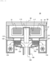
- FIG. 2 is a partial cross-sectional view illustrating an example of a shape of a duct that guides cooling air in the reagent storage.
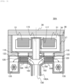
- FIG. 3 is a partial cross-sectional view illustrating another example of the shape of the duct.
- the reagent storage 30 illustrated in FIG. 2 moves a predetermined reagent container 31 to a reagent dispensing position by rotating a rotation shaft 115 by a drive motor 117.
- the reagent storage 30 in order to ensure properties of a reagent stored therein, it is necessary to control the reagent container 31 to a fixed temperature, and thus the reagent storage 30 has a heat insulating function.
- This heat insulating function is ensured by a lid 36 and the housing 38 being implemented by heat insulating members, or by the heat insulating members being provided inside the lid 36 and the housing 38.
Landscapes
- Physics & Mathematics (AREA)
- Health & Medical Sciences (AREA)
- Life Sciences & Earth Sciences (AREA)
- Chemical & Material Sciences (AREA)
- Analytical Chemistry (AREA)
- Biochemistry (AREA)
- General Health & Medical Sciences (AREA)
- General Physics & Mathematics (AREA)
- Immunology (AREA)
- Pathology (AREA)
- Automatic Analysis And Handling Materials Therefor (AREA)
Abstract
In an automatic analyzer 1, a duct 140 provided in the automatic analyzer 1 includes a guide portion that guides air, which flows into a heat sink 120 at a predetermined angle due to a change in the flow direction between an intake port 130 and the heat sink 120, such that the air flows to a side of the heat sink 120 closest to a Peltier element 110. Accordingly, an automatic analyzer including a reagent storage capable of improving the cooling efficiency as compared with the related art is provided.
Description
- The present invention relates to an automatic analyzer.
-
PTL 1 discloses a technique of circulating air in a reagent storage using a fan. - PTL 1:
JP2021-128049A - In
PTL 1, a limitation on volume that can be used for a configuration required for cooling the reagent storage in a small-sized automatic analyzer having a small housing is not considered. - The present invention provides an automatic analyzer including a reagent storage capable of improving cooling efficiency as compared with the related art.
- The invention includes a plurality of means for solving the above problems, and an example thereof includes: a reagent storage configured to store a plurality of reagent containers; a cooling portion configured to cool an inside of the reagent storage; a heat dissipation portion configured to release heat generated in cooling the cooling portion; an intake port configured to take in air to be supplied to the heat dissipation portion from an outside; an exhaust port configured to discharge the air to the outside after the air being supplied to the heat dissipation portion; and a duct that guides the air from the intake port to the heat dissipation portion and guides the air after heat exchange with the heat dissipation portion to the exhaust port. The duct includes a guide portion that guides the air, which flows into the heat dissipation portion at a predetermined angle due to a change in a flow direction of the air between the intake port and the heat dissipation portion, such that the air flows to a side of the heat dissipation portion closest to the heat cooling portion.
- According to the invention, the cooling efficiency can be improved as compared with the related art. Problems, configurations, and effects other than those described above will be clarified by description of the following embodiments.
-
- [
FIG. 1] FIG. 1 is a diagram illustrating an outline of an automatic analyzer. - [
FIG. 2] FIG. 2 is a partial cross-sectional view illustrating an example of a shape of a duct. - [
FIG. 3] FIG. 3 is a partial cross-sectional view illustrating another example of the shape of the duct. - Hereinafter, an embodiment of an automatic analyzer will be described with reference to
FIGS. 1 to 3 . In the drawings used in the present specification, the same or corresponding components are denoted by the same or similar reference signs, and a repeated description of these components may be omitted. - First, an overall configuration of the automatic analyzer will be described with reference to
FIG. 1. FIG. 1 is a diagram illustrating an outline of the configuration of the automatic analyzer. - An
automatic analyzer 1 includes acontrol unit 10 and ananalytical operation unit 20. Theautomatic analyzer 1 has a function of storing a plurality ofreagent containers 31 along an inner side of an outer peripheral wall of acylindrical reagent storage 30 rotatably supported around a vertical axis, aspirating a predetermined amount of a predetermined reagent from thecorresponding reagent container 31 by a dispensing pipette, and supplying the predetermined reagent to a biological specimen such as blood or urine dispensed into areaction container 51 to perform analysis. - First, a transport path of a specimen to be analyzed will be described.
- The specimen to be analyzed is moved in the
automatic analyzer 1 by a specimen transport mechanism (omitted for convenience of illustration) such as a belt conveyor or a rack handler in a state of being contained in aspecimen container 40, and is transported to aspecimen dispensing mechanism 41 to be dispensed that includes a dispensing pipette for dispensing the specimen. - A plurality of
reaction containers 51 are supplied into theautomatic analyzer 1 in a state of being placed in astorage portion 50 that stores unused reaction containers. - After the
reaction containers 51 are gripped one by one by afirst transport mechanism 52 that transports the reaction containers from thestorage portion 50, thereaction containers 51 are lifted and moved to a buffer 42 (a specimen discharge position of the specimen dispensing mechanism 41), and are also moved to agripping position 43 that is a position for gripping thereaction containers 51 on thebuffer 42. In order to enable such movement, thefirst transport mechanism 52 is configured to move in an X-axis direction (a left-right direction inFIG. 1 ), a Y-axis direction (a front-rear direction inFIG. 1 ), and a Z-axis direction (an up-down direction inFIG. 1 ). - A disk-
shaped incubator 25 rotatably supported around a vertical central shaft includes a plurality ofplacement parts 26 for locking the plurality ofreaction containers 51 on the circumference in the vicinity of an outer periphery, and eachreaction container 51 can be moved to a predetermined position by rotating theincubator 25. - Next, the
specimen dispensing mechanism 41 moves to a region above thespecimen container 40, aspirates the specimen, moves to a region above thereaction container 51 on thebuffer 42, and discharges the specimen into thereaction container 51. Thereafter, thespecimen dispensing mechanism 41 cleans a nozzle of the dispensing pipette by a cleaning mechanism (not illustrated). When a replaceable tip is used instead of the nozzle, the tip may be replaced by a replacement mechanism (not illustrated). - Next, a transport path of a reagent to be added to the specimen in the
reaction container 51 will be described. - A
second transport mechanism 60 is configured to move circularly in a range covering thebuffer 42, thegripping position 43, areagent discharging position 33 of areagent dispensing mechanism 32, theplacement part 26 on theincubator 25, and a B/F separation unit 104 of ananalysis unit 100, as a movement range thereof. - The
reagent storage 30 having a cylindrical shape and a cavity inside, which is rotatably supported around a vertical central shaft, forms areagent holding portion 34 in which a plurality ofreagent containers 31 are held radially along ahousing 38 of the inner cavity. Somereagent containers 31 also contain a reagent containing a large number of magnetic particles for agitation. Details of the structure will be described below. - The
reagent dispensing mechanism 32 is configured to aspirate the reagent in thereagent container 31 and move to a predetermined position. First, thereagent dispensing mechanism 32 moves to a region above thereagent container 31 on thereagent storage 30 to aspirate a predetermined amount of reagent, and then moves to a region above thereaction container 51 disposed at thereagent discharging position 33 set around theincubator 25 to discharge the reagent into thereaction container 51. - A first agitation mechanism (not illustrated) capable of agitating the reagent is provided above the
reagent storage 30. The first agitation mechanism is provided with an agitation arm (also referred to as a stirrer) capable of rotating around a vertical axis and agitating magnetic particles. The agitation arm moves to a region above thereagent container 31 containing the reagent to be agitated containing the magnetic particles, lowers, for example, a paddle-like or spiral agitation blade provided at a lower end of the agitation arm into the reagent, and rotates the agitation blade to agitate a magnetic particle solution. In order to prevent the magnetic particles in the solution from naturally precipitating, the agitation arm agitates the magnetic particles immediately before the reagent is dispensed. After the agitation, the agitation arm lifts to above thereagent container 31, moves to a region above the cleaning mechanism containing a cleaning liquid, lowers into the cleaning liquid, and then rotates the agitation blade to remove the magnetic particles adhering to the agitation blade. - After a predetermined reaction time elapses since the specimen and the predetermined reagent are dispensed, a reaction liquid is formed. The
reaction container 51 containing the reaction liquid is moved to the B/F separation unit 104 of theanalysis unit 100 by thesecond transport mechanism 60. - The B/
F separation unit 104 is a mechanism that separates the reaction liquid containing no magnetic particles and the magnetic particles by magnetically attracting the magnetic particles to an inner wall of thereaction container 51 by a magnet 105, the magnetic particles containing a substance that is immunologically bound to a measurement object present in the reaction liquid in thereaction container 51 transported by thesecond transport mechanism 60. - A reaction liquid aspiration nozzle 106 is configured to rotate and move in the up-down direction, moves to above the
reaction container 51 on the B/F separation unit 104 for which a predetermined time elapses, and descends to aspirate the reaction liquid not containing the magnetic particles in thereaction container 51. - A displacement liquid discharge nozzle 108 is configured to rotate and move in the up-down direction, moves to above the
reaction container 51 on the B/F separation unit 104 from which the reaction liquid containing no magnetic particles is aspirated, and descends to discharge a buffer solution into thereaction container 51. - A second agitation mechanism (not illustrated) mixes the magnetic particles and the buffer solution in the reaction container by applying a rotational motion in the
reaction container 51. Thereaction container 51 after mixing is transported to below a measurement channel introduction nozzle by a rotation operation of aturntable 102. - The measurement channel introduction nozzle (not illustrated) is a nozzle that can rotate and move in the up-down direction, and aspirates the reaction liquid in the
reaction container 51 to feed the reaction liquid to a photometry unit. - The photometry unit (not illustrated) detects a concentration of a detection object in the reaction liquid aspirated and fed from the measurement channel introduction nozzle.
- Next, the
reaction container 51 holding the analyzed reaction liquid is moved, by thefirst transport mechanism 52, to a region above a disposal port (not illustrated) for disposing of the reaction container, and is disposed of to the disposal port. - The
automatic analyzer 1 illustrated inFIG. 1 can efficiently analyze a plurality of specimens for a plurality of analysis items by combining or repeating the above operations. - In the
automatic analyzer 1, the mechanisms described above are referred to as theanalytical operation unit 20. - Further, the
automatic analyzer 1 includes, in addition to theanalytical operation unit 20, thecontrol unit 10 that controls an operation of each device in theautomatic analyzer 1. Thecontrol unit 10 includes an operation unit 11, aprocessing unit 12, and astorage unit 13. - The
processing unit 12 includes, for example, a hardware substrate and a computer, and thestorage unit 13 such as a hard disk is built in theprocessing unit 12. - The
storage unit 13 stores, for example, control parameters corresponding to respective units, sample information regarding various samples, and the like. - The
processing unit 12 may be implemented as hardware by a dedicated circuit board, or may be implemented by software executed by a computer. When implementing by hardware, the processing unit can be implemented by integrating a plurality of arithmetic units that execute processing on a wiring board, or in a semiconductor chip or package. When implementing by software, the processing unit can be implemented by mounting a high-speed general-purpose CPU on a computer and executing a program for executing desired arithmetic processing. It is also possible to upgrade an existing device by a recording medium in which the program is recorded. These devices, circuits, and computers are connected by a wired or wireless network, and data is transmitted and received as appropriate. - The operation unit 11 includes a display unit that is a display and an input unit such as a mouse and a keyboard. The display unit displays various types of information on the
automatic analyzer 1 stored in thestorage unit 13. - The above is the configuration of the
automatic analyzer 1. - Although the configuration of the automatic analyzer is described with reference to the case where a photometric unit for analyzing immunoassay as illustrated in
FIG. 1 is mounted, the configuration of the automatic analyzer to which the invention is applied is not limited thereto. For example, the invention can also be applied to an automatic analyzer that includes, in addition or instead, a detection unit for biochemical analysis, a detection unit for biochemical analysis and a detection unit for immunoassay, or a detection unit for other analysis items. - Further, the automatic analyzer is not limited to the form of a single analysis module configuration as illustrated in
FIG. 1 , and may be implemented such that two or more analysis modules capable of measuring various same or different analysis items or preprocessing modules for performing preprocessing are connected by a transport device. - Here, it is necessary to cool an inside of the reagent storage used in the automatic analyzer in order to restrict deterioration of the reagent. Therefore, a cooling portion including, for example, a Peltier element and a heat dissipation portion including, for example, a heat sink connected to the cooling portion are provided.
- In the reagent storage, due to the restriction posed by the arrangement of its rotation shaft, it is necessary to take in air from below and direct the air straight sideways, and then to apply cooling air to the heat dissipation portion. However, when a duct is structured in a shape in which the cooling air is simply guided to the heat dissipation portion, the flow may be disturbed at a portion where a flow direction of the cooling air changes in angle, a difference may occur in supply amount of the cooling air when a cross section of the duct in the flow direction is viewed, and there may be a portion where cooling efficiency decreases. Therefore, it is desirable to stabilize the supply amount of the cooling air.
- In particular, when a heat sink is used in the heat dissipation portion, it is desirable to apply cooling air to a fin base having a high temperature (hereinafter, referred to as a base part), but since it is difficult to supply the cooling air to the base part, it is required to more effectively pass the cooling air. Further, in a small-sized automatic analyzer having a small housing, a volume that can be used for the configuration required for cooling the reagent storage is greatly limited.
- As a structure for solving the above problem, details of the
reagent storage 30 in theautomatic analyzer 1 will be described with reference toFIGS. 2 and3 .FIG. 2 is a partial cross-sectional view illustrating an example of a shape of a duct that guides cooling air in the reagent storage.FIG. 3 is a partial cross-sectional view illustrating another example of the shape of the duct. - The
reagent storage 30 illustrated inFIG. 2 moves apredetermined reagent container 31 to a reagent dispensing position by rotating arotation shaft 115 by adrive motor 117. - In the
reagent storage 30, in order to ensure properties of a reagent stored therein, it is necessary to control thereagent container 31 to a fixed temperature, and thus thereagent storage 30 has a heat insulating function. This heat insulating function is ensured by alid 36 and thehousing 38 being implemented by heat insulating members, or by the heat insulating members being provided inside thelid 36 and thehousing 38. - The inside of the
reagent storage 30 is cooled by cooling acooling jacket 37 by the Peltier element (cooling portion) 110. AlthoughFIG. 2 illustrates a mode in which the cooling efficiency is increased by providing a plurality ofPeltier elements 110, onePeltier element 110 may be provided. The cooling portion is not limited to thePeltier element 110, and may be water cooling or the like. - Here, at the
Peltier element 110, since a heat transfer surface opposite to a heat transfer surface in contact with the coolingjacket 37 generates heat, the heat sink (heat dissipation portion) 120 is brought into contact with the heat transfer surface to release the heat generated in cooling thePeltier element 110. In this way, by dissipating heat by theheat sink 120, it is possible to efficiently dissipate heat without a drive unit. A shape of theheat sink 120 is not particularly limited as long as theheat sink 120 has a shape capable of releasing heat generated in cooling thePeltier element 110. In theheat sink 120, a region on a side close to thePeltier element 110 is abase part 122 that particularly needs to be cooled. - Although the
heat sink 120 is air-cooled, anintake port 130 for taking in cooling air to be supplied to theheat sink 120 from the outside of theautomatic analyzer 1 is provided on a lower side of the housing of theautomatic analyzer 1. - An
exhaust port 135 for discharging the air after being supplied to theheat sink 120 to the outside is provided downstream of eachheat sink 120 on, for example, a side surface on a rear surface side of the housing of theautomatic analyzer 1. - A
duct 140 is provided in order to guide air from theintake port 130 to theheat sink 120 and guide air after heat exchange with theheat sink 120 to theexhaust port 135. - The
duct 140 is branched to supply air to each of twoheat sinks 120. In addition, due to a housing space of theautomatic analyzer 1, the flow direction of air changes between theintake port 130 and theheat sink 120. - In the
duct 140, in particular, in order to efficiently supply the air to thebase part 122, it is necessary to guide the air, which flows into theheat sink 120 at a predetermined angle due to a change in the flow direction, such that the air flows to the side of theheat sink 120 closest to thePeltier element 110. Therefore, theduct 140 is provided with a guide portion. InFIG. 2 , as the guide portion, aplate member 150 perpendicular to a direction in which the air flows in and parallel to a vertical direction is provided in front of an opening portion for receiving the inflow air by a predetermined distance. - With the
plate member 150, turbulence of an air flow, which is caused when the air taken in from theintake port 130 collides with therotation shaft 115 and the flow direction is changed from the vertical direction to a substantially horizontal direction, is reduced so that it is possible to stably supply cooling air for sufficiently cooling thebase part 122 of theheat sink 120. Therefore, it is possible to avoid a decrease in the cooling efficiency of thePeltier element 110. - A
duct 140A in areagent storage 30A illustrated inFIG. 3 is also branched to supply air to each of the twoheat sinks 120, and is also provided with a guide portion since theduct 140A is the same as theduct 140 in thereagent storage 30 illustrated inFIG. 2 in that the flow direction of air changes between theintake port 130 and theheat sink 120. - In
FIG. 3 , as the guide portion, there are provided afirst region second region 164 that is continuous with thefirst region - By the
first region heat sink 120 with thePeltier element 110, and thesecond region 164, turbulence of an air flow, which is caused when the air taken in from theintake port 130 collides with therotation shaft 115 and the flow direction is changed from the vertical direction to the substantially horizontal direction, is reduced so that it is possible to stably supply cooling air for sufficiently cooling thebase part 122 of theheat sink 120. Therefore, it is possible to avoid a decrease in the cooling efficiency of thePeltier element 110. - Next, effects of the embodiment will be described.
- The
duct 140 of theautomatic analyzer 1 described above has a guide portion that guides air, which flows into theheat sink 120 at a predetermined angle due to a change in the flow direction between theintake port 130 and theheat sink 120, such that the air flows to the side of theheat sink 120 closest to thePeltier element 110. - In a case where there is a portion where a flow angle of cooling air changes, it is possible to avoid the occurrence of a portion where the cooling efficiency decreases due to a difference in supply amount of the cooling air when viewing a cross section of the duct in the flow direction, and the cooling air can be applied to the entire heat dissipation portion, particularly the
base part 122, without increasing a pressure loss, so that the cooling efficiency can be improved as compared with that in the related art. - The invention is not limited to the embodiment described above, and various modifications and applications are possible. The embodiments described above are described in detail for easy understanding of the invention, and are not necessarily limited to those having all the configurations described above.
-
- 1:
- automatic analyzer
- 10:
- control unit
- 11:
- operation unit
- 12:
- processing unit
- 13:
- storage unit
- 20:
- analytical operation unit
- 25:
- incubator
- 26:
- placement part
- 30, 30A:
- reagent storage
- 31:
- reagent container
- 32:
- reagent dispensing mechanism
- 33:
- reagent discharging position
- 34:
- reagent holding portion
- 36:
- lid
- 37:
- cooling jacket
- 38:
- housing
- 40:
- specimen container
- 41:
- specimen dispensing mechanism
- 42:
- buffer
- 43:
- gripping position
- 50:
- storage portion
- 51:
- reaction container
- 52:
- first transport mechanism
- 60:
- second transport mechanism
- 100:
- analysis unit
- 102:
- turntable
- 104:
- B/F separation unit
- 105:
- magnet
- 106:
- reaction liquid aspiration nozzle
- 108:
- displacement liquid discharge nozzle
- 110:
- Peltier element (cooling portion)
- 115:
- rotation shaft
- 117:
- drive motor
- 120:
- heat sink (heat dissipation portion)
- 122:
- base part
- 130:
- intake port
- 135:
- exhaust port
- 140, 140A:
- duct
- 150:
- plate member (guide portion)
- 160, 162:
- first region (guide portion)
- 164:
- second region (guide portion)
Claims (5)
- An automatic analyzer comprising:a reagent storage configured to stores a plurality of reagent containers;a cooling portion configured to cool an inside of the reagent storage;a heat dissipation portion configured to release heat generated in cooling the cooling portion;an intake port configured to take in air to be supplied to the heat dissipation portion from an outside;an exhaust port configured to discharge the air to the outside after the air being supplied to the heat dissipation portion; anda duct that guides the air from the intake port to the heat dissipation portion and guides the air after heat exchange with the heat dissipation portion to the exhaust port, whereinthe duct includes a guide portion that guides the air, which flows into the heat dissipation portion at a predetermined angle due to a change in a flow direction of the air between the intake port and the heat dissipation portion, such that the air flows to a side of the heat dissipation portion closest to the heat cooling portion.
- The automatic analyzer according to claim 1, wherein
the heat dissipation portion is a heat sink. - The automatic analyzer according to claim 2, wherein
the guide portion includes a plate member perpendicular to a direction in which the air flows in and parallel to a vertical direction, in front of an opening portion for receiving the inflow air by a predetermined distance. - The automatic analyzer according to claim 2, wherein
the guide portion includes a first region that has a bottom surface inclined upward in an oblique direction from an opening portion for receiving the inflow air, and a second region that is continuous with the first region and has a bottom surface parallel to a horizontal direction. - The automatic analyzer according to claim 1, wherein
a plurality of the cooling portions are provided.
Applications Claiming Priority (2)
| Application Number | Priority Date | Filing Date | Title |
|---|---|---|---|
| JP2022135357 | 2022-08-26 | ||
| PCT/JP2023/027259 WO2024042966A1 (en) | 2022-08-26 | 2023-07-25 | Automatic analysis device |
Publications (2)
| Publication Number | Publication Date |
|---|---|
| EP4579243A1 true EP4579243A1 (en) | 2025-07-02 |
| EP4579243A4 EP4579243A4 (en) | 2026-08-12 |
Family
ID=90013167
Family Applications (1)
| Application Number | Title | Priority Date | Filing Date |
|---|---|---|---|
| EP23857082.4A Pending EP4579243A4 (en) | 2022-08-26 | 2023-07-25 | AUTOMATIC ANALYSIS DEVICE |
Country Status (4)
| Country | Link |
|---|---|
| EP (1) | EP4579243A4 (en) |
| JP (1) | JP7789223B2 (en) |
| CN (1) | CN119654560A (en) |
| WO (1) | WO2024042966A1 (en) |
Family Cites Families (10)
| Publication number | Priority date | Publication date | Assignee | Title |
|---|---|---|---|---|
| JPH05280851A (en) * | 1992-03-30 | 1993-10-29 | Toshiba Corp | Reagent cooler for automatic analyzer |
| JP2003083979A (en) | 2001-09-14 | 2003-03-19 | Furuno Electric Co Ltd | Analysis equipment |
| US7338635B2 (en) * | 2001-09-14 | 2008-03-04 | Furuno Electric Company, Limited | Analyzing apparatus |
| JP2010237021A (en) * | 2009-03-31 | 2010-10-21 | Sysmex Corp | Analyzer |
| JP5432779B2 (en) * | 2010-03-12 | 2014-03-05 | シスメックス株式会社 | Analysis equipment |
| JP5752449B2 (en) * | 2011-03-16 | 2015-07-22 | シスメックス株式会社 | Sample analyzer |
| JP6853090B2 (en) | 2017-03-29 | 2021-03-31 | 株式会社日立ハイテク | Automatic analyzer |
| JP6786563B2 (en) | 2018-09-27 | 2020-11-18 | シスメックス株式会社 | Specimen analyzer, maintenance method |
| EP4119949A4 (en) * | 2020-03-11 | 2024-07-17 | Hitachi High-Tech Corporation | Automated analyzer |
| CN113588975B (en) | 2021-08-27 | 2025-05-09 | 中元汇吉生物技术股份有限公司 | Reagent warehouse, refrigeration system and biochemical analyzer |
-
2023
- 2023-07-25 JP JP2024542679A patent/JP7789223B2/en active Active
- 2023-07-25 WO PCT/JP2023/027259 patent/WO2024042966A1/en not_active Ceased
- 2023-07-25 CN CN202380058206.7A patent/CN119654560A/en active Pending
- 2023-07-25 EP EP23857082.4A patent/EP4579243A4/en active Pending
Also Published As
| Publication number | Publication date |
|---|---|
| WO2024042966A1 (en) | 2024-02-29 |
| JPWO2024042966A1 (en) | 2024-02-29 |
| CN119654560A (en) | 2025-03-18 |
| JP7789223B2 (en) | 2025-12-19 |
| EP4579243A4 (en) | 2026-08-12 |
Similar Documents
| Publication | Publication Date | Title |
|---|---|---|
| JP6768163B2 (en) | Automatic analyzer | |
| US6825041B2 (en) | Method and system for automated immunochemistry analysis | |
| JP7053898B2 (en) | Automated analysis system and sample transport method | |
| AU8520691A (en) | Assay or reaction apparatus | |
| JP2011027663A (en) | Automatic analyzing device | |
| JP7140545B2 (en) | Reagent storage and automatic analyzer | |
| JP7234328B2 (en) | automatic analyzer | |
| JP2010032386A (en) | Reaction table, analyzer, and stirring method | |
| JP2011013148A (en) | Automatic analyzer and magnetic particle moving method | |
| JP7789223B2 (en) | automatic analyzer | |
| EP4270011A1 (en) | Automated analyzer and reagent storage method for automated analyzer | |
| JP7847642B2 (en) | automatic analyzer | |
| JP7739591B2 (en) | automatic analyzer | |
| EP4471428A1 (en) | Automatic analysis device and automatic analysis method | |
| EP4339619A1 (en) | Automatic analysis device | |
| JP7504742B2 (en) | Reagent storage and automatic analyzer | |
| CN113711054B (en) | Automatic analysis device | |
| CN117813512A (en) | Conveying device, specimen analysis system equipped with conveying device, and specimen preprocessing device equipped with conveying device | |
| WO2024062751A1 (en) | Automated analysis device | |
| EP3971581A1 (en) | Automated analyzer | |
| JP7622160B2 (en) | Reagent storage and automatic analyzer | |
| JP2025125903A (en) | Reagent container and automatic analysis device | |
| JP2025144280A (en) | automatic analyzer | |
| JP2002168866A (en) | Enzyme immunoassay | |
| JP2026029908A (en) | Automatic analyzer and dispensing device |
Legal Events
| Date | Code | Title | Description |
|---|---|---|---|
| STAA | Information on the status of an ep patent application or granted ep patent |
Free format text: STATUS: THE INTERNATIONAL PUBLICATION HAS BEEN MADE |
|
| PUAI | Public reference made under article 153(3) epc to a published international application that has entered the european phase |
Free format text: ORIGINAL CODE: 0009012 |
|
| STAA | Information on the status of an ep patent application or granted ep patent |
Free format text: STATUS: REQUEST FOR EXAMINATION WAS MADE |
|
| 17P | Request for examination filed |
Effective date: 20250128 |
|
| AK | Designated contracting states |
Kind code of ref document: A1 Designated state(s): AL AT BE BG CH CY CZ DE DK EE ES FI FR GB GR HR HU IE IS IT LI LT LU LV MC ME MK MT NL NO PL PT RO RS SE SI SK SM TR |
|
| DAV | Request for validation of the european patent (deleted) | ||
| DAX | Request for extension of the european patent (deleted) | ||
| A4 | Supplementary search report drawn up and despatched |
Effective date: 20260708 |